

Firetide FWB-205 User Manual

User Guide
Firetide
FWB-205
Wireless Bridge
2011-09-25 3.1
The contents of this User Guide are subject to change without notice.
Please refer to the Firetide partners web site, partners.retide.com, for current versions.

Caution! Risk of electric shock! Do not open the cover.
Every year, people are killed by touching overhead power lines.
Don’t be one of them. Do not install where possible contact
with power lines can be made. Make sure there is NO possibility
that equipment or personnel can come in contact directly or
indirectly with power lines.
The horizontal distance from a tower, pole or antenna to the
nearest power line should be at least twice the total length
of the pole/antenna combination. This will ensure that the
pole will not contact power if it falls either during or after
installation.
Look over the entire site before beginning any installation and
anticipate possible hazards. Never assume anything without
checking it out for yourself! Don’t take shortcuts!
TO AVOID FALLING, USE SAFE PROCEDURES WHEN WORKING AT
HEIGHTS ABOVE GROUND
• Select equipment locations that will allow safe and simple
installation.
• Don’t work alone. A co-worker can save your life.
• Don’t attempt repair work when you are tired. Not only will
you be more careless, but your primary safety tool -
your brain - will not be operating at full capacity.
• Use approved non-conducting ladders, shoes, and other
safety equipment. Make sure all equipment is in good repair.
• If a tower or pole begins falling, don’t attempt to catch it.
Stand back and let it fall.
• If anything does come in contact with a power line, DON’T
TOUCH IT OR ATTEMPT TO MOVE IT. Instead, save your life by
calling the power company.
• Don’t attempt to erect antennas or towers on windy days.
MAKE SURE ALL TOWERS AND POLES ARE SECURELY GROUNDED,
AND ELECTRICAL CABLES CONNECTED TO ANTENNAS HAVE LIGHTNING ARRESTORS. This will help prevent re damage or human
injury in case of lightning, static build-up, or short circuit within equipment connected to the antenna. Be sure that any other
equipment connected to Firetide products also have protection.
• The base of the antenna pole or tower must be connected
directly to the building protective ground or to one or more
approved grounding rods, using 10 AWG ground wire and
corrosion-resistant connectors.
• Refer to the National Electrical Code for grounding details.
IF AN ACCIDENT SHOULD OCCUR WITH THE POWER LINES DON’T
TOUCH THAT PERSON, OR YOU MAY BE ELECTROCUTED.
• Use a non-conductive dry board, stick, or rope to push or
drag them so they no longer are in contact with electrical
power.
• Once they are no longer contacting electrical power, administer CPR if you are certied.
• Immediately have someone call for medical help.
Limited End User Product Warranty
Pursuant to all provisions described herein, Firetide hardware products and
Firetide antennas are warranted for one (1) year from the date of purchase
against defects in the build materials and workmanship. Firetide does not warrant that the Products will meet any requirements or specications of any End
User Customer. This warranty applies to the entire Firetide product, including
the AC power adapter.
Pursuant to all provisions described herein, Firetide software products are warranted for ninety (90) days from the date of purchase against defects in the
build materials and workmanship. Firetide also warrants that the Software will
materially conform to the documentation supplied by Firetide with the Software.
In the event that the Software fails to materially conform to the documentation
and an authorized Firetide reseller is notied in writing of such failure within
the warranty period, Firetide or its reseller shall use commercially reasonable efforts to promptly correct the nonconformity. Firetide does not warrant that the
use of the Software will be uninterrupted or error free.
The above warranties are void if the alleged defect cannot be veried by Firetide
or if, as determined by Firetide, the product failure was due to tampering, abuse,
misuse, accident, shipping, handling, or storage; or if the product has been
installed, used, or maintained in a manner not described in the product user
manual; or if the product has been altered in any way; or if product serialization
has been altered. Any attempt to disassemble or repair the product by anyone
other than Firetide immediately voids this warranty.
This warranty applies only to the original End User purchaser of the product and
may not be transferred to any other individual or entity.
The foregoing are the exclusive warranties applicable to the product including the software, and the exclusive remedy for defects in the product.
Firetide disclaims all other warranties, whether express, implied, statutory
or otherwise, including but not limited to implied warranties of merchantability, non-infringement or tness for a particular purpose. Some laws do
not allow the exclusion of implied warranties so to that extent this limitation may not apply to you.
In no event will Firetide be liable for any special, incidental, consequential, punitive or indirect damages whatsoever (including, without limitation, damages
for loss of prots, business interruption, loss of information, or other pecuniary
loss) arising out of the use or inability to use the product or the performance,
interruption or failure of the product, irrespective of the cause of action, even if
Firetide has been advised of the possibility of such damages. Firetide’s cumulative liability for all claims arising out of or in connection with this warranty
will not exceed the amount paid by the original End User purchaser to purchase
the product. The amounts payable for the product are based in part on these
limitations and these limitations shall apply notwithstanding the failure of essential purpose of any remedy. Some jurisdictions do not allow the exclusion or
limitation of incidental or consequential damages, so to that extent the above
limitations or exclusions may not apply to you.
By using the product the original End User purchaser agrees to and is bound by
these terms and conditions.
In the event that a product fails to meet this warranty and Firetide’s authorized
reseller is notied in writing of such failure within the warranty period, Firetide
shall, at its own discretion, either repair the product or replace it with the same
or a functionally-equivalent product free of charge. Replacement products may
contain refurbished materials in whole or in part. Firetide will honor this warranty provided the product is returned through an authorized Firetide reseller or
dealer with shipping charges prepaid, along with a proof of purchase describing
the original purchase date and product serial numbers if applicable. The authorized reseller must acquire a Return Materials Authorization (RMA) number from
Firetide prior to returning any product. Firetide does not accept shipments of
defective products without shipping charges prepaid.
Please contact your Firetide dealer for instructions on returning defective or
damaged products for repair or replacement. Do not return products to Firetide,
Inc. Please keep all original packaging materials in the event they are needed
to return the product for servicing.
2 Firetide Wireless Bridge Reference Guide Version 3.1

Table of Contents
Chapter 1 Introduction 4
1.1 Planning Your Installation . . . . . . . . . . . . . . . . . . . . . . . . . . . . . . . . . . . . . . . . 4
Chapter 2 Initial Setup for the FWB-205 6
2.1 Initial Setup & Login . . . . . . . . . . . . . . . . . . . . . . . . . . . . . . . . . . . . . . . . . . 6
Chapter 3 Radio and System Settings 9
3.1 Link Conguration . . . . . . . . . . . . . . . . . . . . . . . . . . . . . . . . . . . . . . . . . . . 9
3.2 Node Conguration . . . . . . . . . . . . . . . . . . . . . . . . . . . . . . . . . . . . . . . . . . .10
3.3 Node Management . . . . . . . . . . . . . . . . . . . . . . . . . . . . . . . . . . . . . . . . . . .10
3.4 Status . . . . . . . . . . . . . . . . . . . . . . . . . . . . . . . . . . . . . . . . . . . . . . . . .12
3.5 Link Status . . . . . . . . . . . . . . . . . . . . . . . . . . . . . . . . . . . . . . . . . . . . . . .12
3.6 Node Status . . . . . . . . . . . . . . . . . . . . . . . . . . . . . . . . . . . . . . . . . . . . . .12
3.7 Upgrade . . . . . . . . . . . . . . . . . . . . . . . . . . . . . . . . . . . . . . . . . . . . . . . .13
3.8 Firmware Upgrade . . . . . . . . . . . . . . . . . . . . . . . . . . . . . . . . . . . . . . . . . . . .13
3.9 Logout. . . . . . . . . . . . . . . . . . . . . . . . . . . . . . . . . . . . . . . . . . . . . . . . .13
Chapter 4 Antenna Installation 14
Chapter 5 Technical Information 18
5.1 FWB-205 Specications . . . . . . . . . . . . . . . . . . . . . . . . . . . . . . . . . . . . . . . . .18
5.2 Reset Procedure . . . . . . . . . . . . . . . . . . . . . . . . . . . . . . . . . . . . . . . . . . . .18
5.3 Regulatory Notices . . . . . . . . . . . . . . . . . . . . . . . . . . . . . . . . . . . . . . . . . . .19
July 2011 Firetide. Reliable Connectivity Anywhere. 3

Chapter 1 Introduction
The FWB-205 provides a point-to-point Ethernet connection between two locations. The devices function
as a low-level Ethernet bridge. Ethernet frames sent to a unit at one end are automatically forwarded to
the other end, and vice-versa. The system is two-way, half-duplex. Sustained link speeds over 100 Mbps
are achievable, and the system will allocate this bandwidth in the two directions dynamcially to meet
trafc needs.
FWB-205 conguration is easy; it can be performed with a browser. Under normal circumstances, the two
units exchange conguration information automatically.
The FWB-205 Kit is shown in Figure 1. Each kit includes two radio modules, two 19-dBi MIMO antennas,
RF cables, two Ethernet PoE injector/powersupplies, two short Ethernet cables, and mounting hardware.
NOTE: The FWB-205 and its two 19 dBi panel antennas are intended for xed (non-mobile), point-to-point
applications only. Any other use is prohibited.
Figure 1. FWB-205 Kit Contents
1.1 Planning Your Installation
You must set the units up on the bench and perform several initial conguration steps prior to installing
the units in the eld. Basic conguration parameters include:
• IP addresses
• Country code
• Radio channels
These must be set prior to eld deployment. The conguration parameters can be modied later, if desired.
Many system designers choose to set all conguration parameters on the bench, prior to eld deployment.
Refer to “Chapter 2 Initial Setup for the FWB-205” on page 6 for basic setup information. Refer to
“Chapter 3 Radio and System Settings” on page 9 for complete software conguration information.
Note that is is not necessary to connect the antennas when performing basic bench conguration. The
units will establish a radio connection without antennas when in close proximity.
4 Firetide Wireless Bridge Reference Guide Version 3.1

1.1.1 Field Installation
After basic software conguration is complete, the units can be deployed in the eld. Installation requires
these tools:
- 1/2-inch open-end wrench
- 7/16-in open-end wrench
- 3/8-inch open-end wrench
- Phillips screwdriver
- Channel-lock or slip-joint pliers
- RJ-45 crimping tool and male plug
- Waterproong tape or mastic for RF connections.
The assembly must be grounded. If the mast is not already properly grounded, you will need appropriate
grounding hardware. Consult local codes.
Refer to “Chapter 4 Antenna Installation” on page 14 for complete installation instructions.
July 2011 Firetide. Reliable Connectivity Anywhere. 5
Chapter 2 Initial Setup for the FWB-205
2.1 Initial Setup & Login
The FWB-205 nodes are sold in pairs. and each pair has been programmed at the factory to work with
each other. Installation of the nodes should only be done by qualied and experienced personnel. Outdoor
installation involves many safety hazards, including electrocution, lightning strikes, and falls. Please be
careful.
In all cases, test and congure the nodes before mounting it on the pole or mast. Set the two nodes up
on the bench and apply power. Wait about 1-2 minutes for the nodes to boot up and establish a radio
connection. The LEDs should look like Figure 2, with both LEDs a steady green color. If the nodes are not
able to establish a connection, the ‘5G’ LED will blink. Proceed anyway.
Figure 2. LED Pattern for Normal Operation
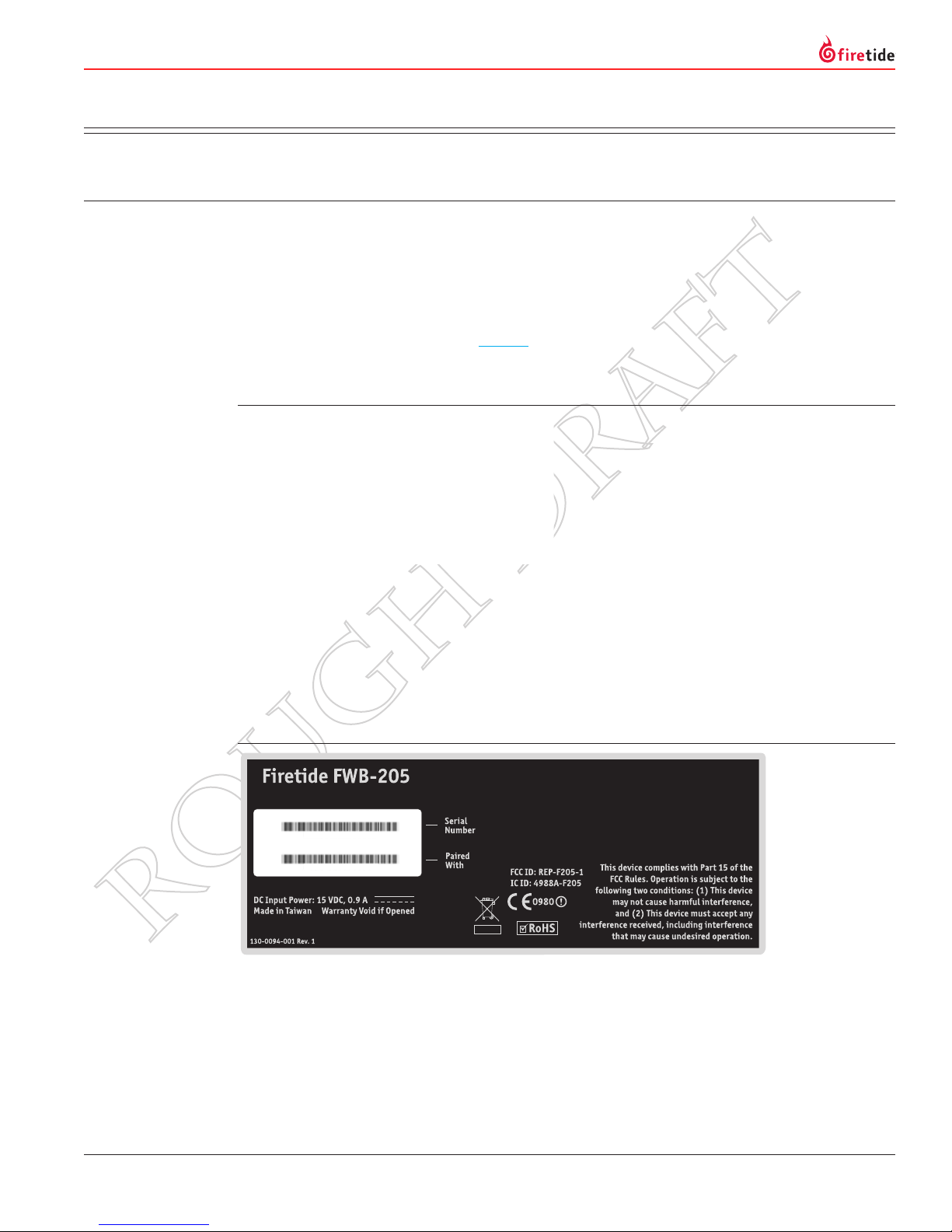
Each unit has a label, as shown, which identies the unit and its partner. (The label is on the bottom of
the unit. You will need to remove the mounting plate to see the label. Use a Philips screwdriver.) FWB
nodes are paired, or “married”, at the factory. Within each pair, the unit with the lower serial number is
assigned IP address 192.168.224.161, and the unit with the higher serial number is assigned IP address
192.168.224.162. Congure your computer to have an IP address on the subnet 192.168.224.0/24. Using
a CAT-5 cable, onnect your computer to the power insertion unit which feeds the lower-numbered member
of the pair.
Figure 3. FWB-205 Label
192.168.224.161
MO 3 2 4 0 8 0 6 0 0 0 1 6 7
192.168.224.162
MO 3 2 4 0 8 0 6 0 0 0 3 9 1
Using an RJ-45 CAT5 cable (not supplied), connect your computer to the unit labeled with the
192.168.224.161 IP address. Point the browser at https://192.168.224.161. Note: use a secure web connection (https) not a conventional connection (http). A website security certicate warning may occur;
ignore it for now. If possible, do NOT add the certicate to your browser’s list of trusted certicates; this
will prevent you from logging into the second node in the pair, should that be necessary.
Note to Firefox users: Firefox will require you to add the certicate in order to proceeds. If you need to
connect to the other node, you must delete the certicate and re-start Firefox.
You will be asked for a login and password; the defaults are admin and retide. You should change these
when you congure the FWB units.
6 Firetide Wireless Bridge Reference Guide Version 3.1

Operating Country
Some Firetide FWB-205 nodes require that you enter the country of operation to ensure compliance with
the channel limitations, indoor/outdoor restrictions, and license requirements of your region. Selecting a
country other than where you are using the device may result in illegal operation and may cause harmful
interference to other systems. The node will reboot after you click Apply to set the country code.
Link Radio Settings
The Link Status eld, under the Link Conguration tab, shows whether or not the two nodes connected.
July 2011 Firetide. Reliable Connectivity Anywhere. 7
 Loading...