

Firetide FWB-100 User Manual
User Guide
Firetide
FWB-100
Wireless Bridge
2010-08-27 Preliminary Version 1.1
The contents of this User Guide are subject to change without notice.
Please refer to the Firetide partners web site, partners.retide.com, for current versions.

Chapter 1. Setting Up Your Equipment
Introduction
Unpacking and Setup
Note that an Ethernet cable is NOT included. You should obtain a weatherproof 4-pair cat-5 cable
Figure 1. FWB-100 Package Contents; Power Injector & Connectors
The Firetide FWB-100 wireless bridge provides wireless point-to-point connectivity for Ethernet
trafc, indoors or out. The FWB-100 is sold in pairs, which have been programmed at the factory to
work with each other. Installation of the devices should only be done by qualied and experienced
personnel. Outdoor installation involves many safety hazards, including electrocution, lightning
strikes, and falls. Please be careful.
A basic FWB-100 is shown in Figure 1. In addition, the FWB is offered as the FWB-102, a pair of
units designed to use the integrated 2.4 GHz antenna built into the bridge. The FWB-105 is a pair
of units including two external antennas designed for 5 GHz. (Note: If you are using a 5 GHz antenna, you must set “Select Active Antenna” to “Antenna 2 (external)”.)
long enough to reach from the unit to the location where you will connect with other equipment.
The cable must be a 4-pair cable; smaller cables will not seal in the waterproof connector. The
cable can be pre-terminated; the waterproof connector will pass an RJ-45 plug.
Assembling the Ethernet Cable
Now you can connect the Ethernet cable to the power feed unit, via the OUT port on the power
2 Firetide FWB-100 Wireless Bridge User Guide August 2010
Test the unit before mounting it on the pole or mast. Begin by making the cable.
1. Remove the weatherproof Ethernet connector cover - the black plug - from the unit.
2. Dismantle it. You will have a housing, a housing insert, a cap, and a gasket.
3. Place the cap over one end of your Ethernet cable.
4. Place the housing insert over the cable.
5. Thread the cable through the housing.
6. Plug the cable into the RJ-45 port visible inside the unit.
7. Thread the housing back into the unit. Make sure the gasket is still in place.
8. Tighten the cap so that it compresses the housing insert to the housing.
feed unit. The CONNECT light should turn green. If the FAULT light comes on, contact Firetide. The
Firetide device needs about two minutes to boot itself. When it completes this process, the Status
will turn green.
Using the Mounting Bracket
The bracket allows easy tilting and aiming of the device. It also allows the unit to be mounted with
its internal antenna oriented for either vertical or horizontal polarization and allows mounting on
either a horizontal or vertical pole. Note that the internal antenna polarization is vertical when the
connectors are pointed down. A 2.4 GHz antenna is built in to the unit. There is also an external
antenna connector. Keep the plastic cover on this connected to prevent water from getting into
the unit.
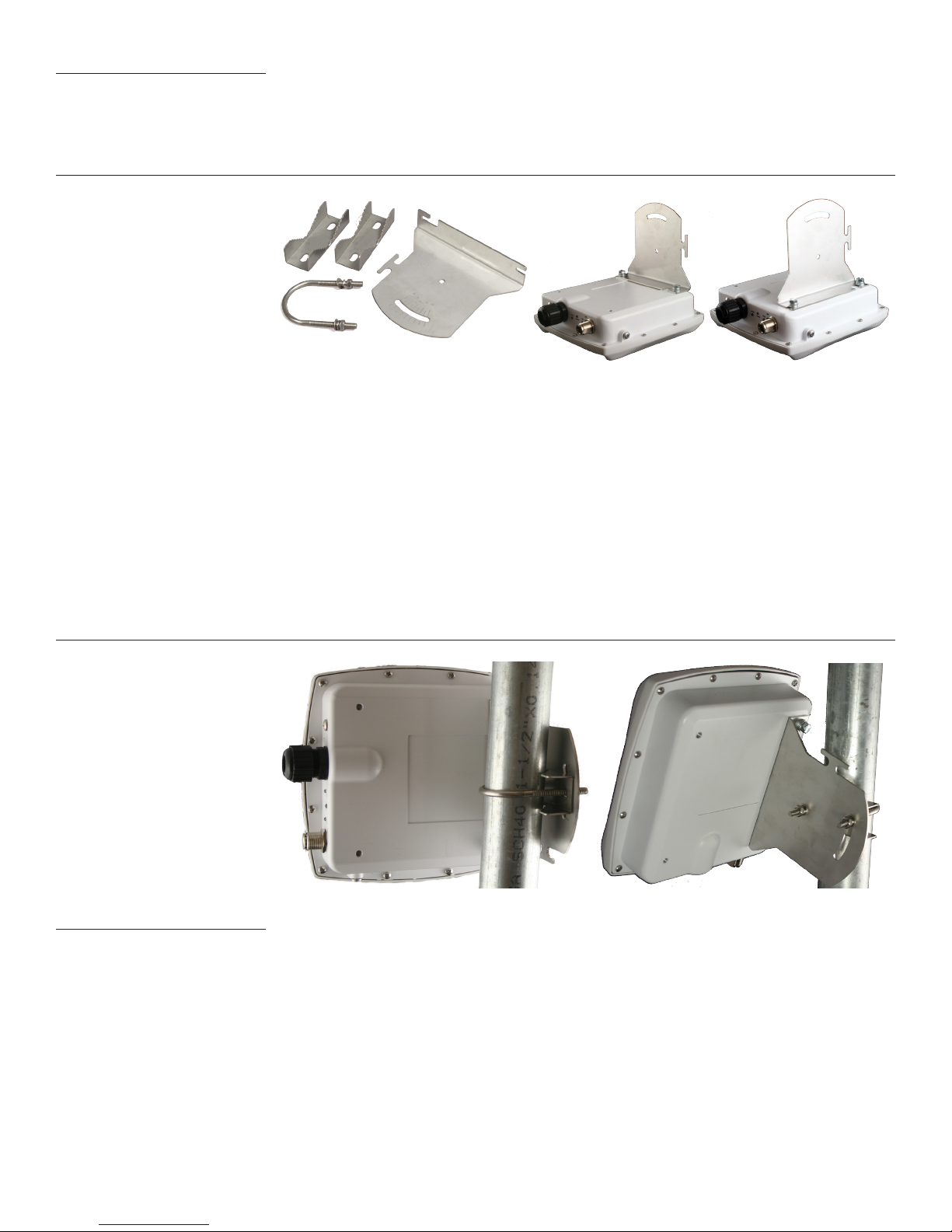
Figure 2. FWB-100 Mounting Bracket
In order to avoid climbing up and down the pole twice, power up the unit before proceeding with
the installation. The only connection you need is the Ethernet; it provides power as well.
Attach the bracket to the back of the unit, using the two slotted holes shown on the right side of
the bracket, as shown in Figure 2. Select two holes on the unit according to the desired orientation
of the pole and the antenna.
The bracket is attached to the pole using the U-bolt and one or two of the supplied jaw-clamps
(Figure 3). One jaw-clamp is used between the bracket and the pole; the second clamp may be used
on smaller-diameter poles by placing it over the U-bolt before putting the U-bolt around the pole.
After placing the U-bolt around the pole, place the bracket over the legs of the U-bolt such that
one leg passes through the round hole and the other leg passes through the curved slot. Snug the
bracket slightly with the supplied nuts and lockwashers, but do not tighten until you have aligned
the unit. The result should resemble Figure 3.
Figure 3. U-bolt Mounting Assembly; Tilting the Unit for Signal Alignment
Aligning the FWB
The Alignment LED provides a visual indication of signal strength. Point the FWB in the direction
of its signal source, then carefully adjust it, both horizontally and vertically, using the Alignment
LED as a guide. The LED will blink more rapidly as the signal strength increases. When you receive
the strongest signal, tighten the nuts. Figure 3 shows how the bracket can be used to tilt the unit.
The LED alignment feature is enabled by default. To insure maximum performance, you should dis-
able the feature via the web interface after installation is complete. If you are re-aligning antennas, be sure to re-enable the alignment feature.
Firetide. Reliable Connectivity Anywhere 3 Preliminary Version 1.1
Chapter 2. Conguring the FWB-100
Initial Setup & login
Firetide FWB units are shipped in pairs, and must be congured prior to deployment in the eld.
Set the two units up on the bench and apply power. Wait about 1-2 minutes for the units to boot
up and establish a radio connection.
Each unit has a label, as shown below, which identies the unit and its partner (see highlighted
area). Connect your computer to the power insertion unit which feeds the lower-numbered member
of the pair.
Firetide Wireless Bridge
(FWB)
0980
FCC ID: REP-4200
IC ID: 4988A-4200
This device complies with Part 15 of the FCC
Rules. Operation is subject to the following
twoconditions:
(1) This device may not caus e har mful
interference, and (2)This device must accept
an y inte rfe ren ce rec eiv ed, in clu ding
inte rferenc e t hat may cause un desired
operation.
Input Power: 48 VDC POE, 0.25 A
Made in China
Warranty Void if Opened
Antenna
Polarity
H
V
S/N
Paired
with
MO 3 2 4 0 8 0 6 0 0 0 1 6 7
MO 3 2 4 0 8 0 6 0 0 0 3 9 1
192.168.224.161
192.168.224.162
FWB nodes are paired, or “married”, at the factory. Within each pair, the unit with the lower serial
number is assigned IP address 192.168.224.161, and the unit with the higher serial number is assigned IP address 192.168.224.162. You can change these addresses if desired.
Congure the computer to have an IP address on the subnet 192.168.224.0/24. When you power
up the two units on the bench, they will usually connect. If they do, connect to the unit labeled
with the 192.168.224.161 IP address. Point the browser at https://192.168.224.161. You will be
asked for a login and password; the defaults are admin and retide. You should change these when
you congure the FWB units. Proceed to set the country code.
If the two nodes did not connect with each other, you must point your browser at the second node,
at https://192.168.224.162. Log in as above, and set its country code.
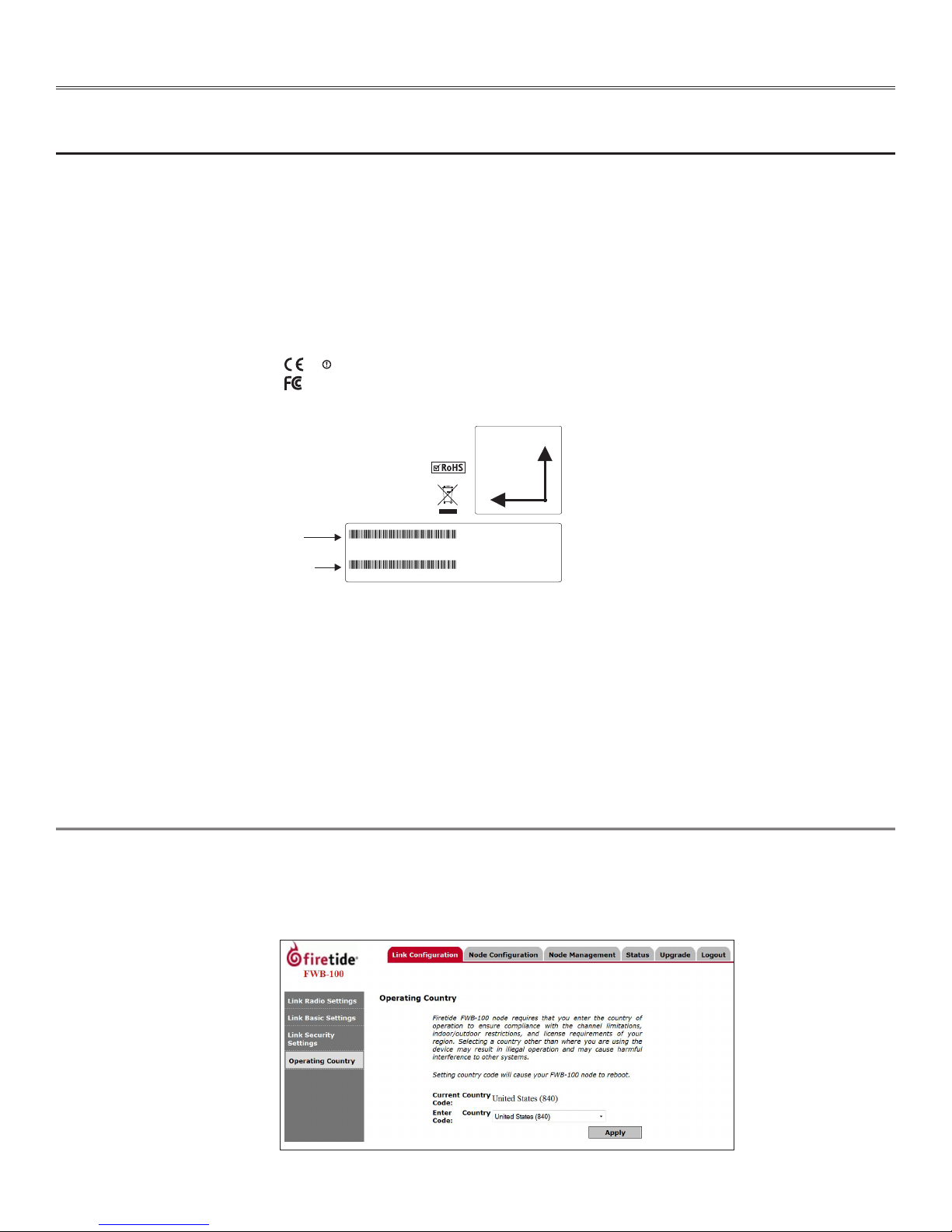
Operating Country
Firetide FWB-100 nodes require that you enter the country of operation to ensure compliance
with the channel limitations, indoor/outdoor restrictions, and license requirements of your region.
Selecting a country other than where you are using the device may result in illegal operation and
may cause harmful interference to other systems. The node will reboot after clicking Apply to set
the country code.
4 Firetide FWB-100 Wireless Bridge User Guide August 2010
 Loading...