

Firetide 3200-1 manual update
Hardware Installation
Guide
HotPort 3203 Outdoor Wireless
Mesh Node

Regulatory Approvals
FCC Statement
This equipment has been tested and found to comply with the limits for a Class B digital
device, pursuant to Part 15 of the FCC Rules. These limits are designed to provide reasonable
protection against harmful interference in a residential installation.
This equipment generates, uses and can radiate radio frequency energy and, if not installed and
used in accordance with the instructions, may cause harmful interference to radio communications. However, there is no guarantee that interference will not occur in a particular installation.
If this equipment does cause harmful interference to radio or television reception, which can be
determined by turning the equipment off and on, the user is encouraged to try to correct the
interference by one of the following measures:
Reorient or relocate the receiving antenna.
Increase the separation between the equipment and receiver.
Connect the equipment into an outlet on a circuit different from that to which the receiver
is connected.
Consult the dealer or an experienced radio/TV technician for help.
To assure continued compliance, any changes or modifications not expressly approved by the
party responsible for compliance could void the user's authority to operate this equipment.
(Example - use only shielded interface cables when connecting to computer or peripheral
devices).
FCC Radiation Exposure Statement
This equipment complies with FCC RF radiation exposure limits set forth for an uncontrolled
environment. This equipment should be installed and operated with a minimum distance of 20
centimeters between the radiator and your body.
This device complies with Part 15 of the FCC Rules. Operation is subject to the following two
conditions:
(1) This device may not cause harmful interference, and
(2) This device must accept any interference received, including interference that may cause
undesired operation.
This transmitter must not be co-located or operating in conjunction with any other antenna or
transmitter.
The antennas used for this transmitter must be installed to provide a separation distance of at
least 20 cm from all persons and must not be co-located or operating in conjunction with any
other antenna or transmitter.
Channel
The Wireless Channel sets the radio frequency used for communication.
•Access Points use a fixed Channel. You can select the Channel used. This allows you to
choose a Channel which provides the least interference and best performance. In the USA
and Canada, 11 channel are available. If using multiple Access Points, it is better if adjacent
Access Points use different Channels to reduce interference.
• In "Infrastructure" mode, Wireless Stations normally scan all Channels, looking for an
Access Point. If more than one Access Point can be used, the one with the strongest
signal is used. (This can only happen within an ESS.)
• If using "Ad-hoc" mode (no Access Point), all Wireless stations should be set to use the
same Channel. However, most Wireless stations will still scan all Channels to see if there
is an existing "Ad-hoc" group they can join.
CAUTION:
1) To comply with FCC RF exposure compliance requirements, a separation
distance of at least 20 cm must be maintained between the antenna of this
device and all persons.
2) This transmitter must not be co-located or operating in conjunction with
any other antenna or transmitter.
3) The device belong to outdoor unit, so it is disabled from 5.15 to 5.25GHz.

HotPort 3203 Outdoor Wireless Mesh Node
Hardware Installation Guide
HotPort 3203 Outdoor Wireless Mesh Node
April 2005
Manual Revision 0.9 - 3.31.05
Copyright Notice
© 2003-2005 Firetide, Inc. All rights reserved.
Trademarks
Firetide, the Firetide logo, Wireless Instant Networks, HotPort are trademarks of Firetide, Inc. All other
trademarks are the property of their respective owners.
ii

Hardware Installation Manual
HotPort Limited End User Product Warranty
Pursuant to all provisions described herein, Firetide products are warranted for one (1) year from
the date of purchase against defects in the build materials and workmanship. Firetide also
warrants that the Software will materially conform to the documentation supplied by Firetide with
the Software. In the event that the Software fails to materially conform to the documentation and
an authorized Firetide reseller is notified in writing of such failure within the warranty period,
Firetide or its reseller shall use commercially reasonable efforts to promptly correct the
nonconformity. Firetide does not warrant that the use of the Software will be uninterrupted or error
free. Firetide does not warrant that the Products will meet any requirements or specifications of
any End User Customer. This warranty applies to the entire Firetide product, including antennas
and the AC power adapter.
The above warranties are void if the alleged defect cannot be verified by Firetide or if, as
determined by Firetide, the product failure was due to tampering, abuse, misuse, accident,
shipping, handling, or storage; or if the product has been installed, used, or maintained in a
manner not described in the product user manual, if the product has been altered In any way, or If
product serialization has been altered. Any attempt to disassemble or repair the product by
anyone other than Firetide immediately voids this warranty.
This warranty applies only to the original End User purchaser of the product and may not be
transferred to any other individual or entity.
THE FOREGOING ARE THE EXCLUSIVE WARRANTIES APPLICABLE TO THE PRODUCT
INCLUDING THE SOFTWARE, AND THE EXCLUSIVE REMEDY FOR DEFECTS IN THE
PRODUCT. FIRETIDE DISCLAIMS ALL OTHER WARRANTIES, WHETHER EXPRESS,
IMPLIED, STATUTORY OR OTHERWISE, INCLUDING BUT NOT LIMITED TO IMPLIED
WARRANTIES OF MERCHANTABILITY, NON-INFRINGEMENT OR FITNESS FOR A
PARTICULAR PURPOSE. SOME LAWS DO NOT ALLOW THE EXCLUSION OF IMPLIED
WARRANTIES SO TO THAT EXTENT THIS LIMITATION MAY NOT APPLY TO YOU.
In no event will Firetide be liable for any special, incidental, consequential, punitive or indirect
damages whatsoever (including, without limitation, damages for loss of profits, business
interruption, loss of information, or other pecuniary loss) arising out of the use or inability to use
the product or the performance, interruption or failure of the product, irrespective of the cause of
action, even if Firetide has been advised of the possibility of such damages. Firetide's cumulative
liability for all claims arising out of or in connection with this warranty will not exceed the amount
paid by the original End User purchaser to purchase the product. The amounts payable for the
product are based in part on these limitations and these limitations shall apply not-withstanding
the failure of essential purpose of any remedy. Some jurisdictions do not allow the exclusion or
limitation of incidental or consequential damages, so to that extent the above limitations or
exclusions may not apply to you.
By using the product the original End User purchaser agrees to and is bound by these terms and
conditions.
In the event that a product fails to meet this warranty and Firetide’s authorized reseller is notified
in writing of such failure within the warranty period, Firetide shall, at its own discretion, either
repair the product or replace it with the same or a functionally-equivalent product free of charge.
Replacement products may contain refurbished materials in whole or in part. Firetide will honor
this warranty provided the product is returned through an authorized Firetide reseller or dealer
with shipping charges prepaid, along with a proof of purchase describing the original purchase
date and product serial numbers if applicable. The authorized reseller must acquire a Return
Materials Authorization (RMA) number from Firetide prior to returning any product. Firetide does
not accept shipments of defective products without shipping charges prepaid.
iii
HotPort 3203 Outdoor Wireless Mesh Node
Safety Instructions
The HotPort 3203 outdoor wireless mesh node must be installed by a qualified
professional such as a licensed electrician. Failure to install this equipment properly may
result in equipment damage and personal injury or death.
Explanation of Graphic Symbols
This symbol is intended to alert the user to the presences of non-insulated dangerous
voltage that may be of sufficient magnitude to constitute a risk of lethal electric shock to persons.
This symbol is intended to alert the user to the presence of important operating,
maintaining and servicing instructions in the literature accompanying the HotPort 3203. Failing to
comply with this instruction may result in electrical shock.
This symbol is intended to alert the user to the presence of important operating,
maintaining and servicing instructions in the literature accompanying the HotPort 3203. Failing to
comply with this instruction may result in a hazard.
Caution! Risk of electric shock!
POWER LINES CAN BE LETHAL
Do not install the HotPort 3203 outdoor mesh node where possible contact with power lines can
be made. Antennas, poles, towers, guy wires, or cables may lean or fall and contact these lines.
People may be injured or killed if they are touching or holding any part of equipment when it
contacts electric lines. Make sure there is NO possibility that equipment or personnel can come in
contact directly or indirectly with power lines.
ASSUME ALL OVERHEAD LINES ARE POWER LINES
The horizontal distance from a tower, pole or antenna to the nearest power line should be at least
twice the total length of the pole/antenna combination. This will ensure that the pole will not
contact power if it falls either during or after installation.
SURVEYING THE SITE
Look over the entire site before beginning any installation and anticipate possible hazards. Never
assume anything without checking it out for yourself! Don't take shortcuts!
iv
Hardware Installation Manual
Caution! Risk of electric shock!
TO AVOID FALLING, USE SAFE PROCEDURES WHEN WORKING AT HEIGHTS ABOVE
GROUND
• Select equipment locations that will allow safe and simple installation.
• Don’t work alone. A friend or co-worker can save your life if an accident happens.
• Don't attempt repair work when you are tired. Not only will you be more careless, but your
primary diagnostic tool - deductive reasoning - will not be operating at full capacity.
• Use approved non-conducting ladders, shoes, and other safety equipment. Make sure all
equipment is in good repair.
• If a tower or pole begins falling, don’t attempt to catch it. Stand back and let it fall.
• If anything such as a wire or pole does come in contact with a power line, DON’T TOUCH IT
OR ATTEMPT TO MOVE IT. Instead, save your life by calling the power company.
• Don’t attempt to erect antennas or towers on windy days.
• MAKE SURE ALL TOWERS AND POLES ARE SECURELY GROUNDED, AND
ELECTRICAL CABLES CONNECTED TO ANTENNAS HAVE LIGHTNING ARRESTORS.
This will help prevent fire damage or human injury in case of lightning, static build-up, or short
circuit within equipment connected to the antenna. The HotPort 3203 has built in lightning
protection. Be sure that any other equipment connected to the HotPort 3203 also has the
same level of protection.
• The base of the antenna pole or tower must be connected directly to the building protective
ground or to one or more approved grounding rods, using 10 AWG ground wire and
corrosion-resistant connectors.
• Refer to the National Electrical Code for grounding details.
IF AN ACCIDENT SHOULD OCCUR WITH THE POWER LINES
• DON’T TOUCH THAT PERSON, OR YOU MAY BE ELECTROCUTED.
• Use a non-conductive dry board, stick, or rope to push or drag them so they no longer are in
contact with electrical power.
• Once they are no longer contacting electrical power, administer CPR if you are certified.
• Immediately have someone call for medical help.
DO NOT OPEN THE COVER
• Dangerous voltages inside.
• No serviceable parts inside.
• Refer to qualified service personnel.
• Unit must be disconnected from power prior to servicing.
• Unit has tamper-evident labeling that indicates when the cover has been removed.
v

HotPort 3203 Outdoor Wireless Mesh Node
Table of Contents
FIRETIDE HOTPORT 3203 OUTDOOR WIRELESS MESH NODE.................................................................... 8
EXAMPLE NETWORKS/APPLICATIONS ..................................................................................................... 9
PLANNING YOUR NETWORK ..................................................................................................................... 9
POWER OPTIONS ...................................................................................................................................... 10
Power Supply ....................................................................................................................................... 10
Power over Ethernet (PoE)................................................................................................................... 10
HOTPORT 3203 INSTALLATION................................................................................................................... 11
UNPACKING ............................................................................................................................................. 11
Mesh Node............................................................................................................................................ 11
Antenna Assembly ............................................................................................................................... 11
Ethernet Transition Cable/RJ-45 Male Connector Kit......................................................................... 11
Power Supply ....................................................................................................................................... 11
Documentation..................................................................................................................................... 11
Compact Disk (CD).............................................................................................................................. 11
REQUIRED TOOLS AND SUPPLIES............................................................................................................. 12
BUILDING A FIRETIDE MESH NETWORK .................................................................................................... 13
PLANNING YOUR NETWORK ................................................................................................................... 13
Understanding HotPort Antenna Patterns ......................................................................................... 13
STAGING CONSIDERATIONS .................................................................................................................... 14
PREPARING THE SITE FOR MOUNTING .................................................................................................... 15
Safety Considerations........................................................................................................................... 15
Weatherproofing................................................................................................................................... 15
Preparing Earth Ground ...................................................................................................................... 15
MOUNTING THE ANTENNA..................................................................................................................... 17
Mounting Guidelines ........................................................................................................................... 17
MOUNTING THE ENCLOSURE .................................................................................................................. 21
Mounting Guidelines ........................................................................................................................... 21
Wall Mounting..................................................................................................................................... 21
Pole Mounting...................................................................................................................................... 22
Installing the Sunshield........................................................................................................................ 26
CONNECTING THE POWER....................................................................................................................... 27
Connecting AC Power.......................................................................................................................... 27
Connecting Power over Ethernet ......................................................................................................... 28
Connecting Solar Power....................................................................................................................... 28
CONNECTING PERIPHERALS .................................................................................................................... 29
Providing Power over Ethernet to Peripherals..................................................................................... 29
STARTING UP AND CONNECTING TO THE MESH .................................................................................... 31
Startup Sequence.................................................................................................................................. 31
Connecting to the Mesh........................................................................................................................ 31
APPENDIX A- CONTACTING FIRETIDE........................................................................................................ 33
vi

Hardware Installation Manual
PPENDIX B - CONNECTORS ....................................................................................................................... 34
A
HOTPORT 3203 ETHERNET TRANSITION CABLE PIN DESCRIPTIONS ..................................................... 34
Circular, Watertight IP67-Rated Connector and Port Pin Descriptions............................................. 34
RJ-45 Connector Pin Descriptions....................................................................................................... 34
POWER TRANSITION CABLE PIN DESCRIPTIONS ..................................................................................... 35
APPENDIX C - SPECIFICATIONS................................................................................................................... 36
vii

Firetide HotPort 3203 Outdoor Wireless Mesh Node
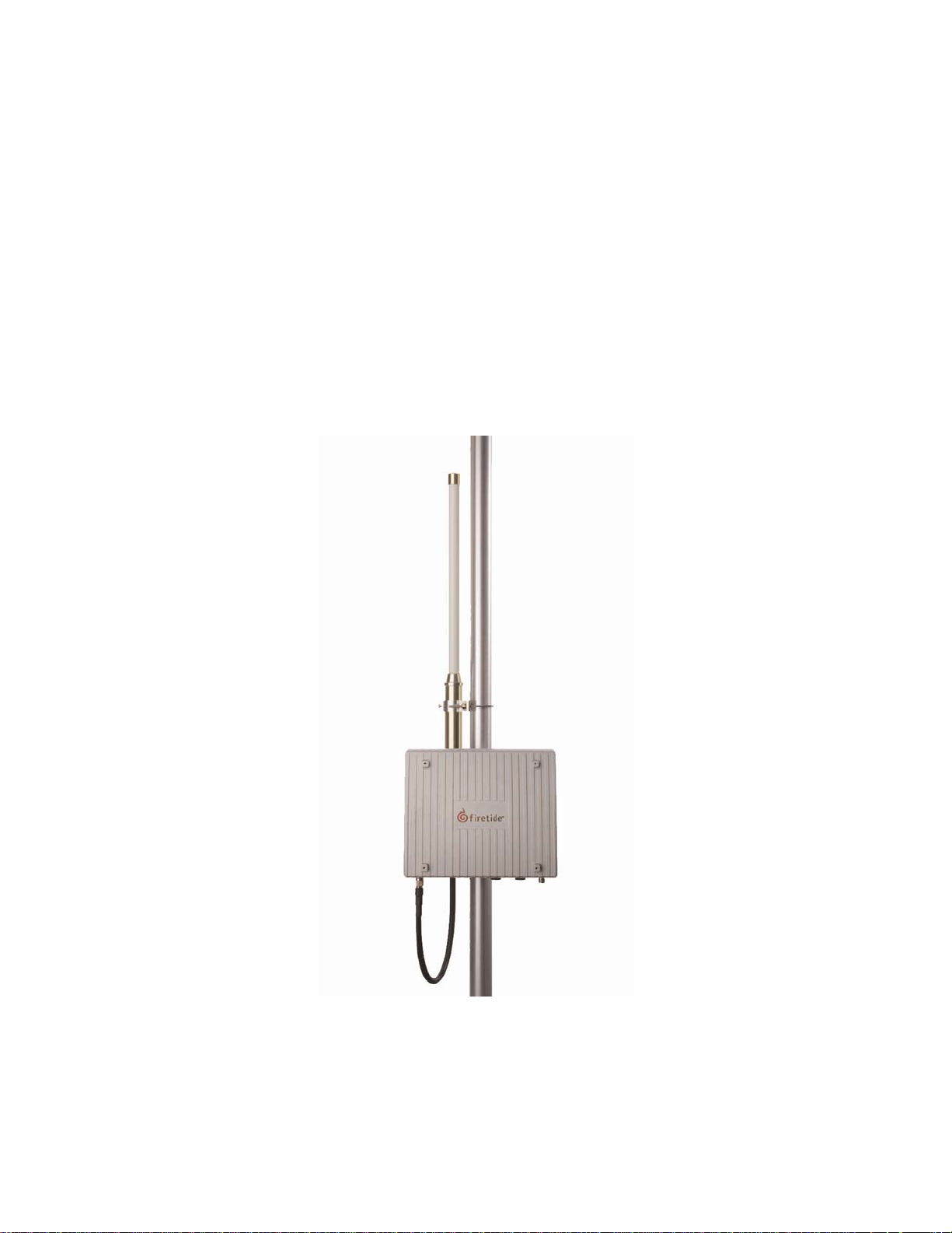
HotPort™ 3200 series outdoor mesh nodes have weatherproof enclosures and connect
wirelessly to indoor and outdoor HotPort nodes to form a high-performance wireless mesh
network. Outdoor nodes feature a built-in dual-port 10/100 Ethernet switch, a dual-spectrum
radio, and omni-directional antennas. They can operate at 2.4 GHz for maximum capacity and
range, or at 5 GHz for maximum capacity and minimal interference from 2.4 GHz devices. Both
Ethernet ports are weatherproof and support 802.3af Power over Ethernet (PoE). A removable
sunshield and a mounting bracket are provided with each unit. Options include integrated backup
battery and solar powered charger.
The HotPort 3203 provides Ethernet connectivity for outdoor devices without the need for a wired
backhaul. This enables fast deployment of outdoor networking equipment, such as weatherized
access points and surveillance cameras, virtually anywhere, without costly cabling.
Firetide™ mesh networks provide a reliable, flexible, and scalable alternative to cabling and
leased lines. Because they form automatically without wires and do not require line-of-sight,
Firetide mesh networks can be installed without modifications to buildings or landscaping.
Outdoor network installation costs are dramatically lower because time-consuming trenching and
cable pulling between buildings is not required. Provisioning is also easy and fast because no
special drivers, setup, and interfaces are required for the equipment you connect to a Firetide
instant mesh network.
While operating at 5 GHz, the HotPort 3203’s radio can cover distances up to 2600 ft (800 m).
This long reach between HotPort mesh nodes enables you to extend your network to areas that
are otherwise too distant, expensive, difficult, or environmentally sensitive to wire with LAN cable.
The two weatherproof 10/100 Ethernet connectors provide for connecting Ethernet devices, such
as access points, surveillance cameras, and sensors. The package includes an indoor-rated
power supply, with a country- or region-specific power cord and a 10 m (33 ft) power transition
cable, which can supply power from an AC power source. The HotPort 3203 mesh node can
supply Power over Ethernet to auxiliary Ethernet devices up to a maximum of 48 VDC. Two omnidirectional antennas attach to the bottom of the HotPort 3203 enclosure via a connector and
cable.
Because all mesh nodes are interconnected, a single gateway can provide Internet access to the
entire mesh network. HotPort 3203 outdoor mesh nodes are fully compatible with HotPort 3103
nodes, enabling the mesh to extend to indoor applications.
8
Firetide HotPort 3203 Node

HotPort 3203 Outdoor Wireless Mesh Node
Example Networks/Applications
Below are some examples of how you can use HotPort wireless mesh networks in your
workplace.
• Provide Ethernet service over a wireless backhaul to buildings where wired solutions via
Category 5 cabling or fiber is impractical or too expensive.
• Connect access points to networks from locations where it is impractical to run cable to
the access points.
• Connect security cameras to monitor remote locations.
Planning Your Network
Before implementing a wireless mesh network, perform the following preliminary steps:
• To ensure a safe installation of the HotPort 3203, follow the appropriate electrical and
building codes (like the National Electrical Code (NEC)), country codes, or local building
codes.
• When identifying a location for mounting the antenna, keep in mind that you should not
mount the antenna within 3 ft (0.9 m) of another antenna. If you do, interference may
occur.
• You can increase the working distance of your wireless mesh by avoiding obstacles
between nodes. For best performance, ensure that there is a clear line of sight between
each HotPort node.
• Look for physical obstructions, such as building or trees, and avoid installing the antenna
where there is obstruction between antennas. Installations in winter months around trees
may not pose a problem, but once the leaves appear they may pose an obstruction.
• Keep in mind that buildings may cause radio signal obstruction, depending on the
material used in construction.
• Avoid areas with heavy vehicle and foot traffic. Do not install near rain gutters and
downspouts or areas subject to flooding.
• Consider ways to protect your HotPort node from theft and vandalism. Try to place
HotPort nodes in areas where access by unauthorized individuals is restricted (such as
on a rooftop, a tall pole, and so on). (After you mount the HotPort, you can secure it by
placing a lock on the mounting bracket.)
• Survey the site for grounding options. It is crucial to have earth ground.
• Make sure that the horizontal distance from a tower, pole, or antenna to the nearest
power line is at least twice the total length of the pole/antenna combination. This will
prevent the tower, pole, or antenna from contacting power if it falls either during or after
installation.
• Make sure that you can install the HotPort node close enough to an AC power outlet so
you can connect the HotPort node’s AC power supply to the outlet. If you plan to power a
HotPort node via an Ethernet connection (using the Power over Ethernet option), make
sure you have an Ethernet cable long enough to connect the HotPort node to the Power
Sourcing Equipment (see the “Connecting the Power” section for information).
• Make sure the location where you install the HotPort node is accessible to the devices
you intend to connect to the HotPort node (access points, cameras, and so on).
• If you plan to provide a battery backup or use solar power, make sure you have a reliable
battery to use for power storage. If using solar power, and the solar unit does not include
a battery, obtain the proper battery for power storage.
9

Hardware Installation Guide
Power Options
There are various options for supplying power to the HotPort 3203.
Power Supply
The power supply can provide power to the HotPort 3203 enclosure from an AC outlet. The
power supply is rated for 90-240 VAC. Optionally, when the HotPort 3203 receives power from
the power supply, you can provide power to two peripheral devices connected to the HotPort
3203’s Ethernet ports.
Power over Ethernet (PoE)
The HotPort 3203 outdoor mesh node has two weatherproof Ethernet ports to provide Ethernet
connectivity to outdoor peripheral Ethernet devices, such as access points or surveillance
cameras. Use of these ports is optional.
Both ports 1 and 2 on a HotPort 3203 can provide Power over Ethernet (PoE) functionality to
Powered Devices (PD) connected to these ports. A Powered Device can receive data and the
power to process the data from the HotPort 3203, which functions as Power Sourcing Equipment
(PSE) in this configuration. To receive power from a HotPort 3203, the device must support the
IEEE 802.3af standard, which defines PoE functionality.
Alternatively, you can connect Power Sourcing Equipment to Ethernet port 1 on a HotPort 3203 to
allow the HotPort to receive power from a PSE device.
10

HotPort 3203 Outdoor Wireless Mesh Node
HotPort 3203 Installation
This hardware installation guide describes how to install the HotPort 3203 safely. The HotPort is
intended to be installed by trained technical professionals. Be sure to read and understand all
installation instructions and safety instructions before proceeding with the installation.
Unpacking
The HotPort 3203 package contains the following items. If you are missing any of these items,
contact your Firetide reseller.
Mesh Node
• HotPort 3203 with NEMA-4X enclosure with weatherproof connector caps
• Lockable bracket for pole and wall mounting
Antenna Assembly
• Two detachable dual-spectrum (2.4 or 5 GHz), 6 dBi, omni-directional antennas
Note: Each HotPort 3203 comes with two dual-spectrum, 6 dBi antennas. Use these antennas to
determine which RF frequency band (2.4 or 5 GHz) to use. After you decide, you can order a single,
spectrum-specific (that is, 2.4 or 5 GHz) high-gain, 8 dBi antenna to use outdoors with your HotPort.
Throughout this manual, references are made to a single, high-gain 8 dBi antenna unl ess the two
dual-spectrum antennas shipped with the unit are involved.
Ethernet Transition Cable/RJ-45 Male Connector Kit
• Weatherized Ethernet transition cable (2 m (6.6 ft)), circular, watertight, IP67-rated
female to RJ-45/RJ-45 male connector kit with Bulgin connector housing
Power Supply
• Country- or region-specific power cord, power transition cable (10 meters (32.8 ft); 30 m
(98.4 ft), and 50 m (164 ft) cable lengths available for order from Firetide) and an indoorrated power supply
Documentation
• 3203 Hardware Installation Guide (this document)
• 3203 User Guide
• End user license agreement (EULA)
• Warranty and registration card
Compact Disk (CD)
• HotView software
• 3203 Hardware Installation Guide (this document in a PDF file)
• 3203 User Guide (PDF file)
• HotView User Guide (PDF file)
• EULA (PDF file)
• Warranty Information (PDF file)
11
 Loading...