


44 Elite Installation Manual
Wood-Burning
Zero-Clearance
Fireplace
© 2010, Travis Industries
4800 Harbour Pointe Blvd. SW
Mukilteo, WA 98275 $10.00 93508093 www.travisproducts.com
Tested and Listed by
OMNI-Test Laboratories, Inc.
Beaverton, Oregon
Report # 028-F-61-4
U.L. 127 & portions of 1482 & 907
2 |
Introduction |
Overview
This manual details the installation requirements for the 44 ELITE wood-burning fireplace. For operating and maintenance instructions, refer to the 44 ELITE Owner's Manual (part # 93508094).
Listing Details
This appliance was listed by OMNI Test Labs to U.L. 127 and portions of U.L. 1482 and 907 – report number 028-F-61-4. The listing label is attached to the base of the fireplace and can be viewed by removing the faceplate (see Figure 1 below).
|
|
|
Fireplace Xtrordinair |
||
|
|
|
LISTED FACTORY BUILT FIREPLACE |
MODEL NO. 44 ELITE |
|
|
|
|
TESTED TO: UL-127 |
REPORT NO. 028-F-61-4 |
|
|
|
||||
|
|
||||
WARNING: • Operate with feed doors closed. Open to feed fire only. |
• For use with solid fuel only. |
||||
U.S. ENVIRONMENTAL PROTECTION AGENCY
Certified to comply with July, 1990 particulate emission standards.
This wood heater contains a catalytic combustor which needs periodic inspection and replacement for proper operation. Consult the owner’s manual for further information. It is against the law to operate this wood heater in a manner inconsistent with operating instructions in the owner’s manual or if the catalytic element is deactivated or removed.
Do not use a fireplace insert or other products not specified for use with this product. This fireplace has not been tested with an unvented gas log set. To reduce risk of fire or injury, do not install an unvented gas log set into fireplace.
DO NOT REMOVE THIS LABEL
SERIAL NO.
|
|
MANUFACTURE DATE: |
|
|
|||||
|
2006 |
|
Jan. |
|
Apr. |
|
Jul. |
|
Oct. |
|
|
|
|
|
|||||
|
|
|
|
|
|||||
|
2007 |
|
Feb. |
|
May |
|
Aug. |
|
Nov. |
|
|
|
|
|
|||||
|
|
|
|
|
|||||
|
2008 |
|
Mar. |
|
Jun. |
|
Sep. |
|
Dec. |
|
|
|
|
|
|||||
|
|
|
|
|
|||||
Manufactured by: TRAVIS INDUSTRIES, INC.
4800 Harbour Pointe Blvd. SW
Mukilteo, WA 98275
0316 (IGN)
Figure 1
IAS (ICBO) Approval
This appliance was listed by OMNI Test Labs – IAS (ICBO) # TL-130.
EPA Approval
This appliance has been EPA Phase 2 certified (2.5 grams per hour).
National Fireplace Institute
|
|
|
|
|
|
|
|
|
|
|
|
|
|
|
|
|
|
|
|
|
|
|
|
|
|
|
|
|
|
|
|
|
|
|
|
|
|
|
|
|
|
|
|
|
|
|
|
|
|
|
|
|
|
|
|
|
|
|
|
|
|
|
|
|
|
|
|
|
|
|
|
|
|
|
|
|
|
|
|
|
|
|
|
|
|
|
|
|
|
|
|
|
|
|
|
|
|
|
|
|
|
|
|
|
|
|
|
|
|
|
|
|
|
|
|
|
|
|
|
|
|
|
|
|
|
|
|
|
|
|
|
|
|
|
|
|
|
|
|
|
|
|
|
|
|
|
|
|
|
|
|
|
|
|
|
|
|
|
|
|
|
|
|
|
|
|
|
|
|
|
|
|
|
|
|
|
|
|
|
|
|
|
|
|
|
|
|
|
|
|
|
|
|
|
|
|
|
|
|
|
|
|
|
|
|
|
|
|
|
|
|
|
|
|
|
|
|
|
|
|
|
|
|
|
|
|
|
|
|
|
|
|
|
© Travis Industries |
4090921 |
93508093 |
|||||||||||||||

Table of Contents |
3 |
Introduction |
|
Overview................................................................. |
2 |
Listing Details.......................................................... |
2 |
Safety Precautions |
|
Installation Warnings ................................................ |
4 |
Operating Warnings.................................................. |
4 |
Features and Specifications |
|
Installation Options................................................... |
6 |
Heating Specifications .............................................. |
6 |
Dimensions............................................................. |
6 |
Installation |
|
Packing List............................................................. |
6 |
Items Shipped with the Faceplate ............................... |
6 |
Items Shipped with the Door(s)................................... |
6 |
Installation Overview................................................. |
7 |
Recommended Order of Installation............................ |
7 |
Installation Requirements for Cold Environments.......... |
8 |
Negative Pressure Warning ....................................... |
9 |
Fireplace Placement Requirements............................. |
10 |
Minimum Framing Dimensions ................................ |
10 |
Framing Dimensions at 45° .................................... |
10 |
Fireplace Placement.............................................. |
11 |
Clearances........................................................... |
12 |
Raised Fireplaces ................................................. |
12 |
Cooling Vent Requirements ....................................... |
13 |
Blower Requirements ................................................ |
14 |
Blower Duct Routing .............................................. |
14 |
Blower Duct Connection ......................................... |
15 |
Blower Electrical Connection ................................... |
15 |
Chimney Requirements............................................. |
16 |
Approved Chimney................................................ |
16 |
Simpson Duravent Part Numbers (available through |
|
Travis Ind.)........................................................... |
16 |
Chimney Installation – Simpson Duravent (preferred) .16 |
|
Chimney Installation – NonSimpson Duravent......... |
17 |
Chimney Clearances to Combustibles...................... |
18 |
Chimney Height.................................................... |
19 |
Offset Requirements (30° Elbows) ........................... |
20 |
Firestops ............................................................. |
20 |
Chimney Termination Requirements......................... |
21 |
Facing Requirements................................................ |
22 |
Mantel Requirements................................................ |
24 |
Hearth Requirements................................................ |
25 |
Finalizing the Installation |
|
Remove Set-Up Face............................................... |
26 |
Prepare the Firebox.................................................. |
27 |
Install the Faceplate Insulation .................................. |
28 |
Faceplate Installation ............................................... |
29 |
Switchplate Installation and Blower Check .................... |
30 |
Door Installation ...................................................... |
31 |
Door Installation ................................................... |
31 |
Door Latch Adjustment.......................................... |
31 |
Index |
|
Index...................................................................... |
32 |
© Travis Industries |
4090921 |
93508093 |

4 |
Safety Precautions |
Installation Warnings
•Read this entire manual before installing the fireplace.
•Failure to install this fireplace in accordance with all local codes and the requirements listed in this manual may result in property damage, bodily injury, or even death.
•Notify your insurance company before installing this fireplace.
•The requirements listed below are divided into sections. All requirements must be met simultaneously. The order of installation is not rigid – the qualified installer should follow the procedure best suited for the installation.
•Modifications of the fireplace (doors, blower, air inlet systems, damper control, or any other component supplied by Travis Industries) or use of any component part not approved by Travis Industries in combination with this fireplace system will void the listing and warranty.
•This fireplace is not approved for use in a mobile home.
•Travis Industries, Inc. grants no warranty, implied or stated, for the installation or maintenance of your heater, and assumes no responsibility of any consequential damage(s).
Operating Warnings
•WARNING: FIREPLACE SHOULD BE OPERATED ONLY WITH DOORS FULLY OPEN OR DOORS FULLY CLOSED. IF DOORS ARE LEFT PARTLY OPEN, GAS AND FLAME MAY BE DRAWN OUT OF THE FIREPLACE OPENING, CREATING RISKS OF BOTH FIRE AND SMOKE.
•Creosote – Formation and Need for Removal
When wood is burned slowly it produces tar and other organic vapors which combine with expelled moisture to form creosote. The creosote vapors condense in the relatively cool chimney flue of a slow-burning fire. As a result, creosote residue accumulates on the flue lining. When ignited this creosote makes an extremely hot fire.
The chimney shall be inspected at least twice a year during the heating season to determine when a creosote buildup has occurred.
When creosote has accumulated it shall be removed to reduce the risk of a chimney fire.
•Never use gasoline, gasoline-type lantern fuel, kerosene, charcoal lighter fluid, or similar liquids to start or ‘freshen up’ a fire in this fireplace. Keep all such liquids well away from the fireplace while it is in use.
•Disposal of Ashes
Ashes should be placed in a metal container with a tight-fitting lid. These closed container of ashes should be placed on a noncombustible floor or on the ground, well away from all combustible materials, pending final disposal. If the ashes are disposed of by burial in soil or otherwise locally dispersed, they should be retained in the closed container until all cinders have thoroughly cooled.
•Do not use a fireplace insert or other products not specified for use with this fireplace.
•Do not poke or stir the logs while they are burning. Use only firelogs that have been evaluated for the application in fireplace and refer to firelog warnings and caution markings on packaging prior to use. Do not use firelogs that contain anything other than wood.
© Travis Industries |
4090921 |
93508093 |

Features and Specifications |
5 |
||
Installation Options |
|
|
|
• Residential (not approved for HUD Mobile Homes) |
• |
Raised or Floor Hearth |
|
• Straight or Corner Placement |
• |
Internal or External Chase |
|
• Flush or Recessed Face |
• |
3 Blower Duct Locations |
|
• Raised or Floor Placement |
• |
2 Electrical Connection |
Locations |
Heating Specifications |
|
|
|
Approximate Heating Capacity (in square feet)*............. |
|
Up to 3,000 |
|
Maximum Burning Time ................................................ |
|
Up to 12 Hours |
|
BTU Output per Hour (Cord Wood Method ..................... |
|
10,700 to 76,700 |
|
*Heating capacity will vary with floor plan, insulation, and outside temperature.
Dimensions
Weight: 680 Lbs.
|
See "Chimney |
|
|
Requirements" |
|
Cooling vents |
|
|
have an external |
|
|
diameter of 7" |
|
|
|
4-1/2"* |
|
|
|
|
5"*
1/2"  Stand-offs
46"
Optional Electrical
Conduit Exit Location
8-1/8"*
 1"
1"  3-1/4"
26 |
|
- |
|
|
1/8"* |
|
|
8' Blower Lead |
|
11-5/8"* |
|
|
|
24-1/2"* |
|
|
|
Center |
|
8' Electrical |
|
Line |
|
Input Lead |
|
3-7/8" |
|
||
44" |
31-1/2" |
||
|
24"
1-1/2" Wide Nail
Down Flange
6-1/2"
49"*
The set-up face shipped on the fireplace is 44-1/8" wide and 31-9/16" tall (dimensions shown are for the finished face)
* Includes the 1/2" stand-offs
26 |
|
- |
|
|
5/8"* |
6" Blower hook-ups are on both sides and on the bottom (centered 7" from the rear edge). Remove the cover plate to access the blower hook-up.
Figure 2
© Travis Industries |
4090921 |
93508093 |

6 |
Installation (for qualified installers only) |
Packing List
•Grate
•Baffle
•Blower Assembly
•Ember Strip
•Log Retainer (includes hex wrench & instructions)
•Flex Duct w/ start collar – 3' Length, 6" Diameter (For Blower)
•Two 10' Flex Ducts, 7" Diameter (For Cooling Vents)
•Two Vent Hoods (For Cooling Vents)
•Two Vent Hood Storm Collars (For Cooling Vents)
•Faceplate Gasket
Items Shipped with the Faceplate
•Faceplate (two switch plate screws are attached)
•Switch Plate (includes blower rheostat)
•10 Faceplate Screws
Items Shipped with the Door(s)
•Owner's Manual
•Installation Hardware Pack
•Pair of Gloves
•Efficiency and Registration Cards
•Touch-up Paint
© Travis Industries |
4090921 |
93508093 |
Installation (for qualified installers only) |
7 |
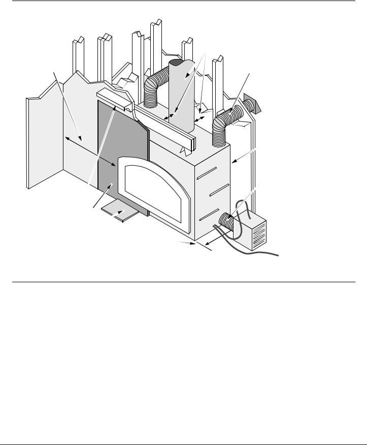
Installation Overview
•All requirements below must be met.
See the section "Minimum Clearances"
18" Min.
See the section "Mantel Requirements"
See the section "Facing Requirements"
See the section |
|
"Hearth Requirements" |
See the section |
|
"Minimum Framing |
|
Dimensions" |
See the section "Chimney Requirements"
See the section
"Cooling Vent Requirements"
Insulation must not fill the spaces between the stand-offs
See the section "Blower Requirements"
Figure 3
Recommended Order of Installation
•Frame the opening for the fireplace. Make sure to allow for vent, blower, and cooling vent installation.
•Secure the fireplace to the floor.
•Install the vent, blower, cooling vents, and electrical hook-up.
•Complete the framing above the fireplace.
•Install the hearth.
•Install the facing.
•Install the mantel.
•Finalize the installation (see the instructions starting on page 26).
© Travis Industries |
4090921 |
93508093 |

8 |
Installation (for qualified installers only) |
Installation Requirements for Cold Environments
If you live in the area depicted in black (see Figure 4), you must Install a cooling air “P” trap as detailed below and install the blower on an internal wall. In addition, make sure the homeowner follows the requirements shown below to help minimize cold air being pulled into the fireplace when it is not in use.
Install the Blower in an Internal Location
In cold environments the blower must be positioned on an internal wall (see Figure 5). This eliminates any chance of any outside air being drawn into the convection chamber from the blower location.
NOTE: Do not place the blower inside a garage or other area that may circulate fumes.
Figure 4
|
Internal Blower |
Exterior |
Exterior Wall |
Fireplace |
|
|
Interior of Home |
Figure 5
Cooling Air “P” Trap
Min. 24"
Max. 48"
When installing the cold air ducts, make sure to include a “P” trap in the design (see the illustration to the right). This helps slow cold air from circulating through the cooling air chamber.
Fireplace
Xtrordinair
Daily Requirements for Homeowners
Min. 24"
Max. 48"
|
|
|
|
|
Humidity |
|
|
Figure 6 |
|
Make sure the humidistat is set correctly. The chart below details the correct setting for the temperature you are experiencing outdoors.
Outdoor Temperature |
|
Recommended Humidity |
° F |
° C |
Controller Setting |
|
|
|
-20 |
-29 |
15 |
-10 |
-23 |
20 |
0 |
-18 |
25 |
+10 |
-12 |
30 |
+20 |
-7 |
35 |
>+20 |
>-7 |
40 |
Note: If using a humidifier, let the homeowner know that it should be shut off or turned to a lower setting to eliminate condensation.
Other Items
•Make sure the bypass is shut when the fireplace is not in use.
•Minimize the use of exhaust fans in the home when the fireplace is not in use.
© Travis Industries |
4090921 |
93508093 |

Installation (for qualified installers only) |
9 |
Negative Pressure Warning
The Fireplace Xtrordinair wood fireplace relies upon natural convection to supply cooling air to the fireplace. If installed into a house experiencing negative pressure, air may be pulled into the fireplace. This leads to the face becoming cold while the fireplace is not in use, and in severe cases, air being pulled into the room.
What Causes Negative Pressure
Today’s air-tight homes are not 100% air tight. If air leaks are found at the top of the home enclosure, air may be pulled through the home due to convection (the warmer air moves upwards, leaving the home, causing air to be pulled into the home from different location). See Figure 7 below.
Recessed lighting in ceilings may allow air to infiltrate into the attic, leading to negative pressure.
Heated air, leaving the house in cracks near the ceiling contribute to negative pressure.
Driers or range fans contribute to negative pressure.
Cracks near doors or windows can contribute to negative pressure.
Air can be pulled down the chimney, into the firebox.
The cooling air* can be heated by the house, causing syphoning. This pulls cool air through the cooling channel, leading to fireplace cooling.
*Cooling air is required by the fireplace to prevent overheating.
Negative pressure can cause air to be pulled through the blower, through the duct, through the
 fireplace convection channel and into the house.
Figure 7
How to Measure Negative Pressure
Digital pascal meters (also called “pressure meters”, digital “manometers”) can measure negative pressure readings inside a home. They typically cost around $600. They measure pascals (1 pascal is equal to
.004” Water Column). Typical homes have 0 to -1 pascals. Homes with negative pressure have -2 or more (we have measured homes with upwards of -8 pascals). We strongly recommend measuring the pressure in homes suspected of encountering negative pressure. This allows the homeowner, and fireplace installer, to view an objective measurement.
How to Remedy Negative Pressure
The only proven method to reduce negative pressure is to install an “air exchanger”. This device allows outside air to enter the home after going through a “heat exchanger” to minimize cold infiltration.
© Travis Industries |
4090921 |
93508093 |

10 |
Installation (for qualified installers only) |
Fireplace Placement Requirements
Minimum Framing Dimensions
The fireplace enclosure must not be
less than 81" above the base of the fireplace.
• If the fireplace is raised, the enclosure height must be raised to
maintain the 81".
•Do not build into this area.
•Do not slope the walls inward.
50-1/2"
26"
50"
Framing Dimensions at 45
25" 25"
Fireplace (includes
1/2"
standoffs)
26"
72"
49"
A firestop is required at the top of the fireplace enclosure or ceiling
level (whichever is lower).
Min. 4-1/2"
We recommend installing the
shaded framing members after installing the chimney.
Arrange the framing members so there is not a
vertical member directly in the center of the opening
where it would interfere with pipe clearances.
Header
(install veritcally to ensure proper pipe to
header clearance)
NOTE: make sure the enclosure is wide enough to
accommodate the blower (see the section"Blower" for
details).
Figure 8
27"
Figure 9
© Travis Industries |
4090921 |
93508093 |
 Loading...