

FireplaceXtrordinair 36 ELITE-ZC Installation Manual
TM
• Zero Clearance
Fireplace
36 ELITE-ZC INSTALLATION MANUAL
10850 117th Place N.E. Kirkland, WA 98033
Listed
Tested to:
U.L. 127 and porti ons
of U.L. 1482 & 907
Part # 93508090 4020405 $10.00

P AGE 2 TABLE OF CONTENTS
Features & Specifications
Features:.........................................................................................1
Installation Options: ...........................................................................1
Heating Specifications........................................................................1
Dimensions......................................................................................1
Installation
Installation Preparation.......................................................................2
Packing List .....................................................................................2
Fireplace Placement Requirements.......................................................3
Minimum Framing Dimensions..........................................................3
Clearances ...................................................................................4
Corner Installation ..........................................................................4
Raised Fireplaces...........................................................................5
Facing Requirements.........................................................................5
Mantel Requirements.........................................................................7
Hearth Requirements.........................................................................7
Cooling Vents...................................................................................8
Blower.............................................................................................9
Blower Duct Connection ..................................................................9
Blower Electrical Connection ............................................................10
Chimney..........................................................................................11
Chimneys Part Numbers..................................................................11
Chimney Connection to Fireplace ......................................................11
Chimney Height .............................................................................12
Special Chimney Requirements.........................................................12
Using Offsets.................................................................................13
Clearances to Combustibles.............................................................14
Firestops ......................................................................................14
Framing the Roof ...........................................................................15
Chimney Termination Requirements...................................................15
Finalizing the Installation.....................................................................16
Listing Information
Safety Label.....................................................................................21
Index
Index ..............................................................................................22
Symbols Used in this Manual
The illustration below details what the symbols used along the left margin indicate.
Requirement
•1!?+
NoteWarningStep
Hint
FEATURES AND SPECIFICATIONS PAGE 3
A
D
Features:
• EPA Phase II approved (2.3 g/hr.)
• Maximum Log Length of 24"
• Large firebox capacity - 3.7 cu. ft.
• Long burn time - up to 10 Hours.
• Large glass doors for maximum visibility.
• Firebrick lining for firebox protection.
• 388 CFM blower for convection heat and outside
Installation Options:
• Straight or Corner Placement
• Flush or Recessed Face
• Raised or Flush Floor Hearth
• Internal or External Chase
• 8' leads for the power source and the blower
(120 Volts A.C.)
• Set-up face is included to ease facing installation
• 3 blower duct locations for a wide selection of
interior or exterior blower installation options
combustion air.
• Thermostat for automatic control of the blower.
Heating Specifications
Approximate Heating Capacity (in square feet)* 1,200 - 2,500
Maximum Burning Time Up to 10 Hours
BTU Output per Hour (Cord Wood Method) 10,300 to 66,000
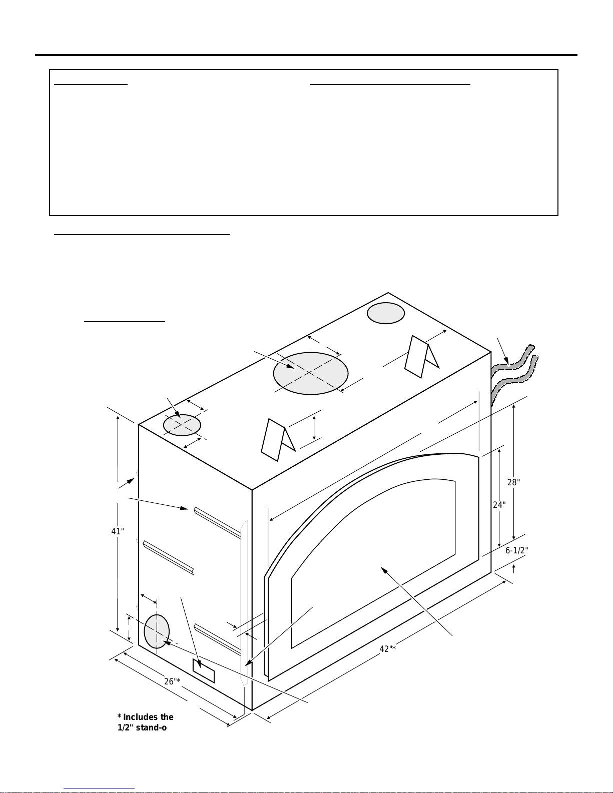
imensions:
Weight: 590 Lbs.
Cooling vents
have an external
diameter of 6"
See "Chimney
Requirements"
4"
11"
20-1/2"
* Will vary with the home's
floor plan, insulation, and
outside temperature.
Electrical
Conduit
Location
1/2"
Stand-offs
41"
Optional Electrical
7-5/8"
Conduit Exit Location
3-1/4"
26"*
26-1/2"*
* Includes the
1/2" stand-offs
4"
4"
1-1/2" Wide Nail
Down Flange
1"
42"*
6" Blower hook-ups are on both sides and on the bottom
(centered 7-5/8" from the rear edge). Remove the cover
plate to access the blower hook-up.
36"
28"
24"
6-1/2"
The set-up face shipped on the
fireplace is 36-1/8" wide and
28-1/16" tall (dimensions
shown are for the finished face)
PAGE 4 INSTALLATION
Installation Preparation
! Read this entire manual before installing the fireplace.
! Failure to install this fireplace in accordance with all local codes and the requirements listed in this
manual may result in property damage, bodily injury, or even death.
! Notify your insurance company before installing this fireplace.
! The requirements listed below are divided into sections. All requirements must be met
simultaneously. The order of installation is not rigid – the qualified installer should follow the
procedure best suited for the installation.
! Modifications of the fireplace (doors, blower, air inlet systems, damper control, or any other
component supplied by Travis Industries) or use of any component part not approved by Travis
Industries in combination with this fireplace system will void the listing and warranty.
Packing List
Shipped with the Fireplace:
• Installation Manual
• Grate
• Baffle
• Blower Assembly
• Ember Strip
• Log Retainer (includes allen wrench & instructions)
• Flex Duct w/ start collar – 3' Length, 6" Dia (For Blower)
• Two 10' Flex Ducts, 6" Diameter (For Cooling Vents)
• Two Vent Hoods (For Cooling Vents)
• Two Vent Hood Storm Collars (For Cooling Vents)
Shipped with the Faceplate:
• Faceplate (two switch plate screws are attached)
• Switch Plate (includes blower rheostat)
• 10 Faceplate Screws
Shipped with the Door(s):
• Owner's Manual
• Installation Hardware Pack
• Pair of Gloves
• Efficiency and Registration Cards
• Touch-up Paint
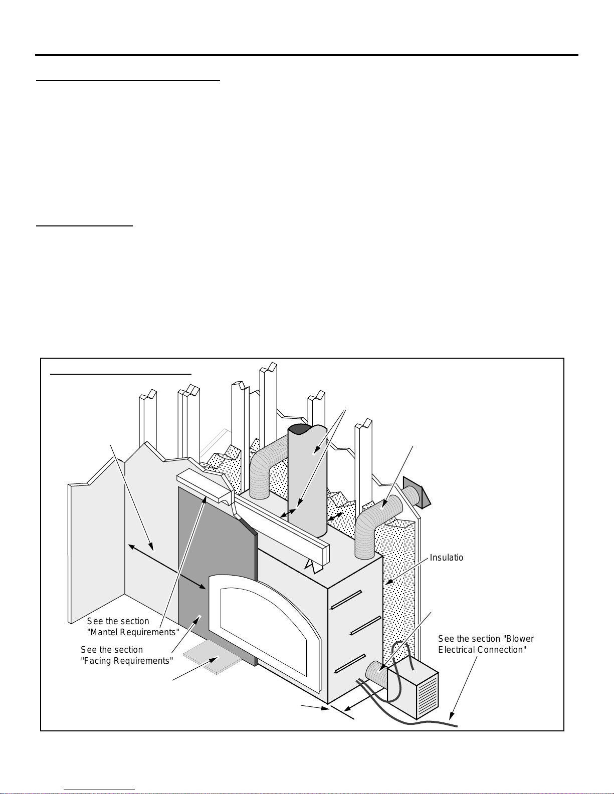
Installation Overview
See the section
"Fireplace
Placement
Requirements"
18" Min.
See the section
"Mantel Requirements"
See the section
"Facing Requirements"
See the section
"Chimney Requirements"
See the section
"Cooling Vent Installation"
Insulation must not fill the
spaces between the stand-offs
See the section
"Blower Duct Connection"
See the section "Blower
Electrical Connection"
See the section
"Hearth Requirements"
See the section
"Minimum Framing
Dimensions"
INSTALLATION (CONTINUED) PAGE 5
Fireplace Placement Requirements
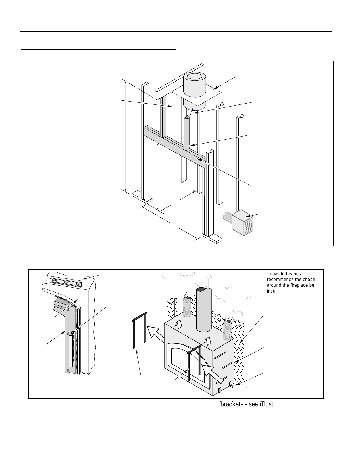
Minimum Framing Dimensions
A firestop is required at the top of
the fireplace enclosure or ceiling
level (whichever is lower).
The fireplace enclosure must not be
less than 81" above the base of the
fireplace.
• If the fireplace is raised, the
enclosure height must be raised to
maintain the 81".
• Do not build into this area.
• Do not slope the walls inward.
• The header, vertical framing
members, and all interior wall
surfaces may protrude a maximum
4" into this area.
45-1/2"
26"
43"
Min. 4-1/2"
We recommend installing the
shaded framing members
after installing the chimney.
Arrange the framing
members so there is not a
vertical member directly in
the center of the opening
where it would interfere with
pipe clearances.
Header
(install veritcally to
ensure proper pipe to
header clearance)
NOTE: make sure the
enclosure is wide enough to
accommodate the blower
(see the section"Blower" for
details).
• The fireplace uses 1/2" standoffs on the back and sides and 4" stand-offs on the top to space the
fireplace away from framing members or walls. These stand-offs may contact the framing members or
walls but do not place insulation or other material in the space between the stand-offs and fireplace.
The fireplace (and
firebox) must be made
level and plumb during
installation. Use shims
under the fireplace to
properly level the
fireplace.
Zero
Clearance
Can
Travis Industries
recommends the chase
around the fireplace be
insulated. This insulation
should only be placed
between the framing
members and secured so
it does not fill the space
between the fireplace and
standoffs.
Firebox
WARNING:
Failure to correctly level and plumb
this fireplace will lead to doors that
swing open or closed.
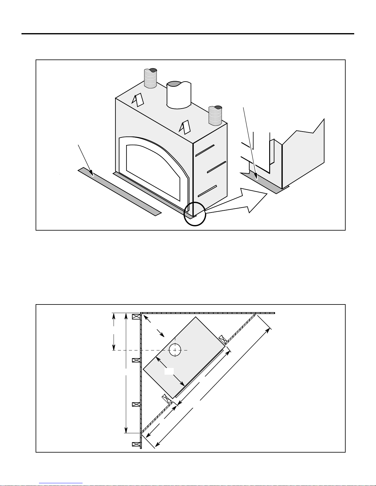
• The fireplace must be secured to the floor (use the lifting handle brackets - see illustration above).
• Fireplace must be placed directly on wood or non-combustible surface (not on linoleum or carpet)
These lifting handles are
removed (use a 7/16" wrench)
once the fireplace is in place.
Standoffs (also
located on back)
Bend this bracket down
on each side and nail it
to the floor, securing the
fireplace in position.
PAGE 6 INSTALLATION (CONTINUED)
9
• Fireplace must be installed on a level surface capable of supporting the fireplace and chimney
• Place the ember strip included with the fireplace below the front edge of the fireplace.
EMBER STRIP
INSTRUCTIONS
Place this ember
strip under the front
of the fireplace and
the back edge of the
hearth.
NOTE: On the 36 ZC,
36 BI, and 44 BI the
ember strip will need to
be shortened.
The ember strip
insures no ember falls
between the fireplace
and hearth onto the
combustible floor.
Clearances
• When installed, walls in front of the fireplace must be a minimum 18" to the side of the faceplate (or
15-1/2" from the side of the fireplace) – see the illustration on page 2
• Fireplace should be located such that no doors, drapes, furniture or other combustibles can be placed
close or swing closer than the minimum 36" clearance. Due to the high heat output of this fireplace,
choose a location away from high traffic areas.
• Fireplace must be placed so the vents below and above the glass do not become blocked
Corner Installation (minimum framing dimensions at 45°)
22-1/4"
66-1/2"
20-1/2"
Fireplace
(includes
1/2"
standoffs)
26"
42"
3"
26"
INSTALLATION (CONTINUED) PAGE 7
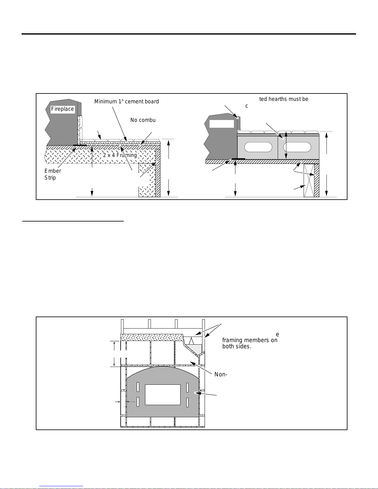
Raised Fireplaces
• If the fireplace is raised more than 15” above the sub-floor, the fireplace
enclosure will have to be raised accordingly (see “Minimum Framing
Dimensions” on page 3).
+ The fireplace may be placed on a platform designed to support the fireplace and vent
(Approximately 600 Lbs.).
Elevated hearths must be
constructed of non-combustible
materials such as cement blocks
(6-1/2” Max.).
3/4"
Plywood
2 x 8 Framing
Fireplace
Ember
Strip
Minimum 1" cement board
Tile or
marble
2 x 4 Framing
Header height will
need to be increased
this dimension.
No combustible material
permitted above this point
Tile or
marble
15"
Raised
3/4"
Plywood
hearth
Faceplate
Fireplace
Ember
Strip
Header height needs to be
increased this dimension.
Facing Requirements
NOTE: Artisan faces vary in size. If the facing is over 1” thick (brick, river-
rock, etc.) use the face being installed to create a template.
• The fireplace is shipped with a set-up face that is 1/16" larger on the top, bottom and each side than
the faceplate. Leave the set-up face in place to act as a template when installing the facing.
• The fireplace requires 1/2" thick concrete-board or other non-combustible to extend from the header
to the base of the fireplace and to the framing members on both sides (do not use sheetrock or
drywall).
• The non-combustible facing must extend a minimum of 12" above and 2-1/2" to each side of the
faceplate.
• The non-combustible facing must be a minimum 1" thick
• The facing may be attached to the front of the fireplace with screws. Do not penetrate the fireplace
more than 3/4”.
15"
Raised
hearth
12" (min.)
2-1/2"
(min.)
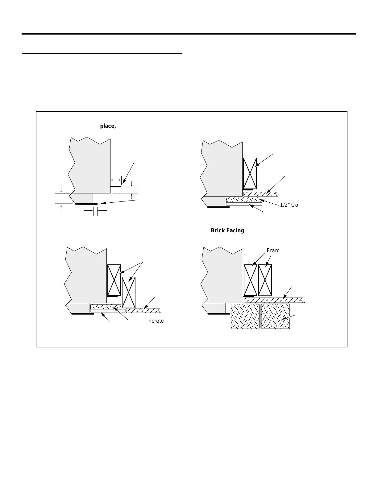
• Facing may be installed so it inserts behind the faceplate. NOTE: the faceplate protrudes 1" from the
front of the fireplace, has a 1/8" overlap on the sides, and 1/4" overlap on top.
Cement-board must
extend from the header
to the floor and to the
framing members on
both sides.
Non-combustible
Facing
Keep the set-up face
on the fireplace when
installing the facing.
PAGE 8 INSTALLATION (CONTINUED)
Facing Requirements (continued)
• The combustible area above the facing must not protrude more than 3/4" from the facing. If it does,
it is considered a mantel and must meet the mantel requirements listed in this manual.
•+ To achieve a facing that is flush with the drywall to the side of the fireplace, recess the framing
directly next to the fireplace. See the illustration below.
TOP VIEW
(cross section of fireplace, framing, and face)
Nail Down Flange
(used to secure the
fireplace to the framing)
Fireplace
1-1/2"
1/2"
1"
1/8" (1/4" overalap on
top, 0" on bottom)
Flush Facing
Fireplace
Faceplate
Framing
1/2" Drywall
Overlapped Facing
Fireplace
Brick Facing
Fireplace
Framing
1/2" Drywall
1/2" Concrete Board
3/8" Tile
Framing
1/2" Drywall
3/8" Tile
Brick
1/2" Concrete Board
 Loading...