

FireplaceXtrordinair 2000 36 DV XL Owner's Manual
TM
Tested and Listed by
• Built-In Direct Vent Fireplace
• Natural Gas or Propane
• Residential or Mobile Home
WARNING: Improper installation, adjustment, alteration, service or maintenance can cause
injury or property damage. Refer to this manual. For assistance or additional
information consult a qualified installer, service agency, or the gas supplier.
- Do not store or use gasoline or other flammable vapors and liquids in the vicinity of this or
any other appliance.
- Inst allation mus t be perf or m ed by a qualified installer, s er v ic e agenc y or the gas supplier
IF YOU SMELL GAS
• Do not try to light any appliance.
• Do not touch any electrical switch; do not use any phone in your building.
• Immediately call gas supplier from a neighbor's phone. Follow the gas supplier's instructions.
• If you cannot reach your gas supplier, call the fire department.
Omni-Test Laboratories, Inc.
Beaver ton, Oregon
R eport # 028- S-20-1
ANSI Z 21.88, CSA 2. 33 MR 8,
CAN/ CGA 2.17-M 91
2000 36 DV XL Owner’s Manual
- September, 2000 -
Installer: After installation give this manual to the home-
owner and explain operation of this fireplace.
$10.00 Copyright 2000, T.I. Part # 93508118
10850 117th Place N.E. Kirkland, WA 98033

2 Safety Precautions
• IF YOU SMELL GAS:
* Do not light any appliance
* Extinguish any open flame
* Do not touch any electrical switch or plug or unplug anything
* Open windows and vacate building
* Call gas supplier from neighbor's house, if not reached, call fire
department
• This unit must be installed by a qualified installer to prevent the possibility of an
explosion. Your dealer will know the requirements in your area and can inform you of
those people considered qualified. The room heater should be inspected before use
and at least annually by a qualified service person. More frequent cleaning may be
required due to excessive lint from carpeting, bedding material, etc.
• The instructions in this manual must be strictly adhered to. Do not use makeshift
methods or compromise in the installation. Improper installation will void the warranty
and safety listing.
Ok
Look for this label:
For LPG only | Pout 11” W.C.
If the label is present, the
heater is equipped for LP
(propane). If the label is
absent, the heater is equipped
for NG (natural gas).
• Contact your local building
officials to obtain a permit
and information on any
installation restrictions or
inspection requirements in
your area. Notify your
insurance company of this
heater as well.
• It is imperative that control
compartments, screens, or
circulating air passageways
of the heater be kept clean
and free of obstructions.
These areas provide the air
necessary for safe
operation.
• This heater is either approved for natural
gas (NG) or for propane (LP). Burning the
incorrect fuel will void the warranty and
safety listing and may cause an extreme
safety hazard. Direct questions about the
type of fuel used to your dealer. Check
the label and flame adjust knob on the
gas control valve.
• If the flame becomes sooty,
dark orange in color, or
extremely tall, do not
operate the heater. Call
your dealer and arrange for
proper servicing.
• Do not operate the heater if
it is not operating properly in
any fashion or if you are
uncertain. Call your dealer
for a full explanation of your
?
heater and what to expect.
• Do not store or use gasoline
or other flammable liquids in
the vicinity of this heater.
Gas
Travis Industries 93508118 270900
• Do not operate if any portion
of the heater was
submerged in water or if any
corrosion occurs.

Safety Precautions 3
• Do not place clothing or
other flammable items on or
near the heater. Because
this heater can be controlled
by a thermostat there is a
possibility of the heater
turning on and igniting any
items placed on or near it.
• The viewing glass should be
opened only for lighting the
pilot or conducting service.
• Any safety screen or guard
removed for servicing must
be replaced prior to
operating the heater.
• Operate the heater
according to the instructions
included in this manual.
• If the main burners do not
start correctly turn the gas
off at the gas control valve
and call your dealer for
service.
• Light the heater using the
built-in piezo igniter. Do not
use matches or any other
external device to light your
heater.
• Never remove, replace,
modify or substitute any part
of the heater unless
instructions are given in this
manual. All other work must
be done by a trained
technician. Don't modify or
replace orifices.
• Allow the heater to cool
before carrying out any
maintenance or cleaning.
• The pilot flame must contact
the thermopile and
thermocouple (see the
illustration to the left). If it
does not, turn the gas
control valve to "OFF" and
call your dealer.
• This unit is not for use with
solid fuel
• Do not place anything inside
the firebox (except the
included fiber logs).
• If the fiber logs become
damaged, replace with
Travis Industries log set.
• Do not touch the hot
surfaces of the heater.
Educate all children of the
danger of a hightemperature heater. Young
children should be
supervised when they are in
the same room as the
heater.
• Instruct everyone in the
house how to shut gas off to
the appliance and at the gas
main shutoff valve. The gas
main shutoff valve is usually
next to the gas meter or
propane tank and requires a
wrench to shut off.
This
Manual
36"
• Do not throw this manual
away. This manual has
important operating and
maintenance instructions
that you will need at a later
time. Always follow the
instructions in this manual.
• Keep all furniture or other
combustible items at least
36" away from the front of
the fireplace (this includes
drapes or doors that may
swing within 36" of the front
of the fireplace).
• Travis Industries, Inc.
grants no warranty,
implied or stated, for
the installation or
maintenance of your
heater, and assumes
no responsibility of any
consequential
damage(s).
Travis Industries 93508118 270900

4 Table of Contents
Introduction
Introduction & Important Information................1
Safety Precautions
Safety Precautions ......................................2
Features & Specifications
Features ....................................................5
Installation Options ......................................5
Heating Specifications ..................................5
Dimensions.................................................5
Installation
Installation Warning......................................6
Packing List................................................6
Additional Items Required for Installation..........6
Installation Overview ....................................6
Fireplace Placement Requirements..................7
Minimum Framing Dimensions ....................7
Clearances ............................................7
Corner Installations.................................8
Raised Fireplaces....................................8
Hearth Requirements....................................9
Facing Requirements....................................10
Facing Over 1" Thick.....................................10
Facing Detail...............................................11
Face Dimensions .........................................12
Rectangular Faces.......................................12
Facing and Hearth Examples..........................13
Mantel Requirements....................................15
Vent Requirements.......................................16
Altitude Considerations ............................16
Clearances ............................................16
Use of 8” Dia. Pipe...................................16
Part Numbers for 6-5/8" Dia. Pipe................16
Vent Installation......................................17
Approved Vent Configurations........................18
Restrictor Position...................................18
Elbows ..................................................18
Measuring Vent Lengths...........................18
Vertical Term. 0,2 or 4 45° Offsets (6-5/8")....19
Hor. Terminations with 6-5/8" Dia. Vent ........20
Vert. Term. with 2 or 3 Elbows (6-5/8" Dia.)....21
Horizontal Terminations with 8” Dia. Vent......22
Vent Termination Requirements ......................23
Gas Line Requirements.................................24
Fuel......................................................24
Gas Line Connection................................24
Gas Inlet Pressure ..................................24
Electrical Connection....................................25
Finalizing the Installation
1 Glass Removal (& installation)......................26
2 Log & Coal Installation................................27
3 Replace the Glass .....................................30
4 Faceplate Installation .................................30
5 Leak Test.................................................30
6 Pilot Adjustment (if necessary).....................30
7 Air Shutter Adjustment (if necessary)............31
8 Check Flame.............................................31
9 Explain Operation to Home-Owner.................31
Operation
Before You Begin.........................................32
Location of Controls .....................................32
Starting The Pilot .........................................33
Starting the Fireplace for the First Time.............34
Turning the Fireplace On and Off.....................34
Adjusting the Flame Height.............................34
Adjusting the Blower Speed............................35
Normal Operating Sounds..............................35
Maintenance
Yearly Service Procedure ..............................36
Troubleshooting Table...................................37
How this Fireplace Works...............................38
What Turns the Main Burners On and Off......38
What Prevents Gas Buildup.......................38
Wiring Diagram ............................................39
Replacement Parts List .................................39
Safety Label
Safety (Listing) Label....................................40
Warranty
Warranty ....................................................41
Optional Equipment
LP Conversion Kit ........................................42
Power Heat Duct..........................................46
Thermostat.................................................52
Remote Control Thermostat............................53
Decorative Refractories (Classic & Brick) .........53
Index
Index.........................................................54
Travis Industries 93508118 270900

Features and Specifications 5
l
n
r
Features:
- Works During Power Outages (millivolt system)
- High Efficiency
- Optional Thermostat or Remote Control
- Realistic "Wood Fire" Look
- Quiet Blower for Effective Heat Distribution
- Convenient Operating Controls
- Variable-Rate Heat Output
Installation Options:
- Residential or Mobile Home
- Straight or Corner Placement
- Flush or Recessed Face
- Raised or Floor Hearth
- Internal or External Chase
- Horizontal or Vertical Vent
- Power Heat Duct
- Low Maintenance
Heating Specifications:
Natural Gas Propane
Approximate Heating Capacity (in square feet)* 1,200 - 2,250 1200 - 2,250
Maximum BTU Input Per Hour 43,000 43,000
Minimum BTU Output on Low (with blowers on) 23,384 20,800
Efficiency** (with blowers on) Up to 79% Up to 80%
AFUE (Annual Fuel Utilization Efficiency) 72 % 73 %
* Heating capacity will vary with floor plan, insulation, use of Power Heat Duct, and outside temperature.
** Efficiency rating is a product thermal efficiency rating determined under continuous operation
independent of installed system.
Dimensions:
Weight: 250 Lbs.
3-1/4"
Power
Heat Vent
Hook-Up
Vent has an
external diameter
of 6-5/8"
25-3/4"*
7-7/8"
7-7/8"*
6-1/4"
connection is made i
the lower right rea
6-3/4"
The electrica
corner.
3-3/4"
1-7/8"
6-1/4"
21-1/2"
23"
26-3/4"
1"
1"
Gas Inlet (on both sides)
35-1/4"
43"*
* Includes the
1/2" stand-offs
1/2" Stand-offs
Nail Down
Plate (used
to secure
the fireplace
to the floor)
40"
19-5/8"*
6-5/8"
Travis Industries 93508118 270900

6 Installation (for qualified installers only)
Installation Warnings:
! Failure to follow all of the requirements may result in property damage, bodily
injury, or even death.
! This heater must be installed by a qualified installer who has gone through a
training program for the installation of direct vent gas appliances.
! This appliance must be installed in accordance with all local codes, if any; if not, in
U.S.A. follow ANSI Z223.1 and NFPA 54(88), in Canada follow B-149.
! In Manufactured or Mobile Homes must confirm with: In USA, Manufactured Home
Construction and Safety Standard, Title 24 CFR, Part 3280; In Canada, CSA Z240.4
and Gas-Equipped Recreational Vehicles and Mobile Housing. This appliance may
be installed in Manufactured Housing only after the home is site located.
! The 36DV is designed to operate on natural gas, or propane (LP).
All exhaust gases must be vented outside the structure of the living-area.
Combustion air is drawn from outside the living-area structure.
! Notify your insurance company before hooking up this fireplace.
! The requirements listed below are divided into sections. All requirements must be
met simultaneously. The order of installation is not rigid – the qualified installer
should follow the procedure best suited for the installation.
Packing List
• Propane Conversion Kit
• Log Set (Log Set & Coals)
• Electrical Connector (3 wires - female molex)
• Flex Tube with Pipe Adapter
• Glass Latch Tool (to un-latch glass frame)
• Arch Covers (for arched faces only)
Installation Overview
See "Power Heat
Vent" in the optional
equipment section.
4-1/2" Min.
Drywall
Additional Items Required
• Faceplate (gold or black) - Includes attachment screws
• Direct Vent (Simpson Dura-Vent Ph. # 800 835-4429)
• Gas Line Equipment (shutoff valve, pipe, etc.)
• Electrical Equipment (min. 18 gauge, grounded line)
See the section
"Vent Requirements"
See the section
"Horizontal Termination
Requirements"
See the
section
"Acceptable
Vent Lengths"
Non-combustible facing
(see the section "Facing
Requirements")
See the section
"Mantel Requirements"
See the section
"Hearth Requirements"
Travis Industries 93508118 270900
See the section "Fireplace
Placement Requirements"
Nail
Down
Plate
See the section
"Gas Line Installation"
Insulation must not fill
the spaces between
the stand-offs
See the section
"Electrical
Connection"
See the section "Minimum
Framing Dimensions"
Installation (for qualified installers only) 7
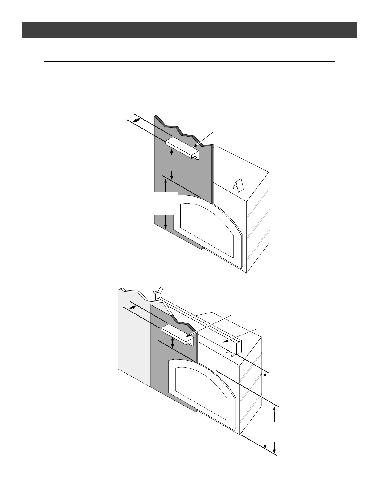
Fireplace Placement Requirements
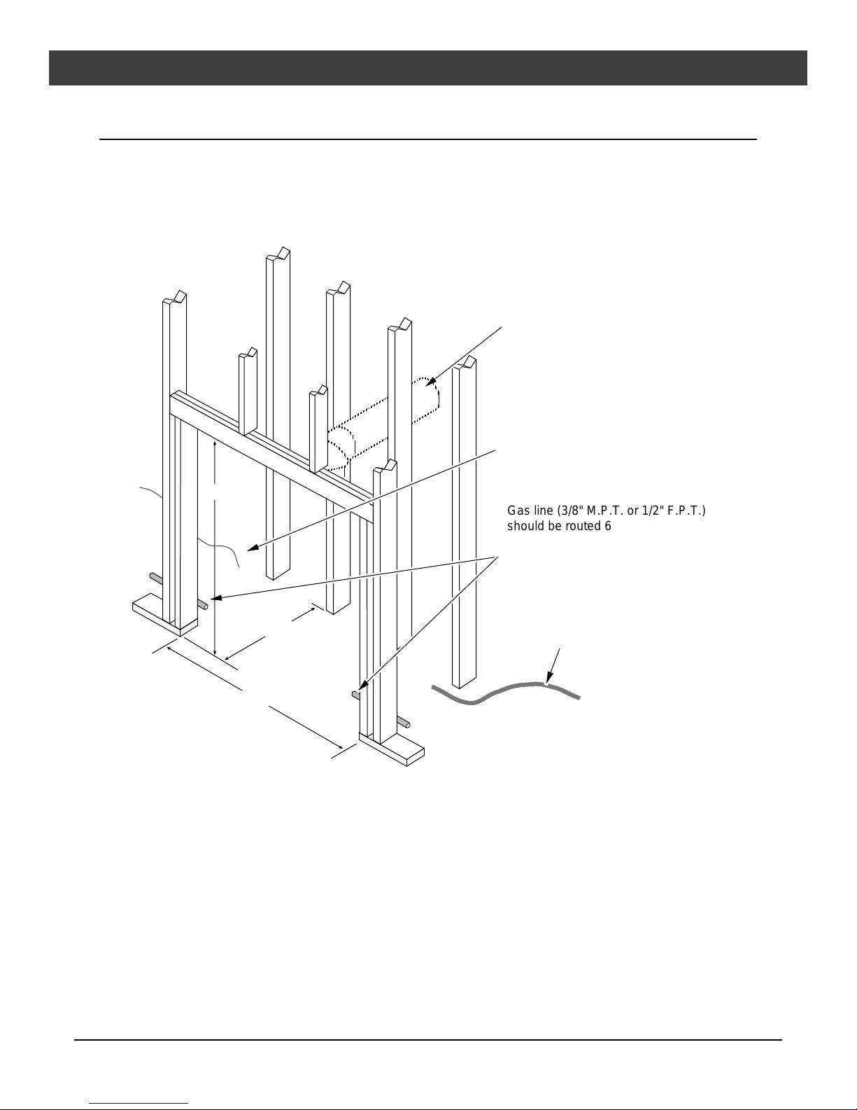
Minimum Framing Dimensions
The 1/2" stand-offs on the back and sides and 6-1/4" stand-offs on the top of the fireplace are
designed to separate the fireplace from the framing members. These stand-offs may contact the
framing members but no material may be placed between the stand-offs.
NOTE: if venting directly to the rear,
make sure there is a min. 8-5/8" space
centered behind the fireplace for the
wall thimble. If a 90° elbow is used
directly off of the fireplace, the thimble
will be centered 51-1/4" above the
base of the fireplace.
If using a remote control or
thermostat, route the wire to a
location near the gas line (include
an extra 3' length for hookup).
46-1/2"
Gas line (3/8" M.P.T. or 1/2" F.P.T.)
should be routed 6-5/8" behind the
framing opening and 1-7/8" above
the base of the fireplace (see "Gas
Line Connection" for details).
19-5/8"
43-1/4"
Route the electrical line to a position
at the right rear of the fireplace.
NOTE: If using the power heat vent,
allow for the duct passage when
framing the enclosure.
• Fireplace must be installed on a level surface capable of supporting the fireplace and vent
• Fireplace must be placed directly on wood or non-combustible surface (not on linoleum or carpet)
• Due to the high temperature of the fireplace, it should be located out of traffic and away from furniture
and draperies.
• This heater may be placed in a bedroom. Please be aware of the large amount of heat this appliance
produces when determining a location.
Clearances
• When installed, walls in front of the fireplace must be a minimum 4-1/2" to the side of the faceplate.
• Fireplace must be placed so that no combustibles are within, or can swing within 36" of the front of the
fireplace (e.g. drapes, doors)
• Fireplace must be placed so the vents below and above the glass do not become blocked
Travis Industries 93508118 270900
8 Installation (for qualified installers only)
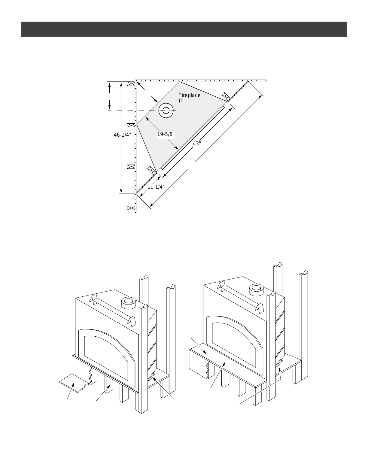
Corner Installations
A typical 45° installation uses the minimum framing dimensions shown in the illustration below (NOTE:
all clearances still apply).
14-1/2"
46-1/4"
12-3/4"
19-5/8"
11-1/4"
Fireplace
(includes
1/2"
standoffs)
43"
65-1/2"
Raised Fireplaces
• The fireplace (and hearth, if desired) may be placed on a platform designed to support the fireplace
(250 Lbs.) and vent.
• The fireplace may not be raised so as to place the ceiling within 24" of the top of the faceplate.
Raised fireplace
Hearth
Raised
Platform
Raised fireplace with
raised hearth.
Raised
Platform
Raised Hearth
Nail the nail down plates to the floor
(or raised platform)
Travis Industries 93508118 270900
Installation (for qualified installers only) 9
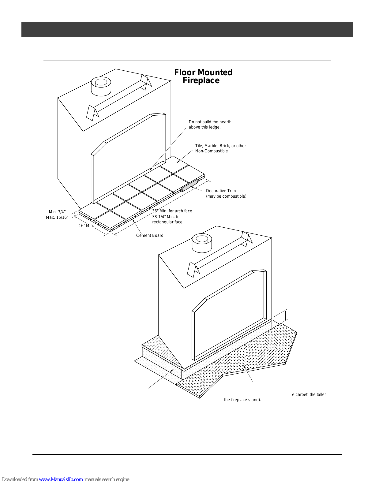
Hearth Requirements
Floor Mounted
Fireplaces
Do not build the hearth
above this ledge.
Tile, Marble, Brick, or other
Non-Combustible
Decorative Trim
(may be combustible)
Min. 3/4”
Max. 15/16”
16” Min.
Cement Board
Raised
Fireplaces
Fireplace Stand
36" Min. for arch face
38-1/4" Min. for
rectangular face
When raised a minimum of
3” off of the floor surface,
no hearth is required.
Make sure to accomodate the floor covering (carpet,
linoleum, flooring, etc.) when determining the height of
the fireplace stand (i.e. the thicker the carpet, the taller
the fireplace stand).
Travis Industries 93508118 270900
10 Installation (for qualified installers only)
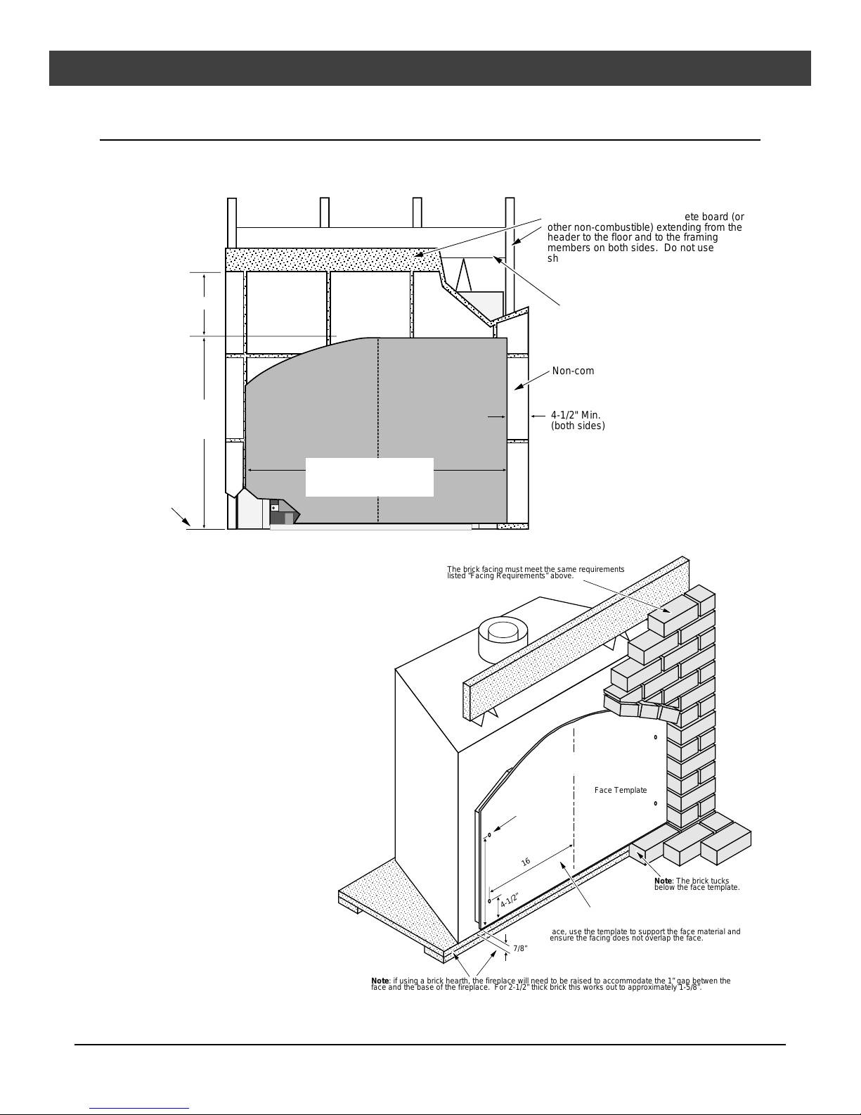
Facing Requirements
NOTE: The combustible area above the facing must not protrude more than 3/4" from the facing. If it
does, it is considered a mantel and must meet the mantel requirements listed in this manual.
The fireplace requires a concrete board (or
other non-combustible) extending from the
header to the floor and to the framing
members on both sides. Do not use
sheetrock, plywood or other combustible.
10" Min.
28-1/2" Rectangular face
30-3/8" Architectural face
30" Arch face
Base of
Fireplace
Facing Over 1"
Thick
• Architectural faces
require a 5/8" gap
above the face for face
installation.
• If the facing material is
over 1" thick (e.g. brick,
river rock), install the
facing around the
perimeter of the face.
You may wish to make a
face template (see the
illustration to the right).
If using an arch face,
you may wish to order
the optional set-up
face:
Arch Set-Up Face
Part # 98500692
• For rectangular faces,
use a piece of plywood
cut to the dimensions
shown on page 12
(add 1/8" to each
dimension).
Arch Face
36" Arch face
38" Rectangular face
36-1/4" Architectural face
Header
Rectangular Face
The brick facing must meet the same requirements
listed “Facing Requirements” above.
Mounting
Holes
19-3/4”
4-1/2”
Note: if using a brick hearth, the fireplace will need to be raised to accommodate the 1” gap betwen the
face and the base of the fireplace. For 2-1/2” thick brick this works out to approximately 1-5/8”.
Non-combustible Facing
4-1/2" Min.
(both sides)
Center
Line
Face Template
16-3/8”
Note: The brick tucks
below the face template.
The face template should be 1/8” larger than the
finished face. Attach the template to the fireplace using
the face attachment screws. Then while building the
face, use the template to support the face material and
ensure the facing does not overlap the face.
7/8”
Travis Industries 93508118 270900
Installation (for qualified installers only) 11
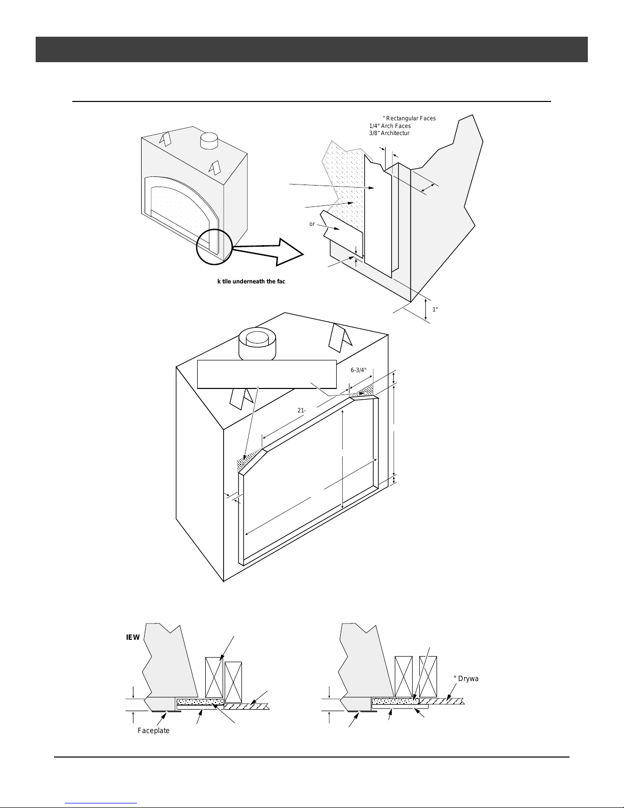
Facing Detail
NOTE:
The overlap is 1-1/2" along
the top of the face.
Face
Glass
Access Door
Air Space
Do not tuck tile underneath the face on the bottom (there
will be a 1/2" air space below the access door). You may
do this on the sides and top, but not on the bottom.
Make sure these shaded areas are faced over
when using the arched face. Rectangular faces
do not require this area to be faced.
21-1/2"
1-3/8” Rectangular Faces
1/4" Arch Faces
3/8” Architectural Faces
1/2"
6-3/4"
1"
1"
3-3/4"
23"
26-3/4"
1"
1"
35-1/4"
• To achieve a facing that is flush with the drywall to the side of the fireplace, recess the framing directly
next to the fireplace. See the illustration below.
TOP
VIEW
1"
Fireplace
Faceplate
3/8" Tile
This 2x4 is recessed 3/8"
to make a flush facing
1/2" Drywall
1/2" Concrete Board
1/2" Concrete Board
Fireplace
1/2" Drywall
1"
3/8" Tile
The tile overlaps the drywall
for an overlap facingFaceplate
Travis Industries 93508118 270900
12 Installation (for qualified installers only)
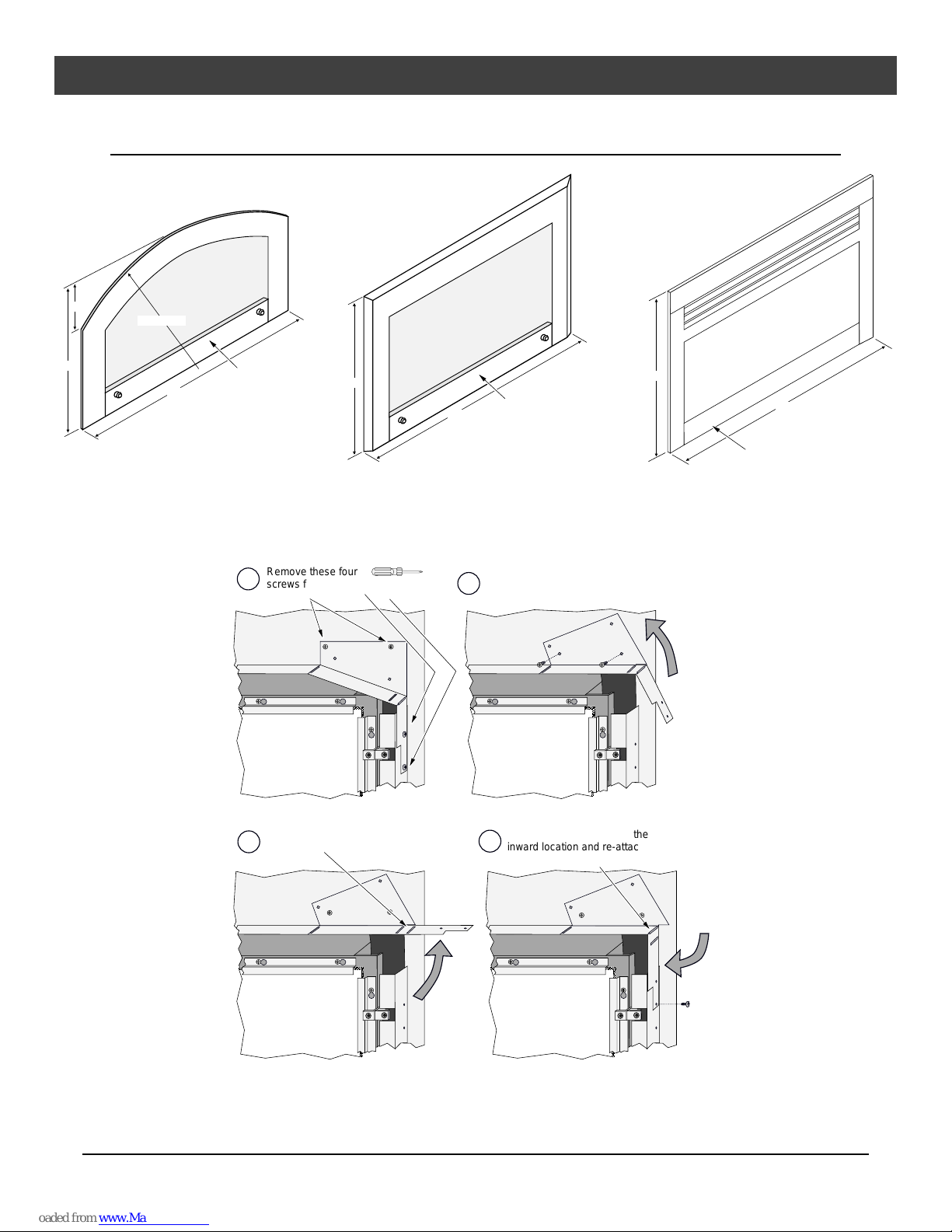
Face Dimensions
Classic Arched
(Gold, Black, or Artisan*)
5"
29"
Radius = 35”
36”
* Artisan faces may vary slightly in size
due to the forging process.
Modifying the Face Angle for Rectangular Faces
If using a rectangular face, adjust the face angles at the top corners of the glass (see the illustration
below).
Access Door
Remove these four
a
screws from the face
angle.
Rectangular Bevel Face
(Black or Gold)
27-1/2”
Phillips
Screwdriver
Access Door
38”
Bend the face angle up and replace
b
the two screws on the upper section.
Architectural Faces
(French Country,
Arts & Crafts,
Art Deco, or Neo-Classical)
29-3/8”
Access Door
36-1/4”
Front of
Fireplace
Glass
Straighten the face angle.
c
Re-bend the face angle at the
d
inward location and re-attach the
lower portion with one screw.
Travis Industries 93508118 270900

Installation (for qualified installers only) 13
Facing and Hearth Examples
Side View
Face
SUGGESTION:
If using a hearth, make your platform height a
dimension that will accommodate the size tiles
you are using and the 1" between the base of
the fireplace and the bottom of the face.
3/8" Thick
1/2" Cement
Board
Wood Sub
Floor
Tile
Fireplace
1"
2x4 and Plywood Platform
Base of Fireplace
Three-Dimensional View
Access Door
NOTE:
When fully installed, there will be a 1/2"
air space below the access door on the
face. Do not block this space (it is
required for access door opening and
air flow).
Note how the tile facing fits behind
the face on the side and top and
butts up to the face on the bottom.
Face
Side of
Fireplace
1/2" Cement Board
& 3/8" Tile
(tucked behind the
face)
Base of Fireplace
2x4 and
Plywood
Platform
Tile
Cement Board
Travis Industries 93508118 270900
14 Installation (for qualified installers only)
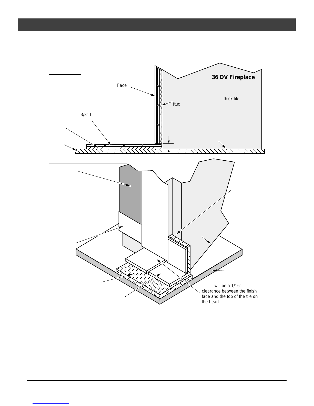
Facing and Hearth Examples (continued)
Side View
36 DV Fireplace
Face
1/2" Cement Board & 3/8" thick tile
(tucked behind the face)
3/8" Thick
1/2" Cement
Board
Wood Sub
Floor
Three-Dimensional View
Face
Tile
1"
Base of Fireplace
NOTE:
When hearth installation is
correctly completed, there will
be a 1/2" air space below the
access door on the face. Do
not block this air space (it is
required for access door
opening and proper air flow).
Access
Door
1/2" Cement
Board
WARNING:
Do not install cement board underneath the fireplace. To do so
would leave a large gap underneath the finish faceplate sides.
3/8" Tile
Side of
Fireplace
Base of
Fireplace
There will be a 1/16"
clearance between the finish
face and the top of the tile on
the hearth.
Note how the
tile facing fits
behind the
face on the
side and top.
Wood Sub Floor
Travis Industries 93508118 270900
Installation (for qualified installers only) 15
Mantel Requirements
• The combustible area above the facing must not protrude more than 3/4" from the facing. If it does, it
is considered a mantel and must meet the mantel requirements listed in this manual.
Combustible Mantels
Non-Combustible
Mantels
Max.
Mantel
Depth is
8”
30" Arch face
28-1/2" Rectangular face
30-3/8” Architectural face
24” Min. Arch Faces
22” Min. Rect. Faces
Combustible Mantel
Non-Combustible mantels must maintain a 12"
clearance to the top of the face and be located
below the header -or- maintain a 24" clearance.
Max.
Mantel
Depth is
8”
Travis Industries 93508118 270900
Min. 12"
Non-Combustible Mantel
Header
46-1/8"
30" Arch face
28-1/2" Rectangular face
30-3/8" Architectural face
16 Installation (for qualified installers only)
Vent Requirements
! The vent must maintain the required clearance to combustible materials to prevent a fire (see
“Clearances” below). Do not fill air spaces with insulation.
! The gas appliance and vent system must be vented directly to the outside of the building, and never
be attached to a chimney serving a separate solid fuel or gas-burning appliance. Each direct vent gas
appliance must use it's own separate vent system.
Altitude Considerations
This heater has been tested at altitudes ranging from sea level to 8,000 feet (2,400 M). In this testing we have
found that the heater, with its standard orifice, burns correctly with just an air shutter adjustment.
! Failure to adjust the air shutter properly may lead to improper combustion which can create a safety hazard.
Consult your dealer or installer if you suspect an improperly adjusted air shutter.
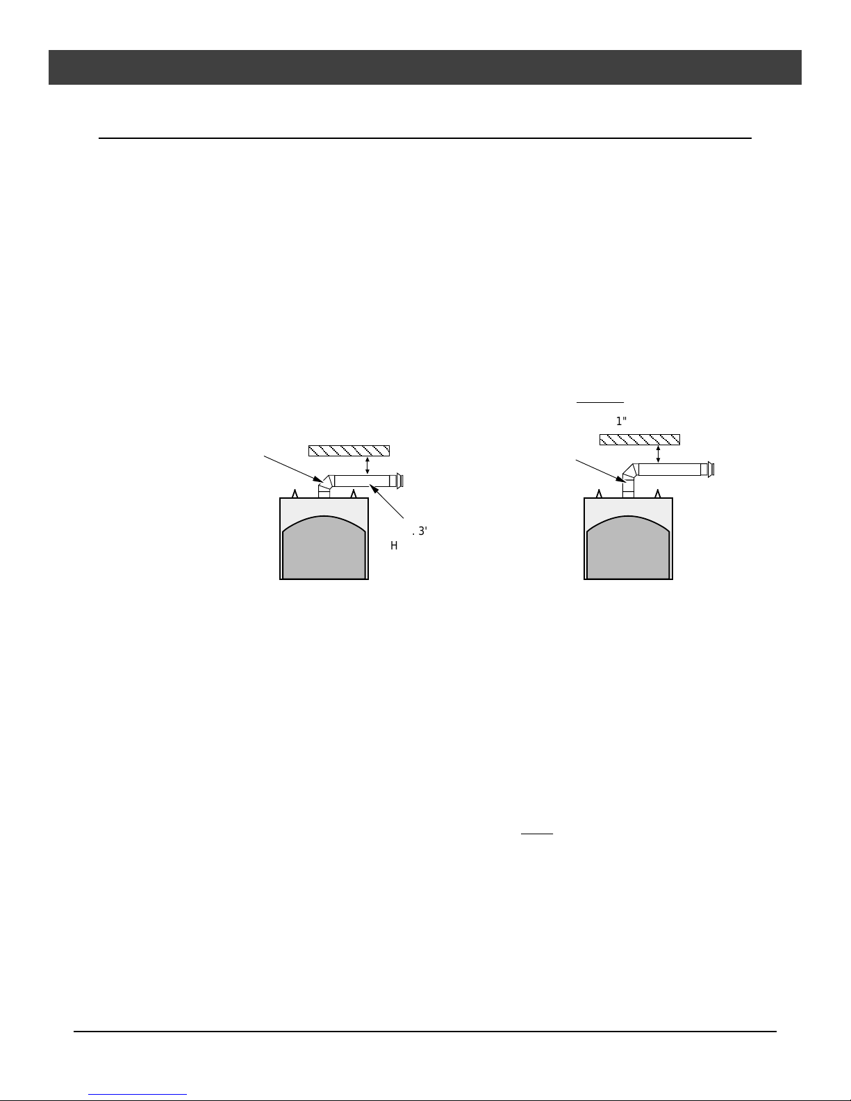
Clearances
Minimum 1” clearance to all combustibles (measured from the outside of the pipe) except for the following:
When using 6-5/8" vent, a
horizontal termination, and
an elbow directly off the
top of the fireplace, a 2"
clearance is required
above the horizontal
sections (1" to the side
and below).
2" Clearance
With any vertical
vent directly off the
fireplace, the
clearance is 1".
Max. 3'
Horizontal
Run
1" Clearance
Use of 8” Diameter Pipe
• Most venting configurations use 6-5/8” diameter vent. To achieve longer horizontal runs (over 12’)
with a horizontal termination, 8” dia. Simpson Duravent type GS Direct Vent may be used. See the
section “Horizontal Terminations using 8” Diameter Vent” for details. Part Numbers are listed below.
Straight Lengths
1208B 6" Pipe Length, Black
1207B 9" Pipe Length, Black
1206B 12" Pipe Length, Black
1204B 24" Pipe Length, Black
1203B 36" Pipe Length, Black
1202B 48" Pipe Length, Black
1211B 11” to 14-5/8" Adjustable Pipe,
Black
Terminations
1284 Horizontal Square Termination
1285 Hor. High Wind Termination
1250 Vinyl Siding Stand-off
Elbows
1245B 45° Elbow, Black
1290B 90° Elbow, Black
Penetration, Support
1242 Wall Firestop
1241 Cathedral Ceiling Support Box
1263 Ceiling Fire-stop
1288 Wall Strap
Adapter (6-5/8” to 8” dia.)
925T DV GS 6-5/8” to 8” Increaser
Part Numbers for 6-5/8” Diameter Vent
• Use Model GS Direct Vent manufactured by Simpson Dura-Vent only . Follow the installation
instructions included with the vent. For the nearest Simpson Dura-Vent supplier, call (800) 835-4429.
Vent part numbers and descriptions are listed below.
Straight Lengths
908B 6" Pipe Length, Black (interior)
907B 9" Pipe Length, Black (interior)
906 12" Pipe Length, Galvanized
906B 12" Pipe Length, Black (interior)
904 24" Pipe Length, Galvanized
904B 24" Pipe Length, Black (interior)
903 36" Pipe Length, Galvanized
903B 36" Pipe Length, Black (interior)
902 48" Pipe Length, Galvanized
902B 48" Pipe Length, Black (interior)
911B 11" to 14 5/8" Adjustable, Black (interior)
Travis Industries 93508118 270900
Vent Terminations
981 Snorkel Termination (36" rise)
(for basement or raised
termination installations)
982 Snorkel Termination (14" rise)
(for basement or raised
termination installations)
984 Horizontal Square Termination
950 Vinyl Siding Stand-off
991 High Wind Vertical
Termination
Elbows
990 90• Elbow
990B 90• Elbow, Black (interior)
Penetration, Support
942 Wall Thimble
941 Cathedral Ceiling Support Box
943 Flashing, 0/12 to 6/12 Roof Pitch
943S Flashing, 7/12 to 12/12 Roof Pitch
953 Storm Collar
963 Ceiling Fire-stop
988 Wall Strap
Installation (for qualified installers only) 17
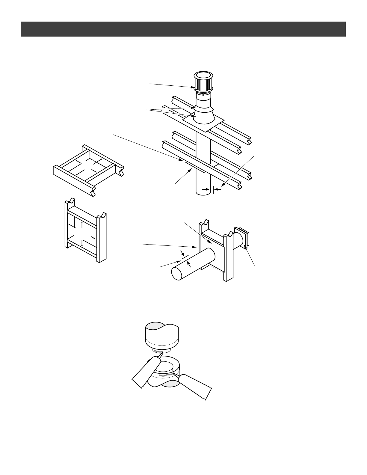
Vent Installation
• In addition to the requirements below, follow the requirements provided with the vent.
Vertical Termination
Use a roof flashing and storm collar
whenever passing through the roof
Use a firestop whenever
passing through a ceiling
8-5/8"
8-5/8"
or
10"
or
10"
Minimum framing
for fire stop
Minimum
Framing for
wall thimble
Use a support box
on exposed vent
Use a firestop whenever
passing through a wall
Vertical Vent
Requirements
Maintain a minimum 1"
clearance from vent to
any combustible
Horizontal Vent
Requirements
Horizontal TerminationMaintain a minimum 1" clearance (2" in
some cases - see "Clearances") from
vent to any combustible
• Apply high-temperature silicone to the inner and outer pipe before assembling the sections (on the
male, upper section). This seals the inner pipe from the outer pipe. Slide the sections together and
turn 1/4 turn until the sections lock in place. Install three metal screws through each joint to lock the
outer section in place (see the instructions included with the vent for further details).
Apply a 1/8" (3 mm)
bead of hightemperature silicone
to the inner and
outer pipe. The
silicone must seal
the inner pipe from
the outer pipe.
Silicone
Silicone
• Horizontal sections require a 1/4" rise every 12" of travel
• Horizontal sections require non-combustible support every three feet (e.g.: plumbing tape)
Travis Industries 93508118 270900
 Loading...