

Page 1

G
PN 50362:C0 ECN 01-155
Control Relay Module
ACM-8RF
Instruction Manual
Document 50362
03/21/2001 Rev:
C
Page 2

Fire Alarm System Limitations
An automatic fire alarm system–typically made up
of smoke detectors, heat detectors, manual pull
stations, audible warning devices, and a fire alarm
control with remote notification capability–can provide
early warning of a developing fire. Such a system,
however, does not assure protection against property
damage or loss of life resulting from a fire.
The Manufacturer recommends that smoke and/or
heat detectors be located throughout a protected
premise following the recommendations of the current
edition of the National Fire Protection Association
Standard 72 (NFPA 72), manufacturer's recommendations, State and local codes, and the recommendations contained in the Guide for Proper Use of System
Smoke Detectors, which is made available at no
charge to all installing dealers. A study by the
Federal Emergency Management Agency (an agency
of the United States government) indicated that
smoke detectors may not go off in as many as 35% of
all fires. While fire alarm systems are designed to
provide early warning against fire, they do not guarantee warning or protection against fire. A fire alarm
system may not provide timely or adequate warning, or
simply may not function, for a variety of reasons:
Smoke detectors may not sense fire where smoke
cannot reach the detectors such as in chimneys, in or
behind walls, on roofs, or on the other side of closed
doors. Smoke detectors also may not sense a fire on
another level or floor of a building. A second-floor
detector, for example, may not sense a first-floor or
basement fire.
Particles of combustion or "smoke" from a developing fire may not reach the sensing chambers of smoke
detectors because:
• Barriers such as closed or partially closed doors,
walls, or chimneys may inhibit particle or smoke
flow.
• Smoke particles may become "cold," stratify, and
not reach the ceiling or upper walls where detectors are located.
• Smoke particles may be blown away from detectors by air outlets.
• Smoke particles may be drawn into air returns
before reaching the detector.
The amount of "smoke" present may be insufficient to
alarm smoke detectors. Smoke detectors are
designed to alarm at various levels of smoke density.
If such density levels are not created by a developing
fire at the location of detectors, the detectors will not
go into alarm.
Smoke detectors, even when working properly, have
sensing limitations. Detectors that have photoelectronic sensing chambers tend to detect smoldering
fires better than flaming fires, which have little visible
smoke.
Detectors that have ionizing-type sensing chambers
tend to detect fast-flaming fires better than smoldering
fires. Because fires develop in different ways and are
often unpredictable in their growth, neither type of
detector is necessarily best and a given type of
detector may not provide adequate warning of a fire.
Smoke detectors cannot be expected to provide
adequate warning of fires caused by arson, children
playing with matches (especially in bedrooms),
smoking in bed, and violent explosions (caused by
escaping gas, improper storage of flammable
materials, etc.).
While a fire alarm system may lower insurance
rates, it is not a substitute for fire insurance!
Heat detectors do not sense particles of combustion
and alarm only when heat on their sensors increases
at a predetermined rate or reaches a predetermined
level. Rate-of-rise heat detectors may be subject to
reduced sensitivity over time. For this reason, the
rate-of-rise feature of each detector should be tested
at least once per year by a qualified fire protection
specialist. Heat detectors are designed to protect
property, not life.
IMPORTANT! Smoke detectors must be installed in
the same room as the control panel and in rooms
used by the system for the connection of alarm
transmission wiring, communications, signaling, and/or
power. If detectors are not so located, a developing
fire may damage the alarm system, crippling its ability
to report a fire.
Audible warning devices such as bells may not alert
people if these devices are located on the other side
of closed or partly open doors or are located on
another floor of a building. Any warning device may
fail to alert people with a disability or those who have
recently consumed drugs, alcohol or medication.
Please note that:
• Strobes can, under certain circumstances, cause
seizures in people with conditions such as
epilepsy.
• Studies have shown that certain people, even
when they hear a fire alarm signal, do not respond
or
comprehend the meaning of the signal. It is the
property owner's responsibility to conduct fire drills
and other training exercise to make people aware
of fire alarm signals and instruct them on the
proper reaction to alarm signals.
• In rare instances, the sounding of a warning device
can cause temporary or permanent hearing loss.
A fire alarm system will not operate without any
electrical power. If AC power fails, the system will
operate from standby batteries only for a specified
time and only if the batteries have been properly
maintained and replaced regularly.
Equipment used in the system may not be
technically compatible with the control. It is essential
to use only equipment listed for service with your
control panel.
Telephone lines needed to transmit alarm signals
from a premise to a central monitoring station may be
out of service or temporarily disabled. For added
protection against telephone line failure, backup radio
transmission systems are recommended.
The most common cause of fire alarm malfunction is
inadequate maintenance. To keep the entire fire
alarm system in excellent working order, ongoing
maintenance is required per the manufacturer's
recommendations, and UL and NFPA standards. At a
minimum, the requirements of Chapter 7 of NFPA 72
shall be followed. Environments with large amounts
of dust, dirt or high air velocity require more frequent
maintenance. A maintenance agreement should be
arranged through the local manufacturer's representative. Maintenance should be scheduled monthly or as
required by National and/or local fire codes and
should be performed by authorized professional fire
alarm installers only. Adequate written records of all
inspections should be kept.
LimWarSm.p65 01/10/2000
Page 3

Installation Precautions
WARNING - Several different sources of power can
be connected to the fire alarm control panel.
Disconnect all sources of power before servicing.
Control unit and associated equipment may be damaged by removing and/or inserting cards, modules, or
interconnecting cables while the unit is energized. Do
not attempt to install, service, or operate this unit until
this manual is read and understood.
CAUTION - System Reacceptance Test after Software Changes. To ensure proper system operation,
this product must be tested in accordance with NFPA
72 Chapter 7 after any programming operation or
change in site-specific software. Reacceptance testing is required after any change, addition or deletion
of system components, or after any modification,
repair or adjustment to system hardware or wiring.
All components, circuits, system operations, or software functions known to be affected by a change must
be 100% tested. In addition, to ensure that other
operations are not inadvertently affected, at least 10%
of initiating devices that are not directly affected by
the change, up to a maximum of 50 devices, must
also be tested and proper system operation verified.
This system meets NFPA requirements for operation
at 0-49° C/32-120° F
85% RH (non-condensing) at 30°
the useful life of the system's standby batteries and
the electronic components may be adversely affected
by extreme temperature ranges and humidity. Therefore, it is recommended that this system and all
peripherals be installed in an environment with a
nominal room temperature of 15-27° C/60-80° F.
Verify that wire sizes are adequate for all initiating
and indicating device loops. Most devices cannot
tolerate more than a 10% I.R. drop from the specified
device voltage.
and at a relative humidity of
C/86° F. However,
Adherence to the following will aid in problem-free
installation with long-term reliability:
Like all solid state electronic devices, this system
may operate erratically or can be damaged when
subjected to lightning-induced transients. Although no
system is completely immune from lightning transients
and interferences, proper grounding will reduce susceptibility. Overhead or outside aerial wiring is not
recommended, due to an increased susceptibility to
nearby lightning strikes. Consult with the Technical
Services Department if any problems are anticipated
or encountered.
Disconnect AC power and batteries prior to
removing or inserting circuit boards. Failure to do so
can damage circuits.
Remove all electronic assemblies prior to any
drilling, filing, reaming, or punching of the enclosure.
When possible, make all cable entries from the sides
or rear. Before making modifications, verify that they
will not interfere with battery, transformer, and printed
circuit board location.
Do not tighten screw terminals more than 9 in-lbs.
Over-tightening may damage threads, resulting in
reduced terminal contact pressure and difficulty with
screw terminal removal.
Though designed to last many years, system components can fail at any time. This system contains
static-sensitive components. Always ground yourself
with a proper wrist strap before handling any circuits
so that static charges are removed from the body.
Use static-suppressive packaging to protect electronic
assemblies removed from the unit.
Follow the instructions in the installation, operating,
and programming manuals. These instructions must
be followed to avoid damage to the control panel and
associated equipment. FACP operation and reliability
depend upon proper installation by authorized
personnel.
FCC Warning
WARNING: This equipment generates, uses, and
can radiate radio frequency energy and if not
installed and used in accordance with the instruction manual, may cause interference to radio
communications. It has been tested and found to
comply with the limits for class A computing device pursuant to Subpart B of Part 15 of FCC
Rules, which is designed to provide reasonable
protection against such interference when operated in a commercial environment. Operation of this
equipment in a residential area is likely to cause
interference, in which case the user will be required to correct the interference at his own
expense.
Canadian Requirements
This digital apparatus does not exceed the Class
A limits for radiation noise emissions from digital
apparatus set out in the Radio Interference
Regulations of the Canadian Department of
Communications.
Le present appareil numerique n'emet pas de
bruits radioelectriques depassant les limites
applicables aux appareils numeriques de la
classe A prescrites dans le Reglement sur le
brouillage radioelectrique edicte par le ministere
des Communications du Canada.
LimWarSm.p65 01/10/2000
Page 4

This page intentionally left blank
4
ACM-8RF PN 50362:C 03/21/01
Page 5

Table of Contents
Table of Contents
1. Introduction
General...................................................................................................7
Mounting ............................................................................................... 7
Features .................................................................................................8
Relays .................................................................................................8
24 VDC Power and Earth Ground......................................................8
EIA-485 Communications..................................................................9
Address Switches ...............................................................................9
Relay Function Selection....................................................................9
Mode Selection...................................................................................9
Related Documentation........................................................................9
2. Installation
Mounting the Enclosure. ....................................................................11
Wiring the Power Terminal Blocks...................................................11
Wiring the Relay Terminal Blocks....................................................12
Wiring the EIA-485 Terminal Blocks...............................................13
Wiring Specifications....................................................................... 13
EIA-485 Shield in Conduit ..........................................................13
EIA-485 Shield Not in Conduit ...................................................14
EIA-485 - TB2 Terminals ................................................................14
Configuring the ACM-8RF................................................................15
Address Switches - SW1 and SW2 ..................................................15
Relay Assignment DIP Switch - SW3..............................................15
Mode Select Switch - SW4 ..............................................................16
Mounting in the ABS-8RF Enclosure ...............................................16
UL Power-limited Wiring Requirements .........................................17
3. Electrical Ratings
24 VDC.................................................................................................19
Relay Contacts ....................................................................................19
Data Communications Port ...............................................................19
Power Requirements ..........................................................................19
Appendix A: MS-5210UD
Capabilities..........................................................................................21
FACP Activations ............................................................................... 22
Alarm Only Activation.....................................................................22
Alarm and Trouble Activation .........................................................23
Application Example #1 .....................................................................24
Application Example #2 .....................................................................25
Application Example #3 .....................................................................26
Application Example #4 .....................................................................28
Page 6

Table of Contents
Appendix B: MS-9200
Capabilities ..........................................................................................31
Testing..................................................................................................31
Wiring ..................................................................................................31
FACP Activations ...............................................................................32
Alarm Only Activation .....................................................................32
Alarm and Trouble Activation..........................................................33
Appendix C: MS-9600
Capabilities ..........................................................................................37
Testing..................................................................................................37
Wiring ..................................................................................................37
Configuration ......................................................................................38
Setting Rotary Switches ...................................................................38
Mode Select ......................................................................................39
Alarm Only or Alarm/Trouble Mode...........................................39
Receive Only or Receive/Transmit Mode....................................39
Setting the DIP Switches ..................................................................40
Alarm Only Activation.................................................................40
Alarm and Trouble Activation .....................................................41
Multiple ACM-8RFs ....................................................................42
Page 7
1. Introduction
General
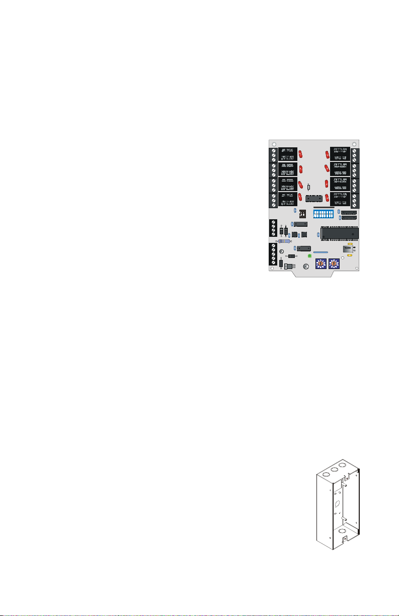
The ACM-8RF Relay Control Module contains eight high current (5 amps)
Form-C relays. The module interfaces to host Fire•Lite control panels which
employ an EIA-485 communications bus and may be connected to the bus up
to 6,000 feet away from the host control panel.
Typically, each relay is assigned to a zone on the
host fire alarm control panel. The relays may be
triggered by either a zone alarm (activation) or
zone trouble. The relays may also take on
special functions depending upon the host
panel. Refer to the Appendices for additional
information.
The ACM-8RF Relay Control Module may be
used in combination with the following
products on the same EIA-485 bus circuit:
• AFM/ACM Series LED annunciators
• LDM Series graphic annunciators
• UDACT-F (Universal Digital Alarm Communicator/Transmitter)
• LED-10 Annunciator
EIA-485 bus compatible accessories are designed to provide maximum
flexibility to system configurations. Examples include multiple remote LED
annunciators with customized labels per corresponding area or function,
multiple remote graphic annunciators that illustrate building layout and floor
plans, remote DACTs for strategic mounting location near telephone
equipment plus remote high current switching relays for such purposes as fan
and damper control, elevator recall and door releasing.
OFF
12345678
O
12
F
F
ACM-8RF.cdr
Mounting
The ACM-8RF module will mount to an ABS-8RF backbox.
A blank faceplate is provided with the backbox.
The CAB-3F Series cabinets, with CHS-4L or CHS-4F
chassis, may also be used to house several ACM-8RFs.
ACM-8RF PN 50362:C 03/21/01
ABS-8RF
abs8rf.cdr
7
Page 8
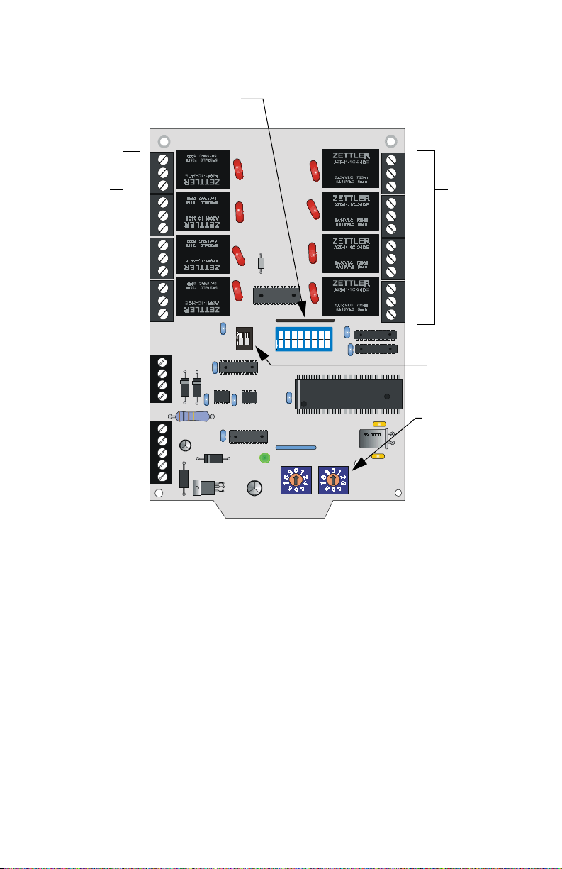
1. Introduction Features
Features
SW3 - Relay Assignment
DIP Switches
Relays
TB2 - EIA-485
Terminal Block
TB1 - 24 VDC
Terminal Block
Relays
K4
K3
K2
K1
OFF
12345678
O
12
F
F
Figure 1 ACM-8RF Features
K5
Relays
K6
K7
K8
ACM-8RF.cdr
SW4 - Mode
Select
Switch
SW1-SW2
Address
Select Rotary
Switches
The Relay Control Module provides eight Form-C relays with 5 amp contacts
@ 125 VAC (resistive) or 30 VDC (resistive) and 2 amps at 125 VAC
inductive). The relay contacts are gold plated silver alloy for medium duty
switching and are not intended for motor control or pilot duty. Wiring to the
relays is via sturdy removable terminal blocks.
24 VDC Power and Earth Ground
Wiring to removable terminal block TB1 is for 24 VDC power-limited,
regulated, nonresettable power from the host FACP or a compatible UL listed
battery backed power supply such as the Fire•Lite FCPS-24F. This terminal
block may be used to daisy chain the 24 VDC to other ACM-8RFs or EIA-485
Fire•Lite compatible devices.
8
ACM-8RF PN 50362:C 03/21/01
Page 9

Related Documentation 1. Introduction
EIA-485 Communications
Wiring to removable terminal block TB2 is for communications over the EIA485 bus. The bus carries commands and data sent between the host FACP and
ACM-8RFs. The EIA-485 circuit is power-limited. The host FACP supervises
devices wired to the EIA-485 bus.
A maximum of 32 ACM-8RFs may be connected to the FACPs EIA-485 bus,
but if other types of devices are also connected to the bus, the maximum
number of ACM-8RFs must be reduced by the total of such devices.
Address Switches
Two rotary BCD (Binary Coded Decimal) switches, located on the lower right
of the module, are used to set the ACM-8RF system address. SW1 represents
the 'tens' position and SW2 represents the 'ones' position of the address setting.
Relay Function Selection
DIP switch SW3 is used to program the assignment of each ACM-8RF relay
to either a zone function (such as zone alarm or zone trouble triggering) or to
a system function (such as system alarm, system trouble, system supervisory,
signal silence, pre-alarm or AC fail). Be certain to review the Appendices for
information on SW3 switch settings for specific FACPs and the operation and
options available to each host FACP.
Mode Selection
DIP switch SW4 is used to set the mode of operation for the ACM-8RF as
follows:
• #1 sets Alarm activation or Alarm/Trouble activation mode.
• #2 sets Receive or Receive/Transmit mode.
Related Documentation
Further details about products referenced in this document can be found in the
manuals for the particular fire alarm control panel and components.
Product
MS-5210UD Fire Alarm Control Panel Instruction Manual 50193
MS-9200 Fire Alarm Control Panel Instruction Manual 51003
MS-9600 Fire Control Panel Instruction Manual 51335
LED-10 Remote Fire Annunciator 50400
FCPS-24F Instruction Manual 50079
UDACT-F Instruction Manual 50049
CAB-3F Series Cabinets 15391
Table 1 Related Documentation
ACM-8RF PN 50362:C 03/21/01
Part
Number
9
Page 10

1. Introduction Related Documentation
NOTES
10
ACM-8RF PN 50362:C 03/21/01
Page 11
2. Installation
Mounting the Enclosure.
Select and remove the appropriate knockout(s) on the ABS-8RF enclosure.
Securely mount the enclosure.
Ground the enclosure to a solid electrical ground per NEC Article 250.
Pull all wiring into the enclosure (refer to "UL Power-limited Wiring
Requirements" on page 17).
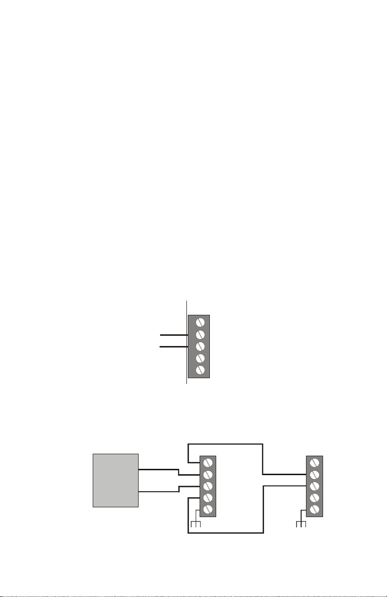
Wiring the Power Terminal Blocks
24 VDC power supplied by the host control panel or external power supply
must be regulated and power-limited. Th is power is inherently supervised (loss
of power also results in a communication failure at the control panel).
• Limit the total wire resistance to 10 ohms.
• Connect 24 VDC power from FACP or Power Supply to TB1-3 (+)
and TB1-4 (–).
• Connect earth ground (TB1-1
backbox or cabinet.
24 VDC
Power
Figure 2 24 VDC Power & Earth Ground Terminals - TB1
Wiring of multiple modules.
Host FACP or Remote
Power Supply
– 24 VDC
+ 24 VDC
Figure 3 Multiple Module Wiring
) to a mounting screw on the
EARTH
TB1
5
SYS COM (–)
4
SYS COM (–)
3
24 V (+)
2
24 V (+)
1
EARTH
ACM8RF-TB1.cdr
First ACM-8RF -- -- -- -- -- -- Last ACM-8RF
TB1
5
4
3
2
1
TB1
5
4
3
2
1
ACM8RF-power.cdr
ACM-8RF PN 50362:C 03/21/01
11
Page 12
2. Installation Wiring the Relay Terminal Blocks
Wiring the Relay Terminal Blocks
The ACM-8RF provides eight relays with Form-C contacts rated for 5 amps.
Note: Wiring from these relays is not supervised.
The terminal assignments are illustrated below. For information on wiring
limitations, refer to "UL Power-limited Wiring Requirements" on page 17.
Relay 4
Normally Open
Common
Normally Closed
Relay 3
Relay 2
Relay 1
OFF
12345678
O
12
F
F
Note: All Relays have the same terminal
assignment position as those on relay #4 & #5
Figure 4 Relay Terminal Assignments
Relay 5
Normally Open
Common
Normally Closed
Relay 6
Relay 7
Relay 8
ACM8RF-relay.cdr
12
ACM-8RF PN 50362:C 03/21/01
Page 13
Wiring the EIA-485 Terminal Blocks 2. Installation
Wiring the EIA-485 Terminal Blocks
Communications between the Fire Alarm Control Panel and the ACM-8RF is
accomplished over a two-wire EIA-485 serial communications bus which must
be power-limited. Communications between the host FACP and ACM-8RFs
is supervised by the fire alarm control panel.
Wiring Specifications
• The EIA-485 circuit cannot be T-tapped; it must be wired in a
continuous fashion from the control panel to the ACM-8RFs.
• The maximum wiring distance between the panel and ACM-8RFs is
6,000 feet.
• The wiring must be a 18 AWG to 14 AWG twisted shielded pair cable
having a characteristic impedance of 120 ohms, +/- 20%.
• Limit the total wire resistance to 100 ohms.
• Do not run cable adjacent to, or in the same conduit as, 120 volts AC
service, noisy electrical circuits that are powering mechanical bells or
horns, audio circuits above 25 V
power circuits.
Note: Never use the EIA-485 shield for grounding purposes. Terminate the EIA-485
shield at the Fire Alarm Control Panel only.
, motor control circuits, or SCR
RMS
Standard Annealed Copper Wire
Wire Size
A.W.G
14 64 4110 0.00323 2.85 2.97 12.4
16 51 2580 0.00203 4.09 4.73 7.82
18 40 1620 0.00128 6.51 7.51 4.92
Diameter
in Mils
Cross Section Ohms per 1000 feet
Circ. Mils Sq. Inch @ 77°F. @ 149°F.
Table 2 Wire Specifications
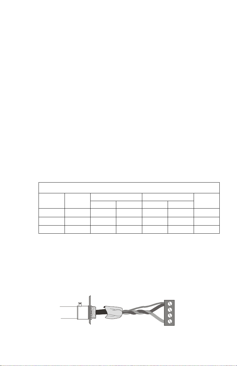
EIA-485 Shield in Conduit
When the EIA-485 wiring is in conduit, connect the shield to system common.
The shield can enter the cabinet, but must be insulated from the cabinet (no
electrical contact). Between ACM-8RFs, wire-nut multiple shields together
(which can be inside of the respective ACM-8RF enclosure but ensure that the
shield does not contact earth ground).
TB2
4
IN (–)
3
OUT (–)
2
OUT (+)
1
IN (+)
Figure 5 Terminating the Shield in Conduit
ACM-8RF PN 50362:C 03/21/01
Pounds per
1000 feet
ACM8RF-term1.cdr
13
Page 14
2. Installation Wiring the EIA-485 Terminal Blocks
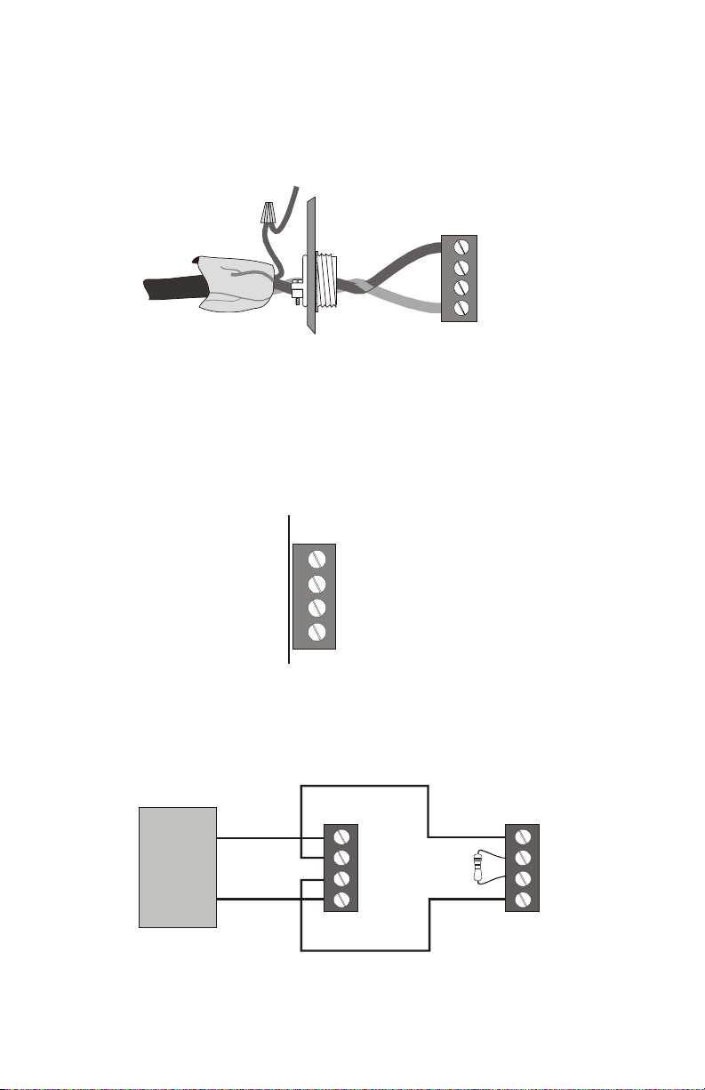
EIA-485 Shield Not in Conduit
When the EIA-485 wiring is not in conduit, terminate the shield at the outside
of the FACP cabinet. Do not allow the shield to enter or even touch the cabinet
housing the ACM-8RFs. Between ACM-8RFs, wire-nut multiple shields
together outside of the respective enclosures. Ensure that the shield does not
touch earth ground at any junction points.
TB2
4
IN (– )
3
OUT (–)
2
OUT (+)
1
IN (+ )
ACM8RF-term2.cdr
Figure 6 Terminating the Shield with No Conduit
EIA-485 - TB2 Terminals
Wire as shown below:
Note: Leave a 120 ohm ELR installed across the EIA-485 Out terminals at the last
ACM-8RF on the circuit (see below). All other ACM-8RFs should not have a resistor
installed.
TB2
4
IN (–)
OUT (–)
3
OUT (+)
2
IN (+)
1
ACM8RF-TB2.cdr
Figure 7 EIA-485 Terminal Block - TB2
Multiple wiring of EIA-485 circuits
Host FACP
EIA-485 (–)
EIA-485 (+)
Figure 8 Wiring Multiple ACM-8RFs - EIA-485
14
First ACM-8RF -- -- -- -- -- -- Last ACM-8RF
TB2
4
3
2
1
TB2
4
3
2
1
ACM-8RF PN 50362:C 03/21/01
ACM8RF-mult.cdr
Page 15

Configuring the ACM-8RF 2. Installation
Configuring the ACM-8RF
Address Switches - SW1 and SW2
It is critical to the operation of the relays that the address switches be set
correctly.
To set the relay module for address ‘01’, position the arrow on SW1 (tens) so
it points to 0 and position the arrow on SW2 (ones) so it points to 1.
TENS
SW1
Figure 9 Address Switches SW1 & SW2
SW2
ONES
ACM8RF-SW1-2.cdr
Relay Assignment DIP Switch - SW3
Check the Appendices for information on SW3 switch settings for specific
FACPs and the operation and options available to each host FACP. The
following illustration provides details on DIP switch placement in the On and
OFF position.
Side View of Switch
Shown in the OFF
Position
OFF
2
1
O
F
F
Figure 10 Relay Assignment Switch
345
678
ACM8RF-S W3.cdr
ACM-8RF PN 50362:C 03/21/01
15
Page 16

2. Installation Mounting in the ABS-8RF Enclosure
Mode Select Switch - SW4
Set the mode of operation as follows:
ALM
ONLY
RCV
ONLY
12
MODE SELECT
Figure 11 Mode Select Switch
• Switch #1 set to the ON position will cause the ACM-8RF relays to
trigger only for FACP zone alarm activation.
• Switch #1 set to the OFF position will cause the ACM-8RF relays to
trigger for FACP zone alarm and zone trouble activation.
• Switch #2 set to the ON position places the ACM-8RF in 'Receive
only' mode. In this mode, the ACM-8RF does not transmit
information back to the host FACP.
ACM8RF-SW4.cdr
• Switch #2 set to the OFF position places the ACM-8RF in 'Receive/
Transmit' mode. In this mode, the ACM-8RF will transmit
supervisory data back to the FACP. The FACP will use this data to
acknowledge that the ACM-8RF is properly communicating.
Note: It is essential that ACM-8RFs and any other devices wired to the EIA-485 bus
and set to the same address not be programmed for receive/transmit mode. Only one
EIA-485 device per address may be set for receive/transmit.
Mounting in the ABS-8RF Enclosure
Place the ACM-8RF in the ABS-8RF backbox. Align the two captive screws
on the top of the relay module and the two mounting holes on the bottom of
the relay module with the standoffs on the backbox.
Note: A solid earth ground connection must be made to one of the top mounting
screws in order to provide transient and lightning protection.
Secure with captive screws at top and with two loose screws at bottom. Plug
all terminal blocks into their respective sockets. Place and secure faceplate to
backbox.
16
ACM-8RF PN 50362:C 03/21/01
Page 17

UL Power-limited Wiring Requirements 2. Installation
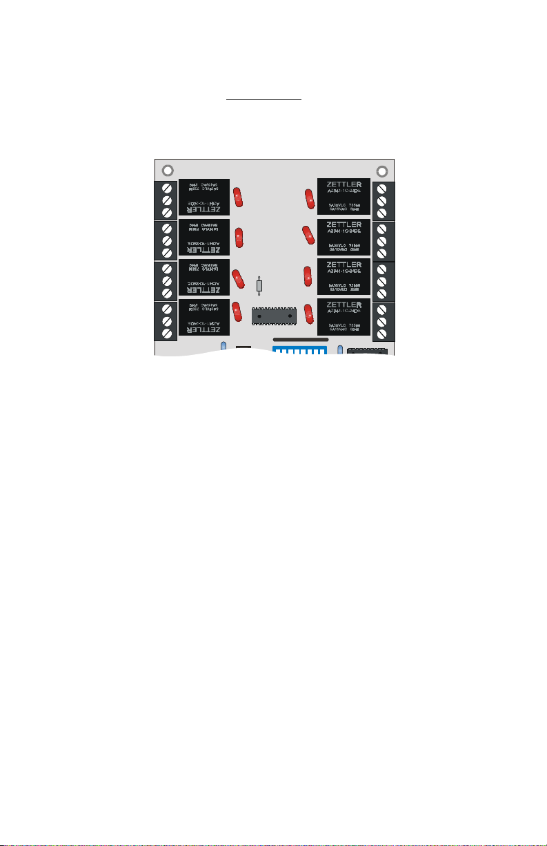
UL Power-limited Wiring Requirements
Power-limited and nonpower-limited circuit wiring must remain separated in
the cabinet. All power-limited circuit wiring must remain at least 0.25" away
from any nonpower-limited circuit wiring. Furthermore, all power-limited
circuit wiring and nonpower-limited circuit wiring must enter and exit the
cabinet through different knockouts and/or conduits. A typical wiring diagram
for the ACM-8RF is shown below. In this diagram, relays K1 through K4 are
being used for power-limited circuits and relays K5 through K8 for nonpowerlimited circuits. Different applications may require different conduit
knockouts to be used. Any conduit knockouts may be used provided that the
nonpower-limited wiring remain separated from the power-limited wiring.
K4
K3
K2
K1
OFF
2345678
1
O
12
F
F
K5
K6
K7
K8
ACM8RF-pwrltd.cdr
Figure 12 Typical Wiring Diagram
Requirements for power-limited and nonpower-limited circuits on the same
ACM-8RF module are as follows:
1. If a mix of power-limited and nonpower- limited circuits are connected
to relays, skip a set of dry contacts to maintain 0.25" spacing between
power-limited and nonpower-limited circuits.
2. If only power-limited or nonpower-limited circuits are being employed,
all relays may be used without skipping any for spacing purposes.
3. Relays K1 through K4 may be used to run all power-limited circuits
while K5 through K8 are being used to run all non-power-limited
circuits.
4. Refer to the Power-limited label located on the FACP door. Make a
notation on the label for each circuit being employed as a Nonpowerlimited circuit. (Refer to the example on the label).
ACM-8RF PN 50362:C 03/21/01
17
Page 18

2. Installation UL Power-limited Wiring Requirements
NOTES
18
ACM-8RF PN 50362:C 03/21/01
Page 19

3. Electrical Ratings
24 VDC
Must be power-limited.
Current Draw from 24 VDC Input @ Normal Standby: 0.030 amps
Maximum current with all output relays activated: 158 mA.
Relay Contacts
UL contact ratings are 5 amps @ 125 VAC (resistive) or 30 VDC (resistive)
and 2 amps @ 125 VAC (inductive).
Data Communications Port
Must be power-limited.
EIA-485 operating at: 20 Kbaud
Power Requirements
Each ACM-8RF relay module must be accounted for in the power calculations
outlined in the respective FACP installation manual. The ACM-8RF draws its
power from the control panel and must be considered when calculating the
primary and secondary power supply requirements for the system. However,
if the current draw dedicated to the ACM-8RF must be calculated as a separate
figure (in cases where a separate UL listed power source is used), use the
equations below:
Standby Current
Number of ACM-8RF modules [ ] X 0.030 = [ ] amps
Alarm Current
1.) Number of ACM-8RF modules [ ] X 0.030 = [ ] amps
2.) Maximum number of relays which
can be activated simultaneously
1. The maximum number of simultaneously activated relays depends on system
configuration and programming.
ACM-8RF PN 50362:C 03/21/01
1
[ ] X 0.016 = [ ] amps
Total Alarm Current (sum of 1 & 2) = [ ] amps
Table 3 Power Requirement Calculations
19
Page 20

3. Electrical Ratings Power Requirements
NOTES
20
ACM-8RF PN 50362:C 03/21/01
Page 21
Appendix A: MS-5210UD
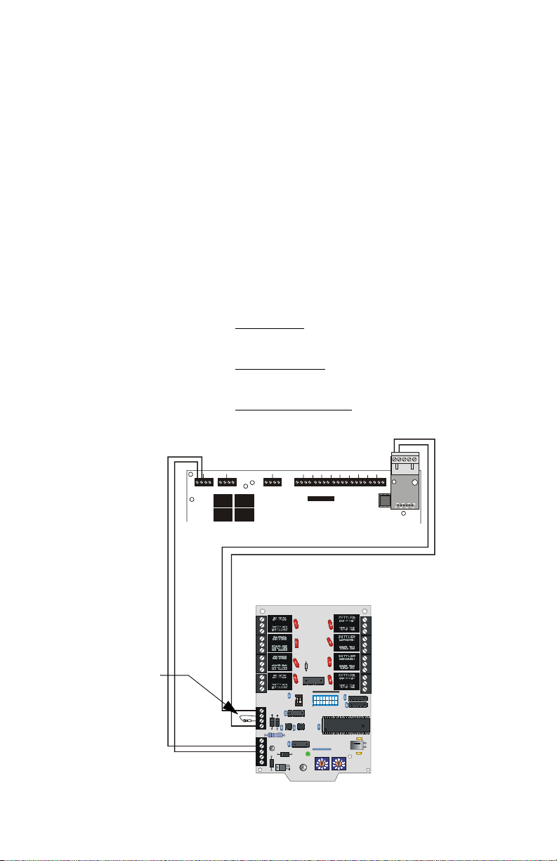
Capabilities
When installed with an MS-5210UD Fire Alarm Control Panel (FACP), the
ACM-8RF Relay Control Modules provide relay activation for each of the ten
FACP zones plus special functions. Options exist to allow for alarm only or
alarm and trouble activations per zone. Output activation for General Alarm,
general trouble, general Supervisory, NAC Fault, AC Fail, System Off Normal,
Walktest start and Battery Trouble are also available. Up to 32 ACM-8RF
Relay Control Modules may be placed onto the EIA-485 communication bus
(if no other devices are installed on the bus).
CAUTION: It is vitally important that, following relay programming, all
relays be tested for correct activation by triggering zones and/or special
functions at the FACP. It should also be noted:
• ACM-8RF Relays will activate
Sequence and for Process Monitoring.
• ACM-8RF Relays will not activate
Retard and Reset periods.
• ACM-8RF Relays will return to normal
autoresettable operation.
Power Out
–
+
TB2 TB3 TB4
120 ohm ELR
Part #71244
TB5
during the Alarm Pre-signal
during the Alarm Verification
if a zone is set for
–
+
+ - + -
J6
J6
12
OFF
12345
O
F
F
678
LED-10IM
J10
EIA-485
Figure 13 Wiring the ACM-8RF to an MS-5210UD
ACM-8RF PN 50362:C 03/21/01
ACM8RF-ms5210ud.cdr
21
Page 22

Appendix A: MS-5210UD FACP Activations
FACP Activations
DIP switch SW3 on the ACM-8RF Relay Control Module is used to determine
which FACP activations will trigger relays on the Relay Control Module.
When installed with an MS-5210UD Fire Alarm Control Panel, use the
following tables to set SW3 switches. Note that two tables are provided; one
table for alarm only operation (SW4-1 = ON) and one table for alarm and
trouble operation (SW4-1 = OFF).
Alarm Only Activation
Table 4 provides the switch settings for ACM-8RF DIP switch SW3 when
configuring the relays to trigger for alarm activation only. Note that a
maximum of three ACM-8RFs are required if one relay is to be designated to
trigger on any FACP alarm. If a general system alarm relay is not required, two
ACM-8RFs may be used to allow individual relay triggering for activation of
FACP zones 1 through 10. When using only two ACM-8RFs, be sure to use
the switch settings for the 2nd and 3rd ACM-8RF in Table 4. Refer to "Relay
Assignment DIP Switch - SW3" on page 15 for information on setting DIP
switch SW3.
MS-5210UD Zone ACM-8RF Relay SW3 Settings
System Alarm Relay 1
Not Used Relay 2 (not used)
Not Used Relay 3 (not used)
Not Used Relay 4 (not used)
Not Used Relay 5 (not used)
Not Used Relay 6 (not used)
Not Used Relay 7 (not used)
Not Used Relay 8 (not used)
Z1 Relay 1
Z2 Relay 2
Z3 Relay 3
Z4 Relay 4
Z5 Relay 5
Z6 Relay 6
Z7 Relay 7
Z8 Relay 8
Z9 Relay 1
Z10 Relay 2
n/a Relay 3 (not used)
n/a Relay 4 (not used)
n/a Relay 5 (not used)
n/a Relay 6 (not used)
n/a Relay 7 (not used)
n/a Relay 8 (not used)
1st ACM-8RF
SW3-1 = ON
SW3-5 = ON
All others = OFF
2nd ACM-8RF
SW3-2 = ON
SW3-5 = ON
All others = OFF
3rd ACM-8RF
SW3-3 = ON
SW3-5 = ON
All others = OFF
22
Table 4 SW3 Settings for Alarm Only
ACM-8RF PN 50362:C 03/21/01
Page 23

FACP Activations Appendix A: MS-5210UD
Alarm and Trouble Activation
Table 5 provides the switch settings for ACM-8RF DIP switch SW3 when
configuring the relays to trigger for alarm and trouble activation. Note that a
maximum of five ACM-8RFs are required if relays are to be designated to
trigger on any FACP status change. If system status relays are not required,
three ACM-8RFs may be used to allow individual relay triggering for alarm
and trouble activation of FACP zones 1 through 10. When using only three
ACM-8RFs, be sure to use the switch settings for the 3rd, 4th and 5th
ACM-8RF in Table 5.
MS-5210UD
Zone
System Status 1=System Alarm 5=System Trouble
System Status Relay 2 (not used) Relay 6 (not used)
System Status Relay 3 (not used) 7=System Off Normal
System Status Relay 4 (not used) 8=System Supervisory
System Status Relay 1 (not used) 5=NAC(s) Fault
System Status Relay 2 (not used) 6=Walktest Start
System Status Relay 3 (not used) 7=Battery Fail
System Status Relay 4 (not used) 8=AC Fail
Z1 Relay 1 Relay 5
Z2 Relay 2 Relay 6
Z3 Relay 3 Relay 7
Z4 Relay 4 Relay 8
Z5 Relay 1 Relay 5
Z6 Relay 2 Relay 6
Z7 Relay 3 Relay 7
Z8 Relay 4 Relay 8
Z9 Relay 1 Relay 5
Z10 Relay 2 Relay 6
n/a Relay 3 (not used) Relay 7 (not used)
n/a Relay 4 (not used) Relay 8 (not used)
ACM-8RF
Alarm Relay
ACM-8RF Trouble
Relay
Table 5 SW3 Settings for Alarm and Trouble
SW3 Settings
1st ACM-8RF
SW3-1 = ON
SW3-5 = ON
All others = OFF
2nd ACM-8RF
SW3-2 = ON
SW3-5 = ON
All others = OFF
3rd ACM-8RF
SW3-3 = ON
SW3-5 = ON
All others = OFF
4th ACM-8RF
SW3-4 = ON
SW3-5 = ON
All others = OFF
5th ACM-8RF
SW3-1 = ON
SW3-6 = ON
All others = OFF
ACM-8RF PN 50362:C 03/21/01
23
Page 24

Appendix A: MS-5210UD Application Example #1
Application Example #1
Zone Alarm Only Activation (no system status relays)
Program the MS-5210UD at Level 3 addresses 02 - 03 for the proper address
setting. The address selected must be the highest or maximum address value
selected on any annunciator or ACM-8RF connected to the EIA-485 port.
(Refer to the Programming Section of the MS-5210UD Instruction Manual).
For this example, only one relay per zone is required and the ACM-8RFs are
the only devices on the EIA-485 bus. Since only ACM-8RFs occupy the bus,
the address setting for them should be switch SW1 = 0 and switch SW2 = 1.
Enter this address into the MS-5210UD Level 3 addresses 02 - 03.
Since each ACM-8RF module contains eight relays, two ACM-8RF modules
are required for 10 zones. Refer to the following chart for switch settings:
MS-5210UD
Zone
Z1 Relay 1
Z2 Relay 2
Z3 Relay 3
Z4 Relay 4
Z5 Relay 5
Z6 Relay 6
Z7 Relay 7
Z8 Relay 8
Z9 Relay 1
Z10 Relay 2
n/a Relay 3
n/a Relay 4
n/a Relay 5
n/a Relay 6
n/a Relay 7
n/a Relay 8
ACM-8RF
Relay
Switch Settings
1st ACM-8RF
SW1=0; SW2=1 (Address ‘01’)
SW3-2 = ON; SW3-5 = ON
All other SW3s = OFF
SW4-1=ON; SW4-2=ON
2nd ACM-8RF
SW1=0, SW2=1 (Address ‘01’)
SW3-3 = ON; SW3-5 = ON
All other SW3s = OFF
SW4-1=ON; SW4-2=OFF
Table 6 Settings for Zone Alarm Activation
24
ACM-8RF PN 50362:C 03/21/01
Page 25

Application Example #2 Appendix A: MS-5210UD
Application Example #2
Zone Alarm and Trouble Activation (no system status relays)
Program the MS-5210UD at Level 3 addresses 02 - 03 for the proper address
setting. The address selected must be the highest or maximum address value
selected on any annunciator or ACM-8RF connected to the EIA-485 port.
(Refer to the Programming Section of the MS-5210UD Instruction Manual).
For this example, two relays per zone are required for alarm and trouble,
therefore, three ACM-8RFs are necessary. In this example, the ACM-8RFs are
the only devices on the EIA-485 bus. Set the ACM-8RF address switches so
that SW1 = 0 and SW2 = 1 on each
into the MS-5210UD Level 3 addresses 02 - 03. Refer to the following chart
for switch settings:
of the three ACM-8RFs. Enter this address
MS-5210UD
Zone
Z1 Relay 1 Relay 5 1st ACM-8RF
Z2 Relay 2 Relay 6
Z3 Relay 3 Relay 7
Z4 Relay 4 Relay 8
Z5 Relay 1 Relay 5 2nd ACM-8RF
Z6 Relay 2 Relay 6
Z7 Relay 3 Relay 7
Z8 Relay 4 Relay 8
Z9 Relay 1 Relay 5 3rd ACM-8RF
Z10 Relay 2 Relay 6
n/a Relay 3 Relay 7
n/a Relay 4 Relay 8
ACM-8RF
Alarm Relay
ACM-8RF
Trouble Relay
Switch Settings
SW1=0; SW2=1 (Address ‘01’)
SW3-3 = ON; SW3-5 = ON
All other SW3s = OFF
SW4-1=OFF; SW4-2=ON
SW1=0; SW2=1 (Address ‘01’)
SW3-4 = ON; SW3-5 = ON
All other SW3s = OFF
SW4-1=OFF; SW4-2=ON
SW1=0; SW2=1 (Address ‘01’)
SW3-1 = ON; SW3-6 = ON
All other SW3s = OFF
SW4-1=OFF; SW4-2=OFF
Table 7 Settings for Zone Alarm and Trouble Activation
ACM-8RF PN 50362:C 03/21/01
25
Page 26

Appendix A: MS-5210UD Application Example #3
Application Example #3
Two LED-10 Annunciators and 10 Alarm Only Relays
(no system status relays)
Program the MS-5210UD at Level 3 addresses 02 - 03 for the proper address
setting. The address selected must be the highest or maximum address value
selected on any annunciator or ACM-8RF connected to the EIA-485 port.
(Refer to the Programming Section of the MS-5210UD Instruction Manual).
For this example, only one relay per MS-5210UD zone is required and the
ACM-8RFs are sharing the EIA-485 bus with two LED-10s. Since ACM-8RFs
are sharing the bus with two other devices, the address setting for the ACM8RFs should be switches SW1 = 0 and SW2 = 3. Enter this address into the
MS-5210UD Level 3 addresses 02 - 03.
Since each ACM-8RF module contains eight relays, two ACM-8RF modules
are required for 10 zones. Refer to the following chart for switch settings:
MS-5210UD
Zone
Z1 Relay 1
Z2 Relay 2
Z3 Relay 3
Z4 Relay 4
Z5 Relay 5
Z6 Relay 6
Z7 Relay 7
Z8 Relay 8
Z9 Relay 1
Z10 Relay 2
n/a Relay 3
n/a Relay 4
n/a Relay 5
n/a Relay 6
n/a Relay 7
n/a Relay 8
ACM-8RF
Relay
Switch Settings
1st ACM-8RF
SW1=0; SW2=3 (Address ‘03’)
SW3-2 = ON; SW3-5 = ON
All other SW3s = OFF
SW4-1=ON; SW4-2=ON
2nd ACM-8RF
SW1=0, SW2=3 (Address ‘03’)
SW3-3 = ON; SW3-5 = ON
All other SW3s = OFF
SW4-1=ON; SW4-2=OFF
Table 8 Settings for Zone Alarm Activation with LED-10s
26
ACM-8RF PN 50362:C 03/21/01
Page 27

Application Example #3 Appendix A: MS-5210UD
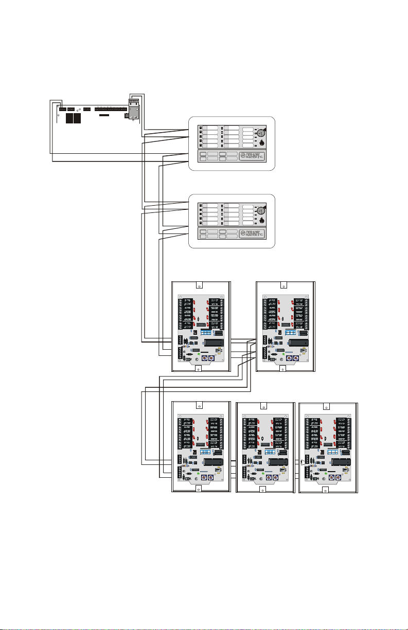
The figure below is provided as an application example of using two LED-10s
and two ACM-8RFs. It is not intended to be used as a wiring diagram.
Refer to Figure 13 on page 21, or the appropriate instruction manuals, for
detailed wiring information.
-
+
LED-10IM
MS-5210UD
FACP Program Level 3
Address 02 = ‘0’
Address 03 = ‘3’
+
-
+ - + -
J6
J6
LED-10 Address ‘01’
FIRE ANNUNCIATOR
Receive/Transmit
LED-10 Address ‘02’
FIRE ANNUNCIATOR
acmfapp3.cdr
Receive/Transmit
ACM-8RF
Address ‘03’
OFF
12345678
O
12
F
F
ACM-8RF
Address ‘03’
OFF
12345678
O
12
F
F
ACM-8RF PN 50362:C 03/21/01
Receive Only
Figure 14 Two LED-10s and Two ACM-8RFs
Receive/Transmit
27
Page 28

Appendix A: MS-5210UD Application Example #4
Application Example #4
Two LED-10 Annunciators, 10 Alarm Only Relays and 20
Alarm/Trouble Relays (no system status relays)
Program the MS-5210UD at Level 3 addresses 02 - 03 for the proper address
setting. The address selected must be the highest or maximum address value
selected on any annunciator or ACM-8RF connected to the EIA-485 port.
(Refer to the Programming Section of the MS-5210UD Instruction Manual).
For this example, only one relay per MS-5210UD zone is required for the first
set of Alarm Only Relays, two relays per MS-5210UD zone is required for the
second set of Alarm and Trouble Relays and the ACM-8RFs are sharing the
EIA-485 bus with two LED-10s. Since ACM-8RFs are sharing the bus with
two other devices, the address setting for the first set of ACM-8RFs should be
switches SW1 = 0 and SW2 = 3 for address '03'. The address setting for the
second set of ACM-8RFs should be switches SW1 = 0 and SW2 = 4 for address
'04'. Enter this highest address into the MS-5210UD Level 3 addresses 02 - 03.
Continued on the next page...
28
ACM-8RF PN 50362:C 03/21/01
Page 29

Application Example #4 Appendix A: MS-5210UD
Since each ACM-8RF module contains eight relays, two ACM-8RF modules
are required for 10 zones of Alarm Only Relays and three ACM-8RF modules
are required for 10 zones of Alarm and Trouble Relays (20 relays required).
MS-5210UD
Zone
Z1 Relay 1
Z2 Relay 2
Z3 Relay 3
Z4 Relay 4
Z5 Relay 5
Z6 Relay 6
Z7 Relay 7
Z8 Relay 8
Z9 Relay 1
Z10 Relay 2
n/a Relay 3
n/a Relay 4
n/a Relay 5
n/a Relay 6
n/a Relay 7
n/a Relay 8
Z1 Relay 1 Relay 5 3rd ACM-8RF
Z2 Relay 2 Relay 6
Z3 Relay 3 Relay 7
Z4 Relay 4 Relay 8
Z5 Relay 1 Relay 5 4th ACM-8RF
Z6 Relay 2 Relay 6
Z7 Relay 3 Relay 7
Z8 Relay 4 Relay 8
Z9 Relay 1 Relay 5 5th ACM-8RF
Z10 Relay 2 Relay 6
n/a Relay 3 Relay 7
n/a Relay 4 Relay 8
ACM-8RF
Alarm Relay
ACM-8RF
Trouble Relay
Switch Settings
1st ACM-8RF
SW1=0; SW2=3 (Address ‘03’)
SW3-2 = ON; SW3-5 = ON
All other SW3s = OFF
SW4-1=ON; SW4-2=ON
2nd ACM-8RF
SW1=0; SW2=3 (Address ‘03’)
SW3-3 = ON; SW3-5 = ON
All other SW3s = OFF
SW4-1=ON; SW4-2=OFF
SW1=0; SW2=4 (Address ‘04’)
SW3-3 = ON; SW3-5 = ON
All other SW3s = OFF
SW4-1=OFF; SW4-2=ON
SW1=0; SW2=4 (Address ‘04’)
SW3-4 = ON; SW3-5 = ON
All other SW3s = OFF
SW4-1=OFF; SW4-2=ON
SW1=0; SW2=4 (Address ‘04’)
SW3-1 = ON; SW3-6 = ON
All other SW3s = OFF
SW4-1=OFF; SW4-2=OFF
Table 9 Settings for Zone Alarm and Trouble Activation with LED-10s
ACM-8RF PN 50362:C 03/21/01
29
Page 30
Appendix A: MS-5210UD Application Example #4
The figure below is provided as an application example of using two LED-10s
and two ACM-8RFs. It is not intended to be used as a wiring diagram.
Refer to Figure 13 on page 21, or the appropriate instruction manuals, for
detailed wiring information.
-
+
LED-10IM
+
-
+ - + -
J6
J6
LED-1 Address ‘01’
FACP Program Level 3
Address 02 = ‘0’
Address 03 = ‘3’
Receive Only
FIRE ANNUNCIATOR
Receive/Transmit
LED-1 Address ‘02’
FIRE ANNUNCIATOR
Receive/Transmit
ACM-8RFs set to Address ‘03’ (Alarm Only)
OFF
12345678
O
12
F
F
OFF
12345678
O
12
F
F
Receive/Transmit
ACM-8RFs set to Address ‘04’ (Alarm and Trouble)
OFF
123456 78
O
12
F
F
OFF
123456 78
O
12
F
F
OFF
12345678
O
12
F
F
acmfapp4.cdr
30
Receive Only
Receive Only
Figure 15 Two LED-10s and Five ACM-8RFs
ACM-8RF PN 50362:C 03/21/01
Receive/Transmit
Page 31

Appendix B: MS-9200
Capabilities
When installed with an MS-9200 Fire Alarm Control Panel (FACP), the ACM8RF Relay Control Modules provide relay activation (alarm only or alarm/
trouble) for each of the 56 FACP zones. Output activation for System Alarm,
System Trouble, Alarm Silence, Walktest, Supervisory, NAC Fault, Battery
Trouble and AC Fail are also available. Up to 32 ACM-8RF Relay Control
Modules may be placed onto the EIA-485 communication bus (if no other
devices are installed on the bus).
Testing
It is vitally important that, following relay programming, all relays be tested
for correct activation by triggering zones and/or special functions at the FACP.
It should also be noted:
• ACM-8RF relays will activate
during the Alarm Pre-signal Sequence.
• ACM-8RF relays will not activate
during the Alarm Verification
Retard and Reset periods.
Wiring
Wire the AMC-8RF to the MS-9200 control panel as shown below.
ACM-8RF
120 ohm ELR
Part #71244
Nonresettable
24 VDC
Power Out
TB4(+) & (–)
24V UNREG 24V NONRS 24V RST
+ - + - + -
T
B
4
BELL 2 PO WER
BELL 1 PO WER
B+ A+ A- B- B+ A+ A- B-
T
B
2
MS-9200 Terminal Blocks
12
SUPV ALAR M TROU BLE
NO C NO NC C NO NC C
T
B
1
OFF
45678
123
O
F
F
EIA-485
TB5 (+) & (–)
T
B
3
PC/PRIN TER
TERM COMM
OUT+ IN+ OUT- IN-
T
B
7
1 COMM 2
T
B
5
ACS
SHIELD
SLC SL C
A B B+ A+ B- A-
T
B
6
ACM8RF-ms9200.cdr
ACM-8RF PN 50362:C 03/21/01
Figure 16 Wiring ACM-8RF to MS-9200
31
Page 32

Appendix B: MS-9200 FACP Activations
FACP Activations
DIP switch SW3 on the ACM-8RF Relay Control Module is used to determine
which FACP activations will trigger relays on the ACM-8RF. Use the following
tables to set SW3 switches. The Address Select Rotary Switches on all ACM8RFs must be set to address ‘01’ (SW1 = 0, SW2 = 1).
Two tables are provided, one table for alarm only operation (SW4-1 = ON) and
one table for alarm and trouble operation (SW4-1 = OFF).
Alarm Only Activation
Table 10 provides the switch settings for ACM-8RF DIP switch SW3 when
configuring the relays to trigger for MS-9200 alarm activation only. A
maximum of eight ACM-8RFs are required if one relay is to be designated to
trigger on any FAC P zone alarm. If a general system alarm relay is not required,
seven ACM-8RFs may be used to allow individual relay triggering for alarm
activation o f FACP z ones 1 through 56. When using seven ACM-8RFs, be sure
to use the switch settings for the 2nd through the eighth ACM-8RF in Table 10.
MS-9200 Zone
System Alarm Relay 1
Not Used Relay 2 Z26 Relay 2
Not Used Relay 3 Z27 Relay 3
Not Used Relay 4 Z28 Relay 4
Not Used Relay 5 Z29 Relay 5
Not Used Relay 6 Z30 Relay 6
Not Used Relay 7 Z31 Relay 7
Not Used Relay 8 Z32 Relay 8
Z1 Relay 1
Z2 Relay 2 Z34 Relay 2
Z3 Relay 3 Z35 Relay 3
Z4 Relay 4 Z36 Relay 4
Z5 Relay 5 Z37 Relay 5
Z6 Relay 6 Z38 Relay 6
Z7 Relay 7 Z39 Relay 7
Z8 Relay 8 Z40 Relay 8
Z9 Relay 1
Z10 Relay 2 Z42 Relay 2
Z11 Relay 3 Z43 Relay 3
Z12 Relay 4 Z44 Relay 4
Z13 Relay 5 Z45 Relay 5
Z14 Relay 6 Z46 Relay 6
Z15 Relay 7 Z47 Relay 7
Z16 Relay 8 Z48 Relay 8
Z17 Relay 1
Z18 Relay 2 Z50 Relay 2
Z19 Relay 3 Z51 Relay 3
Z20 Relay 4 Z52 Relay 4
Z21 Relay 5 Z53 Relay 5
Z22 Relay 6 Z54 Relay 6
Z23 Relay 7 Z55 Relay 7
Z24 Relay 8 Z56 Relay 8
ACM-8RF
Relay
ACM-8RF
SW3 Settings
1st ACM-8RF
SW3-1 = ON
SW3-5 = ON
All others =
OFF
2nd ACM-8RF
SW3-2 = ON
SW3-5 = ON
All others =
OFF
3rd ACM-8RF
SW3-3 = ON
SW3-5 = ON
All others =
OFF
4th ACM-8RF
SW3-4 = ON
SW3-5 = ON
All others =
OFF
MS-9200
Zone
Z25 Relay 1
Z33 Relay 1
Z41 Relay 1
Z49 Relay 1
ACM-8RF
Relay
Table 10 SW3 Settings for Alarm Only
SW3 Settings
5th ACM-8RF
SW3-1 = ON
SW3-6 = ON
All others =
OFF
6th ACM-8RF
SW3-2 = ON
SW3-6 = ON
All others =
OFF
7th ACM-8RF
SW3-3 = ON
SW3-6 = ON
All others =
OFF
8th ACM-8RF
SW3-4 = ON
SW3-6 = ON
All others =
OFF
32
ACM-8RF PN 50362:C 03/21/01
Page 33

FACP Activations Appendix B: MS-9200
Alarm and Trouble Activation
Table 11 provides the switch settings for ACM-8RF DIP switch SW3 when
configuring the relays to trigger for MS-9200 alarm and trouble activation. A
maximum of 16 ACM-8RFs are required if relays are to be designated to trigger
on any FACP status change. If system status relays are not required, 14 ACM8RFs may be used to allow individual relay triggering for alarm and trouble
activation of FACP zones 1 through 56. When using 14 ACM-8RFs, be sure
to use the switch settings for the 3rd through the 16th ACM-8RF in Table 11.
When the MS-9200 is programmed for an annunciator without a UDACT-F,
the first 16 relays will be assigned to the status functions listed in the table
below.
If the MS-9200 is programmed for an annunciator and
16 relays will be assigned to the status functions listed in Table 12 on page 35.
a UDACT-F, the first
MS-9200
Zone
System Status 1=System Alarm 5=System Trouble
System Status Relay 2 (not used) 6=Alarm Silence
System Status Relay 3 (not used) Relay 7 (not used)
System Status Relay 4 (not used) Relay 8 (not used)
System Status Relay 1 (not used) 5= Supervisory
System Status Relay 2 (not used) Relay 6 (not used)
System Status Relay 3 (not used) Relay 7 (not used)
System Status Relay 4 (not used) 8= Panel Trouble
Z1 Relay 1 Relay 5
Z2 Relay 2 Relay 6
Z3 Relay 3 Relay 7
Z4 Relay 4 Relay 8
Z5 Relay 1 Relay 5
Z6 Relay 2 Relay 6
Z7 Relay 3 Relay 7
Z8 Relay 4 Relay 8
Z9 Relay 1 Relay 5
Z10 Relay 2 Relay 6
Z11 Relay 3 Relay 7
Z12 Relay 4 Relay 8
Z13 Relay 1 Relay 5
Z14 Relay 2 Relay 6
Z15 Relay 3 Relay 7
Z16 Relay 4 Relay 8
Z17 Relay 1 Relay 5
Z18 Relay 2 Relay 6
Z19 Relay 3 Relay 7
Z20 Relay 4 Relay 8
ACM-8RF
Alarm
ACM-8RF
Trouble
Table 11 SW3 Settings for Alarm and Trouble
Switch Settings
1st ACM-8RF
SW3-1 = ON;
SW3-5 = ON
All other SW3s = OFF
2nd ACM-8RF
SW3-2 = ON;
SW3-5 = ON
All other SW3s = OFF
3rd ACM-8RF
SW3-3 = ON;
SW3-5 = ON
All other SW3s = OFF
4th ACM-8RF
SW3-4 = ON;
SW3-5 = ON
All other SW3s = OFF
5th ACM-8RF
SW3-1 = ON;
SW3-6 = ON
All other SW3s = OFF
6th ACM-8RF
SW3-2 = ON;
SW3-6 = ON
All other SW3s = OFF
7th ACM-8RF
SW3-3 = ON;
SW3-6 = ON
All other SW3s = OFF
ACM-8RF PN 50362:C 03/21/01
33
Page 34

Appendix B: MS-9200 FACP Activations
MS-9200
Zone
Z21 Relay 1 Relay 5
Z22 Relay 2 Relay 6
Z23 Relay 3 Relay 7
Z24 Relay 4 Relay 8
Z25 Relay 1 Relay 5
Z26 Relay 2 Relay 6
Z27 Relay 3 Relay 7
Z28 Relay 4 Relay 8
Z29 Relay 1 Relay 5
Z30 Relay 2 Relay 6
Z31 Relay 3 Relay 7
Z32 Relay 4 Relay 8
Z33 Relay 1 Relay 5
Z34 Relay 2 Relay 6
Z35 Relay 3 Relay 7
Z36 Relay 4 Relay 8
Z37 Relay 1 Relay 5
Z38 Relay 2 Relay 6
Z39 Relay 3 Relay 7
Z40 Relay 4 Relay 8
Z41 Relay 1 Relay 5
Z42 Relay 2 Relay 6
Z43 Relay 3 Relay 7
Z44 Relay 4 Relay 8
Z45 Relay 1 Relay 5
Z46 Relay 2 Relay 6
Z47 Relay 3 Relay 7
Z48 Relay 4 Relay 8
Z49 Relay 1 Relay 5
Z50 Relay 2 Relay 6
Z51 Relay 3 Relay 7
Z52 Relay 4 Relay 8
Z53 Relay 1 Relay 5
Z54 Relay 2 Relay 6
Z55 Relay 3 Relay 7
Z56 Relay 4 Relay 8
ACM-8RF
Alarm
ACM-8RF
Trouble
Table 11 SW3 Settings for Alarm and Trouble
Switch Settings
8th ACM-8RF
SW3-4 = ON;
SW3-6 = ON
All other SW3s = OFF
9th ACM-8RF
SW3-1 = ON;
SW3-7 = ON
All other SW3s = OFF
10th ACM-8RF
SW3-2 = ON;
SW3-7 = ON
All other SW3s = OFF
11th ACM-8RF
SW3-3 = ON;
SW3-7 = ON
All other SW3s = OFF
12th ACM-8RF
SW3-4 = ON;
SW3-7 = ON
All other SW3s = OFF
13th ACM-8RF
SW3-1 = ON;
SW3-8 = ON
All other SW3s = OFF
14th ACM-8RF
SW3-2 = ON;
SW3-8 = ON
All other SW3s = OFF
15th ACM-8RF
SW3-3 = ON;
SW3-8 = ON
All other SW3s = OFF
16th ACM-8RF
SW3-4 = ON;
SW3-8 = ON
All other SW3s = OFF
34
ACM-8RF PN 50362:C 03/21/01
Page 35

FACP Activations Appendix B: MS-9200
Status functions of first 16 relays if the FACP has a UDACT-F installed.
MS-9200 Zone
System Status 1 System Alarm 5= System Trouble
System Status Relay 2 (not used) 6=Alarm Silence
System Status Relay 3 (not used) 7=Walk Test
System Status Relay 4 (not used) 8=Supervisory
System Status Relay 1 (not used) 5=NAC Fail
System Status Relay 2 (not used) Relay 6 (not used)
System Status Relay 3 (not used) 7=Battery Trouble
System Status Relay 4 (not used) 8=AC Fail
ACM-8RF
Alarm Relay
ACM-8RF Trouble
Relay
Table 12 Status Relays (with UDACT-F)
SW3 Settings
1st ACM-8RF
SW3-1 = ON
SW3-5 = ON
All others = OFF
2nd ACM-8RF
SW3-2 = ON
SW3-5 = ON
All others = OFF
ACM-8RF PN 50362:C 03/21/01
35
Page 36

Appendix B: MS-9200 FACP Activations
NOTES
36
ACM-8RF PN 50362:C 03/21/01
Page 37

Appendix C: MS-9600
Capabilities
When installed with an MS-9600 Fire Alarm Control Panel (FACP), the ACM8RF Relay Control Modules provide relay activation (alarm only or alarm/
trouble) for: each of the 99 FACP zones; the two NACs; each of the 159
modules and 159 detectors on both SLC loops. Output activation for System
Alarm, System Trouble, Alarm Silence, Walktest, Supervisory, NAC Fault,
Battery Trouble and AC Fail are also available. Up to 32 ACM-8RF Relay
Control Modules may be placed onto the EIA-485 communication bus (if no
other devices are installed on the bus).
Testing
It is vitally important that, following relay programming, all relays be tested
for correct activations by triggering zones, points and special functions at the
FACP. It should also be noted:
• ACM-8RF relays will activate
during the Alarm Pre-signal Sequence.
• ACM-8RF relays will not activate
during the Alarm Verification
Retard and Reset periods
Wiring
Wire the ACM-8RF to the MS-9600 control panel as shown below.
ACM-8RF
120 ohm ELR
Part #17244
Nonresettable
24 VDC
Power Out
TB3(+) & (–)
TB3
ACM-8RF PN 50362:C 03/21/01
TB5
TB4
MS-9600 Terminal Blocks
Figure 17 Wiring ACM-8RF to MS-9600
12
OFF
234567 8
1
O
F
F
EIA-485
TB6 (+) & (–)
TB6 TB7
TB8
ACM8RF-ms9600.cdr
37
Page 38

Appendix C: MS-9600 Configuration
Configuration
Setting Rotary Switches
The Address Select Rotary Switches (SW1 & SW2) are used to determine
which FACP annunciator address will trigger relays on the ACM-8RF. Use the
following table to set these switches. Refer to "Address Switches - SW1 and
SW2" on page 15 for information on setting these switches.
M = Module D = Detector
FACP
Address
13 - 19 Not Used
SW1 SW2 Relay Activation for:
1 0 1 8 System Points & Zones 1-56
2 0 2 Zones 57-99 & 2 NACs
3 0 3 Loop 1, Address M1 - M64
4 0 4 Loop 2, Address M1 - M64
5 0 5 Loop 1, Address M65 - M128
6 0 6 Loop 2, Address M65 - M128
707
8 0 8 Loop 1, Address D1 - D64
9 0 9 Loop 2, Address D1 - D64
10 1 0 Loop 1, Address D65 - D128
11 1 1 Loop 2, Address D65 - D128
12 1 2
20 2 0 8 System Points & Zones 1-56
21 2 1 Zones 57-99 & 2 NACs
22 2 2 Loop 1, Address M1 - M64
23 2 3 Loop 2, Address M1 - M64
24 2 4 Loop 1, Address M65 - M128
25 2 5 Loop 2, Address M65 - M128
26 2 6
27 2 7 Loop 1, Address D1 - D64
28 2 8 Loop 2, Address D1 - D64
29 2 9 Loop 1, Address D65 - D128
30 3 0 Loop 2, Address D65 - D128
31 3 1
Loop 1, Address M129 - M159 &
Loop 2, Address M129 - M159
Loop 1, Address D129 - D159 &
Loop 2, Address D129 - D159
Loop 1, Address M129 - M159 &
Loop 2, Address M129 - M159
Loop 1, Address D129 - D159 &
Loop 2, Address D129 - D159
Table 13 SW1 & SW2 Switch Settings
Note: If a UDACT-F is installed and selected in control panel programming, it will
automatically assign addresses 20 - 31 to the UDACT-F and disable the selection of
these addresses.
38
ACM-8RF PN 50362:C 03/21/01
Page 39

Configuration Appendix C: MS-9600
Mode Select
Alarm Only or Alarm/Trouble Mode
Determine if “alarm only” mode or “alarm/trouble” mode is to be used and set
the Mode Select switch SW4-1 as described in "Mode Select Switch - SW4"
on page 16 and below.
If “alarm only” is selected, relays 1 to 8 will activate when an alarm signal is
received from a zone or point.
Zone or Point
1, 9, 17 etc. or 65, 73, 81 etc. Relay 1
2, 10, 18 etc. or 66, 74, 82 etc. Relay 2
3, 11, 19 etc. or 67, 75, 83 etc. Relay 3
4, 12, 20 etc. or 68, 76, 84 etc. Relay 4
5, 13, 21 etc. or 69, 77, 85 etc. Relay 5
6, 14, 22 etc. or 70, 78, 86 etc. Relay 6
7, 15, 23 etc. or 71, 79, 87 etc. Relay 7
8, 16, 24 etc. or 72, 80, 88 etc. Relay 8
Alarm
Signal
Table 14 Alarm Only Setup
If “alarm/trouble” is selected, then relays 1 to 4 will activate when an alarm
signal is received from a zone or point and relays 5 to 8 will activate when a
trouble signal is received from a zone or point.
Zone or Point
1, 9, 17 etc. or 65, 73, 81 etc. Relay 1 5, 13, 21 etc. or 69, 77, 85 etc. Relay 5
2, 10, 18 etc. or 66, 74, 82 etc. Relay 2 6, 14, 22 etc. or 70, 78, 86 etc. Relay 6
3, 11, 19 etc. or 67, 75, 83 etc. Relay 3 7, 15, 23 etc. or 71, 79, 87 etc. Relay 7
4, 12, 20 etc. or 68, 76, 84 etc. Relay 4 8, 16, 24 etc. or 72, 80, 88 etc. Relay 8
Alarm
Signal
Zone or Point
Table 15 Alarm and Trouble Setup
Trouble
Signal
Receive Only or Receive/Transmit Mode
Determine if “receive only” mode or “receive/transmit” mode is to be used and
set the Mode Select switch SW4-2 as described in "Mode Select Switch - SW4"
on page 16.
Note: Only one EIA-485 device per address may be set for receive/transmit.
ACM-8RF PN 50362:C 03/21/01
39
Page 40

Appendix C: MS-9600 Configuration
Setting the DIP Switches
The DIP switch (SW3), in combination with the Rotary Switches, is used to
determine which FACP activations will trigger relays on the ACM-8RF.
As described previously, the selection of “Alarm Only” or “Alarm/Trouble”
will determine how each module controls its relays. The difference between
these two settings is described below.
Alarm Only Activation
When “Alarm Only” is selected all relays respond to alarm signals.
The following table displays a dual example (zones & modules) of how to set
the DIP switches on two (2) ACM-8RFs to annunciate the zones or points of
an annunciator address. Although this table shows System Points & Zones 1
to 8 (address 01) and Loop 1, Points M65 to M80 (address 05), by referring to
Table 13 on page 38 it can be determined which ACM-8RF will activate what
zone or point, depending on the address that is set on the rotary switches.
ACM-8RF
Relay
Relay 1 System Alarm or Loop 1, Address M65
Relay 2 Not Used or Loop 1, Address M66
1st ACM-8RF
SW3-1 = ON
SW3-5 = ON
All others = OFF
2nd ACM-8RF
SW3-2 = ON
SW3-5 = ON
All others = OFF
1. As per Table 13 the Rotary Switches (SW1 & SW2) are set to address ‘01’ for
System Points and Zones 1 to 56.
2. As per Table 13 the Rotary Switches (SW1 & SW2) are set to address ‘05’ for
Loop 1, Address M65 to M128.
Relay 3 Not Used or Loop 1, Address M67
Relay 4 Not Used or Loop 1, Address M68
Relay 5 Not Used or Loop 1, Address M69
Relay 6 Not Used or Loop 1, Address M70
Relay 7 Not Used or Loop 1, Address M71
Relay 8 Not Used or Loop 1, Address M72
Relay 1 Zone 1 or Loop 1, Address M73
Relay 2 Zone 2 or Loop 1, Address M74
Relay 3 Zone 3 or Loop 1, Address M75
Relay 4 Zone 4 or Loop 1, Address M76
Relay 5 Zone 5 or Loop 1, Address M77
Relay 6 Zone 6 or Loop 1, Address M78
Relay 7 Zone 7 or Loop 1, Address M79
Relay 8 Zone 8 or Loop 1, Address M80
MS-9600 Zone
1
or Point
2
Table 16 SW3 Settings for Alarm Only
Note: If the System Points (system alarm) is not required, up to seven (7) ACM-8RFs
may be used to allow activation of FACP zones 1 through 56. When using this
configuration do not use the DIP Switch settings for the 1st ACM-8RF.
40
ACM-8RF PN 50362:C 03/21/01
Page 41

Configuration Appendix C: MS-9600
Alarm and Trouble Activation
When “Alarm/Trouble” is selected, relays 1 - 4 respond to alarm signals and
relays 5 - 8 respond to trouble signals.
The following table displays an example of how to set the DIP switches on four
(4) ACM-8RFs to annunciate the zones of an annunciator address. Although
this table shows System Points & Zones 1 to 8 (address 01), by referring to Table
13 on page 38 it can be determined which ACM-8RF will activate what zone
or point, depending on the address that is set on the rotary switches.
1st ACM-8RF
SW3-1 = ON
SW3-5 = ON
All others = OFF
2nd ACM-8RF
SW3-2 = ON
SW3-5 = ON
All others = OFF
3rd ACM-8RF
SW3-3 = ON
SW3-5 = ON
All others = OFF
4th ACM-8RF
SW3-4 = ON
SW3-5 = ON
All others = OFF
ACM-8RF
Alarm Relay
1=System Alarm System Point 5=System Trouble System Point
2 (not used) System Point Relay 6 (not used) System Point
3 (not used) System Point 7=System Off Normal System Point
4 (not used) System Point 8=System Supervisory System Point
1 (not used) System Point 5=NAC Fault System Point
2 (not used) System Point 6=Walktest Start System Point
3 (not used) System Point 7=Battery Fail System Point
4 (not used) System Point 8=AC Fail System Point
Relay 1 Zone 1 Relay 5 Zone 1
Relay 2 Zone 2 Relay 6 Zone 2
Relay 3 Zone 3 Relay 7 Zone 3
Relay 4 Zone 4 Relay 8 Zone 4
Relay 1 Zone 5 Relay 5 Zone 5
Relay 2 Zone 6 Relay 6 Zone 6
Relay 3 Zone 7 Relay 7 Zone 7
Relay 4 Zone 8 Relay 8 Zone 8
MS-9600 Zone
ACM-8RF
Trouble Relay
MS-9600 Zone
Table 17 SW3 Settings for Alarm/Trouble - Zones
Note: If the System Points (system alarm, trouble or silence etc.) is not required, up to
fourteen (14) ACM-8RFs may be used to allow activation of FACP zones 1 through 56.
When using this configuration do not use the DIP Switch settings for the 1st ACM-8RF.
ACM-8RF PN 50362:C 03/21/01
41
Page 42

Appendix C: MS-9600 Configuration
The following table displays an example of how to set the DIP switches on four
(4) ACM-8RFs to annunciate the points of an annunciator address. Although
this table shows Points M65 to M80 (address 05), by referring to Table 13 on
page 38 it can be determined which A CM-8RF will activate what zone or point,
depending on the address that is set on the rotary switches.
1st ACM-8RF
SW3-1 = ON
SW3-5 = ON
All others = OFF
2nd ACM-8RF
SW3-2 = ON
SW3-5 = ON
All others = OFF
3rd ACM-8RF
SW3-3 = ON
SW3-5 = ON
All others = OFF
4th ACM-8RF
SW3-4 = ON
SW3-5 = ON
All others = OFF
ACM-8RF
Alarm Relay
Relay 1 Loop1-Address M65 Relay 5 Loop1-Address M65
Relay 2 Loop1-Address M66 Relay 6 Loop1-Address M66
Relay 3 Loop1-Address M67 Relay 7 Loop1-Address M67
Relay 4 Loop1-Address M68 Relay 8 Loop1-Address M68
Relay 1 Loop1-Address M69 Relay 5 Loop1-Address M69
Relay 2 Loop1-Address M70 Relay 6 Loop1-Address M70
Relay 3 Loop1-Address M71 Relay 7 Loop1-Address M71
Relay 4 Loop1-Address M72 Relay 8 Loop1-Address M72
Relay 1 Loop1-Address M73 Relay 5 Loop1-Address M73
Relay 2 Loop1-Address M74 Relay 6 Loop1-Address M74
Relay 3 Loop1-Address M75 Relay 7 Loop1-Address M75
Relay 4 Loop1-Address M76 Relay 8 Loop1-Address M76
Relay 1 Loop1-Address M77 Relay 5 Loop1-Address M77
Relay 2 Loop1-Address M78 Relay 6 Loop1-Address M78
Relay 3 Loop1-Address M79 Relay 7 Loop1-Address M79
Relay 4 Loop1-Address M80 Relay 8 Loop1-Address M80
MS-9600 Point
ACM-8RF
Trouble Relay
MS-9600 Point
Table 18 SW3 Settings for Alarm/Trouble - Points
Multiple ACM-8RFs
The table below provides DIP switch (SW3) settings for the use of multiple
ACM-8RFs. Only those switches listed in the ON column are placed in the
‘ON’ position. All other switches are to be in the ‘Off’ position.
42
ON ON
1st ACM-8RF 1 & 5 9th ACM-8RF 1 & 7
2nd ACM-8RF 2 & 5 10th ACM-8RF 2 & 7
3rd ACM-8RF 3 & 5 11th ACM-8RF 3 & 7
4th ACM-8RF 4 & 5 12th ACM-8RF 4 & 7
5th ACM-8RF 1 & 6 13th ACM-8RF 1 & 8
6th ACM-8RF 2 & 6 14th ACM-8RF 2 & 8
7th ACM-8RF 3 & 6 15th ACM-8RF 3 & 8
8th ACM-8RF 4 & 6 16th ACM-8RF 4 & 8
Table 19 DIP Switch Settings for Multiple ACM-8RFs
ACM-8RF PN 50362:C 03/21/01
Page 43

Index
Index
Numerics
120 ohm ELR
120 volts AC
24 VDC
14, 21, 31, 37
13
8, 11, 19
A
ABS-8RF
AC Fail
activations
address
Address Select Rotary Switches
7, 11, 16
21, 31, 37
22, 32, 37, 40
16, 40
38
address setting
address switches
21
alarm
alarm activation
Alarm Pre-signal Sequence
alarm signal
Alarm Silence
Alarm Verification Retard
Alarm/Trouble activation
annunciator address
autoresettable operation
9
15
16
31, 37
39, 40, 41
31, 37
21, 31, 37
9
38, 40, 41, 42
21
B
backbox
Battery Trouble
7, 16
21, 31, 37
32,
current draw
19
D
daisy chain
Detector
DIP switch
8
38
9, 15, 22, 23, 32, 33,
40, 41, 42
E
earth ground
EIA-485
EIA-485 bus
enclosure
external power supply
11, 13, 14, 16
39
9, 13, 16, 21, 31, 37
11, 13, 14
F
faceplate
FCPS-24F
Form-C contacts
Form-C relays
function
7, 16
8
12
7, 8
9
I
impedance
13
K
knockout
11, 17
11
C
CAB-3F Series
7, 13, 14
cabinet
13
cable
7
chassis
CHS-4F chassis
CHS-4L chassis
circuit wiring
communication failure
compatible devices
conduit
contact ratings
contacts
Copper Wire
ACM-8RF PN 50362:C 03/21/01
13, 14, 17
7
7
7
17
8
19
8
13
11
L
LDM Series annunciators
LED annunciators
LED-10
LED-10 Annunciators
lightning protection
Loop
27, 30
40
7
26, 28
16
M
mode of operation
Mode Select Switch
Module
multiple ACM-8RFs
38
9, 16
16
42
7
43
Page 44

Index
multiple modules
multiple shields
multiple wiring
13
14
N
NAC Fault
NEC Article 250
no conduit
nonpower-limited
21, 31, 37
14
O
other devices
16
11
11
17
9, 15, 32, 38
SW1
9, 15, 32, 38
SW2
9, 15, 22, 23, 32, 33, 40, 42
SW3
9, 16, 22, 32, 39
SW4
switch settings
system address
System Alarm
system alarm
system alarm, trouble or silence
system common
system function
System Trouble
15, 22
9
31, 37
40
13
9
31, 37
41
P
39
point
37, 40, 42
points
power calculations
power supply
power supply requirements
power-limited
Power-limited label
Pre-signal Sequence
Process Monitoring
protection
16
19
11
9, 11, 13, 17, 19
17
21
21
R
Receive mode
Receive/Transmit mode
regulated
relay assignment
relay triggering
39, 40
relays
21
Reset
Reset periods
resistance
resistor
rotary switches
16
9, 16
11
15
22, 23, 32, 33
31, 37
11, 13
14
9, 32, 38, 40
S
13, 14
shield
special functions
status functions
supervised
Supervisory
supervisory data
44
7, 21, 37
33
11
21, 31, 37
16
19
T
8, 11
TB1
9, 14
TB2
terminal assignments
terminal blocks
21, 31, 37
tested
transient protection
21
trouble
trouble activation
trouble signal
trouble signals
T-tapped
8, 16
16
39
41
13
U
UDACT-F
7, 33, 35, 38
W
Walktest
wire-nut
wiring diagram
wiring distance
21, 31, 37
13
17
13
Z
7, 39
zone
zone function
21, 31, 37, 40, 41
zones
9
ACM-8RF PN 50362:C 03/21/01
12
16
Page 45

ACM-8RF PN 50362:C 03/21/01
45
Page 46

46
ACM-8RF PN 50362:C 03/21/01
Page 47

Limited Warranty
The manufacturer warrants its products to be free from defects in materials and
workmanship for eighteen (18) months from the date of manufacture, under normal
use and service. Products are date-stamped at time of manufacture. The sole and
exclusive obligation of the manufacturer is to repair or replace, at its option, free of
charge for parts and labor, any part which is defective in materials or workmanship
under normal use and service. For products not under the manufacturer's datestamp control, the warranty is eighteen (18) months from date of original purchase
by the manufacturer's distributor unless the installation instructions or catalog sets
forth a shorter period, in which case the shorter period shall apply. This warranty is
void if the product is altered, repaired, or serviced by anyone other than the
manufacturer or its authorized distributors, or if there is a failure to maintain the
products and systems in which they operate in a proper and workable manner. In
case of defect, secure a Return Material Authorization form from our customer
service department. Return product, transportation prepaid, to the manufacturer.
This writing constitutes the only warranty made by this manufacturer with respect
to its products. The manufacturer does not represent that its products will prevent
any loss by fire or otherwise, or that its products will in all cases provide the
protection for which they are installed or intended. Buyer acknowledges that the
manufacturer is not an insurer and assumes no risk for loss or damages or the cost
of any inconvenience, transportation, damage, misuse, abuse, accident, or similar
incident.
THE MANUFACTURER GIVES NO WARRANTY, EXPRESSED OR IMPLIED,
OF MERCHANTABILITY, FITNESS FOR ANY PARTICULAR PURPOSE, OR
OTHERWISE WHICH EXTEND BEYOND THE DESCRIPTION ON THE FACE
HEREOF. UNDER NO CIRCUMSTANCES SHALL THE MANUFACTURER
BE LIABLE FOR ANY LOSS OF OR DAMAGE TO PROPERTY, DIRECT,
INCIDENTAL, OR CONSEQUENTIAL, ARISING OUT OF THE USE OF, OR
INABILITY TO USE THE MANUFACTURER'S PRODUCTS.
FURTHERMORE, THE MANUFACTURER SHALL NOT BE LIABLE FOR ANY
PERSONAL INJURY OR DEATH WHICH MAY ARISE IN THE COURSE OF,
OR AS A RESULT OF, PERSONAL, COMMERCIAL, OR INDUSTRIAL USE
OF ITS PRODUCTS.
This warranty replaces all previous warranties and is the only warranty made by the
manufacturer. No increase or alteration, written or verbal, of the obligation of this
warranty is authorized.
LimWarSm.p65 01/10/2000
Page 48

World Headquarters
One Fire-Lite Place, Northford, CT 06472-1653 USA
203-484-7161 • Fax 203-484-7118
www.firelite.com
 Loading...