

Page 1

PN 51480:A0 ECN 01-082
Annunciator Control Modules
ACM-16ATF
ACM-32AF
Instruction Manual
Document 51480
02/02/2001 Rev:
A
Page 2

Fire Alarm System Limitations
An automatic fire alarm system–typically made up of
smoke detectors, heat detectors, manual pull stations,
audible warning devices, and a fire alarm control with
remote notification capability–can provide early warning
of a developing fire. Such a system, however, does not
assure protection against property damage or loss of life
resulting from a fire.
The Manufacturer recommends that smoke and/or heat
detectors be located throughout a protected premise
following the recommendations of the current edition of
the National Fire Protection Association Standard 72
(NFPA 72), manufacturer's recommendations, State and
local codes, and the recommendations contained in the
Guide for Proper Use of System Smoke Detectors, which
is made available at no charge to all installing dealers.
A study by the Federal Emergency Management Agency
(an agency of the United States government) indicated
that smoke detectors may not go off in as many as 35%
of all fires. While fire alarm systems are designed to
provide early warning against fire, they do not guarantee
warning or protection against fire. A fire alarm system
may not provide timely or adequate warning, or simply
may not function, for a variety of reasons:
Smoke detectors may not sense fire where smoke
cannot reach the detectors such as in chimneys, in or
behind walls, on roofs, or on the other side of closed
doors. Smoke detectors also may not sense a fire on
another level or floor of a building. A second-floor
detector, for example, may not sense a first-floor or
basement fire.
Particles of combustion or "smoke" from a developing
fire may not reach the sensing chambers of smoke
detectors because:
• Barriers such as closed or partially closed doors,
walls, or chimneys may inhibit particle or smoke flow.
• Smoke particles may become "cold," stratify, and not
reach the ceiling or upper walls where detectors are
located.
• Smoke particles may be blown away from detectors
by air outlets.
• Smoke detectors may be drawn into air returns before
reaching the detector.
The amount of "smoke" present may be insufficient to
alarm smoke detectors. Smoke detectors are designed
to alarm at various levels of smoke density. If such
density levels are not created by a developing fire at the
location of detectors, the detectors will not go into alarm.
Smoke detectors, even when working properly, have
sensing limitations. Detectors that have photoelectronic
sensing chambers tend to detect smoldering fires better
than flaming fires, which have little visible smoke.
Detectors that have ionizing-type sensing chambers
tend to detect fast-flaming fires better than smoldering
fires. Because fires develop in different ways and are
often unpredictable in their growth, neither type of detector is necessarily best and a given type of detector may
not provide adequate warning of a fire.
Smoke detectors cannot be expected to provide
adequate warning of fires caused by arson, children
playing with matches (especially in bedrooms), smoking
in bed, and violent explosions (caused by escaping gas,
improper storage of flammable materials, etc.).
While a fire alarm system may lower insurance
rates, it is not a substitute for fire insurance!
Heat detectors do not sense particles of combustion and
alarm only when heat on their sensors increases at a
predetermined rate or reaches a predetermined level.
Rate-of-rise heat detectors may be subject to reduced
sensitivity over time. For this reason, the rate-of-rise
feature of each detector should be tested at least once
per year by a qualified fire protection specialist.
detectors are designed to protect property, not life.
IMPORTANT!
the same room as the control panel and in rooms used
by the system for the connection of alarm transmission
Smoke detectors must be installed in
wiring, communications, signaling, and/or power.
detectors are not so located, a developing fire may damage the alarm system, crippling its ability to report a fire.
Audible warning devices such as bells may not alert
people if these devices are located on the other side of
closed or partly open doors or are located on another
floor of a building. Any warning device may fail to alert
people with a disability or those who have recently consumed drugs, alcohol or medication. Please note that:
• Strobes can, under certain circumstances, cause
seizures in people with conditions such as epilepsy.
• Studies have shown that certain people, even when
they hear a fire alarm signal, do not respond or
comprehend the meaning of the signal. It is the
property owner's responsibility to conduct fire drills
and other training exercise to make people aware of
fire alarm signals and instruct them on the proper
reaction to alarm signals.
• In rare instances, the sounding of a warning device
can cause temporary or permanent hearing loss.
A fire alarm system will not operate without any
electrical power. If AC power fails, the system will
operate from standby batteries only for a specified time
and only if the batteries have been properly maintained
and replaced regularly.
Equipment used in the system may not be technically
compatible with the control. It is essential to use only
equipment listed for service with your control panel.
Telephone lines needed to transmit alarm signals from
a premise to a central monitoring station may be out of
service or temporarily disabled. For added protection
against telephone line failure, backup radio transmission
systems are recommended.
The most common cause of fire alarm malfunction is
inadequate maintenance. To keep the entire fire alarm
system in excellent working order, ongoing maintenance
is required per the manufacturer's recommendations,
and UL and NFPA standards. At a minimum, the
requirements of Chapter 7 of NFPA 72 shall be followed.
Environments with large amounts of dust, dirt or high air
velocity require more frequent maintenance. A maintenance agreement should be arranged through the local
manufacturer's representative. Maintenance should be
scheduled monthly or as required by National and/or
local fire codes and should be performed by authorized
professional fire alarm installers only. Adequate written
records of all inspections should be kept.
Heat
If
LimWarSm.p65 01/10/2000
Page 3

Installation Precautions
WARNING -
connected to the fire alarm control panel.
sources of power before servicing. Control unit and
associated equipment may be damaged by removing
and/or inserting cards, modules, or interconnecting
cables while the unit is energized. Do not attempt to
install, service, or operate this unit until this manual is
read and understood.
CAUTION -
Changes.
product must be tested in accordance with NFPA 72
Chapter 7 after any programming operation or change in
site-specific software. Reacceptance testing is required
after any change, addition or deletion of system components, or after any modification, repair or adjustment to
system hardware or wiring.
All components, circuits, system operations, or software
functions known to be affected by a change must be
100% tested. In addition, to ensure that other operations
are not inadvertently affected, at least 10% of initiating
devices that are not directly affected by the change, up
to a maximum of 50 devices, must also be tested and
proper system operation verified.
This system meets NFPA requirements for operation
at 0-49° C/32-120° F
RH (non-condensing) at 30°
useful life of the system's standby batteries and the
electronic components may be adversely affected by
extreme temperature ranges and humidity. Therefore,
it is recommended that this system and all peripherals
be installed in an environment with a nominal room
temperature of 15-27° C/60-80° F.
Verify that wire sizes are adequate for all initiating and
indicating device loops. Most devices cannot tolerate
more than a 10% I.R. drop from the specified device
voltage.
Several different sources of power can be
Disconnect all
System Reacceptance Test after Software
To ensure proper system operation, this
and at a relative humidity of 85%
C/86° F. However, the
Adherence to the following will aid in problem-free
installation with long-term reliability:
Like all solid state electronic devices, this system may
operate erratically or can be damaged when subjected
to lightning-induced transients. Although no system is
completely immune from lightning transients and interferences, proper grounding will reduce susceptibility.
Overhead or outside aerial wiring is not recommended,
due to an increased susceptibility to nearby lightning
Consult with the Technical Services Department
strikes.
if any problems are anticipated or encountered.
Disconnect AC power and batteries prior to removing
or inserting circuit boards. Failure to do so can damage
circuits.
Remove all electronic assemblies prior to any drilling,
filing, reaming, or punching of the enclosure. When
possible, make all cable entries from the sides or rear.
Before making modifications, verify that they will not
interfere with battery, transformer, and printed circuit
board location.
Do not tighten screw terminals more than 9 in-lbs.
Over-tightening may damage threads, resulting in
reduced terminal contact pressure and difficulty with
screw terminal removal.
Though designed to last many years, system components can fail at any time. This system contains staticsensitive components. Always ground yourself with a
proper wrist strap before handling any circuits so that
static charges are removed from the body. Use staticsuppressive packaging to protect electronic assemblies
removed from the unit.
Follow the instructions in the installation, operating,
and programming manuals. These instructions must
be followed to avoid damage to the control panel and
associated equipment. FACP operation and reliability
depend upon proper installation by authorized personnel.
FCC Warning
WARNING: This equipment generates, uses, and
can radiate radio frequency energy and if not installed and used in accordance with the instruction
manual, may cause interference to radio communications. It has been tested and found to comply
with the limits for class A computing device pursuant to Subpart B of Part 15 of FCC Rules, which is
designed to provide reasonable protection against
such interference when operated in a commercial
environment. Operation of this equipment in a
residential area is likely to cause interference, in
which case the user will be required to correct the
interference at his own expense.
LimWarSm.p65 01/10/2000
Canadian Requirements
This digital apparatus does not exceed the
Class A limits for radiation noise emissions from
digital apparatus set out in the Radio Interference Regulations of the Canadian Department
of Communications.
Le present appareil numerique n'emet pas de
bruits radioelectriques depassant les limites
applicables aux appareils numeriques de la
classe A prescrites dans le Reglement sur le
brouillage radioelectrique edicte par le
ministere des Communications du Canada.
Page 4

This page intentionally left blank
4
ACM-16ATF/ACM-32AF Manual PN 51480:A0 02/02/01
Page 5

Table of Contents
Table of Contents
1. Product Overview
General................................................................................................... 9
Canadian Information........................................................................10
Related Documentation......................................................................10
2. Inventory
ACM-16ATF Series ............................................................................11
Control Modules...............................................................................11
ACM-16ATF ...............................................................................11
ACM-16ATCS4F (for use in Canada).........................................11
ACM-16ATYF.............................................................................11
Expander Modules............................................................................12
AEM-16ATF................................................................................12
ACM-32AF Series...............................................................................13
Control Modules...............................................................................13
ACM-32AF .................................................................................13
Expander Modules............................................................................13
AEM-32AF ..................................................................................13
Cabinet & Panel Hardware ...............................................................14
Surface-Mount Backboxes ............................................................... 14
ABS-1F ............................................................................................14
ABS-2F ........................................................................................14
ABS-1TF......................................................................................14
Flush-mount Backboxes................................................................... 15
ABF-1F .......................................................................................15
ABF-2F ........................................................................................15
ABF-4F ........................................................................................15
Semi Flush-mount Backboxes..........................................................16
ABF-1DF ...................................................................................16
ABF-2DF .....................................................................................16
Additional Hardware ........................................................................17
ABM-1 .........................................................................................17
AKS-1F ........................................................................................17
3. Design Considerations
Limits ...................................................................................................19
Wire Runs............................................................................................19
Wiring Specifications.......................................................................... 19
Receive Only and Transmit/Receive .................................................20
Electrical Ratings................................................................................21
Annunciator Power Requirements.................................................... 21
ACM-16ATF/ACM-32AF Manual PN 51480:A0 02/02/01
5
Page 6

Table of Contents
4. Installation
Mounting the Backbox or Cabinet ................................................... 23
Wiring and Connecting...................................................................... 23
Connect Wiring to Backbox or Cabinet........................................... 24
When the EIA-485 shield is not in conduit: ................................ 24
When the EIA-485 shield is in conduit: ...................................... 24
EIA-485 Circuit ............................................................................... 25
24 VDC Circuit................................................................................ 26
Installing Labels ................................................................................. 27
Setting Rotary and DIP Switches...................................................... 28
DIP Switch Settings ......................................................................... 28
Mounting Annunciators and Expanders.......................................... 29
Surface Mount Backbox (ABS Series) ............................................ 29
Flush Mount Backbox (ABF Series)................................................ 29
ABF-1F Backbox Only................................................................ 29
ABF-2F and ABF-4F Backboxes Only. ...................................... 30
Semi-Flush Mount Backbox (ABF-1DF/-2DF)............................... 31
Dress Panel (ADP-4F) ..................................................................... 31
Wiring the Expander Connections ................................................... 31
Two Position Backbox (-2 Series) ................................................... 31
Four Position Backbox (-4 Series) or Cabinet ................................. 32
ACM-16 Series/AEM-16ATF ..................................................... 32
ACM-32AF/AEM-32AF ............................................................. 32
Supervising Devices............................................................................ 33
Main Power Supply Connections...................................................... 33
Programming and Testing the Annunciators .................................. 33
5. LED and Switch Functions
ACM-16ATF ....................................................................................... 37
AEM-16ATF ....................................................................................... 39
ACM-32AF.......................................................................................... 40
AEM-32AF.......................................................................................... 41
UDACT-F and Annunciators ............................................................ 41
Appendix A: Sensiscan 200
Capabilities ......................................................................................... 43
Circuits:............................................................................................ 43
System Controls:.............................................................................. 43
Connecting EIA-485 Circuit.............................................................. 43
Providing Power to Annunciators .................................................... 44
Program Mapping .............................................................................. 45
6
ACM-16ATF/ACM-32AF Manual PN 51480:A0 02/02/01
Page 7

Table of Contents
Appendix B: Sensiscan 2000
Capabilities..........................................................................................47
Circuits: ............................................................................................47
System Controls: ..............................................................................47
Configuring for the Sensiscan 2000...................................................47
Connecting the EIA-485 Circuit........................................................ 48
Providing Power to Annunciators.....................................................49
Installing Modules in the System.......................................................50
Program Mapping ..............................................................................51
Appendix C: MS-9200
Capabilities..........................................................................................53
Connecting the EIA-485 Circuit........................................................ 53
Providing Power to Annunciators.....................................................54
Program Mapping ..............................................................................55
Appendix D: MS-9600
Capabilities..........................................................................................57
Connecting the EIA-485 Circuit........................................................ 57
Providing Power to Annunciators.....................................................58
Program Mapping ..............................................................................59
ACM-16ATF/ACM-32AF Manual PN 51480:A0 02/02/01
7
Page 8

This Page Intentionally Left Blank
8
ACM-16ATF/ACM-32AF Manual PN 51480:A0 02/02/01
Page 9

1. Product Overview
This manual provides instructions for connecting an ACM-16ATF series and
ACM-32AF series annunciators to various Fire Alarm Control Panels. Each
appendix contains instructions that are unique to a particular FACP.
General
This series provides Fire•Lite FACPs with up to 32 remote serially connected
annunciators, each with a capacity of 64 points, for a total capacity of 2048
points. Expander modules are provided for each series.
The series provides an array of LEDs to indicate, at a remote location, the
status of circuits within the system. Individual fire alarm control panels offer
different methods of identifying annunciator points:
• Sensiscan 200 and Sensiscan 2000 - Annunciator points directly
follow the circuit arrangement of modules installed in the cabinet.
• MS-9200 and MS-9600 - Annunciator points are programmable by
group.
Common system functions such as signal silence, system reset, and local
annunciation controls (local acknowledge and lamp test) are controlled
through the annunciator's integral membrane push switches.
Communication between the control panel and the modules is accomplished
over a power-limited, two-wire serial interface employing an EIA-485
communication standard. Power for the modules is provided via a separate
power-limited power loop from the control panel which is inherently
supervised by the annunciator module (loss of power results in an
communication failure at the control panel). The module can also be powered
from a power-limited and regulated remote power supply listed for fireprotective signaling use.
ACM-16ATF/ACM-32AF Manual PN 51480:A0 02/02/01
9
Page 10

1. Product Overview Canadian Information
Canadian Information
The National Standard of Canada (CAN/ULC-S527) requires that a
dedicated display employ yellow visual indicators to indicate the status of
supervisory inputs. The Fire•Lite annunciators listed in this manual are
intended to be used for Canadian Supervisory Service in conjunction with
Fire•Lite Sensiscan 200, Sensicsan 2000, MS-9200 and MS-9600 control
units. The ACM-16ATF/AEM-16ATF and ACM-32AF/AEM-32AF
annunciators can not be employed for ULC Supervisory Service. See
Canadian Requirements for Supervisory Signal in Fire•Lite Document
50057.
Annunciator control and expander modules in the “Y” series have been
designed with yellow LEDs.
Related Documentation
Further details about products referenced in this document can be found in
the manuals for the particular fire alarm control panels and components.
Product
Sensiscan 200 Fire Alarm Control Panel Instruction Manual 15032
Sensiscan 2000 Fire Alarm Control Panel Instruction Manual 15017
MS-9200 Fire Alarm Control Panel Instruction Manual 51003
MS-9600 Fire Alarm Control Panel Instruction Manual 51335
UDACT-F Instruction Manual 50049
APS-6RF Auxiliary Power Supply Instruction Manual 50893
FCPS-24F Field Charger/Power Supply Instruction Manual 50079
Canadian Requirements for Supervisory Signal 50057
Fire•Lite Device Compatibility Document 15384
Table 1 Related Documentation
Part
Number
10
ACM-16ATF/ACM-32AF Manual PN 51480:A0 02/02/01
Page 11
2. Inventory
ACM-16ATF Series
Control Modules
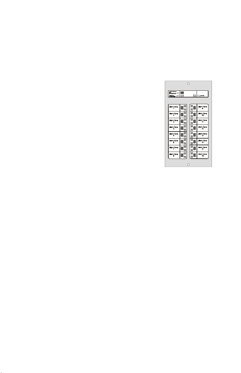
ACM-16ATF
Incorporates 16 red “point active” and 16 yellow
“trouble” LEDs, 16 momentary touch-pad switches
for controlling each point, a system trouble LED, an
On-line/Power LED, and a local piezo sounder with
a silence/acknowledge switch for audible
indication of alarm and trouble conditions at each
annunciator.
Height = 8-3/8" (21.27 cm)
Width = 4-3/8" (11.11 cm).
Note: In Canada this module must be used to
annunciate the fire alarm input points/zones only.
ACM-16ATCS4F (for use in Canada)
The ACM-16ATCS4 contains 12 red “point active”, four yellow “point
active”, and 16 yellow “trouble” LEDs, 16 momentary touch-pad switches
for controlling each point, a system trouble LED, an On-line/Power LED,
and a local piezo sounder with a silence/acknowledge switch for audible
indication of alarm and trouble conditions at each annunciator.
Note: In Canada this module must be used to annunciate supervisory and burglary
signals from associated points/zones.
ACM-16AT.cdr
ACM-16ATYF
Same as the ACM-16ATF, except that all LEDs are yellow (yellow On/Alarm
and yellow Trouble).
Note: In Canada this module must be used to annunciate supervisory and burglary
signals from associated points/zones.
Note: In Canada the color red may only be used to indicate active alarm inputs. The
color yellow may be used to indicate supervisory, burglary and trouble signals, and
the color green may be used to indicate the presence of power, or an activated
output.
ACM-16ATF/ACM-32AF Manual PN 51480:A0 02/02/01
11
Page 12

2. Inventory ACM-16ATF Series
Expander Modules
AEM-16ATF
Expands the ACM-16ATF Series by 16 system points. The unit is identical
in size and in frontal appearance to the control module. One to three of these
expander modules can be supported by a control module to a maximum of
64 system points.
Note: The AEM-16ATF Series cannot be used to expand the ACM-32AF. Expander
LED colors need not match the control module LED colors for the expander to
operate.
12
ACM-16ATF/ACM-32AF Manual PN 51480:A0 02/02/01
Page 13
ACM-32AF Series 2. Inventory
ACM-32AF Series
Control Modules
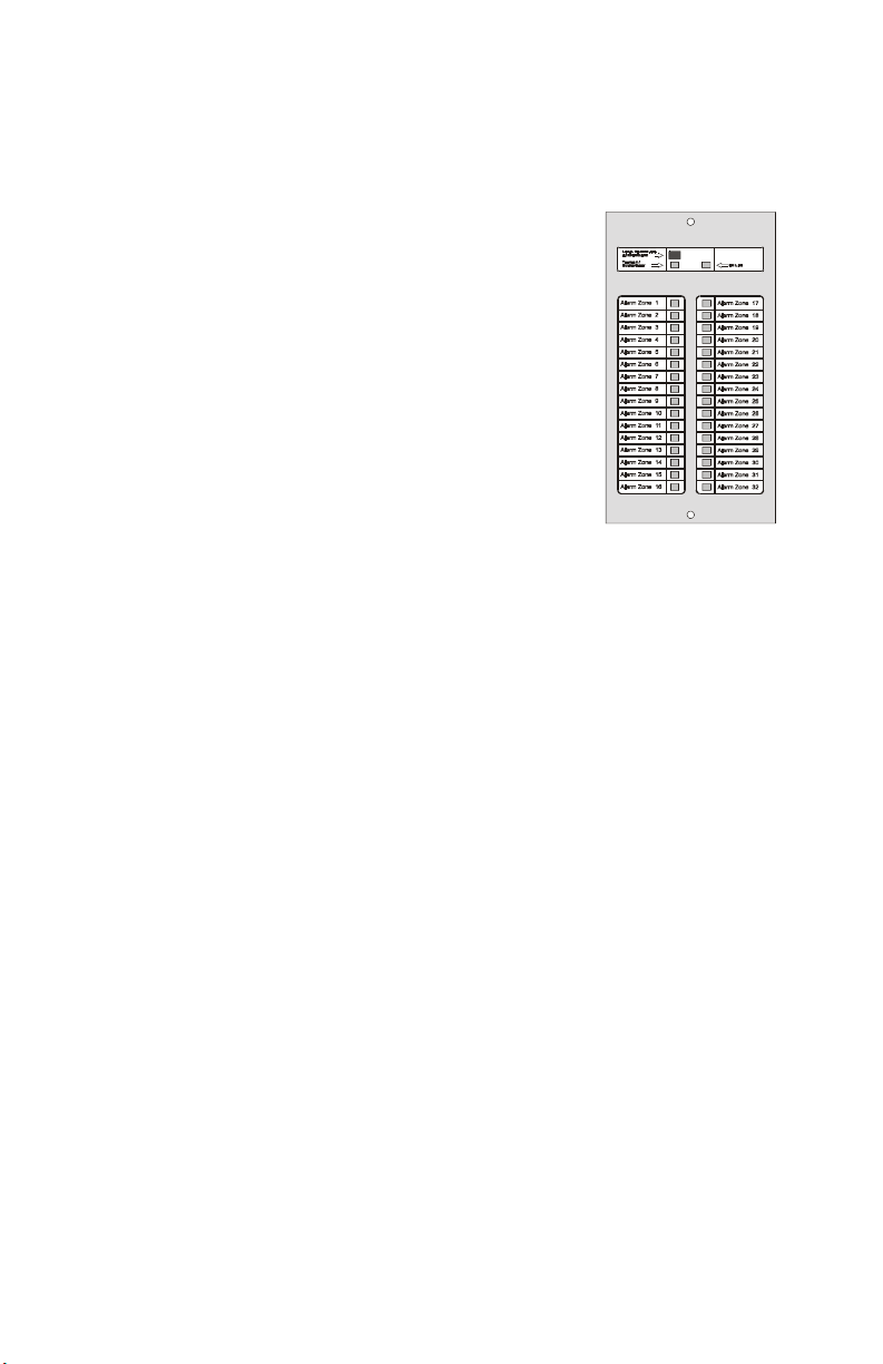
ACM-32AF
This control module contains 32 red “point active”
LEDs, a system “trouble” LED, an On-line/Power
LED, and a local piezo sounder with a
silence/acknowledge switch for audible indication
of alarm and trouble conditions at each annunciator.
Height = 8-3/8" (21.27 cm)
Width = 4-3/8" (11.11 cm).
Note: In Canada this module must be used to
annunciate the fire alarm input points/zones only.
Expander Modules
AEM-32AF
Expands the ACM-32AF Series by 32 system points. This unit is identical
in size and frontal appearance to the control module. One expander module
can be supported by a control module providing a maximum of 64 points.
Note: The AEM-32AF cannot be used to expand the ACM-16ATF Series control
modules.
ACM-32A.cdr
Note: In Canada the color red may only be used to indicate active alarm inputs. The
color yellow may be used to indicate supervisory, burglary and trouble signals, and
the color green may be used to indicate the presence of power, or an activated
output.
ACM-16ATF/ACM-32AF Manual PN 51480:A0 02/02/01
13
Page 14
2. Inventory Cabinet & Panel Hardware
Cabinet & Panel Hardware
Surface-Mount Backboxes
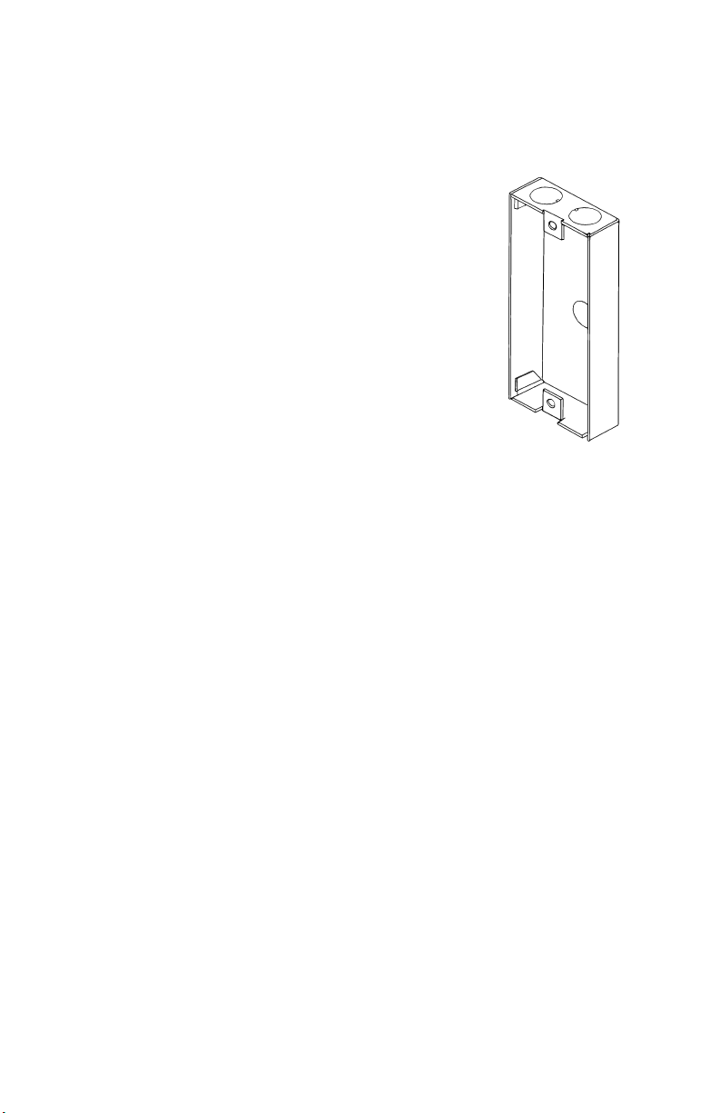
ABS-1F
This surface mounted backbox provides for the remote
mounting of a single ACM-16ATF Series or ACM32AF Series annunciator in a surface-mount enclosure.
Knockouts are provided for use with 1/2" conduit. The
annunciator mounts directly to the box without a dress
plate.
Height = 8-1/2" (21.59 cm)
Width = 4-1/2" (11.43 cm)
Depth = 1-3/8" (3.49 cm).
ABS-2F
This surface mounted backbox provides for the surface mounting of an
annunciator-expander combination. Knockouts are provided for use with
1/2" conduit. The annunciator module mounts directly to the box without
a dress plate.
Height = 8-1/2" (21.59 cm)
Width = 8-15/16" (22.7 cm)
Depth = 1-3/8" (3.49 cm).
Note: The ABS-1F and ABS-2F will not support the installation of the AKS-1
Annunciator Key Switch.
50439d2.tif
ABS-1TF
The ABS-1TF is a surface mounted backbox for mounting one ACS Series
annunciator. This backbox has an increased depth that allows mounting of
the AKS-1 Annunciator Key Switch.
Height = 9-15/16" (25.24 cm)
Width = 4-5/8" (11.75 cm)
Depth = 2-1/2" (6.35 cm).
14
ACM-16ATF/ACM-32AF Manual PN 51480:A0 02/02/01
Page 15
Cabinet & Panel Hardware 2. Inventory
Flush-mount Backboxes
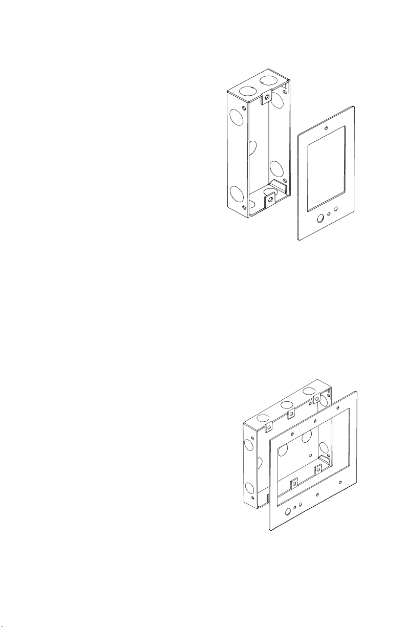
ABF-1F
This flush mounted backbox provides
for the remote mounting of a single
annunciator module in a flush-mount
enclosure. Knockouts are provided
for use with 1/2" conduit. Includes a
trim plate, mounting hardware, and an
adhesive-backed annunciator label
for the dress plate (15824).
Height = 9-15/16" (25.24 cm)
Width = 4-5/8" (11.75 cm)
Depth = 2-1/2" (6.35 cm).
Trim Plate dimensions 11" (27.94 cm) x 6-1/4" (15.875 cm)
ABF-2F
This flush mounted backbox provides for flush mounting of one annunciatorexpander combination. Includes a trim plate and an adhesive-backed
annunciator label for the dress plate (15824).
50439d3.tif
Height = 8-1/2" (21.59 cm), Width = 8-15/16" (22.7 cm)
Depth = 1-3/8" (3.49 cm)
Trim Plate dimensions - 11" (27.94 cm) x 10-5/8" (26.99 cm)]
ABF-4F
This flush mounted backbox provides for
the remote mounting of one to four
annunciator modules. Knockouts are
provided for use with 1/2" conduit.
Includes a trim plate and an annunciator
label.
Height = 9-15/16" (25.24 cm)
Width = 17-3/8" (44.13 cm)
Depth = 2-1/2" (6.35 cm).
Trim Plate dimensions 11" (27.94 cm) x 19-3/8" (49.21 cm)
ACM-16ATF/ACM-32AF Manual PN 51480:A0 02/02/01
50439d1.tif
15
Page 16

2. Inventory Cabinet & Panel Hardware
Semi Flush-mount Backboxes
ABF-1DF
This backbox mounts one Annunciator module
and includes an attractive smoked glass door
with keylock.
Box dimensions Height = 9-15/16" (25.24 cm)
Width = 4-5/8" (11.75 cm)
depth = 2-1/2" (6.35 cm).
Door dimensions Height = 10.713" (27.21 cm)
Width = 6" (15.24 cm)
Depth = 0.75" (1.9 cm).
ABF-2DF
Same as ABF-1DF except that two modules can be mounted.
Box dimensions Height = 9-15/16" (25.24 cm)
Width = 9-3/16" (23.37 cm)
Depth = 2-1/2" (6.35 cm)
Door dimensions Height = 10.713" (27.21 cm)
Width = 10.375" (26.35 cm)
Depth = 0.75" (1.9 cm).
ABF-1DF.cdr
16
ACM-16ATF/ACM-32AF Manual PN 51480:A0 02/02/01
Page 17

Cabinet & Panel Hardware 2. Inventory
Additional Hardware
ABM-1
The Annunciator Blank Module is a two-sided dress plate identical in
appearance to the front panel of the ACM-16ATF module on one side, and
the front panel of the ACM-32AF module on the other side. The blank
module covers unused module positions in the annunciator backbox or dress
panel.
Height = 8-3/8" (21.27 cm), Width = 4-3/8" (11.11 cm).
AKS-1F
The Annunciator Key Switch provides access security for the control
switches on the ACM-16ATF Series. The key switch kit includes a key and
hardware for mounting to the trim plate of a flush-mount type annunciator
enclosure. Also included is an adhesive-backed Annunciator Label for use
with the key switch/dress plate assembly.
Note: The AKS-1F can only be employed with a flush-mount type backbox.
ACM-16ATF/ACM-32AF Manual PN 51480:A0 02/02/01
17
Page 18

2. Inventory Cabinet & Panel Hardware
NOTES
18
ACM-16ATF/ACM-32AF Manual PN 51480:A0 02/02/01
Page 19
3. Design Considerations
Limits
The standard Fire•Lite EIA-485 circuit can drive up to 32 annunciators or
expanders. The number of annunciators that can engage in two-way
communication is dependent on the number of addresses available with a
given fire alarm control panel. The actual number of annunciator/expander
modules that can be powered in a particular system depends on the current
available from the control panel’s power supply.
Note: Refer to the instruction manual of the particular Fire Alarm Control Panel for
more details.
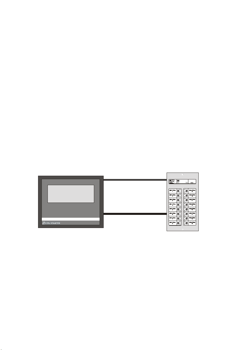
Wire Runs
Communication between the control panel and the annunciator occurs over
a power-limited 2-wire EIA-485 serial interface. This communication is
supervised by the fire alarm control panel. Each annunciator/expander
module also requires a filtered 24 VDC power connection. This power
circuit is inherently supervised; loss of power registers as a communication
failure at the control panel.
Fire Alarm Control Panel
ACS Power
Filtered & Power-limited
Annunciator
EIA-485 Circuit
(two-wire)
Power-limited & Supervised
Figure 1 Wire Run Diagram
Wiring Specifications
The EIA-485 circuit cannot be T-Tapped; it must be wired in a continuous
fashion. The maximum wiring distance is 6,000 feet at 16 AWG. The wiring
size must be a 12 AWG to 18 AWG twisted shielded pair cable having a
characteristic impedance of 120 ohms, +/- 20%. Limit the total wire
resistance to 100 ohms on the EIA-485 circuit, and 10 ohms on the
annunciator power circuit. Do not run cable adjacent to, or in the same
conduit as, 120 volts AC service, “noisy” electrical circuits that are powering
mechanical bells or horns, audio circuits above 25 volts RMS, motor control
circuits, or SCR power circuits.
ACM-16ATF/ACM-32AF Manual PN 51480:A0 02/02/01
ACSf-wirerun.cdr
19
Page 20
3. Design Considerations Receive Only and Transmit/Receive
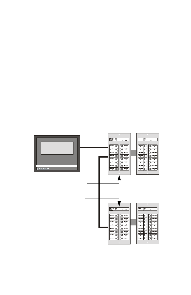
Receive Only and Transmit/Receive
For redundant annunciation of system points, annunciators can be
configured as “Receive Only” annunciators. Receive Only annunciators
must be set to the same address as the annunciators they duplicate. Receive
Only annunciators intercept information being transmitted to a
“Receive/Transmit” annunciator for duplication at an intermediate display
location. When configured for Receive Only operation, they cannot be used
to send information to the system, and as a result are not supervised by the
control panel. They cannot perform remote functions such as Acknowledge,
Silence, or Reset. Control switches on Receive Only annunciators can be
used only for local functions, such as Lamp Test. Wiring to Receive Only
annunciators may be supervised by installing the modules “upstream” of
fully supervised, Receive/Transmit annunciators along the EIA-485 line.
Annunciators that are configured to serve as full function annunciators can
both receive status information as well as transmit commands to the control
panel. This allows the annunciator to remotely execute functions of the
control panel in addition to displaying the status of the system.
Fire Alarm
Control Panel
“Receive Only” Annunciator set to
address “X” and installed upstream.
Full Function “Receive/Transmit”
Annunciator set to address “X”.
Figure 2 Receive/Transmit Annunciator Diagram
Two-wire
EIA-485
Circuit
Annunciator
Annunciator
Expander
ACSf-RTannun.cdr
Expander
20
ACM-16ATF/ACM-32AF Manual PN 51480:A0 02/02/01
Page 21

Electrical Ratings 3. Design Considerations
Electrical Ratings
Input Voltage: 24 VDC (must be filtered and power-limited).
Current Draw from 24 VDC Input: Standby Alarm
ACM-16ATF & ACM-32AF Series 0.040 amps 0.056 amps
AEM-16ATF & AEM-32AF Series 0.002 amps 0.018 amps
Data Communications Port: EIA-485 operating at 20 Kbps (must be powerlimited).
Annunciator Power Requirements
Annunciators draw their power from the control panel and must be
considered when calculating the primary and secondary power supply
requirements for the system. Each annunciator module is accounted for in
the power calculations outlined in the respective installation manual.
However, if the current draw dedicated to the annunciators must be
calculated as a separate figure, use the equations below:
Number of ACM modules [ ] X 0.040 = [ ] amps
Note: The 0.040 amps can be reduced to 0.030 for modules
with Piezo Disable or Flash Inhibit modes selected.
Number of AEM modules [ ] X 0.002 = [ ] amps
Total Annunciator Standby Current = [ ] amps
Number of ACM and AEM
modules assumed to be in alarm
simultaneously
Note: This entry assumes that all LEDs are lit
simultaneously. When the alarm system specification
permits, calculations can be based on a 10% alarm loading
capacity. For 10% capacity, enter 10% of the total number of
ACM and AEM modules multiplied by the number of remote
annunciator locations, but do not enter less than one.
Total Annunciator Alarm Current = [ ] amps
Table 2 Calculation of Power Requirements
ACM-16ATF/ACM-32AF Manual PN 51480:A0 02/02/01
[ ] X 0.016 = [ ] amps
21
Page 22

3. Design Considerations Annunciator Power Requirements
NOTES
22
ACM-16ATF/ACM-32AF Manual PN 51480:A0 02/02/01
Page 23

4. Installation
This section provides detailed instructions for installing and wiring
annunciator modules and expander modules.
Note: For wiring & programming details that are unique to a specific fire alarm
control panel, refer to that panel's appendix in this manual, and to the panel's
Instruction Manual.
Mounting the Backbox or Cabinet
Select appropriate knockout(s) on the enclosure for your wiring to run
through and snap it out.
Fasten the cabinet or backbox to the wall.
Ground the enclosure to a solid metallic ground, such as a grounded cold
water pipe.
Wiring and Connecting
Follow these guidelines when wiring and connecting the annunciator
circuit(s):
• The EIA-485 circuit must be wired using a twisted-shielded pair cable
having a Characteristic Impedance of 120 ohms, +/- 20%.
• Terminate the EIA-485 shield at the Fire Alarm Control Panel only.
• Do not run cable adjacent to, or in the same conduit as, 120-volt AC
service, noisy electrical circuits that are powering mechanical bells or
horns, audio circuits above 25 Vrms, motor control circuits, or SCR
power circuits.
• All enclosures, including the FACP backbox, must be connected to
earth ground.
• Never use the shield for grounding purposes.
ACM-16ATF/ACM-32AF Manual PN 51480:A0 02/02/01
23
Page 24

4. Installation Wiring and Connecting
Connect Wiring to Backbox or Cabinet
Pull all annunciator wiring into the enclosure and terminate as stated and
illustrated below:
When the EIA-485 shield is not in conduit:
• Terminate the shield at the outside of the FACP backbox (ground).
• Do not allow the shield to enter or even touch the cabinet.
• Between annunciators, wire-nut multiple shields together outside of
the respective enclosures.
Shield
ACSf-term1.cdr
Figure 3 Terminating Wiring Not In Conduit
When the EIA-485 shield is in conduit:
• Connect it to system reference (system common).
24
• The shield can enter the cabinet, but must be insulated from the cabinet
(no electrical contact).
• Between annunciators, wire-nut multiple shields together (which can
be inside of the respective enclosure, but cannot contact the enclosure).
Shield
ACSf-term2.cdr
Figure 4 Terminating Wiring In Conduit
ACM-16ATF/ACM-32AF Manual PN 51480:A0 02/02/01
Page 25

Wiring and Connecting 4. Installation
EIA-485 Circuit
Connect the EIA-485 annunciator circuit wiring to the removable terminal
blocks as illustrated below.
• Do not “T-Tap” the power-limited EIA-485 circuit. It will not function
properly.
• Leave the 120-ohm ELR (PN 71244) installed across the EIA-485
‘Out’ terminals at the last annunciator on the circuit. Remove this
resistor from all other annunciators.
• There is a maximum distance of 6000 feet between the panel and the
last annunciator on the EIA-485 circuit.
In
-
Out
Out
In
In
Out
Out
In
TB2 - Last
Annunciator
TB2 - Middle
Annunciator
-
+
+
-
-
+
+
– +
EIA-485 Circuit
from Control Panel
Figure 5 Connecting EIA-485 Wiring to Terminal Blocks
ACM-16ATF/ACM-32AF Manual PN 51480:A0 02/02/01
-
In
Out
Out
In
TB2 - First
Annunciator
ACS_eia.cdr
25
-
+
+
Page 26

4. Installation Wiring and Connecting
24 VDC Circuit
CAUTION: Power must be turned off when connecting the 24 VDC
!
power to the annunciator to avoid damaging the equipment.
Connect the 24 VDC annunciator wiring to the removable terminal blocks
as illustrated below:
• Power must be filtered, non-resettable, and power-limited.
• A Power Supervision Relay is not needed because the annunciator is
inherently supervised by the control panel (loss of EIA-485
communication is registered at the control panel during loss of power
to the annunciator).
• The power can be supplied by the FACP or a remote power supply listed
for fire protective signaling use.
• Connect Earth Ground to a mounting screw on the backbox or cabinet.
N/C Trouble Input
N/C Trouble Input
Common In
-
Common Out
-
Power In
+
Power Out
+
Earth Ground
TB1 on Last Annunciator
26
N/C Trouble Input
N/C Trouble Input
Common In
-
Common Out
-
Power In
+
Power Out
+
Earth Ground
TB1
N/C Trouble Input
N/C Trouble Input
Common In
-
Common Out
-
Power In
+
Power Out
+
Earth Ground
TB1
– +
24 VDC
Power
ACS_pwr.cdr
Figure 6 Connecting 24 VDC Wiring to Terminal Blocks
ACM-16ATF/ACM-32AF Manual PN 51480:A0 02/02/01
Page 27

Installing Labels 4. Installation
Installing Labels
Remove the center pages of this manual. If using the custom user display
labels, type the appropriate information on the labels. Carefully cut out the
labels and insert them into the annunciator or expander by slipping them into
the label slots on the back side of the annunciator face plate. To ensure the
best fit, cut directly along the dotted line surrounding each label.
Figure 7 Installing Labels
ACM-16ATF/ACM-32AF Manual PN 51480:A0 02/02/01
ACSf-labels.cdr
27
Page 28

4. Installation Setting Rotary and DIP Switches
Setting Rotary and DIP Switches
The Annunciator Address Rotory Switches and the DIP Switches must be
set before the annunciator will operate properly. The rotory switches are set
to the addresss of the annunciator. The DIP switches are set to determine how
the annunciator operates. For further information see the appendix for the
specific FACP.
J4 - Key Switch Connector
5
5
4
4
6
3
2
1
Annunciator Address
Rotory Switches
Tens Ones
5
4
6
3
2
9
1
0
Figure 8 Setting Rotory and DIP Switches
DIP Switch Settings
1 - Not Used: This switch must be set “OFF”
2 - Expanders Installed: None = OFF; One = ON; Two = OFF; Three = ON
3 - Expanders Installed: None = OFF; One = OFF; Two = ON; Three = ON
4 - Eight-Point Shift: Set switch “ON” to switch the CPU functions out of the first
eight annunciator points. This switch is intended for systems between 9 and 16
circuits and employing one ACM-16ATF module (with no expander) where
annunciation of all circuits is desired.
5 - Receive Only: Set this switch “ON” for each annunciator that will provide the
same information as another annunciator in a different location.
Note: When two or more annunciators hold the same address, all but one must be
configured as “Receive Only” annunciators.
6 - Piezo Disable: Set this switch “ON” to disable the piezo from sounding for any
event. (The piezo will also be disabled if Flash Inhibit is “ON”.)
7 - Switch Inhibit: To disable the point control switches on the annunciator from
executing system control functions, set this switch “ON”. When inhibited, the
switches will serve as local Lamp Test switches only. In addition, the
Acknowledge/Lamp Test switch will function only in a local capacity, unrecognized
by the control panel.
8 - Flash Inhibit: Set this switch “ON” to disable the flashing of LEDs associated
with unacknowledged events. Flash Inhibit also disables the piezo from sounding.
6
3
7
7
8
8
2
9
9
1
0
0
DIP Switches
Switch
Positions
5
4
7
3
8
2
1
0
Using a small screw
6
driver, rotate dials to
7
desired address.
8
This address is set to
9
‘02’ or ‘2’.
OFF ON
ACSf-switch.cdr
28
ACM-16ATF/ACM-32AF Manual PN 51480:A0 02/02/01
Page 29

Mounting Annunciators and Expanders 4. Installation
Mounting Annunciators and Expanders
Set the address Rotory Switches and DIP Switches as outlined in "Setting
Rotary and DIP Switches" on page 28 and the Appendix for specific fire
alarm control panels.
Install labels in annunciator module and expander module(s) as detailed in
"Installing Labels" on page 27.
Surface Mount Backbox (ABS Series)
1. Connect terminal blocks on circuit wiring in backbox to connectors on
annunciator.
2. Align the mounting holes on the annunciator with the threaded tabs on
the backbox and secure with the two screws provided. Tighten
securely.
Flush Mount Backbox (ABF Series)
ABF-1F Backbox Only.
1. Remove the backing from the gummed label and affix to the trim plate
as illustrated.
Note: If installing an Annunciator Key Switch (AKS-1F), use the label supplied with
the kit instead of the label that ships with the annunciator. Holes in label will align
with holes in trim plate.
ACSf-platelabel.cdr
Figure 9 Applying the Label
2. Place the trim plate face down, with the threaded studs facing up.
Position the annunciator over the threaded studs on the trim plate and
secure with the two nuts and lock washers provided. Tighten securely.
Nuts & Lockwashers
Annunciator
Studs
Figure 10 Assembling Trim Plate and Annunciator
ACM-16ATF/ACM-32AF Manual PN 51480:A0 02/02/01
Trim Plate
ACSf-platemtg.cdr
29
Page 30

4. Installation Mounting Annunciators and Expanders
3. If employing an AKS-1F Key Switch, mount it to the trim plate. Plug
the switch leads to connector J4 on the annunciator.
J4
Connector
AKS-1F Key
Switch
ACSf-akswire.cdr
Figure 11 Annunciator Key Switch
4. Plug terminal blocks on circuit wiring in backbox to connectors on
annunciator.
5. Align the mounting holes on the trim plate with the threaded tabs on
the backbox and secure with the two screws provided. Tighten
securely.
ABF-2F and ABF-4F Backboxes Only.
1. Remove the backing from the gummed label and affix to the trim plate
as illustrated in Figure 9 on page 29.
2. Connect annunciator expander(s) as detailed in "Wiring the Expander
Connections" on page 31.
3. Place the trim plate face down, with the threaded studs facing up.
Position the annunciator and expander(s) over the threaded studs on
the trim plate and secure each with the two nuts and lock washers
provided (see Figure 10 on page 29). Tighten securely.
4. If employing a keyswitch, mount it to the trim plate. Plug the switch
lead to Connector J4 on the annunciator (see Figure 11 on page 30).
5. Plug terminal blocks on circuit wiring in backbox to connectors on
annunciator.
6. Align the mounting holes on the trim plate with the threaded tabs on
the backbox and secure with the screws provided. Tighten securely.
30
ACM-16ATF/ACM-32AF Manual PN 51480:A0 02/02/01
Page 31

Wiring the Expander Connections 4. Installation
Semi-Flush Mount Backbox (ABF-1DF/-2DF)
Annunciators and expanders are mounted in these backboxes the same way
as they are mounted in the flush mounted type, except for the addition of the
following:
Aligning the door with the trim plate, slide it down onto the pins of the trim
plate. When positioned correctly, the door will open and close freely. Close
and lock door.
Dress Panel (ADP-4F)
1. Connect annunciator expander(s) as detailed in "Wiring the Expander
Connections" on page 31.
2. Place dress panel face down with the threaded studs facing up.
Position the annunciator and expanders over the threaded studs on the
dress panel and secure with the two nuts and lock washers provided, as
illustrated below.
Lockwashers & Nuts
Annunciator
Studs
Figure 12 Installing Annunciator on ADP-4F Dress Panel
Dress Panel
3. Align the annunciator/dress panel assembly with the holes into the
cabinet backbox. Secure the assembly with the screws provided.
4. Plug terminal blocks on circuit wiring of FACP to connectors on
annunciator.
5. Close dress panel and secure with quarter-turn screw.
Wiring the Expander Connections
Two Position Backbox (-2 Series)
If installing one ACM Series Annunciator and one AEM Series Expander in
the same enclosure perform the following steps:
• Plug one end of an Expander Ribbon Cable into connector J2 on the
annunciator module.
• Place the expander module in the second trim plate position.
• Connect the ribbon cable from the annunciator module to connector J3
on the expander module.
ACSf-panelmtg.cdr
ACM-16ATF/ACM-32AF Manual PN 51480:A0 02/02/01
31
Page 32

4. Installation Wiring the Expander Connections
Four Position Backbox (-4 Series) or Cabinet
ACM-16 Series/AEM-16ATF
If installing one ACM-16 Series annunciator with three AEM-16ATF
expanders on the same trim plate or dress panel, perform the following steps:
• Plug one end of an Expander Ribbon Cable into connector J2 on the
annunciator module.
Place the expander module in the second position.
Connect the ribbon cable from the annunciator module to connector J3
on the expander module.
• Connect one end of a ribbon cable to connector J2 on the first expander
module.
Place the second expander module in the third position.
Connect the other end of the expander ribbon from the first expander
module to Connector J3 on the second expander module.
• Connect one end of a ribbon cable to Connector J2 on the second
expander module.
Place the third expander module in the fourth position.
Connect the other end of the ribbon cable from the second expander
module to Connector J3 on the third expander module.
ACM-32AF/AEM-32AF
If installing a second set of ACM-32AF/AEM-32AF annunciator/expander
modules in the same dress panel or trim plate, repeat the following steps for
installation of positions three and four:
• Plug terminal blocks on circuit wiring in backbox to connectors on the
second annunciator set.
Note: A 120-ohm ELR must remain installed across the EIA-485 line at the
last annunciator on the circuit.
• Place the annunciator module in position three.
• Plug one end of an Expander Ribbon Cable into connector J2 on the
annunciator module.
• Place the expander module in the fourth position.
• Connect the ribbon cable from the annunciator module to connector J3
on the expander module.
32
ACM-16ATF/ACM-32AF Manual PN 51480:A0 02/02/01
Page 33

Supervising Devices 4. Installation
Supervising Devices
The normally closed Trouble Input can be used for supervising local power
sources or other devices. If employed, all changes in status (to and from the
trouble state) will be sent to the control panel in the event of device failure
or restoral.
If not used, a jumper must be installed across the terminals. Without this
jumper, the control panel will register a trouble condition.
Device to be
supervised
5 VDC @ 0.5 mA
Normally closed
trouble contacts
Figure 13 Connection of Supervising Devices
TB1 on
Annunciator
Trouble Input
Main Power Supply Connections
The annunciator modules can be powered by an MS-9200 or MS-9600
internal power supply, an APS-6RF, FCPS-24F or an MPS-24 Series power
supply. The power run to the annunciator need not contain a Power
Supervision Relay because loss of power is inherently supervised through
communication loss. For details about connecting the annunciator to a
particular fire control panel, see the appropriate appendix in this manual.
Programming and Testing the Annunciators
After annunciator installation is complete, program the Fire Alarm Control
Panel to accept the annunciators as explained in the programming section of
the panel’s manual.
ACSf-super.cdr
After programming, fully test the system to ensure that each switch performs
its intended function, that each LED lights, and that the annunciators can
perform the functions outlined in "5. LED and Switch Functions" on page 37.
ACM-16ATF/ACM-32AF Manual PN 51480:A0 02/02/01
33
Page 34

Remove Center Pages for Slide-In Labels
ACM-16ATF & AEM-16ATF Labels
Two labels are required for the ACM-16ATF or the AEM-16ATF, one for the
left side and one for the right side of each module. Each label has a distinctive
format. See "Installing Labels" on page 27 for more information on these
labels.
Set A: Sensiscan 200 & Sensiscan 2000 - A label set that provides a
label (#1) for system control functions & system status, and blank labels
(#2 - #7) for one control module and three expander modules.
Set B: MS-9200 - A label set that provides a label (#1) for system control
functions & system status. Use with Set A, Labels #2 - #8 to provide blank
labels for one control module and three expander modules.
Set C: MS-9600 - A label set that provides a label (#1) for system control
functions & system status. Use with Set A, Labels #2 - #8 to provide blank
labels for one control module and three expander modules.
Set D: All Panels - This extra set of blank labels provides for customized
information by the user for a control module.
To create custom slide-in labels for the ACM series annunciators, visit
Fire•Lite’s web site at ‘www.firelite.com’ and click on ‘Label•Lite’.
34
ACM-16ATF/ACM-32AF Manual PN 51480:A0 02/02/01
Page 35

Remove Center Pages for Slide-In Labels
ACM-32AF & AEM-32AF Labels
Two labels are required for the ACM-32AF or the AEM-32AF, one for the
left side and one for the right side of each module. Each label has a distinctive
format. See "Installing Labels" on page 27 for more information on these
labels.
Set E: Sensiscan 200 & Sensiscan 2000 - A label set that provides a
label (#1) for system status, and blank labels (#2 - #4) for one control module
and one expander modules.
Set F: MS-9200 & MS-9600 - A label set that provides a label (#1) for
system status, and blank labels (#2 - #4) for one control module and one
expander modules.
Set G: All Panels - This extra set of blank labels provides for customized
information by the user for a control module.
ACM-16ATF/ACM-32AF Manual PN 51480:A0 02/02/01
35
Page 36

NOTES
36
ACM-16ATF/ACM-32AF Manual PN 51480:A0 02/02/01
Page 37

5. LED and Switch Functions
ACM-16ATF
The following is a description of the various LEDs and switches located on
the ACM-16ATF.
Local Silence/Acknowledge
Switch
On-Line LED
System Trouble LED
Point-Active LED
Trouble LED
Control Switch
ACM-16AT.cdr
Figure 14 ACM Series LED & Switch Locations
Local Silence/Acknowledge Switch - This switch performs multiple
functions:
• When pressed, it first lights all the LEDs (except the On-line LED) on
the module and then each expander. Piezo sounds for as long as the
switch is held down.
• It acknowledges all status changes for both the annunciator and the
expanders. Flashing LEDs will latch on solid and the piezo will be
silenced.
On-line LED - Flashes green during communication with the control
panel.
ACM-16ATF/ACM-32AF Manual PN 51480:A0 02/02/01
37
Page 38

5. LED and Switch Functions ACM-16ATF
System Trouble LED - Glows yellow for all trouble conditions in the
system, including points or zones not mapped to the annunciator/expanders.
Point-Active LED - Flashes to indicate an active point; after being
acknowledged it glows until reset.
Note: LED color varies by model number; see chart below.
Trouble LED - Flashes to indicate a trouble situation. After being
acknowledged it glows until reset. If communication with control panel is
broken, all trouble LEDs flash.
Note: LED color varies by model number; see chart below.
Control Switch - Functions as a local Lamp Test for the two LEDs
dedicated to a point. Control switches can be used to execute such system
functions as ACKNOWLEDGE, SIGNAL SILENCE, and SYSTEM
RESET. Switches can also be used to control the status of various output
circuits.
The table below describes the differences of the LED colors on the various
modules.
ACM-16ATF ACM-16ATYF ACM-16ATCS4F
Color of
Point-active LED
Color of Trouble
LED
Red Yellow 12 Red,
4 Yellow
Yellow Yellow Yellow
Table 3 ACM Series LED Colors
38
ACM-16ATF/ACM-32AF Manual PN 51480:A0 02/02/01
Page 39

AEM-16ATF 5. LED and Switch Functions
AEM-16ATF
The following is a description of the various LEDs and switches located on
the AEM-16ATF.
Lamp Test Switch
Inactive LEDs
Point-Active LED
Trouble LED
Control Switch
AEM-16AT.cdr
Figure 15 AEM-16ATF Series LED & Switch Locations
Lamp Test Switch - When pressed, it lights all the LEDs (except the On-
line LED) on the expander and sounds the piezo for as long as the switch is
held down.
Inactive LEDs - These two LEDs are not functional on expander modules.
Point-Active LED - Flashes to indicate an active point; after being
acknowledged it glows until reset.
Trouble LED - Flashes to indicate a trouble situation. After being
acknowledged it glows until reset. If communication with control panel is
broken, all trouble LEDs flash.
Control Switch - Functions as a local Lamp Test for the two LEDs
dedicated to this point. Control switches can be used to execute such system
functions as ACKNOWLEDGE, SIGNAL SILENCE, and SYSTEM
RESET. Switches can also be used to control the status of various output
circuits.
ACM-16ATF/ACM-32AF Manual PN 51480:A0 02/02/01
39
Page 40

5. LED and Switch Functions ACM-32AF
ACM-32AF
The following is a description of the LEDs and the switch located on the
ACM-32AF.
Local Silence/Acknowledge
Switch
On-Line LED
System Trouble LED
Point-Active LED
ACM-32A.cdr
Figure 16 ACM-32AF LED & Switch Locations
Local Silence/Acknowledge Switch - This switch performs multiple
functions:
• When pressed, it first lights all the LEDs (except the On-line LED) on
the annunciator and then each expander. Piezo sounds for as long as the
switch is held down.
• It acknowledges all status changes for both the annunciator and the
expanders. Flashing LEDs will latch on solid and the piezo will be
silenced.
On-line LED - Flashes green during communication with the control
panel.
System Trouble LED - Glows yellow for all trouble conditions in the
system, including points or zones not mapped to the annunciator/expanders.
Flashes if communication with control panel is broken.
Point-Active LED - Flashes to indicate an active point; after being
acknowledged it glows until reset.
Note: Loss of communication with the control panel is monitored & reported by the
ACM-32AF. If connection between ACM-32AF & AEM-32AF fails, the ACM-32AF
will show a trouble condition and the main control panel will show annunciator-point
trouble.
40
ACM-16ATF/ACM-32AF Manual PN 51480:A0 02/02/01
Page 41

AEM-32AF 5. LED and Switch Functions
AEM-32AF
The following is a description of the LEDs and the switch located on the
AEM-32AF.
Lamp Test Switch
Inactive LED
Point-Active LED
AEM-32A.cdr
Figure 17 AEM-32AF LED & Switch Locations
Lamp Test Switch - When pressed, it lights all the LEDs (except the On-
line LED) on the expander module and sounds the piezo for as long as the
switch is held down.
Inactive LEDs - These two LEDs are not functional on expander modules.
Point-Active LED - Flashes to indicate an active point; after being
acknowledged it glows until reset.
Note: Loss of communication with the control panel is monitored & reported by the
ACM-32AF. If connection between ACM-32AF & AEM-32AF fails, the ACM-32AF will
show a trouble condition and the main control panel will show annunciator-point
trouble.
UDACT-F and Annunciators
The use of a UDACT-F (Universal Digital Alarm Communicator/
Transmitter) and an annunciator module on the same control panel will alter
the assignments of the trouble LEDs on annunciator points 3, 4, 5, 6, 7, and
8. Refer to the UDACT-F installation manual and the literature for the
respective fire alarm control panel for further details.
ACM-16ATF/ACM-32AF Manual PN 51480:A0 02/02/01
41
Page 42

5. LED and Switch Functions UDACT-F and Annunciators
NOTES
42
ACM-16ATF/ACM-32AF Manual PN 51480:A0 02/02/01
Page 43

Appendix A: Sensiscan 200
Capabilities
When installed with a Sensiscan 200, the modules can annunciate the status
of initiating and notification circuits, relays, and several system control
functions. Up to 32 devices can be connected to the EIA-485
communications output, all addresses combined. Two way communications
can occur with only one annunciator set to address “1”; other devices must
be configured as “Receive Only”. Check battery calculation tables for power
limitations. Each annunciator LED is auto matically assigned to one and only
one system point:
Circuits:
• IZ-4F, IZ-4AF, IZ-8F Initiating Device Circuits (alarm and trouble)
• IC-4F, ICE-4F, ICR-4LF Notification Appliance Circuits (activation
and trouble)
• CR-4F, CRE-4F, CR-4LF Control relays (activation and trouble)
• TC-2F, TC-4F circuits (activation and trouble)
System Controls:
• Acknowledge
• Signal Silence
•System Reset
• Activate Notification Circuits 1 and 2, the Rem ote Signaling Municipal
Tie circuit, and the Alarm Relay.
Connecting EIA-485 Circuit
Communication between the CPU and the annunciator module is
accomplished over a two-wire EIA-485 serial interface.
• Power-limited and supervised.
• 6000 feet maximum distance (with 16 AWG wire) between the control
panel and the furthest annunciator.
• Use twisted pair cable with a characteristic impedance of
approximately 120 ohms.
• EIA-485 circuit rated 5.5 VDC max., 60 mA max.
ACM-16ATF/ACM-32AF Manual PN 51480:A0 02/02/01
43
Page 44

Appendix A: Sensiscan 200 Providing Power to Annunciators
This communication circuit is supervised by the Sensiscan 200. Loss of
communication results in “System Trouble” and “Module Failure”
indications at the CPU.
Note: “System Trouble” and “Module Failure” will occur if the normally closed
supervisory path between Trouble Input Terminals of TB1 on the annunciator is
opened (or the jumper has not been installed).
The EIA-485 circuit is connected between the EIA-485 Interface on the CPU
and terminal TB2 on the annunciator.
EIA-485 Interface
on CPU of the
Sensiscan 200
– +
TB2
ACSf-s200.cdr
Figure 18 EIA-484 Circuit Connections - Sensiscan 200
Providing Power to Annunciators
Sensiscan 200 panels use the MPS-24BF Main Power Supply. No more than
200mA current can be drawn from these terminals in standby or alarm. This
24 VDC output is filtered, regulated, power-limited, and non-resettable.
The power run to the annunciator does not require a Power Supervision Relay
because loss of power is inherently supervised through a communications
loss.
Note: When not using the trouble input on annunciator or expander, jumper Trouble
Input terminals of TB1 on annunciator together.
Connect the power run for the annunciator module to TB2 Terminals 3(+)
and 4(–) as shown below.
(+) 24 VDC Non-Resettable Power
(–) Common
BATT –BATT +
1 2
TB3
TB1
ACM-16ATF/ACM-32AF Manual PN 51480:A0 02/02/01
44
COMMON COMMON
1 2 3 4
TB2
MPS-24BF Terminal Blocks
Figure 19 Power Connections - Sensiscan 200
ACSf-mps24b.cdr
Page 45

Program Mapping Appendix A: Sensiscan 200
Program Mapping
Annunciator points “track” or follow those system points they are
programmed to annunciate; they do not latch. The table outlines the
annunciation of various system circuits and functions.
Note: Control Switches marked “not used” will still function as local LAMP TEST or
local ACKNOWLEDGE switches for their respective points.
ACM-16ATF & AEM-16ATF
Circuit Type
IZ-4F, IZ-4AF,
IZ-8F circuit
IC-4F, ICE-4F,
ICR-4LF circuit
CR-4F, CRE-4F,
CR-4LF circuit
TC-2F, TC-4F
circuit
Annunciator
Point #1
Annunciator
Point #2
Annunciator
Point #3
Annunciator
Point #4
Annunciator
Point #5
Annunciator
Point #6
Annunciator
Point #7
Annunciator
Point #8
1. These control switches are active only if: DIP Switch #5 (Receive Only) is ‘OFF’ and DIP Switch #7
2. With Software P/N #S500R4.0 or higher installed in the Sensiscan 200, the manner in which the
3. ICR-4LF and CR-4LF circuits are annunciated as points 41-44 when installed behind the middle
4. If the Eight-Point Shift (DIP switch # 4) is set “ON,” the eight CPU functions will be shifted out of
5. Annunciator Point #7 yellow LED indicates Municipal Tie trouble if no UDACT-F is installed. It will
3
4
(Switch Inhibit) is ‘OFF’.
IZ-8Fcircuits programmed as supervisory are annunciated depends upon whether Mode 1 or Mode 2
is selected.
module or points 49-52 when installed behind the right-hand side module.
annunciator points 1 through 8. Those eight points will annunciate the first module.
annunciate Low Battery/Ground Fault if a UDACT-F is installed in the system.
Table 4 Annunciator Program Mapping - Sensiscan 200
ACM-32AF
AEM-32AF
Red LED Yellow LED
Indicates alarm status of
2
circuit
Indicates Activation
3
Indicates Activation
Indicates Activation
Indicates System Alarm
Not used
Not used Not used SYSTEM RESET
Not used
Indicates that
Notification Circuit #1
has been activated
Indicates that
Notification Circuit #2
has been activated
Indicates that Remote
Signaling Municipal Tie
has been activated
Indicates that Alarm
Relay has been activated
Indicates trouble
status of circuit
Indicates trouble
status of circuit
Indicates trouble
status of relay
Indicates trouble
status of relay
Indicates System
Trouble
Indicates that signals
have been silenced
Indicates Supervisory
condition
Indicates trouble
status of circuit
Indicates trouble
status of circuit
Indicates trouble
status of circuit
Indicates AC Fail Controls Alarm Relay
5
Control Switch
Not used
Controls Notification
Circuit
Controls Relays
Remote Switch
Functions
ACKNOWLEDGE
SIGNAL SILENCE
Not used
Controls Notification
Circuit #1
Controls Notification
Circuit #2
Controls Remote
Signaling Municipal
Tie
1
ACM-16ATF/ACM-32AF Manual PN 51480:A0 02/02/01
45
Page 46

Appendix A: Sensiscan 200 Program Mapping
NOTES
46
ACM-16ATF/ACM-32AF Manual PN 51480:A0 02/02/01
Page 47

Appendix B: Sensiscan 2000
Capabilities
When installed with a Sensiscan 2000, the modules can annunciate the status
of initiating and notification circuits, relays, and several system control
functions. Each annunciator LED is automatically assigned to one and only
one system point.
Note: To operate the annunciator module, the CPU must be Revision D or greater.
The revision level of the CPU is marked on a label affixed to the upper board.
Additionally, the system must be operating under CPU software with U4 ROM part
number 73085 or higher.
Circuits:
• IZM-8F Initiating Device Circuits (alarm and trouble)
• ICM-4F / ICE-4F Notification Appliance Circuits (trouble)*
• CRM-4F / CRE-4F Control relays (trouble)*
• TCM-2F circuits (trouble)*
• TCM-4F circuits (trouble)*
• VCM-4F / DCM-4F circuits (trouble)*
*Indication of output circuit activation can be obtained by
programming the CPU for “OUTPUT STATUS.”
System Controls:
• Acknowledge
• Signal Silence
•System Reset
• Activate Notification Circuits 1 and 2, the Rem ote Signaling Municipal
Tie circuit, and the Alarm Relay.
Configuring for the Sensiscan 2000
The annunciator can be set for addresses 1 or 2. The actual mapping
arrangement for a respective annunciator module and its expanders depends
on System annunciator programming. Refer to the Sensiscan 2000 Manual
for a more detailed explanation.
ACM-16ATF/ACM-32AF Manual PN 51480:A0 02/02/01
47
Page 48

Appendix B: Sensiscan 2000 Connecting the EIA-485 Circuit
Connecting the EIA-485 Circuit
Communication between the control panel and the annunciator module is
accomplished over a two-wire EIA-485 serial interface.
• Power-limited and supervised.
• 6000 feet maximum distance (with 16 AWG wire) between the control
panel and the furthest annunciator.
• Use twisted pair cable with a characteristic impedance of
approximately 120 ohms.
• EIA-485 circuit rated 5.5 VDC max., 60 mA max.
This communication circuit is supervised by the Sensiscan 2000. Loss of
communication results in “System Trouble” and “Module Failure”
indications at the CPU.
Note: “System Trouble” and “Module Failure” will also occur if the normally closed
supervisory path between TB1 Terminals on the annunciator is opened (or the
jumper has not been installed).
The EIA-485 circuit is connected between the EIA-485 Interface on the CPU
and terminal TB2 on the annunciator.
48
EIA-485 Interface
on CPU of the
Sensiscan 2000
– +
TB2
ACSf-s200.cdr
Figure 20 EIA-485 Circuit Connections - Sensiscan 2000
ACM-16ATF/ACM-32AF Manual PN 51480:A0 02/02/01
Page 49

Providing Power to Annunciators Appendix B: Sensiscan 2000
Providing Power to Annunciators
Sensiscan 2000 panels use the MPS-24AF or the MPS-24BF Main Power
Supply. This 24 VDC output is filtered, regulated, power-limited, and nonresettable.
MPS-24AF - 3 A maximum current draw
MPS-24BF - 200 mA maximum current draw
The power run to the annunciator does not require a Power Supervision Relay
because loss of power is inherently supervised through a communications
loss.
Note: When not using the trouble input on annunciator or expander, jumper Trouble
Input terminals of TB1 on annunciator together.
MPS-24AF Main Power Supply - Connect the power run for the
annunciator module to the MPS-24AF TB3 Terminals 3(+) & 4(–), as shown
below.
(+) 24 VDC NonResettable Power
(–) Common
BAT + BAT -
TB2
MPS-24AF Terminal Blocks
POWER LIMITED
+24R CO MM ON +24
COMMON
TB1
Figure 21 MPS-24AF Power Connections - Sensiscan 2000
MPS-24BF Main Power Supply - Connect the power run for the
annunciator module to the MPS-24BF TB2 Terminals 3(+) & 4(–)as shown
below.
(+) 24 VDC Non-Resettable Power
(–) Common
COMMON COMMON
1 2 3 4
TB2
MPS-24BF Terminal Blocks
Figure 22 MPS-24BF Power Connections - Sensiscan 2000
ACM-16ATF/ACM-32AF Manual PN 51480:A0 02/02/01
1 2
BATT –BATT +
TB3
TB1
ACSf-mps24a.cdr
ACSf-mps24b.cdr
49
Page 50

Appendix B: Sensiscan 2000 Installing Modules in the System
Installing Modules in the System
The annunciator modules begin annunciation with the CPU and continue
with the annunciation of circuits on the module installed directly after the
CPU. To ensure full employment of annunciator points, mount system
modules that require annunciation in the CPU row first, then in the second
row, etc. Modules with circuits that need not be annunciated by the system
should be installed further down in the cabinet.
Note: Without invoking the Eight-Point Shift, the first eight points would be dedicated
to CPU functions, not circuits of the first module. Refer to "Setting Rotary and DIP
Switches" on page 28.
CPU Side View
Top Row: Annunciator Address “1”
Points 1-32, annunciated by either the first
ACM-16ATF and its first expander, or by
the first ACM-32AF.
2nd Row: Annunciator Address “1”
Points 33-64, annunciated by either the
second and third expanders of an ACM16ATF, or by an AEM-32AF expander.
3rd Row: Annunciator Address “2”
Points 65-96, annunciated by either the
second ACM-16ATF and its first expander,
or by the second ACM-32AF.
50
4th Row: Annunciator Address “2”
Points 97-128, annunciated by either the
second and third expanders of the second
ACM-16ATF, or by an AEM-32AF.
Figure 23 CPU Module Ribbon Cable Connections
ACM-16ATF/ACM-32AF Manual PN 51480:A0 02/02/01
ACSf-instmods.cdr
Page 51

Program Mapping Appendix B: Sensiscan 2000
Program Mapping
Annunciator points “track” or follow those system points they are
programmed to annunciate; they do not latch. The table outlines the
annunciation of various system circuits and functions.
Note: Control Switches marked “not used” will still function as local LAMP TEST or
local ACKNOWLEDGE switches for their respective points.
ACM-16ATF & AEM-16ATF
Circuit Type
IZM-8F circuit
ICM-4F, ICE-4F
circuit
CRM-4F, CRE4F circuit
TCM-2F, TCM4F, VCM-4F,
DCM-4F circuit
Annunciator
5
Point #1
Annunciator
Point #2
Annunciator
Point #3
Annunciator
Point #4
Annunciator
Point #5
Annunciator
Point #6
Annunciator
Point #7
Annunciator
Point #8
1. These control switches are active only if: DIP Switch #5 (Receive Only) is ‘OFF’ and DIP Switch #7
(Switch Inhibit) is ‘OFF’.
2. With Software P/N #S500R4.0 or higher installed in the Sensiscan 2000, the manner in which the
IZM-8F circuits programmed as supervisory are annunciated depends upon whether Mode 1 or Mode
2 is selected.
3. These status LEDs are active only when the system is programmed for “Output Status”.
4. These control switches require that the system be programmed for “Output Control”.
5. If the Eight-Point Shift (DIP switch # 4) is set “ON,” the eight CPU functions will be shifted from
annunciator points 1 through 8 to points 57 through 64 (provided those points exist in the system).
6. Annunciator Point #7 yellow LED indicates Municipal Tie trouble if no UDACT-F is installed. It will
annunciate Low Battery/Ground Fault if a UDACT-F is installed in the system.
Table 5 Annunciator Program Mapping - Sensiscan 2000
ACM-32AF
AEM-32AF
Red LED Yellow LED
Indicates alarm status of
2
circuit
Indicates Activation
Indicates Activation
Indicates Activation
Indicates System Alarm
Not used
Not used Not used SYSTEM RESET
Not used
Indicates that
Notification Circuit #1
has been activated
Indicates that
Notification Circuit #2
has been activated
Indicates that Remote
Signaling Municipal Tie
has been activated
Indicates that Alarm
Relay has been activated
Indicates trouble
status of circuit
Indicates trouble
3
status of circuit
Indicates trouble
3
status of relay
Indicates trouble
3
status of relay
Indicates System
Trouble
Indicates that signals
have been silenced
Indicates Supervisory
condition
Indicates trouble
status of circuit
Indicates trouble
status of circuit
Indicates trouble
status of circuit
Indicates AC fail
module/panel trouble
6
Control Switch
Not used
Controls Notification
4
Circuit
Controls Relays
Remote Switch
Functions
ACKNOWLEDGE
SIGNAL SILENCE
Not used
Controls Notification
Circuit #1
Controls Notification
Circuit #2
Controls Remote
Signaling Municipal
Tie
Controls Alarm Relay
4
1
4
ACM-16ATF/ACM-32AF Manual PN 51480:A0 02/02/01
51
Page 52

Appendix B: Sensiscan 2000 Program Mapping
NOTES
52
ACM-16ATF/ACM-32AF Manual PN 51480:A0 02/02/01
Page 53

Appendix C: MS-9200
Capabilities
The MS-9200 allows annunciators to be programmed by zone or by point.
The EIA-485 serial interface will allow up to 32 annunciators, but two-way
communications can occur with only one annunciator per address. The other
devices must be configured as “Receive Only”.
When the panel is programmed by zone, annunciator address 1 is available,
and the annunciator modules display the 56 software zones of the MS-9200.
When the panel is programmed by point, 198 points are available.
Annunciator addresses 1, 2, 3, and 4 can be used, but only address 1 is
supervised.
The furthest annunciator can be 6000 feet from the fire alarm control panel
(check power limitations).
CAUTION: Annunciators on the MS-9200 can not be used for manual
!
control of Control modules, NACs, or relays (except for global Silence
and Drill switches).
Connecting the EIA-485 Circuit
Communication between the MS-9200 and the annunciator modules is
accomplished over a two-wire EIA-485 serial interface.
• Power-limited and supervised.
• 6000 feet maximum distance (with 16 AWG wire) between the control
panel and the furthest annunciator.
• Use twisted pair cable with a characteristic impedance of
approximately 120 ohms.
• EIA-485 circuit rated 5.5 VDC max., 60 mA max.
This communication circuit is supervised by the MS-9200. Loss of
communication results in “System Trouble” and “Module Failure”
indications at the CPU.
Note: “System Trouble” and “Module Failure” will also occur if the normally closed
supervisory path between TB1 Terminals on the annunciator is opened (or the
jumper has not been installed).
Continued on the next page...
ACM-16ATF/ACM-32AF Manual PN 51480:A0 02/02/01
53
Page 54

Appendix C: MS-9200 Providing Power to Annunciators
The EIA-485 circuit is connected between the ACS Mode connector (TB5)
on the main circuit board to terminal TB2 on the annunciator (see Figure 5
on page 25).
+ –
ACS SHIELD SLC SLC
1 COMM 2
A B B+ A+ B- A-
T
B
5
TB5 - ACS Mode
connector
T
B
6
TB2
ACSf-9200.cdr
Figure 24 EIA-485 Circuit Connections - MS-9200
Providing Power to Annunciators
The MS-9200’s 24 VDC main power supply is contained on its main circuit
board. No more than 300 mA current can be drawn from these terminals in
standby or alarm. This 24 VDC output is filtered, regulated, power-limited,
and non-resettable.
The power run to the annunciator need not r equire a Power Supervision Relay
because loss of power is inherently supervised through a communication
loss.
Note: When not using the trouble input on annunciator or expander, jumper Trouble
Input terminals of TB1 on annunciator together.
The power circuit is connected between terminal TB4 on the MS-9200 and
terminal TB1 on the annunciator (see Figure 6 on page 26) as shown below.
(+) 24 VDC NonResettable Power
TB1
ACM-16ATF/ACM-32AF Manual PN 51480:A0 02/02/01
54
(–) Common
+ –
24V UNREG 24V NONRS 2 4V RST
T
B
4
TB4 - Power Supply
Terminal Blocks
Figure 25 Power Supply Connections - MS-9200
ACSf-9200pwr.cdr
Page 55

Program Mapping Appendix C: MS-9200
Program Mapping
Annunciator points “track” or follow those system points they are
programmed to annunciate; they do not latch. The table outlines the
annunciation of system functions.
Note: Control Switches marked “No Function” will still function as local LAMP TEST
or local ACKNOWLEDGE switches for their respective points.
ACM-16ATF & AEM-16ATF
Annunciator
1
Point
Point #1
Point #2 Not used
Point #3 Not used Not used SYSTEM RESET
Point #4 Not used Not used DRILL
Point #5 Not Used
Point #6 Not Used
Point #7 Not Used
Point #8 Not Used Indicates AC Fail No Function
1. If the Eight-Point Shift (DIP switch # 4) is set “ON,” the eight CPU functions will be shifted from
annunciator points 1 through 8 to points 57 through 64 (provided those points exist in the system).
2. These control switches are active only if: DIP Switch #5 (Receive Only) is ‘OFF’ and DIP Switch
#7 (Switch Inhibit) is ‘OFF’.
3. Supervisory Point lights its associated zone red LED and annunciator point #5 yellow
LED.
ACM-32AF
AEM-32AF
Red LED Yellow LED
Indicates System
Alarm
Indicates System
Trouble
Indicates Alarm
Silenced
Indicates Supervisory
Condition
Indicates Maintence
Alert
Indicates Low Battery
and NAC Trouble
Control Switch
ACKNOWLEDGE
ALARM SILENCE
3
No Function
No Function
No Function
Table 6 Annunciator Program Mapping - MS-9200
2
ACM-16ATF/ACM-32AF Manual PN 51480:A0 02/02/01
55
Page 56

Appendix C: MS-9200 Program Mapping
NOTES
56
ACM-16ATF/ACM-32AF Manual PN 51480:A0 02/02/01
Page 57

Appendix D: MS-9600
Capabilities
The MS-9600 allows annunciators to be programmed by zone or by point.
The EIA-485 serial interface will allow up to 32 annunciators, but two-way
communications can occur with only one annunciator per address. The other
devices must be configured as “Receive Only”.
When the panel is programmed by zone, annunciator address 1 is available,
and the annunciator modules displays the 99 software zones of the MS-9600.
When the panel is programmed by point, 318 points are available per SLC
loop. Annunciator addresses 1, 2, 3, and 4 can be used, but only address 1
is supervised.
The furthest annunciator can be 6000 feet from the fire alarm control panel
(check power limitations).
CAUTION: Annunciators on the MS-9600 can not be used for manual
!
control of Control modules, NACs, or relays (except for global Silence
and Drill switches).
Connecting the EIA-485 Circuit
Communication between the MS-9600 and the annunciator modules is
accomplished over a two-wire EIA-485 serial interface.
• Power-limited and supervised.
• 6000 feet maximum distance (with 16 AWG wire) between the control
panel and the furthest annunciator.
• Use twisted pair cable with a characteristic impedance of
approximately 120 ohms.
• EIA-485 circuit rated 5.5 VDC max., 60 mA max.
This communication circuit is supervised by the MS-9600. Loss of
communication results in “System Trouble” and “Module Failure”
indications at the CPU.
Note: “System Trouble” and “Module Failure” will also occur if the normally closed
supervisory path between TB1 Terminals on the annunciator is opened (or the
jumper has not been installed).
Continued on the next page...
ACM-16ATF/ACM-32AF Manual PN 51480:A0 02/02/01
57
Page 58

Appendix D: MS-9600 Providing Power to Annunciators
The EIA-485 circuit is connected between the ACS EIA-485 connector
(TB6) on the main circuit board to terminal TB2 on the annunciator (see
Figure 5 on page 25).
+ –
TB6
TB6 - ACS EIA-485
connector
TB2
Figure 26 EIA-485 Circuit Connections - MS-9600
Providing Power to Annunciators
The MS-9600’s 24 VDC main power supply is contained on its main circuit
board. No more than 3 Amps current can be drawn from these terminals in
standby or alarm. This 24 VDC output is filtered, regulated, power-limited,
and non-resettable.
The power run to the annunciator need not r equire a Power Supervision Relay
because loss of power is inherently supervised through a communication
loss.
Note: When not using the trouble input on annunciator or expander, jumper Trouble
Input terminals of TB1 on annunciator together.
The power circuit is connected between terminal TB3 on the MS-9600 and
terminal TB1 on the annunciator (see Figure 6 on page 26) as shown below.
(+) 24 VDC NonResettable Power
ACSf-9600.cdr
58
(–) Common
+ –
TB3
TB3 - Power Supply
Terminal Blocks
TB1
Figure 27 Power Supply Connections - MS-9600
ACM-16ATF/ACM-32AF Manual PN 51480:A0 02/02/01
ACSf-9600pwr.cdr
Page 59

Program Mapping Appendix D: MS-9600
Program Mapping
Annunciator points “track” or follow those system points they are
programmed to annunciate; they do not latch. The table outlines the
annunciation of system functions.
Note: Control Switches marked “No Function” will still function as local LAMP TEST
or local ACKNOWLEDGE switches for their respective points.
ACM-16ATF & AEM-16ATF
Annunciator
1
Point
Point #1
Point #2 Not used
Point #3 Not used
Point #4 Not used
Point #5 Not Used
Point #6 Not Used Indicates Walktest No Function
Point #7 Not Used Indicates Low Battery No Function
Point #8 Not Used Indicates AC Fail No Function
1. If the Eight-Point Shift (DIP switch # 4) is set “ON,” the eight CPU functions will be shifted from
annunciator points 1 through 8 to points 57 through 64 (provided those points exist in the system).
2. These control switches are active only if: DIP Switch #5 (Receive Only) is ‘OFF’ and DIP Switch
#7 (Switch Inhibit) is ‘OFF’.
3. Supervisory Point lights its associated zone red LED and annunciator point #5 yellow
LED.
ACM-32AF
AEM-32AF
Red LED Yellow LED
Indicates System
Alarm
Indicates System
Trouble
Indicates Alarm
Silenced
Indicates Program
Mode
Indicates Supervisory
Condition
Indicates NAC
Trouble
Control Switch
ACKNOWLEDGE
ALARM SILENCE
SYSTEM RESET
3
DRILL
No Function
Table 7 Annunciator Program Mapping - MS-9600
2
ACM-16ATF/ACM-32AF Manual PN 51480:A0 02/02/01
59
Page 60

Appendix D: MS-9600 Program Mapping
NOTES
60
ACM-16ATF/ACM-32AF Manual PN 51480:A0 02/02/01
Page 61

Index
Index
Numerics
120 volts AC
120-ohm ELR
120-volt AC
24 VDC
24 VDC main power supply
19
25, 32
23
19, 21, 26, 44, 49
A
ACKNOWLEDGE
38, 39, 45, 51,
55, 59
Acknowledge
Acknowledge switch
ACS EIA-485 connector
ACS Mode connector
active point
Address Rotory Switches
addresses available
AKS-1F
Alarm Current
annunciator address
annunciator points
20
28
58
54
39, 40, 41
28
19
29, 30
21
50, 53, 57
41, 45, 51, 55,
59
APS-6RF
33
B
54, 58
Control modules
Control relays
Control switch
50
CPU
19, 44, 54, 58
current
current draw
custom user labels
53, 57
43, 47
20, 38, 39
21, 49
27
D
dedicated display
device failure or restoral
DIP Switches
16
door
dress panel
Drill switch
10
28, 29
17, 31
53, 57
E
Earth Ground
EIA-485
EIA-485 circuit
26
9
19, 23, 25, 44,
48, 54, 58
EIA-485 serial interface
57
Eight-Point Shift
Expander Ribbon Cable
28, 50
33
43, 48, 53,
31, 32
backbox
14, 15, 17, 23, 24, 29,
30, 31
Blank Module
17
C
19, 23, 43, 48, 53, 57
cable
calculations, power
Canada, National Standard
circuit wiring
communication
21
10
29, 30, 32
19, 38, 39, 40, 41,
43, 53, 57
communication circuit
44, 48, 53,
57
14, 24
conduit
ACM-16ATF/ACM-32AF Manual PN 51480:A0 02/02/01
F
FCPS-24F
filtered
filtered power
fire protective signaling
Flash Inhibit
flush mounted
33
21, 44, 49, 54, 58
26
28
15, 31
G
glass door
ground
16
23
26
61
Page 62

Index
I
impedance
Inactive LEDs
Initiating Device Circuits
Input Voltage
intermediate display
19, 23, 43, 48, 53, 57
39, 41
21
20
J
31, 32
J2
31, 32
J3
28, 30
J4
33, 44, 48, 53, 57
jumper
K
Key Switch
Key Switch Connector
keylock
knockout
17, 29, 30
28
16
23
L
15, 17, 30
label
label slots
labels
LAMP TEST
Lamp Test
Lamp Test Switch
Lamp Test switches
LED colors
LEDs
27
27, 29
45, 51, 55, 59
20, 38, 39
39, 41
28
38
9, 11, 13, 28, 37, 38, 39,
40, 41
local functions
local power sources
20
33
M
Main Power Supply
manual control
Mapping
maximum distance
45, 51, 55, 59
44, 49
53, 57
25, 43, 48, 53,
57
Module Failure
mounting holes
44, 48, 53, 57
29
43, 47
mounting modules
MPS-24 Series
MPS-24AF
MPS-24BF
multiple shields
Municipal Tie
50
33
49
44, 49
24
43, 47
N
53, 57
NACs
National Standard of Canada
non-resettable
Notification Appliance Circuits
26, 44, 49, 54, 58
10
47
O
On-line LED
37, 40
P
11, 13, 37, 39, 40, 41
piezo
Piezo Disable
47, 53, 57
point
point control switches
Point-Active LED
38, 40
points
power calculations
power circuit
power run
Power Supervision Relay
28
28
38, 39, 40, 41
21
19
44, 49
26, 33,
44, 49, 54, 58
power supply
power-limited
9, 19, 21, 33
9, 21, 26, 44, 49,
54, 58
primary power supply
programming
33
21
R
Receive Only
redundant annunciation
regulated
43, 47, 53, 57
relays
remote functions
remote mounting
20, 28
20
44, 49, 54, 58
20
14
43,
62
ACM-16ATF/ACM-32AF Manual PN 51480:A0 02/02/01
Page 63

Index
remote power supply
20
Reset
resistance
ribbon cable
Rotory Switches
19
31, 32
26
28, 29
S
second set
secondary power supply
serial interface
shield
SIGNAL SILENCE
signal silence
Silence
Silence switch
Silence/Acknowledge Switch
32
21
9
23, 24
38, 39
9
20
53, 57
40
software zones
Standby Current
33
status
status changes
status information
supervised
53, 57
21
37, 40
20
19, 20, 26, 44, 49, 53,
54, 57, 58
supervising
supervisory inputs
surface mounting
Switch Inhibit
Switch, Key
switches
system circuits and functions
system functions
33
10
14
28
17
28, 37
45, 51
9, 28, 38, 39, 43,
47, 55, 59
system points
SYSTEM RESET
system reset
System Trouble
System Trouble LED
20, 45, 51, 55, 59
38, 39
9
44, 48, 53, 57
38, 40
37,
terminal blocks
25, 26, 29, 30, 31,
32
test the system
threaded tabs
touch-pad switches
transmit commands
Transmit/Receive
trim plate
trouble condition
Trouble Input
Trouble LED
trouble LEDs
trouble situation
25
T-Tap
T-Tapped
33
29, 30
11
20
20
15, 29, 30
33, 38, 40
33
38, 39
41
39
19
U
UDACT-F
ULC Supervisory Service
41
W
43, 48, 53, 57
wire
wire resistance
wire-nut
23, 24, 25
wiring
wiring distance
wiring size
19
24
19
19
Z
53, 57
zone
38, 40
zones
10
T
26, 33, 44, 48, 53, 54, 57,
TB1
58
25, 44, 48, 54, 58
TB2
ACM-16ATF/ACM-32AF Manual PN 51480:A0 02/02/01
63
Page 64

64
ACM-16ATF/ACM-32AF Manual PN 51480:A0 02/02/01
Page 65

ACM-16ATF/ACM-32AF Manual PN 51480:A0 02/02/01
65
Page 66

66
ACM-16ATF/ACM-32AF Manual PN 51480:A0 02/02/01
Page 67

Limited Warranty
The manufacturer warrants its products to be free from defects in materials and
workmanship for eighteen (18) months from the date of manufacture, under normal
use and service. Products are date-stamped at time of manufacture. The sole and
exclusive obligation of the manufacturer is to repair or replace, at its option, free of
charge for parts and labor, any part which is defective in materials or workmanship
under normal use and service. For products not under the manufacturer's datestamp control, the warranty is eighteen (18) months from date of original purchase
by the manufacturer's distributor unless the installation instructions or catalog sets
forth a shorter period, in which case the shorter period shall apply. This warranty is
void if the product is altered, repaired, or serviced by anyone other than the
manufacturer or its authorized distributors, or if there is a failure to maintain the
products and systems in which they operate in a proper and workable manner. In
case of defect, secure a Return Material Authorization form from our customer
service department. Return product, transportation prepaid, to the manufacturer.
This writing constitutes the only warranty made by this manufacturer with respect
to its products. The manufacturer does not represent that its products will prevent
any loss by fire or otherwise, or that its products will in all cases provide the
protection for which they are installed or intended. Buyer acknowledges that the
manufacturer is not an insurer and assumes no risk for loss or damages or the cost
of any inconvenience, transportation, damage, misuse, abuse, accident, or similar
incident.
THE MANUFACTURER GIVES NO WARRANTY, EXPRESSED OR IMPLIED,
OF MERCHANTABILITY, FITNESS FOR ANY PARTICULAR PURPOSE, OR
OTHERWISE WHICH EXTEND BEYOND THE DESCRIPTION ON THE FACE
HEREOF. UNDER NO CIRCUMSTANCES SHALL THE MANUFACTURER
BE LIABLE FOR ANY LOSS OF OR DAMAGE TO PROPERTY, DIRECT,
INCIDENTAL, OR CONSEQUENTIAL, ARISING OUT OF THE USE OF, OR
INABILITY TO USE THE MANUFACTURER'S PRODUCTS.
FURTHERMORE, THE MANUFACTURER SHALL NOT BE LIABLE FOR ANY
PERSONAL INJURY OR DEATH WHICH MAY ARISE IN THE COURSE OF,
OR AS A RESULT OF, PERSONAL, COMMERCIAL, OR INDUSTRIAL USE
OF ITS PRODUCTS.
This warranty replaces all previous warranties and is the only warranty made by the
manufacturer. No increase or alteration, written or verbal, of the obligation of this
warranty is authorized.
LimWarSm.p65 01/10/2000
Page 68

World Headquarters
One Fire-Lite Place, Northford, CT 06472-1653 USA
203-484-7161 • Fax 203-484-7118
www.firelite.com
 Loading...