


Motorised Infrared
Optical Beam Smoke Detector
User Guide
EN
1. General Information
|
50cm |
|
0cm |
50cm |
|
50cm |
8-100m |
|
8- |
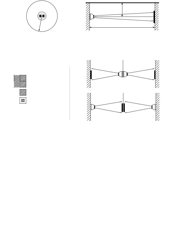
Ensure clear line of sight from Detector to Reflector
Mount on solid surfaces (structural wall or girder)
50— 100m = 4
18— 50m = 1
8—18m = 1
Use Short Range
Mask
•All installations should comply with local regulations
•For detectors approved to UL268 refer to NFPA72 for installation guidance. In such installations, it is advised that the maximum distance of Detector and Reflector from the ceiling must be 10% of the distance between floor and ceiling
•For installations covering less than 18m, the Short Range Mask must be used
•Position beam as high as possible, but with a minimum distance of 0.5m from Detector and Reflector to ceiling.
•Mount Detector and Reflector directly opposite each other
•Do NOT position Detector where personnel or objects can enter the beam path
•Do NOT position 2 Detectors facing each other
•Detector LED indicator must face downward
•Do NOT install the Detector or Reflector in environments where condensation or icing are likely to occur
2

2. Fitting the Product
Clip PCB into base
Insert Detector cable
LED indicator must face downward
3

3. Wiring Diagrams
Wiring two Detectors onto two Zones:
|
|
|
|
|
|
|
EOL |
|
|
|
||
|
To Detector 1 |
|
To Detector 2 |
|
|
|
|
|
|
|||
|
|
|
|
|
|
|
|
|
see |
|
|
|
|
|
|
|
|
|
|
|
|
note 1 |
|
|
|
|
|
|
|
|
|
N/O |
|
COM |
N/C |
N/O |
COM |
N/C |
|
DET 1 |
|
|
DET 2 |
|
1 |
|
2 |
3 |
1 |
2 |
3 |
|
|
|
|
|
|
|
Con C |
|
|
Con D |
|
|
|
|
|
|
|
|
|
|
Fire |
|
|
Fault |
|
|
|
|
|
|
|
|
|
|
|
14V - 36V DC |
||
|
|
Fire |
|
|
Fault |
|
|
|
|
|
Ext |
|
|
|
|
|
|
|
|
|
|
Reset |
|||
|
|
Con A |
|
|
Con B |
|
|
|
|
|
||
1 |
2 |
|
3 |
1 |
2 |
|
3 |
|
|
|
|
|
|
N/O |
COM |
N/C |
N/O |
COM |
|
N/C |
|
|
|
|
|
|
|
|
|
see |
|
|
|
|
|
|
|
|
|
|
|
|
note 1 |
|
|
|
|
|
|
|
|
Zone 1 - |
|
|
EOL |
|
|
|
|
|
|
|
|
|
Zone 1 + |
|
|
|
|
|
|
|
|
|
|
|
|
Ext Reset
Supply +
Supply -
Zone 2 +
Zone 2 -
•Note 1: This component is the fire resistor. Its value is specified by the Fire Control Panel manufacturer. For U.S. installations it is typically a short circuit
•ALWAYS use a separate 2-core cable for each Detector head
•CAUTION: For system monitoring - Do not use looped wire under any terminals. Break wire run to provide monitoring of connections
•Components not supplied:
•End Of Line ('EOL') component - supplied by Fire Control Panel manufacturer
•Fire Resistor
•After installation, check operation of Fire and Fault connection on Fire Panel
•Apply a voltage of 5V to 40V to ‘Ext Reset’ contact for at least 2 seconds to clear a latched fire condition
4

3. Wiring Diagrams (continued)
Relay connections for wiring the two Detectors of one Controller onto one Zone:
EOL
|
|
|
|
N/O |
COM |
N/C |
N/O |
COM |
N/C |
|
|
|
|
1 |
2 |
3 |
1 |
2 |
3 |
|
|
|
|
|
Con C |
Con D |
|
|
|
|
|
|
|
|
|
Fire |
Fault |
|
|
|
Fire |
Fault |
|
|
|
|
|
||
|
Con A |
Con B |
|
|
|
|
|
||
1 |
2 |
3 |
1 |
2 |
3 |
|
|
|
|
N/O |
COM |
N/C |
N/O |
COM |
N/C |
|
|
|
|
see note 1
Zone 1 -
Zone 1 +
For wiring to other types of Fire Control Panel, or to wire multiple Controllers onto one Zone, refer to additional installation instructions supplied with the product
5
 Loading...