

Page 1
Motorised Infrared
Optical Beam Smoke Detector
User Guide
EN
Page 2
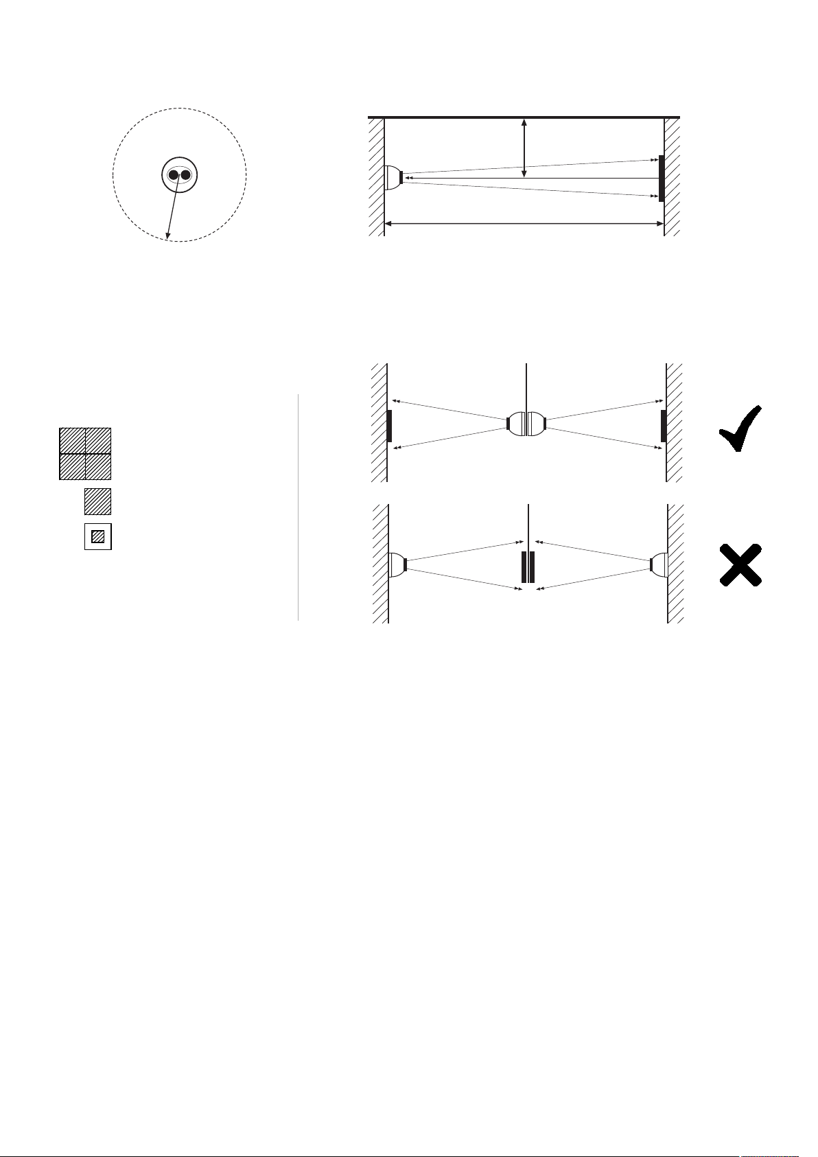
50cm
8-100m
50cm
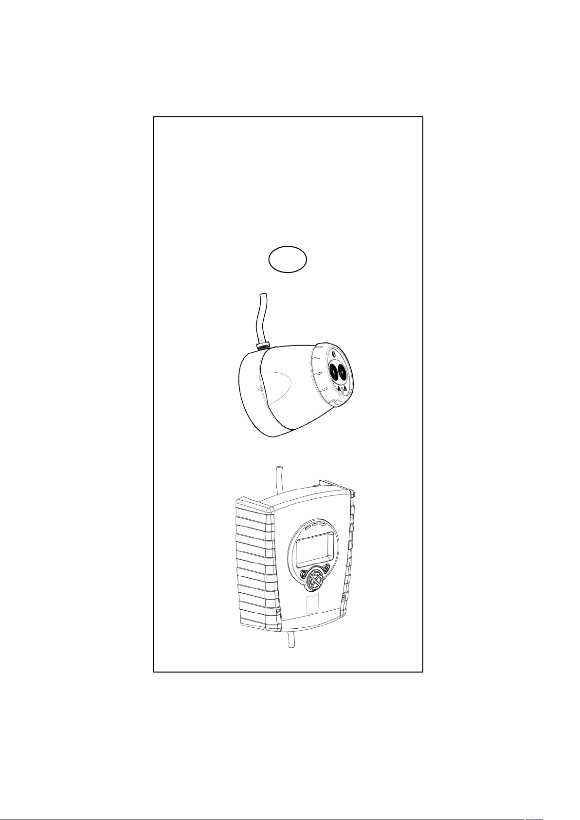
1. General Information
50cm
50cm
8-100m
Ensure clear line of
Mount on solid surfaces (structural wall or girder)
sight from Detector
to Reflector
50—100m = 4
18—50m = 1
8—18m = 1
Use Short Range
Mask
• All installations should comply with local regulations
• For detectors approved to UL268 refer to NFPA72 for installation guidance. In such
installations, it is advised that the maximum distance of Detector and Reflector from the
ceiling must be 10% of the distance between floor and ceiling
• For installations covering less than 18m, the Short Range Mask must be used
• Position beam as high as possible, but with a minimum distance of 0.5m from Detector and
Reflector to ceiling.
• Mount Detector and Reflector directly opposite each other
• Do NOT position Detector where personnel or objects can enter the beam path
• Do NOT position 2 Detectors facing each other
• Detector LED indicator must face downward
• Do NOT install the Detector or Reflector in environments where condensation or icing are
likely to occur
2
Page 3
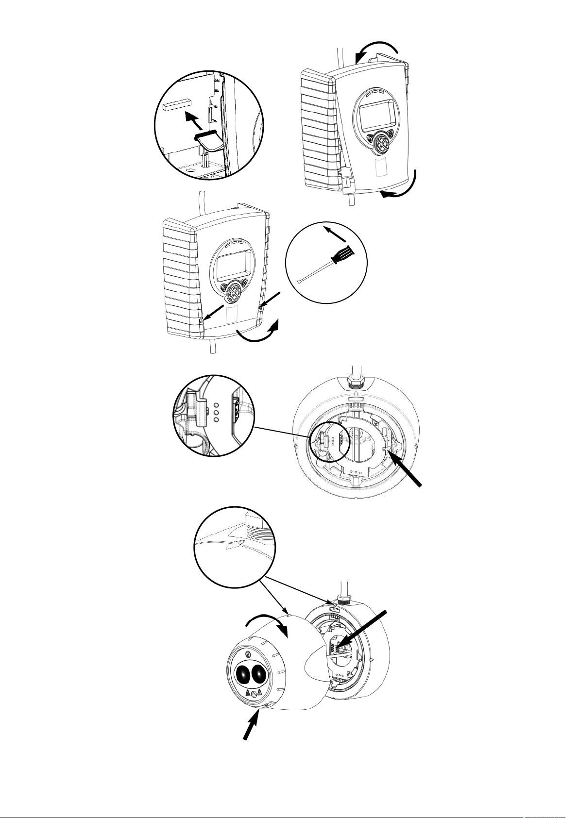
2. Fitting the Product
LED indicator must face downward
Clip PCB into
base
Insert Detector
cable
3
Page 4
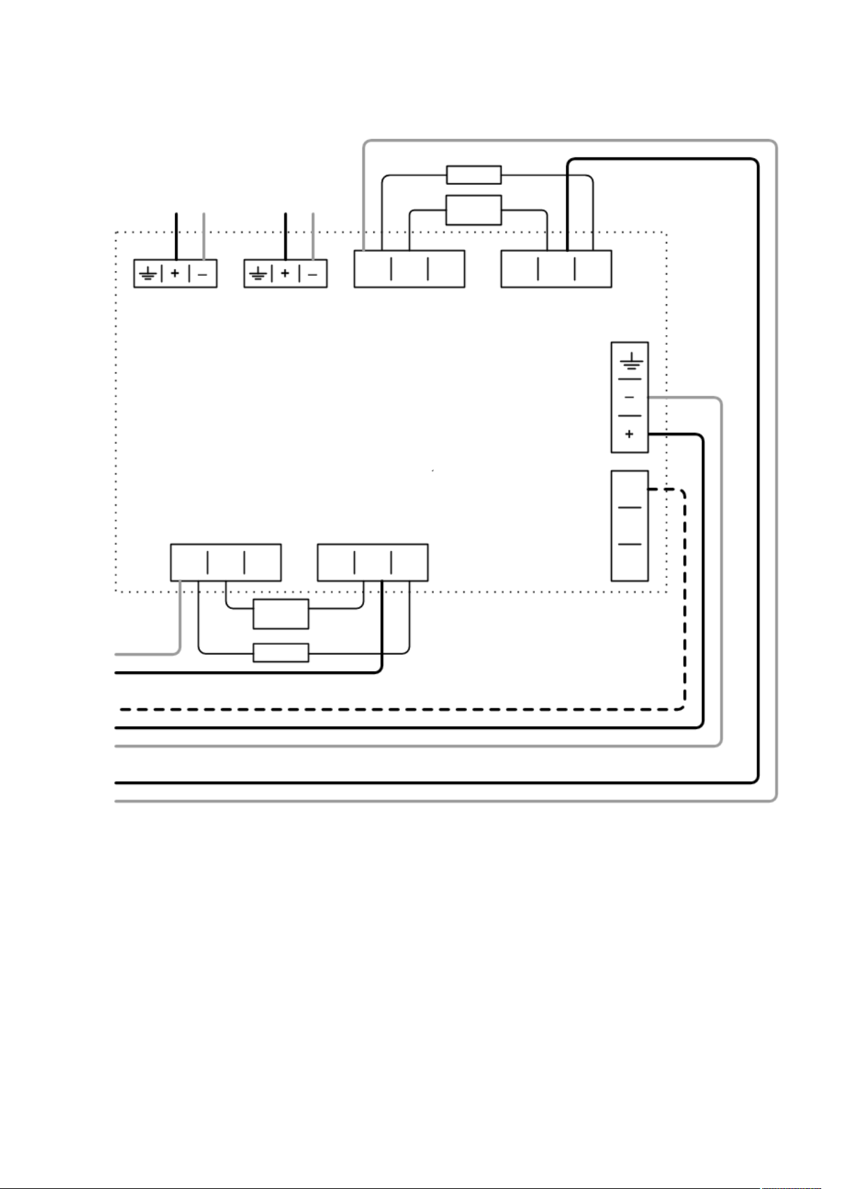
3. Wiring Diagrams
Wiring two Detectors onto two Zones:
To Detector 1 To Detector 2
DET 1 DET 2
Fire
Con A
1 2 3 1 2 3
N/O COM N/C N/O COM N/C
EOL
see
note 1
N/O COM N/C N/O COM N/C
1 2 3
Con C
Fire
Fault
Con B
1 2 3
Con D
Fault
14V - 36V DC
Ext
Reset
see
note 1
Zone 1 Zone 1 +
Ext Reset
Supply +
Supply -
Zone 2 +
Zone 2 -
EOL
• Note 1: This component is the fire resistor. Its value is specified by the Fire Control Panel
manufacturer. For U.S. installations it is typically a short circuit
• ALWAYS use a separate 2-core cable for each Detector head
• CAUTION: For system monitoring - Do not use looped wire under any terminals. Break wire
run to provide monitoring of connections
• Components not supplied:
• End Of Line ('EOL') component - supplied by Fire Control Panel manufacturer
• Fire Resistor
• After installation, check operation of Fire and Fault connection on Fire Panel
• Apply a voltage of 5V to 40V to ‘Ext Reset’ contact for at least 2 seconds to clear a latched
fire condition
4
Page 5

3. Wiring Diagrams (continued)
Relay connections for wiring the two Detectors of one Controller onto one Zone:
EOL
N/O COM N/C N/O COM N/C
1 2 3
Con D
Fault
Zone 1 Zone 1 +
1 2 3
Fire
Con A
1 2 3 1 2 3
N/O COM N/C N/O COM N/C
see
note 1
Fault
Con B
Con C
Fire
For wiring to other types of Fire Control Panel, or to wire multiple Controllers onto one Zone,
refer to additional installation instructions supplied with the product
5
Page 6

4. Apply power
NOTE: One System Controller can be used to control and monitor up to two Detector heads.
The ‘#’ symbol in this guide is used to represent the number of the Detector currently selected
(1 or 2).
5 seconds
5 seconds
5 seconds
• Commissioned system:
• Detectors have been found but the selected Detector is not
aligned:
• Detector is connected but not ‘Found’ (normal on
uncommissioned system):
• Communications fault, or no Detector connected:
6
Page 7

5. Enter Pass Code to Access Engineering Menu
Press for Pass Code screen:
• Default Pass Code: 1 2 3 4
• Change digit
• Move between digits
• Accept
• An incorrect Pass Code will return the display
to the Pass Code entry screen
• Three incorrect attempts will lock access for
three minutes
6. Find Detectors
• ‘Find’ is automatically displayed the first time this process is run. ‘Find’ can also be accessed
in the System Controller settings menu. Find must be performed when adding or removing a
detector to an already ‘Found’ system.
60 seconds
This will be the number
of Detectors found
• Press to enable ‘Found’ Detectors at any point
during 60s countdown
• Any unused Detector channels are switched off
• Press to re-scan if number is incorrect
7
Page 8

7. Select Power Mode
• In ‘Hi A’ mode (default), during
normal operation the system
will take 5.5mA if one Detector
is connected or 8mA if two
Detectors are connected.
During Laser targeting, Auto,
Hand and Home functions, the
system will take 36mA.
• In ‘Lo A’ mode (selected via the
System Controller settings
menu), the system will take
5.5mA or 8mA in ALL modes of
operation. The Detector will
move more slowly during Align,
Laser targeting and Home, so it
is recommended to leave the
system set to ‘Hi A’ if the
current is available.
8. Select Detector
• Select Detector to be accessed
• All Detectors need to be aligned separately
• Steps 9 to12 explain how to align individual Detectors
2
1
9. Select Distance between Detector and Reflector
• Select 8- 50m (default) or 100m
(Set for each Detector)
8
Page 9

10. LASER Targeting
The system will signal Fault while in this mode
The LASER is used to align the Detector with the Reflector. It is an approximate alignment tool
only. After Auto-Align the LASER will not necessarily be pointing on the Reflector
• Use to move the LASER as close to the Reflector as possible
• One press of an arrow key results in one movement of the Detector head
• Press or to turn off the LASER and return to the Settings menu
• Refer to Additional Detector Information for troubleshooting if LASER is not visible
DANGER
LASER RADIATION - AVOID
DIRECT EYE EXPOSURE
POWER OUTPUT < 5mW
CLASS IIIa LASER
Wavelength 630 - 680 nm
11. ‘Auto’ Alignment
• Select ‘Auto’ to automatically align the infrared beam
• Signal Strength will be shown during Alignment
• If the LASER is turned on it will not necessarily be pointing on the Reflector after ‘Auto’ is
run - this is normal
• If ‘Auto’ ends with an error code ‘E- ’, refer to troubleshooting
HiA: 2 minutes
LoA: 25 minutes
9
Page 10

12. ‘Set’ 0/100 (Calibrate)
• When ‘Set’ is displayed press whilst the Reflector is still uncovered
• When ‘S-00’ is displayed, cover the Reflector with a non- reflective material and leave
covered, then press
• When ‘S-01’ is displayed, uncover the Reflector and leave uncovered, then press
• Repeat Steps 8 to 12 for any other Detectors found during the ‘Find’ process
13. System is Aligned
• Green LED on Detector will flash every 10 seconds, and Signal Strength should be between
99% and 101%
• Default values: 35% Fire Threshold, 10 second delay to Fire and Fault, Non-Latching mode
10
Page 11

14. Manual Fire and Fault Tests
After installation or cleaning, it is recommended that a manual Fire and Fault test is
performed:
Fire Test: Cover the Reflector slowly so that it takes longer than 5 seconds to cover. The
System Controller will signal Fire to the Fire Control Panel after the delay to fire has expired
(10s default)
Fault Test: Cover the Reflector completely within 2 seconds. The System Controller will signal
Fault back to the Fire Control Panel after the delay to fault has expired (10s default)
15. Remote Fire Test
It is possible to perform a Fire Test from the System Controller, to test the wiring to the Fire
Control Panel
NOTE: The Remote Fire Test is acceptable for Fire Authority Acceptance and Routine
Maintenance per UL268-5
Detector Fire LED Test
Detector will signal Fire,
System Controller will stay
Normal.
Press to exit
without performing the test
Relay/Controller Wiring Test
System Controller signals
‘Fire’ to Fire Control Panel
Press or to
exit
11
Page 12

16. Fire Threshold
This setting is the threshold at which the Detector will detect a fire
Default factory setting=35%
(Set for each Detector)
• Sensitivity can be adjusted in 1% steps by pressing up or down keys
• Press to accept setting
UL268 Fire Threshold Ranges:
Distance between
Detector and Reflector
8—10m (26.2—32.8ft) 10—18%
10—15m (32.8—49.2ft) 15—25%
15—22m (49.2—72.2ft) 15—35%
22—40m (72.2—131.2ft) 25—50%
40—60m (131.2—196.8ft) 35—50%
60—100m (196.8—328.1ft) 50%
EN Approved Sensitivity Ranges:
Complies with EN54-12 for sensitivity levels between 25% and 35% with a maximum delay to
fire of 20 seconds
Fire Threshold
Range
12
Page 13

17. Fire/Fault Delay
These settings are the delays that the System Controller uses before signalling a FIRE or
FAULT condition respectively to the Fire Control Panel. Default factory setting=10 seconds
(Set for each Detector)
elay 2 (Fault)
Delay 1 (Fire)
D
18. Latching/Non-Latching Mode
In Latching Mode the system will stay in Fire condition after the fire clears. In Non-Latching
Mode the system will automatically return to normal condition after the fire clears
(Set for each Detector)
Non-Latching
Latching
Use to move between icons in the
Detector Menu, until the graph and bell icons
are shown
To clear a latched fire, apply 5-40V to the External Reset terminal, enter the passcode, or
power cycle for 20s
13
Page 14

19. Cleaning the System
The system will automatically compensate for dust build-up by changing the Compensation
Level.
However, it is recommended that the Detector lenses and the Reflector are cleaned
periodically with a soft lint-free cloth.
If the Compensation Level for a particular Detector remains above 130 for several days, this
indicates that cleaning should take place on that Detector.
The system should be isolated from the Fire Control Panel before cleaning takes place.
After cleaning, verify that the system is operating normally:
If the Signal Strength is between 92% and 108%
- leave the system to compensate back to 100% (this should take no more than 12 hours)
If the Signal Strength is above 108%
- reduce Compensation Level until Signal Strength is 92—108%, and wait for system to
compensate back to 100%
If the Signal Strength is below 92%
- perform LASER Targeting, Auto-Align, and Set.
How to change Compensation Level:
14
Page 15

20. Troubleshooting
E-00
E-01
E-02
E-03
AIM not
recognised
Detector
Communications
Error
Detector is
connected but not
‘Found’
Compensation
limit reached
• Refer to manufacturer
for technical assistance
• Check wiring between
System Controller and
Detector (Voltage to
Detector should be
11—13V)
• Follow ‘Find’ process
and align if necessary
• Clean and realign
system
Compensation
E-08
Level Not Zero
during ‘SET’
Signal Strength
Out of Range
E-09
when ‘SET’
selected
Reflector Not
E-10
Found during
Auto-Align
Auto-Align
E-11
Failed
• Re-align Detector using AutoAlign
• Ensure Reflector uncovered
when ‘SET’ selected
• Ensure clear line of sight from
Detector to Reflector for a radius
of 0.5m
• Ensure correct distance has
been selected
• Ensure correct Reflectors have
been used
• Realign Detector
• Ensure clear line of sight from
Detector to Reflector for a radius
of 0.5m
• Ensure correct distance has
been selected
• Ensure correct Reflectors have
been used
• Realign Detector
• Ensure clear line of sight from
Detector to Reflector for a radius
of 0.5m
• Ensure correct distance has
been selected
• Ensure correct Reflectors have
been used
• Realign Detector
E-04
E-05
E-06
E-07
Detector missed
too many readings
Detector is not
aligned
Rapid Obscuration
Fault
Signal Too High
Fault
• Check voltage to
Controller.
• Check voltage to
Detector is >11V
• Follow alignment
procedure
• Ensure clear line of
sight from Detector to
Reflector
• Ensure clear line of
sight from Detector to
Reflector
• Ensure there is no
strong light on Detector
Cannot Zero
During ‘S-00’ in
‘Set’
E-12
Signal did not
decrease when
‘S-00’ selected
No Signal
During ‘S-01’ in
‘Set’
E-13
Signal did not
increase when
‘S-01’ selected
‘Centre’ Stage
of Alignment
Failed
Detector has
E-14
aligned on
something other
than the
Reflector
Power too low
E-21
fault
• Ensure Reflector was
completely covered with a nonreflective material
• Re-align Detector using AutoAlign
• Ensure Reflector was uncovered
when ‘S-01’ was selected
• Ensure clear line of sight from
Detector to Reflector for a radius
of 0.5m
• Check power supply to
Controller
15
Page 16

21. Technical Specifications
Parameter Value
Operating Voltage 14—36V DC
Operating Current – Normal Operation
(including fire or fault activated)
Operating Current – Alignment modes - HiA
Alignment modes - LoA
Fire Threshold Range
Delay to Fire 2—30 s
Delay to Fault 2—30 s
Operating Distance between Detector and Reflector 8—100 m
Maximum angular misalignment of Detector ± 0.3 Deg
Maximum angular misalignment of Reflector ± 5 Deg
Maximum angular movement of Detector head ± 3.5 Deg
Optical wavelength 850 nm
Rapid Obscuration Fault threshold 87%
Operating Temperature (UL Approved) 0—+37.8 Deg C
5.5mA - 1 Detector
8mA - 2 Detectors
36mA
5.5mA / 8mA
0.45—3.98 dB
10—60%
Operating Temperature (EN54-12 Approved) -10—+55 Deg C
Operating Temperature (FM Approved) -20—+55 Deg C
Storage temperature -40—+85 Deg C
Relative Humidity (non condensing) 93%
IP Rating IP54
Relay Contact Rating
Maximum Cable Length (Controller to Detector) 100 m
Cable Gauge
Housing Flammability rating UL94 V0
UL File S3417
CPD Certificate Number 0832-CPD-0565
Dimensions
System Controller, including base 202 (8.0) 230 (9.1) 81 (3.2) 1.0 (2.2)
Width,
mm (in)
Height,
mm (in)
VFCO, 2A@30VDC
Resistive
24—14 AWG
0.5—1.6 mm
Depth,
mm (in)
Weight,
kg (lb)
Detector, including 'easy fit' base 135 (5.3) 135 (5.3) 135 (5.3) 0.5 (1.1)
Reflector (Single) 100 (3.9) 100 (3.9) 10 (0.4) 0.1 (0.2)
Document Number: 0044-033-04-EN
16
 Loading...