

Page 1

FIRERAY 2000 EExd
Hazardous Area Smoke Detector
Installation Guide
KEY FEATURES
Flameproof Receiver and Transmitter
Standard Fireray Controller Unit
High Coverage - up to 15002m per system
Low Cost
Beam Range 10 metres to 100 metres
12 Volts dc to 24 Volts dc operation
Selectable Alarm Thresholds
Low Current Consumption
Manual or Automatic Fire Alarm Reset
Automatic Fault Alarm Reset
Ground Level Electronics
Extremely Rugged
Easy installation
Low maintenance
DESCRIPTION
The FIRERAY 2000 EExd SMOKE DETECTOR SYSTEM is designed primarily to protect EExd, IIB
hazardous areas.
It consists of a standard Fireray 2000 Controller/Analyser, combined with highly rugged flameproof
Transmitter and Receiver heads.
The Transmitter and Receiver Heads are designed to be mounted within the protected hazardous area,
whilst the Analyser is housed outside it. Using the Standard Analyser unit in this way allows a
significant cost reduction when compared to a system utilising flameproof enclosures for all component
parts. The maximum lateral beam coverage is 15m per Fireray System installed.
Once installed, the Transmitter Head projects a modulated Infra-Red Beam across the protected area, to
the Receiver head mounted opposite. The received signal strength is monitored and analysed in the
Ground Level Controller. Should the beam strength fall below the preset threshold for more than 8 -10
seconds, a Fire Alarm is signalled to the Control Equipment. The analyser also incorporates monitoring
for cable breaks or loss of function at the Transmitter or Receiver. If the signal strength is reduced
suddenly (<5 seconds) by greater than 93% a Fault Alarm is indicated to the Control equipment. The
Fire and Fault Alarm outputs are provided via two sets of Voltage-Free change-over relay contacts.
The Fire Alarm Relay may be set for latched or auto-reset operation as desired. The Fault Alarm is
designed to auto-reset once the signal is returned to serviceable limits.
The system may be used with ‘intelligent’ or ‘non-intelligent’ systems. Due to the very low current
consumption, back-up battery life is extended and the system may be powered from alarm loop supplies
in most cases.
PARTS LIST
1 x Transmitter Head (With Clear Lens)
1 x Receiver Head (With Dark Lens)
1 x Controller/Analyser Unit
1 x Adjustable Head Mounting Bracket
1 x Bag of Bracket Fixings
Page 1 of 12
APPLICATIONS
Ex II 2 G Environments
Refineries
Mills
Munitions Factories
Munitions Stores
Flammable Liquid Stores
Flammable Gas Stores
Flammable Powder Stores
Industrial Plants
Power Stations
Warehouses
Applications requiring highly rugged
detector heads
1 x Test Filter
1 x Installation Guide (This document)
2 x Allen keys (5mm & 10mm)
Page 2

STATEMENT OF INTENDED USE
This system is intended for use as a Smoke Detector only, in EExd IIB, or lower grade areas. It must
not be used in areas with a greater hazard rating. It must be installed and tested by approved, competent
personnel, in accordance with all regulatory and local codes of practise. No liability shall be accepted
for installations not conforming to this requirement.
The equipment is covered by certificate number Sira03ATEX1504, and the following instructions
apply.
1. The equipment may be used with flammable gases and vapours with apparatus group II and with
temperature class T6. in the ambient temperature range -20°C to +55°C.
2. The equipment is only certified for use in ambient temperatures in the range -20°C to +55°C and
should not be used outside this range.
3. Installation should be carried out by suitably trained personnel in accordance with the applicable
code of practice e.g. EN 60079-14:1997.
4. Inspection of this equipment shall be carried out by suitably trained personnel in accordance with
the applicable code of practice e.g. EN 60079-17.
5. The equipment does not have any user-serviceable parts and must be returned to the manufacturer
for servicing or repair.
6. This Installation Guide contains the system Principle of Operation; system Specification;
Installation Precautions; Installation Setting Up and Testing; Installation diagrams.
7. On the Transmitter and Receiver, the allowable gap is 0.2mm maximum between the Housing and
the Cover,
8. The certification of this equipment relies upon SM87 Enclosure Component (typically Aluminium
Alloy or Stainless Steel) Certificate No. Baseefa03ATEX0345U/1 from MEDC Ltd.
9. If the equipment is likely to come into contact with aggressive substances, then it is the
responsibility of the user to take suitable precautions that prevent it from being adversely affected,
thus ensuring that the type of protection provided by the equipment is not compromised.
Aggressive substances : e.g. acidic liquids or gases that may attack metals, or
solvents that may affect polymeric materials.
Suitable precautions : e.g. regular checks as part of routine inspections, or
establishing from the material’s data sheets that it is
resistant to specific chemicals.
NOTE : If in doubt, contact the supplier.
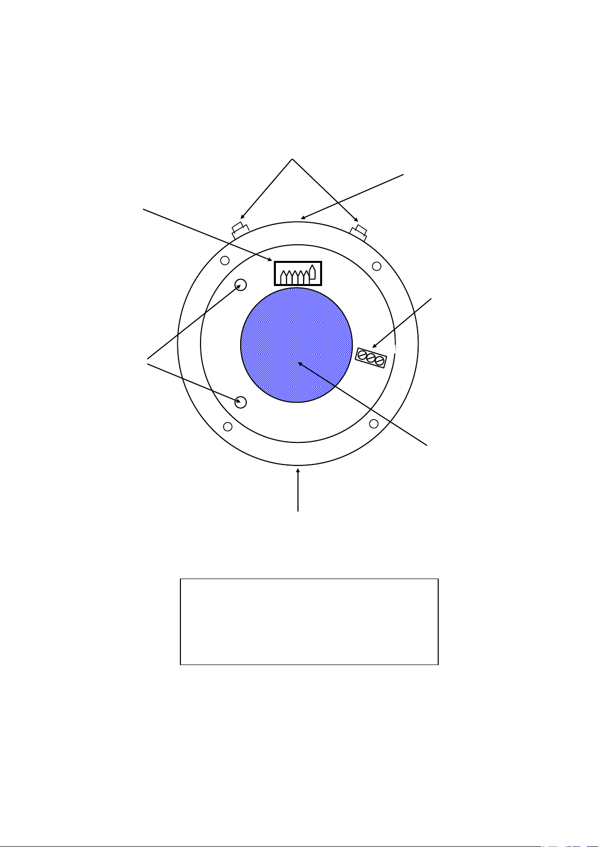
10. Label details :
Page 2 of 12
Page 3

WARNING
The area into which the Fireray parts are to be fitted must be made safe before attempting any work
on the system. It must also be checked thoroughly prior/during/after commissioning, to ensure it
cannot compromise the safety of the area in which it is fitted. Note that only the Transmitter and
Receiver parts may be installed in the hazardous area, NOT the Controller Unit.
If the flamepath of the enclosure is damaged in any way, the unit must be returned to the
manufacturer and a new unit purchased.
PRINCIPLE OF OPERATION
General
The Fireray system operates by passing an infra-red beam between a Transmitter and Receiver, through
the protected area. The received signal strength will be attenuated if smoke is present in the beam. The
beam strength is measured continuously and, should any attenuation be present which exceeds presets
thresholds, fire or fault alarms are generated as appropriate. Each installed Fireray can cover an area 7.5
metres either side of the beam, giving a maximum coverage of up to 15002m with a 100m beam path
length.
Transmitter and Receiver Units
A modulated Infra-Red light beam is projected from the Tx (Transmitter ) via it’s optical system. The
projected beam has a circular footprint, with a useable spread of approx 3m @ 100m range. The Rx
(Receiver) has a corresponding filtered optical system which collects and focuses the beam onto a
photo-detector. During installation, the Rx has a maximum beam acceptance angle of up to 5
(dependant on gain and threshold settings). The wide Tx beam, in conjunction with the large Rx
acceptance angle simplifies alignment and gives good tolerance to beam mis-alignments after
installation.
Controller Unit And Alarm Thresholds
The signal received at the Rx is amplified and filtered to reject sunlight and other unwanted optical
noise such as may be caused by ambient lighting,. The signal is then passed to the Controller Unit,
where it undergoes further filtering and validity checking, before finally being analysed for signal
strength. The signal is then compared to a reference level (determined by the user’s threshold setting),
and should the signal be reduced below the set threshold, the FIRE ALARM relay will be activated
within approx 12 seconds. Three user selectable threshold setting are available **. Note that only one
threshold switch must be closed to select the required threshold. A red lamp on the Controller Unit
front panel also indicates a FIRE ALARM condition.
Controller Unit -Fault Thresholds
If the signal is reduced suddenly by more than 93% in 8 to 10 seconds, perhaps due to total beam
blockage, a cable break, or the Tx or Rx becoming unserviceable, the controller interprets this as a fault
situation. Loss of power to any of the system parts will also cause a fault signal to be generated. In any
of these events, the controller will activate the FAULT ALARM relay continuously. The system will
return to normal operation immediately, once the correct signals are restored, except in the event of a
power loss to the controller, in which case normal operation is resumed after 50 seconds from
restoration of power. A yellow lamp (LED4) in the Controller Unit also indicates when the system is in
a FAULT or RESET condition.
Controller Unit - Compensation (AGC) Operation And Action At Compensation Limit
The Controller Unit also incorporates an AGC (Automatic Gain Control) system , which monitors very
slow changes in the received signal due to contamination of the optical system (EG: build up of dust on
the lenses) and any changes due to system ageing. If the signal is reduced by more than approx 11%, the
AGC system is activated. Then if the signal is still low after 1.5 hours, a 7% increase is made to the
system gain, to bring the signal strength back into the nominal range. Additionally, should the signal
strength increase, perhaps due to improved alignment following building movement, the system can
reduce its gain in 7% steps. From an initial nominal setting, up to 11 increasing and 3 decreasing
correction steps are possible.
Page 3 of 12
Page 4

Two possible actions are selectable, once the system has exhausted all compensation steps, as follows:-
Leave the COMP switch in the Controller unit OPEN for BS5839 installations (UK). This
setting allows generation of a FIRE ALARM after reaching the compensation limit, even
though a FAULT ALARM will be active. This is the only time Fire and Fault indications can
occur together.
Close the COMP switch if it is required that FIRE ALARM generation is inhibited once a
FAULT ALARM has occurred, due to reaching compensation limit.
Controller Unit - Relay Outputs
The Controller Unit has two sets of outputs for Fire and Fault indication, in the form of voltage free
single pole changeover relay contacts. The FIRE relay may be set to give either latching or non-latching
operation, determined by a switch (ALARM LATCH) on the Controller pcb. With the switch closed,
latching operation is selected.
Controller Unit - Signal Strength Metering
A ‘Metering ‘ output is also provided, to assist with installation. This gives a dc voltage which is
proportional to the received signal strength and can be monitored using a voltmeter.
Controller Unit - System Resetting
The system can be reset in any of three ways, as follows :-
Using the RESET switch in the Controller Unit (Normally only used during installation).
By taking the External Reset input low (to system 0V) for at least 5mS.
By de-powering the system for 1 second, then re-powering.
Following a reset the system takes 50 seconds to self-calibrate. During this time the Fireray adjusts it’s
100% signal reference level and so must have a clear unobstructed beam. No tests should be carried out
until this initialisation period has elapsed.
Notes On Resetting Using The Internal RESET Switch
Note that for correct operation, the internal RESET switch must not be set to OFF whilst either of
the HIGH or LOW signal lamps in the Controller Unit are illuminated. The gain must be set
correctly to extinguish both lamps first. If this is not done the system AGC is locked and will not
operate. (This does not apply to the other two reset methods).
SUMMARY OF SYSTEM CONDITIONS :-
Possible Causes of FAULT Alarms
Controller Unit RESET switch in ON position.
Controller Unit EXTERNAL RESET input active ( at 0V)
No power to Controller unit
No Power to Tx unit
Beam obscuration >93% for >5 seconds (for whatever reason)
Tx or Controller power cable break.
Receiver Signal cable break.
AGC at limit of compensation.
Rx/Tx Mis-alignment causing low signal strength
System unable to initialise following reset, due to inability to calibrate correctly (perhaps caused by
interference or testing of the beam before expiry of the 50 second calibration period.
High or Low signal when Controller Unit’s RESET switch set to OFF (AGC locked out).
Possible Causes Of FIRE Alarms
In normal use, beam strength reduced by more than the set threshold (Smoke in beam).
Page 4 of 12
Page 5

During installation, no threshold switch set at the Controller Unit (One switch only must be set).
Possible Causes Of FIRE And FAULT Alarms Together
AGC at limit of compensation, COMP switch OPEN (UK installations only) and beam strength
reduced by more than the set threshold.
PRECAUTIONS WHEN INSTALLING THE SYSTEM
Always ensure that the hazardous area into which the system will be installed is safe to work in, and that
neither you nor the installation will compromise the safety of that area.
Ensure that all mandatory and local regulations, regarding both fire alarm systems and EExd, IIB
applications, are adhered to.
Choose solid, stable surfaces on which to mount the Receiver and Transmitter.
If one of the mounting surfaces for the Transmitter or Receiver is likely to be susceptible to movement,
always mount the Transmitter on the more stable surface. The Receiver is less affected by misalignments.
The beam should be positioned approx 30cm to 60cm below the ceiling, to avoid smoke layering or
masking effects.
Take precautions to position the beam such that it cannot be blocked during the normal course of
operations in the building.
Avoid mounting near or over heaters systems etc. Heat haze may cause obscuration and high levels of
beam ‘noise’.
If possible, avoid areas subject to thermal ‘shock’, such as near external loading bay doors etc. If
condensation forms on the lenses, this will be seen as an obscuration.
Avoid high intensity lighting near the receiver lens and avoid angling the Receiver directly at the sun.
The system incorporates circuitry to minimise effects due to high levels of ambient light (>15000 Lux),
but over heating of internal parts may occur with very strong sources, due to the focused beam within
the Receiver.
If possible, avoid bunching the system cables with factory power or other cabling.
To achieve maximum EMI rejection, use screened cables for the system wiring, properly terminated at
metal glands (Do not use screen pigtails). MICC cable is recommended.
Use the correct EExd approved cable gland types for all system parts in the hazardous area.
Cables must be suitable for a minimum temperature of 101°C.
SETTING UP AND ALIGNING
The Transmitter and Receiver heads must be positioned on stable, solid facing surfaces, such as
parallel walls, approx 0.3m to 0.6m below the area ceiling (See application notes near the end of this
guide). The surfaces must be parallel, vertically and horizontally within approx 20 degrees, although a
greater positioning range is possible (up to 40 degrees off line-of-sight) if the Receiver is also fitted it
with an Adjustable Mounting Bracket. This is available as an optional extra. If only small adjustments
are required, the Receiver line-of-sight may be adjusted by fitting spacer washers to its wall fixing
Page 5 of 12
Page 6

screws, between the Receiver Case and the mounting surface. (Some applications may require
fabrication of angled mounting brackets etc, in order to cope with awkward wall positions etc. These
are not supplied).
Install all required cabling to the defined positions for each system part. (See wiring diagram on
following page, for a typical installation). Ensure compliance with all regulatory and local requirements
for Hazardous Areas and Fire Alarm Systems. Approved screened cables and approved EExd glands
and termination methods must be used. Glands at the Controller, Rx and Tx must be metal EExd types.
The Cable screens or jackets must be terminated properly at the glands, with a 360 termination. Screen
Pigtails must not be used.
Mount the Receiver first, such that it faces, and has un-obstructed line of sight with the expected final
Transmitter position. Remove the Receiver housing top (using 5mm Allen key provided). Connect the
system cabling to the 3 way terminal block on the internal pcb. It is recommended that the External
Earth point be used on the Tx and Rx housings, to minimise wiring lengths. This must be taken to the
nearest suitable building Earth point. Alternatively, the housing’s Internal Earth stud may be connected,
via an additional cable core and connected back at the Control Unit Earth. (see wiring diagram on the
following page for connections and earthing regimes). Check the connections and tighten the cable
glands, then refit the housing top, taking care to position the ‘O’ ring seal correctly, just below the
flange. Tighten the 4 securing screws firmly. For safety reasons, and to give the best EMI rejection,
do not omit any of the Earth connections.
Fit the Transmitter head in a position which aligns as closely as possible with the Receiver line of sight,
making use of the adjustment bracket provided. A 12mm AF spanner/wrench is required for the
adjustment bolts. Remove the Transmitter housing top (using 5mm Allen key provided) and set the
Range Switch to the correct or next higher setting, to match the expected operating range. Use a biro tip
to set the switches. The switches are ‘ON’ when moved outward, and ‘OFF’ when moved inward,
toward the housing centre. Note that only one setting must be selected ‘ON’. Connect the system
cabling to the 3 way terminal block on the internal pcb and Earth the unit housing in the same manner
as used for the Rx (see wiring diagram on the following page for connections and earthing regimes).
Check the connections and tighten the cable glands, then refit the housing top, taking care to position
the ‘O’ ring seal correctly, just below the flange. Tighten the 4 securing screws firmly. For safety
reasons, and to give the best EMI rejection, do not omit any of the Earth connections.
Install and wire the Controller unit in it’s defined position, outside the hazardous area. Set the unit’s
Alarm threshold to 25%, 35% or 50%. Only close one switch position, for the desired threshold. Set
the ‘ALARM LATCH’ switch as required. Switch Closed = latching Fire Alarm operation. For UK
installations, leave the ‘COMP’ switch open (Sets AGC operation at compensation limit - See
functional descriptions on page 2).
Check all wiring then apply power to all parts of the system.
At the Controller Unit, Set the Reset Switch to ‘ON’, and the Gain Control knob to approx midway.
Connect a length of two core bell wire or similar to the Metering terminals in the Control Unit. Run this
temporarily to the Transmitter position and connect a dc voltmeter to the ends. Set the voltmeter to
read up to 10Vdc or ‘autorange’.
Whilst observing the meter reading, adjust the Transmitter-to-Receiver alignment to achieve the highest
reading possible. A reading of at least 4.1Vdc is required for correct function (Note : <=2.7Vdc = no
signal). On completion, lock the transmitter adjustment bracket and all mountings securely, checking
the alignment on the meter whilst doing so. Remove the temporary meter wiring on completion.
Return to the Controller Unit and observe the Green lamps either side of the Gain Control. Adjust the
Gain Control such that the two lamps both extinguish completely.
Set the Controller unit’s Reset Switch to ‘OFF’, observe that the yellow FAULT lamp extinguishes,
then wait at least 50 seconds while the system calibrates. After 50 seconds, check that the FAULT lamp
is still extinguished. The system is now armed and active.
Page 6 of 12
Page 7

TESTING THE SYSTEM
Following installation, test the system as follows :-
First ensure that the system is running and has been allowed time to calibrate (50 seconds after powerup or reset).
Fire Alarm
Place the striped end of the test filter over the Receiver lens.
A Fire Alarm shall be indicated in approx 10 to 12 seconds.
Fault Alarm
Place a complete blockage (example: a hand) over the Receiver lens. Ensure that the lens is
fully covered.
A Fault Alarm shall be indicated in approx 4 to 6 seconds.
Page 7 of 12
Page 8

Rx
HIGH
LOW
RELAY WIRING,
CONNECT AS REQUIRED
TO INDICATING
EQUIPMENT
TEST/RESET
SW5
+V Rx
SIGNAL Rx
0V Rx
TEST
EXTERNAL
RESET
-
+
0V
+VE
OPTIONAL
TRANSMITTER P.S.U
(OR USE CONTROLLER
AND RECEIVER P.S.U)
12Vdc TO 24Vdc
-
N/O
100MA (T)
0V
+VE
CONTROLLER AND
RECEIVER P.S.U
ALARM
N/C
CO
N/O
N/C
CO
F
A
U
L
A
L
A
R
SIGNAL LEVEL
+
COMP
25%
35%
50%
EExd
GLAND
EExd
GLAND
METAL
GLAND
METAL
GLAND
METAL
GLAND
METAL
GLAND
OPTIONAL REMOTE
RESET WIRING
(SEE TEXT)
CLOSE TO
RESET
HAZARDOUS
AREA
NON-HAZARDOUS
AREA
METAL EExd
GLAND
Tx
METAL EExd
GLAND
Rx EXTERNAL CASE
EARTH (SEE TEXT)
Tx EXTERNAL
CASE EARTH (SEE
SUPPLY
12Vdc
TO
FAULT
LED1
LED2
LED4
FUSE
CONTROLLER UNIT/PCB
Typical installation shown (See text).
Do not omit any Earth connections.
MICC cable recommended for all cabling.
Approved, EExd glands must be used at the Rx
and Tx, and at the interface partitioning the
hazardous and non-hazardous areas.
1
0
0
m
m
a
x
Page 8 of 12
Page 9
1020406080
100
TRANSMITTER REQUIRES 2 CORE SCREENED WIRING
TO SUITABLE POWER SUPPLY, PLUS ENCLOSURE
EARTH BONDING.
THE ENCLOSURE EARTH BOND MAY BE CONNECTED
TO THE INTERNAL OR EXTERNAL EARTH TERMINALS
AND MUST NOT BE OMITTED.
-VE
+VE
Do not route wiring within the
50mm circular central area, to avoid
obscuring optical components
Internal Earth stud
will be found in one
of these two positions
External Earth terminal will be
found in one of these two positions
User wiring terminals.
Wire only to the -VE and +VE
terminals. (Middle ‘SIG’ terminal
not used on Transmitter units)
Field wiring must be correctly
terminated with insulation stripped
no more than 1mm from connector
terminal.
User wiring to enter here, via suitable
EExd IIB or IIC approved gland.
VIEW INSIDE TRANSMITTER UNIT WITH TOP WINDOW SECTION REMOVED
SHOWING TERMINALS AND SETTINGS ETC
note: some components not shown for clarity
REF:
Range switch shown set to 100m.
Only one switch position to be
ON at a time
Do not use this hole for cable entry
(EExd blanking plug fitted at factory)
Page 9 of 12
Page 10
-VE
+VE
Do not route wiring within the
50mm circular central area, to avoid
obscuring optical components
Internal Earth stud
will be found in one
of these two positions
External Earth terminal will be
found in one of these two positions
User wiring to enter here, via suitable
EExd IIB or IIC approved gland.
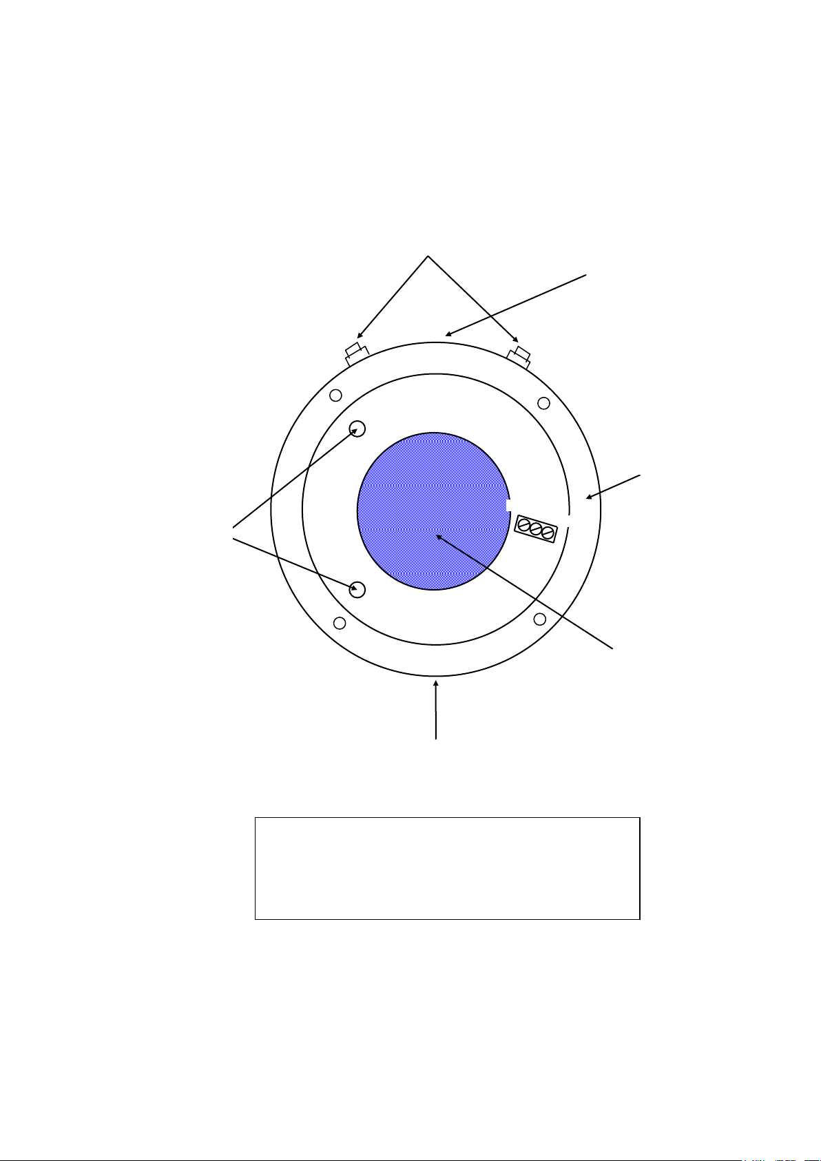
VIEW INSIDE RECEIVER UNIT WITH TOP WINDOW SECTION REMOVED
SHOWING TERMINALS AND SETTINGS ETC
note: some components not shown for clarity
SIG
RECEIVER REQUIRES 3 CORE SCREENED WIRING TO
CONTROLLER UNIT, PLUS ENCLOSURE EARTH BONDING.
THE ENCLOSURE EARTH BOND MAY BE CONNECTED TO
THE INTERNAL OR EXTERNAL EARTH TERMINALS
AND MUST NOT BE OMITTED.
User wiring terminals.
Connect back to Controller
Unit via suitable EExd
cabling. Field wiring must
be correctly terminated with
insulation stripped no more
than 1mm from connector
terminal.
Do not use this hole for cable entry
(EExd blanking plug fitted at
factory)
Page 10 of 12
Page 11

This page left intentionally blank
Page 11 of 12
Page 12
FIRERAY 2000 EExd - SYSTEM
SYSTEM TYPE
Transmitter (TX)
Rugged for EExd IIB areas - IP67
Receiver (RX)
Rugged for EExd IIB areas - IP67
Controller (CU)
Designed to be sited outside the hazardous
area. Rugged for light industrial and
domestic use - IP50
CERTIFICATION
SIRA03ATEX1504
CONFORMS WITH
EExd General
requirements)
BS EN 50014 : 1998
EExd enclosures
BS EN 50018 : 2000
Fire Alarm Systems
BS 5839 : Pt 5 : 1988
Emc Immunity
BS EN 61000-6-2:1999
Emc Emissions
BS EN 61000-6-4:2001
Alarm Systems - EMC
BS EN 50130-4 1996
ATEX Directive
94/9/EC
TEMPERATURE
Range
-20C to +55C
THRESHOLDS
Alarm
25%, 35% or 50%**, switch selectable
(1.25db, 1.87db or 3.01db**)
** For full compliance with BS5839 Pt.5,
use 25% and 35% thresholds. 50%
threshold is normally recommended for retro
mode.
Fault
>=93% (11.55db), fixed
DETECTION TIMES
Fire
10 seconds (min)
Fault
5 seconds (min)
SYSTEM RANGE
Minimum
10m
Maximum
100m
TRANSMITTER
Type
Pulsed, Focused Infra-Red beam
Beam Half-Angle
1 approx
Spectrum
Nominally 880Nm (Near Infra-Red)
Max IR O/P (mean)
6.4mW/Sr at IR LED
Max IR O/P (peak)
800mW/Sr at IR LED
Misalignment angle
@25% and (@ 50%) threshold settings
During installation
+/-1 (+/-1) for a measurable signal
After installation
+/-0.5 (+/-0.75) (After perfect alignment)
Connections
2 wire, power only required - no connection
to other system parts necessary
RECEIVER
Misalignment angle
@25% and (@ 50%) threshold settings
During installation
+/-4 (+/-5) for a measurable signal
After installation
+/-3 (+/-4) (After perfect alignment)
Connections
3 wire, connected to Controller Unit only
SUPPLY VOLTAGES
(At each detector component)
Tx (nominal)
+12Vdc to +24Vdc
Tx (min/max)
+11.5Vdc to +28Vdc
Control/Rx (nominal)
+12Vdc to +24Vdc
Control/Rx (min/max)
+11.5Vdc to +28Vdc
Rx
N/A, Supplied from Control Unit
SUPPLY CURRENT
Control/Rx (Normal)
7.5mA @ all ranges
Control/Rx (Alarm)
13.5mA @ all ranges
Tx
1.6mA @10m to 5.6mA max @100m
SUPPLY RIPPLE
Tx
0.5V p-p min, sine, 50-100Hz @11.5Vdc
Immunity increases with higher supply
voltage
Control/Rx
0.5V p-p min, sine, 50-100Hz @11.5Vdc
Immunity increases with higher supply
voltage
SYSTEM RESET
Internal
Via slider switch in controller unit
External (1)
Remote Reset input - Ground for >5mS
External (2)
Power break for 1 second then re-power
INITIALISATION
TIME
Following reset
50 seconds
SYSTEM OUTPUTS
Fire Alarm
Voltage-Free SPCO contacts, switch
selectable for latching or auto-reset
operation.
Fault Alarm
Voltage-Free SPCO contacts, auto-resetting
operation
Contact ratings
1.0A @ 24Vdc (resistive)
0.3A @ 24Vdc (Inductive)
0.5A @ 120Vac (resistive)
0.2A @ 120Vac(inductive)
Meter Output
DC output proportional to signal strength,
for alignment and maintenance check
purposes
Meter Range
No signal
Low signal
Normal signal
High signal
2.7Vdc to 6Vdc approx
2.7Vdc
>2.7Vdc to <4.1Vdc
4.25Vdc +/-0.15Vdc
> 4.4Vdc
COMPENSATION
(AGC)
Function
Detects and corrects for Rx/Tx lens
contamination, or minor gain errors after
installation or reset.
Update Period
Every 1.5 hours
Correction step
Approx 7% per step
Correction Range
Approx -28% to +77% (% with respect to
initial setting)
SYSTEM CABLING
Max Cable Run
100m to any system part
Cable Type
Screened (MICC recommended)
Max Capacitance
100pF/m
SIZES
Controller
215mm x 265mm x 88mm
Heads
120mm x 125mm x 125mm
Brackets
172mm x 124mm x 56mm
WEIGHTS
Controller
1060 grammes
Tx
2140 grammes
Rx
2165 grammes
Brackets
1530 grammes
FINISH
Controller
White Powder Coat, to RAL 9010
Heads
Red Powder Coat to RAL 2002
Brackets
Red Powder Coat to RAL 2002
SPECIFICATION
Document Number: 23989.00.01
Page 12 of 12
 Loading...