

Page 1

FIRERAY
FEATURES
2000
• Range 10 – 100 Metres
Optical Beam Smoke Detector
• 11.5Vdc to 28 Vdc
operating voltage
• Selectable alarm
thresholds
•
Low current
consumption
•
Ground level electronics
• Manual or automatic
reset
•
Automatic contamination
compensation
Fire Fighting Enterprises Ltd.
Approved by VdS No. : G 297058
to EN54 Part 12
Fireray 2000 Installation Guide 22318.00.R 25.08.05
Page 2

System Description
The Fireray 2000 is a linear beam smoke detection system capable of protecting an open indoor area of up to
1500 square metres.
The System comprises a Transmitter which projects a modulated infrared beam over an area to a Receiver,
which then for wards a signal to a Control Unit f or analysis. T he System ca n detect smok e particles obsc uring
the beam path. When obscured for a predefined length of time the Control Unit will generate an alarm.
Smoke Detection
When smoke i s presen t in th e beam pat h the s ignal rec eived by the Recei ver is re duced rela tive to the densit y
of the smoke. If the density of the smoke reduces the signal below a preset threshold for a period of 10 seconds
an alarm relay is activated.
There are 3 selectable threshold levels available, 25%, 35%, and 50%. (25% being the most sensitive).
Auto Reset
The alarm relay is configurable and can be either latching or non-latching.
If non-latching is selected the alarm relay will reset 5 seconds after the smoke has cleared.
If latching is selected the alarm relay will remain set until either a power down reset is performed, or the
Controller Unit receives an external reset.
Automatic Gain Control
The Control Unit supports an Automatic Gain Control (AGC) circuit. Long term degradation of signal strength by
the build up of dirt on optical surfaces will not generate an alarm because of compensation provided by the
AGC circuit. This operates by comparing the received signal against a standard over a predefined time interval
which is nominally 1.5 hours, if the signal strength deviates by more than 7% over this time span the Receiver
gain is automatically adjusted to compensate.
Fault Detection
The Control Unit is capable of detecting failures within the System. In the event of a System failure being
detected the fault relay is activated.
System failures will be caused by:
• The TEST/RESET switch in the Control Unit set to the ON position
• Total loss of power or a supply reduction below the specified minimum to the Control Unit.
• The System is unable to settle during the power on AGC stabilisation period.
• The System AGC circuits have reached the limit of compensation.
• The signal has been reduced by more than 93% for approximately 10 seconds.
• The beam path is completely blocked.
A Transmitter failure.
•
• Loss of power to the Transmitter.
• A Receiver failure.
• Misalignmen t of the Transmitter and Receiver resulting in a signal loss of greater than 93%
Fireray 2000 Installation Guide 22318.00.R 25.08.05
2
Page 3
Detector Positioning
Φ
Υ
It is important that the Fireray 2000 Detector is positioned correctly to minimise the detection time.
Experiments have shown that smoke from a fire does not rise directly upwards, but fans out or mushrooms due
to air currents and heat layering effects. The time to signal a fire condition depends on the location of the
Detector within the premises, the volume of smoke produced, construction of the roof, and ventilation
arrangements.
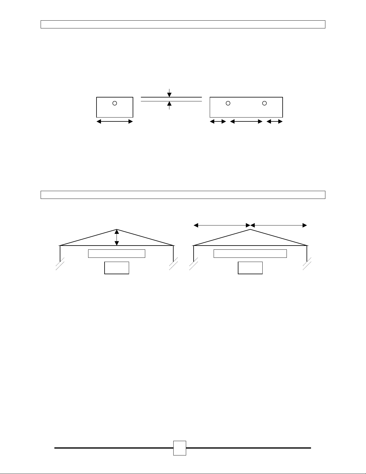
The maximum distance either side of the beam axis is found to be typically 7.5 metres for satisfactory detection
under flat ceilings.
Single Beam
Multiple Beams
0.3m ↔ 0.6m
15 m
MAX
(0.5m ↔ 7.5m)
MAX
15 m
MAX
(0.5m ↔ 7.5m)
MAX
Smoke layerin g, where smoke does not reach the ceiling l evel due to layers of static hot air is over come by
mounting the Detector at the recommended height below the ceiling of between 0.3 and 0.6 metres, bringing
the infrared beam below the heat layer and into the smoke layer.
However in all i nstallations the national fi re standards for that particu lar country mus t be consulted. If there is
any doubt on the correct mounting height, positioning may be determined by smoke tests.
Detector Positioning In Apex Of Sloping Ceiling
A ceiling is defined as sloping if the distance from the top of the apex to the intersection of the ceiling and
adjacent wall is greater than 0.6 metres (See fig. 1).
Υ
Χ
Slope if Χ ≥ 0.6 Metres
= Pitch angle
=
+
Fig 1 Fig 2
When a Detect or is posit ioned in the apex of a ceiling (See f ig. 2). The lat eral beam dist ance covered (Υ) can
be increased in relation to the angle of pitch (Φ).
For Example:
If the pitch angle is 20 degrees the lateral coverage can be increased from 7.5 metres either side of the beam
(Υ) to:
Υ = 7.5 + (7.5 x 20/100) metres
Υ = 9 metres
Therefore with a roof pitch of 20 degrees the lateral coverage can be increased from 7.5 metres either side of
the beam to 9 metres either side of the beam, but only for the beam positioned in the apex. All other
calculations remain the same.
This formula can be applied to pitch angles up to and including 25 degrees. Therefore the maximum increase in
lateral coverage can be:
Υ = 7.5 + (7.5 x 25/100) metres
Υ = 9.375 metres
Pitch angles over 25 degrees must use the maximum lateral figure of 9.375 metres either side of the beam.
Fireray 2000 Installation Guide 22318.00.R 25.08.05
3
Page 4

Installation
Pre-installation at Ground Level
Confirm that all parts have been supplied as listed in the parts list. See page 8.
Control Unit
1. There are 20mm knockout holes on all side faces for fixing of cable glands. Four 7mm fixing holes are
located on the rear surface of the box, which are to be used to locate the Control Unit to the building
structure.
2. Select the required alarm threshold (See fig. 7 for switch configuration settings). The factory default setting
is 35% this should be adequate for most environments, if the Detector is to be installed into an exceptionally
dirty environment change the threshold to 50%.
3. Select latching or auto reset for the alarm relay. The factory defaul t se tti ng is auto reset, change this option
if required (Se e fig. 7 for switch configura tion settings).
4. Select the AGC compensation setting; to comply with BS5839 leave the switch open, this is the default
factory setting. At the last AGC stage the Fireray will signal a fault, but in the event of any further signal loss
reducing the signal to the selected sensitivity level will result in a fire alarm (See fig. 7 for switch
configuration settings). If the switch is closed, at the last AGC stage the Fireray will signal a fault but the fire
relay will be inhibited.
5. Mount the Control Unit at gr ound level to a flat surface, preferably a wall, using the fixing holes provided.
Ease of access is essential for system commissioning and “follow on” service calls.
6. Terminate the field wiring (See figs. 5 & 6 for wi ring instructions).
Transmitter and Receiver
1. Confirm that the Transmitter Power is set to maximum (See fig 3).
2. Locate positions for both Transmitter and Receiver using the positioning methods described earlier.
3. Ensure there is a clear line between the Transmitter and the Receiver. No more than 3 metres of the beams
path should be within 500mm of any wall or partition. Make sure that no single object is within 300mm of the
centre of the beam.
4. Fix the right angle brackets provided to a solid structure, which is not effected by thermal and or mechanical
movement.
X Do not fix to plaster board or cladded walls as these surfaces do and will move W
4. Mount th e Transmitter and Recei ver heads using the ‘U’ br ackets provided onto t he right angle brackets
(See fig 3 for details).
5. Wi re the Receiver to the Control U nit using not l ess than 5 metr es and no more than 100 metr es of good
quality 3 core screened cabl e, make sure al l junction box es used are met al and terminat ed with the cable
screen. At the Control Unit terminate the screen at the entry gland (See fig 6 for details)
Do not terminate the screen inside the Control Unit.
Alignment
Receiver
1. Mechanically align the Receiver as accurately as possible (by eye) to the Transmitter.
2. A pply power to the Control Unit and check the voltage is within the operating parameters of 11.5 – 28 Volts.
Transmitter
1. Mechanically align the Transmitter as accurately as possible (by eye) to the Receiver.
2. Wire the Transmitter to a power supply (See fig 6 for details).
3. Apply power to the Transmitter and check the voltage is within the operating parameters of 11.5 – 28 Volts.
Fireray 2000 Installation Guide 22318.00.R 25.08.05
4
Page 5

Alignment Method ‘A’ Using Fireray 2000 Alignment Tool
1. Connect the Fireray 2000 alignment tool (optional extra – contact sales for details) to the Control Unit.
2. Position the Alignment Tool so that the LED’s are visible from the Transmitter
3. On the Control Unit PCB set the RESET/TEST switch to ON, and adjust the signal level potentiometer to 12
‘o’clock
4. Adjust the Transmitter orientation whilst observing the LED’s on the Alignment Tool.
5. If the green LED is steady and moving the Transmitter in any direction causes the green LED to flash, the
beam is aligned. Leave the Transmitter in the steady green LED position (go to 8).
6. If moving the Transmitter in any direction causes the red LED to flash, move the Transmitter in that
direction to obtain the red flashing LED (go to 7).
7. If the red LED flashes reduce the power of the Transmitter by removing the cap on the side of the
Transmitter (See fig 3) and using a small screwdriver turn the potentiometer clockwise until the red LED
stops flashing and the green LED stays steady (go to 5).
8. Secure the Transmitter by tightening both the screws in the bracket and recheck the Alignment Tool LED.
9. Continue to Final Settings After Alignment.
Alignment Method ‘B’ Using Voltmeter
1. Connect a voltmeter to the Test Meter terminal and ground on the Control Unit PCB.
2. On the Control Unit PCB set the RESET/TEST switch to ON, and adjust the signal level potentiometer to 12
‘o’clock
3. Adjust the Transmitter orientation whilst observing the reading on the voltmeter.
4. If a voltage of 4.8 ±0.1 volts is observed and moving the Transmitter in any direction causes the voltage to
drop, the beam is aligned. Leave the Transmitter in the 4.8 ±0.1 volts output position (go to 7).
5. If moving t he Transmit ter in any di rection ca uses the v oltage to in crease, m ove transm itter in t hat directi on
to obtain the highe s t v oltage (go to 6).
6. If a voltage of 4.9 to 5.1 volts is observed, reduce the power of the Transmitter by removing the cap on the
side of the Transmitter (See fig 3) and using a small screwdriver turn the potentiometer clockwise until the
voltmeter reading is between 4.8 ±0.1 volts (go to 4).
7. Secure the Transmitter by tightening both the screws in the bracket and recheck the voltage.
8. Continue to Final Settings After Alignment.
Final Settings After Alignment
1. At the Control Unit adjust the signal level potentiometer slowly anticlockwise until the signal HIGH LED just
extinguishes.
2. Confirm that the output at the Test Meter terminal is 4.2 ±0.1 volts.
3. Disconnect the voltmeter and or the alignment tool wires from the Test Meter terminals.
4. Confirm that both signal HIGH and signal LOW LED’S are both OFF.
5. Move the RESET/TEST switch to the OFF position and confirm the fault LED extinguishes.
6. Wait 45 seconds and confirm the fault LED is still extinguished.
Fig 3. Transmit t e r Power
Adjust Potentiometer
Fireray 2000 Installation Guide 22318.00.R 25.08.05
5
Page 6

A
A
A
Alarm Test
1. Taking note of the threshold selected during installation (default 35%).
2. Select obscuration mark on filter to correspond with the Detector alarm threshold (see fig. 4).
3. Place the filter over the Receiver just past the correct obscuration value determined by the threshold
selected. For example if a threshold of 35% has been selected position the filter just past the 35%
obscuration value on the filter (see fig 4 below).
4. The Control Unit will indicate a fire within 10 seconds by activating the RED LED on the Control Unit door
and operating the fire relay.
Reset After Alarm Test
1. Remove the filter from the front of the Receiver, the Control Unit will reset after approximately 4 seconds if
the alarm latch option is configured as auto reset (default setting – switch open).
2. If the latching alarm option has been selected (switched closed) the Control Unit can be reset by either:
• Switching the TEST/RESET switch to ON, then OFF.
• Disconnect the power to the Control Unit for more than 1 second.
• By shorting the external reset terminal on the Control Unit PCB to the negative terminal for more than 1
second.
Fig 4
Í Obscuration value
Receiver Optics
lign filter for correct obscuration/threshold setting
Fault Test
The fault relay and the fault LED operate if the beam is totally blocked for approximately 10 seconds.
Removing the obstruction will automatically reset the beam after approximately 4 seconds.
Typical Single Zone Wiring
LARM
N/O
N/C
COM
larm Resistor
FAULT
N/O
N/C
COM
End of Line Component
N.B. Alarm resistor and
End of Line Com ponent
are not supplied.
Please contact Fire
Panel Manufacturer for
correct values.
+
Earth
-
+VE (12-24 Vdc)
Earth
-VE (0V Return)
Fig 5
Fireray 2000 Installation Guide 22318.00.R 25.08.05
6
Page 7

Rx
SIGNAL LEVEL ADJUSTMENT
TEST/RESET
SWITCH
Tx
-
+
ALARM LATCH
AGC COMPENSATION
ALARM
THRESHOLD
25%
35%
50%
N/O
N/C
COM
N/O
N/C
COM
FUSE
100MA
+
-
M
R
A
L
A
T
L
U
A
F
Fig 6
Fireray 2000 Installation Guide 22318.00.R 25.08.05
7
Page 8

Technical Specifications
Data
Operating Temperature -20°C to +55°C
Operating Voltage 11.5 to 28 Volts DC
Transmitter Current < 1.6 – 5.6mA
Control Unit (includes Receiver) Quiescent Current < 8.5mA
Control Unit (includes Receiver) Alarm Current < 16.5mA
Control Unit (includes Receiver) Fault Current
Operating Range (distance between Transmitter and Receiver) 10 to 100 metres
Receiver toler an c e t o be am mi salignment ± 4°
Transmitte r to le ran c e to beam misalignmen t ± 1°
Fire alarm thresholds 1.25dB (25%), 1.87dB (35%), 3dB (50%)
Optical wavelength 880 nm (Infra red)
Control Unit max dimensions 215mm x 265mm x 88mm
Transmitter and Receiver max dimensions (inc. brackets ) 83mm x 115mm x 135mm
Control Unit weight 1060 gms
Transmitter and Receiver weight (inc. brack ets) 650 gms
Relay Contacts 2A 30 Volts DC resistive
Fireray 2000 Selectable Op tions
SWITCH OPEN CLOSED
ALARM LATCH Fire relay will automatically reset § Fire relay will not auto reset (latch)
COMP For BS5839 part 5 leave open. §
At the last AGC stage the Fireray will signal a fault,
but in the event of any further signal los s reducing
the signal to the selected threshold level, a fire alarm
will be signalled
25% 25% Alarm sensitivity selected
35% 35% Alarm sensitivity selected §
50% 50% Alarm sensitivity selected
NOTE: Select ONE Alarm sensitivity level only.
Application Notes
For full compliance with BS5839 part 5, use the 25% and 35% thresholds. The 50% threshold is only
recommended for hostile environments.
Service Notes
Control Unit contains ESD sensitive devices; appropriate care must be taken when handling internal
components.
Parts List
1 Transmitter (clear lens ).
1 Receiver (dark lens).
1 Control Unit.
2 Right angle brackets.
4 Bolts and washers.
1 Test Filter.
Fig 7
16.5mA
<
At the last AGC stage the Fireray
will signal a fault, the fire relay will
be inhibited
Factory Default Settings.
§
FIRE FIGHTING ENTERPRISES LIMITED
9 Hunting Gate, Wilbury Way, Hitchin
Hertfordshire SG4 0TJ England
Tel: +44 (0) 845 4024242 Fax: +44 (0) 845 4024201 Email: sales@ffeuk.com
www.ffeuk.com
Fireray 2000 Installation Guide 22318.00.R 25.08.05
8
 Loading...