

Page 1

WARNING:
BEFORE USING THIS FIREARM,
READ THROUGH THESE WARNINGS
AND INSTRUCTIONS CAREFULLY
AND THOROUGHLY.
THIS MANUAL SHOULD ALWAYS ACCOMPANY
THIS PISTOL AND BE TRANSFERRED WITH IT
UPON CHANGES OF OWNER OR USER.
PXT Single-Action Series Pistols
SAFETY AND
INSTRUCTION
MANUAL
Para
©2004 Para-Ordnance Mfg., Inc.
Page 2

THIS MANUAL APPLIES TO PARA-ORDNANCE
PXT SINGLE-ACTION P-SERIES & S-SERIES
PISTOLS WITH 5- AND 4.
FIREARMS ARE CLASSIFIED AS DANGEROUS
WEAPONS. THEREFORE THIS PRODUCT IS
POTENTIALLY LETHAL.
FAILURE TO READ, UNDERSTAND AND FOLLOW
ANY OF THESE WARNINGS AND INSTRUCTIONS MAY
RESULT IN INJURY, DEATH OR
DAMAGE OF PROPERTY.
25-INCH BARRELS
FIREARMS SAFETY –
ACCIDENT PREVENTION
YOUR RESPONSIBILITY
WHEN PRESSING THE TRIGGER, YOU MUST
EXPECT THE GUN TO FIRE AND YOU MUST
TAKE FULL RESPONSIBILITY FOR FIRING IT
ALWAYS TREAT A FIREARM
AS IF IT WERE LOADED
WARNING
CHILDREN ARE ATTRACTED TO AND CAN OPERATE FIREARMS
THAT CAN CAUSE SEVERE INJURIES OR DEATH. PREVENT
CHILD ACCESS BY ALWAYS KEEPING GUNS LOCKED AWAY AND
UNLOADED WHEN NOT IN USE. IF YOU KEEP A LOADED FIREARM
WHERE A CHILD OBTAINS AND IMPROPERLY USES IT, YOU MAY
A LOS NINOS LOS ATRAEN LAS ARMAS DE FUEGO Y LAS PUEDEN
HACER FUNCIONAR ELLOS PUEDEN CAUSARSES LESIONES
GRAVES Y LA MUERTE. EVITE QUE LOS NINOS TENGAN ACCESO
A LAS ARMAS DE FUEGO GUARDANDOLAS SIEMPRE CON LLAVE
Y DESCARGADAS CUANDO NO LAS ESTE UTILIZANDO, SI USTED
TIENE UNA ARMA DE FUEGO CARGADA EN UN LUGAR EN QUE
UN NINO TIENE ACCESO A ELLA Y LA USA INDEBIDAMENTE, LE
PUEDEN DAR UNA MULTA O ENVIARLO A LA CARCEL.
WARNING: DO NOT MAKE ANY ATTEMPTS TO PRACTICE LOADING,
UNLOADING, ETC. WITH LIVE AMMUNITION UNLESS YOU HAVE
FULLY UNDERSTOOD THIS MANUAL AND ARE CERTAIN ABOUT
THE PROPER HANDLING AND OPERATION OF THIS PRODUCT.
WHERE IN DOUBT ABOUT YOUR ABILITY TO HANDLE OR USE
THIS HANDGUN SAFELY, SEEK SUPERVISED INSTRUCTION RUN BY
A LOCAL GUN CLUB, GUN DEALER, OR POLICE DEPARTMENT.
BE FINED OR SENT TO PRISON.
ADVERTENCIA
THE BASIC PRINCIPLES OF HANDLING AND
OPERATION OF THIS FIREARM MUST BE FULLY
UNDERSTOOD AND FOLLOWED EXACTLY.
THIS MANUAL IS PROVIDED TO ASSIST YOU
IN THE PROPER USE AND MAINTENANCE OF
YOUR PARA-ORDNANCE PISTOL. IF YOU HAVE
ANY FURTHER QUESTIONS, PLEASE CONTACT
US DIRECTLY.
MANUALS ARE AVAILABLE
FREE FROM THE FACTORY:
®
Para
980 TAPSCOTT ROAD
SCARBOROUGH, ONTARIO M1X 1C3
(416) 297-7855 • FAX: (416) 297-1289
www.paraord.com
Page 3
CONTENTS
MAIN FEATURES ...............................................................................
FIREARM SAFETY INSTRUCTIONS ........................................
FEATURES
TECHNICAL DATA & AMMO INFO ........................................
SAFETY FEATURES
SLIDE LOCK SAFETY ...................................................................
GRIP SAFETY .................................................................................
PASSIVE SAFETIES .......................................................................
FUNCTION
MALFUNCTIONS ..........................................................................
LOADING ........................................................................................
UNLOADING ..................................................................................
FIRING ..............................................................................................20
GRIP ...................................................................................................
MAINTENANCE
DISASSEMBLY ................................................................................
REASSEMBLY .................................................................................
POWER EXTRACTOR .................................................................. 32
CLEANING PISTOL .....................................................................
CLEANING HIGH-CAPACITY MAGAZINE ........................
DISASSEMBLY, CLEANING AND REASSEMBLY
10-ROUND PARA-ORDNANCE MAGAZINE .......... 36
OF
TRANSPORTATION & STORAGE ..........................................
WARRANTY INFORMATION .....................................................
SERVICE & REPAIR .........................................................................
LIMITS & LIABILITY ......................................................................
SPARE PARTS ......................................................................................
PARTS ILLUSTRATION .................................................................
PARTS LIST ..........................................................................................
Page
1
3
8
9
11
12
13
14
19
21
23
28
33
34
39
40
41
42
43
44
45
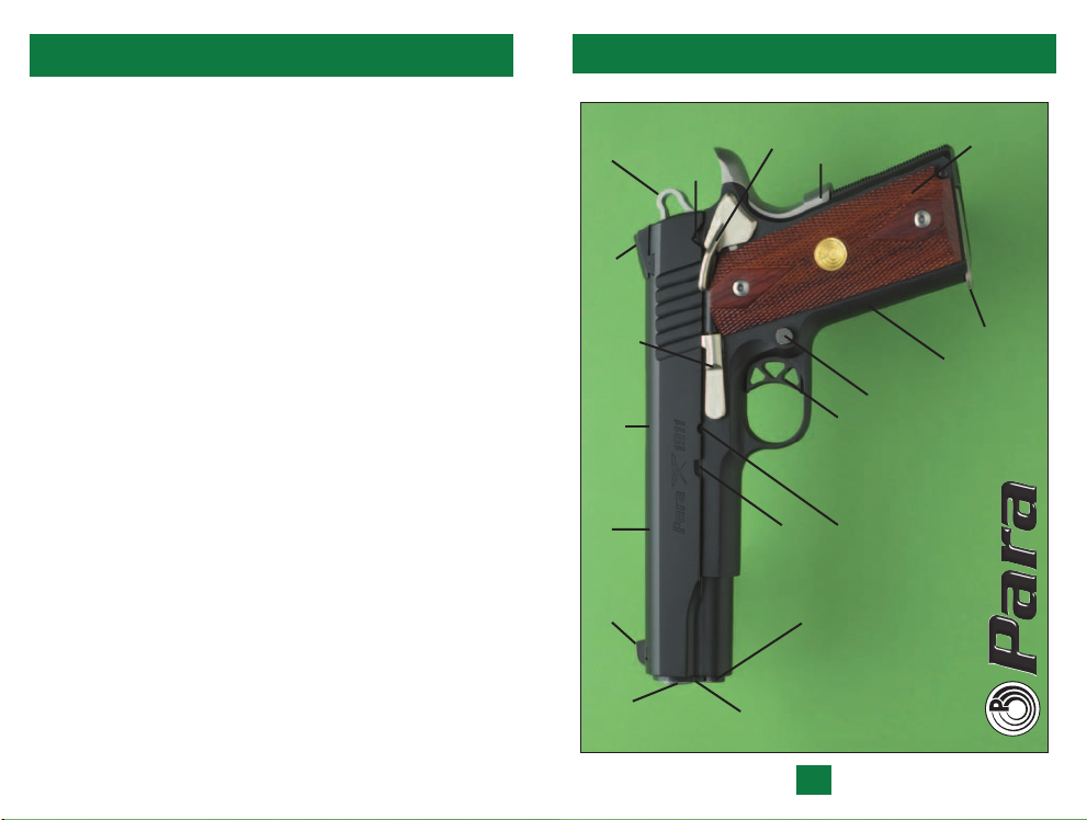
MAIN FEATURES -
SLIDE
LOCK
SAFETY
HAMMER
REAR SIGHT
SLIDE STOP
EJECTION PORT
(OTHER SIDE)
SLIDE
FRONT SIGHT
BARREL
NOTCH
PXT Single-Action Models
GRIP
SAFETY
SAFETY
SLIDE LOCK
MAGAZINE
CATCH
TRIGGER
NOTCH
DISASSEMBLY
SLIDE STOP
NOTCH
SPRING PLUG
RECOIL
BUSHING
BARREL
PXT 1911 SSP
1
STOCK
MAGAZINE
RECEIVER
Single Action, Single-Stack
Page 4
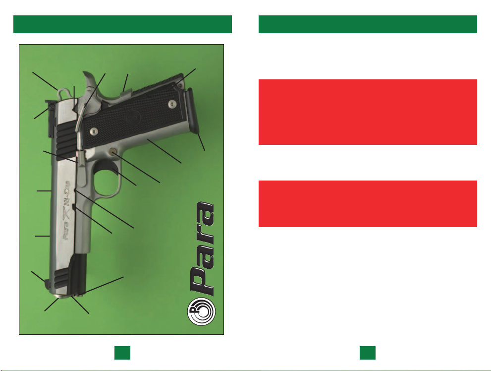
MAIN FEATURES -
PXT Single-Action Limited
FIREARMS SAFETY INSTRUCTIONS
HAMMER
REAR SIGHT
SLIDE STOP
EJECTION PORT
(OTHER SIDE)
SLIDE
FRONT SIGHT
BARREL
SAFETY
SLIDE LOCK
NOTCH
BARREL
SAFETY
SLIDE LOCK
SLIDE STOP
BUSHING
GRIP
NOTCH
SPRING PLUG
RECOIL
SAFETY
TRIGGER
NOTCH
DISASSEMBLY
STOCK
RECEIVER
MAGAZINE
CATCH
Single Action, Hi-Cap
S14•45 Limited
MAGAZINE
DO NOT USE ANY FIREARM WITHOUT HAVING A FULL
AND COMPLETE UNDERSTANDING OF ITS PARTICULAR
MECHANICAL AND HANDLING CHARACTERISTICS.
FOR YOUR SAFETY AND THE SAFETY
OF OTHERS YOU MUST ENSURE YOUR
COMPLETE AND CLEAR UNDERSTANDING
OF THIS MANUAL AND YOU MUST FOLLOW ITS
SAFETY INSTRUCTIONS EXACTLY.
NEVER ALLOW ANYONE TO USE THIS FIREARM WITHOUT
HAVING THAT PERSON READ THIS MANUAL FIRST.
IMPROPER HANDLING OF YOUR PISTOL
CAN RESULT IN INJURY, DEATH
OR PROPERTY DAMAGE.
CAUTIONS:
1.
ALWAYS TREAT EVERY FIREARM AS IF IT WERE LOADED.
2. NEVER – EVER – POINT ANY GUN, LOADED OR
UNLOADED, AT ANYTHING YOU DO NOT INTEND
TO SHOOT.
3. ALWAYS KEEP YOUR FINGER AWAY FROM THE TRIGGER,
OUTSIDE THE TRIGGER GUARD, UNTIL YOU ARE AIMING
AT A TARGET AND READY TO SHOOT.
2 3
Page 5

4. ALWAYS BE SURE OF YOUR BACKSTOP, WHAT LIES
BEYOND YOUR TARGET, AND THE SAFETY OF
BYSTANDERS BEFORE YOU CONSIDER SHOOTING
YOUR PISTOL. THE BACKSTOP MUST BE ADEQUATE
TO STOP AND CONTAIN BULLETS. OTHERWISE, A
BULLET IS CAPABLE OF TRAVELING THROUGH OR
PAST YOUR TARGET FOR A DISTANCE OF UP TO 1
MILES. DO NOT SHOOT IF YOU ARE UNCERTAIN
ABOUT WHAT LIES BEYOND YOUR TARGET.
5. ALWAYS MAKE SURE YOUR PISTOL IS UNLOADED AND
THE SLIDE IS LATCHED OPEN BEFORE HANDING IT TO
ANOTHER PERSON OR LAYING IT DOWN.
6. ALWAYS MAKE SURE THAT YOUR PISTOL HAS NOT
BEEN IN ANY WAY DAMAGED AS THE RESULT OF IT
HAVING BEEN DROPPED OR ANY OTHER INCIDENT
OR CIRCUMSTANCE, INCLUDING CORROSION, THAT
MAY HAVE POSSIBLY CAUSED DAMAGE TO SOME
PARTS OF THE MECHANISM.
7. ALWAYS HAVE A COMPETENT GUNSMITH INSPECT
YOUR PISTOL SO AS TO ENSURE ITS PROPER FUNCTION.
REMEMBER, ONLY WEAPONS IN PERFECT WORKING
ORDER CAN BE SAFE WEAPONS.
8. NEVER LEAVE A PISTOL COCKED AND READY TO FIRE.
1
/2
ALWAYS USE YOUR HANDGUN SAFELY AND
WISELY. PROTECT YOURSELF AND THOSE
AROUND YOU BY TAKING THE PROPER AND
NECESSARY PRECAUTIONS PRIOR TO FIRING
YOUR PISTOL. REMEMBER, UNSAFE PRACTICES
CAN BE THE CAUSE OF INJURY, DEATH,
OR PROPERTY DAMAGE.
9. NEVER LEAVE A LOADED PISTOL UNATTENDED.
10. ALWAYS MAKE SURE THAT ANY OTHER SHOOTERS
OR BYSTANDERS ARE WELL CLEAR OF YOU WHEN
PREPARING TO SHOOT YOUR PISTOL. EJECTED
CARTRIDGES CAN CAUSE INJURY TO ANYONE
STANDING IN THEIR PATH. NEVER OBSTRUCT THE
EJECTION PORT ON YOUR PISTOL BY PLACING
YOUR FINGERS IN FRONT OF IT.
11. ALWAYS WEAR ADEQUATE SHOOTING GLASSES
AND ENCOURAGE OTHERS TO DO THE SAME.
UNPROTECTED EYES MAY BE INJURED BY POWDER
GAS, CARBON RESIDUE, LUBRICANT, METALLIC
PARTICLES OR SIMILAR DEBRIS THAT CAN DAMAGE
EYES AND EVEN CAUSE BLINDNESS.
12. ALWAYS WEAR ADEQUATE EAR PROTECTION AND MAKE
SURE THAT OTHERS IN YOUR VICINITY DO THE SAME.
REPEATED EXPOSURE TO SHOOTING NOISE CAN LEAD
TO CUMULATIVE, PERMANENT HEARING LOSS.
13. ALWAYS CARRY YOUR PISTOL EMPTY WITH THE SLIDE
LATCHED OPEN UNTIL PREPARING TO FIRE.
ALWAYS EMPLOY SAFE HANDLING,
LOADING, AND SHOOTING METHODS.
REMEMBER A LOADED FIREARM HAS
THE POTENTIAL TO KILL. INTELLIGENTLY
14. NEVER CONSUME ALCOHOL OR TAKE DRUGS PRIOR
HANDLED IT CAN BE USED SAFELY.
TO SHOOTING. IF UNDER MEDICATION, SEEK A
DOCTOR’S ADVICE TO BE SURE THAT YOU ARE FIT
AND ABLE TO HANDLE A GUN SAFELY.
4
5
Page 6

15. NEVER SHOOT AT A FLAT SURFACE OF WATER OR AT
ANY HARD SURFACE IN ORDER TO AVOID HAZARDOUS
RICOCHETS THAT CAN CAUSE INJURY, DEATH, OR
PROPERTY DAMAGE.
ALWAYS USE AMMUNITION THAT COMPLIES
WITH THE INDUSTRY PERFORMANCE
STANDARD AS ESTABLISHED BY THE
SPORTING ARMS AND AMMUNITION
MANUFACTURER’S INSTITUTE (SAAMI).
TO DO OTHERWISE MAY RESULT IN INJURY,
DEATH, OR DAMAGE TO PROPERTY.
20. USE OF EXTRA HIGH-PRESSURE AMMUNITION MAY CAUSE
RELIABILITY PROBLEMS. AS WITH ANY HANDGUN,
PROLONGED USE OF EXTRA HIGH PRESSURE AMMUNITION
MAY SHORTEN THE SERVICE LIFE OF THE PISTOL.
21. ALWAYS HAVE THE SAFETY ON UNTIL YOU INTEND
TO FIRE.
22. NEVER WALK OR CLIMB WITH A LOADED FIREARM.
PISTOLS HAVE SHORT BARRELS AND THEREFORE
EXTREME CARE SHOULD BE TAKEN WHEN HANDLING
THEM BECAUSE THEIR ATTITUDE AND DIRECTION CAN
BE EASILY CHANGED. HOLD YOUR PISTOL SO THAT THE
MUZZLE IS CONTROLLABLE.
16. ALWAYS MAKE SURE THE MUZZLE IS POINTED IN A
SAFE DIRECTION.
17. NEVER LOAD YOUR PISTOL UNTIL YOU ARE PROPERLY
READY TO USE IT. UNLOAD IT THE MINUTE YOU HAVE
COMPLETED SHOOTING.
18. ALWAYS EXAMINE THE BARREL BORE TO BE CERTAIN
IT IS CLEAR AND FREE OF ANY OBSTRUCTIONS. ANY
OBSTRUCTION, WHETHER IT BE FROM DIRT, CORROSION
OR OTHER DEBRIS, EVEN A HEAVY COATING OF OIL
OR DROPS OF WATER, MAY RESULT IN DAMAGE TO
THE PISTOL THAT CAN CAUSE INJURY, DEATH, OR
PROPERTY DAMAGE.
19. ALWAYS USE ONLY CLEAN, DRY, ORIGINAL HIGH
QUALITY FACTORY-MADE AMMUNITION THAT IS
IN GOOD CONDITION AND OF THE PROPER TYPE
AND CALIBER FOR YOUR GUN. IMPROPERLY LOADED
AMMUNITION CAN PROVE TO BE EXTREMELY
DANGEROUS WHEN CARTRIDGES HAVE BEEN LOADED
OUTSIDE THE EXACTING SAFETY LIMITS BUILT INTO
YOUR PISTOL.
6
ALWAYS STORE GUNS AND AMMUNITION
SEPARATELY, LOCKED IF POSSIBLE, OUT OF SIGHT,
AND BEYOND THE REACH OF CHILDREN AND
INEXPERIENCED OR CARELESS ADULTS.
23. ALWAYS MAKE SURE THAT YOUR PISTOL IS NOT LOADED
BEFORE CLEANING AND STORING IT.
23. NEVER DRY FIRE YOUR PISTOL WHEN YOU HAVE
REMOVED THE SLIDE FROM THE RECEIVER.
LEAD WARNING:
DISCHARGING FIREARMS IN POORLY VENTILATED
AREAS, CLEANING FIREARMS, OR HANDLING
AMMUNITION MAY RESULT IN EXPOSURE TO LEAD
AND OTHER SUBSTANCES KNOWN TO CAUSE BIRTH
DEFECTS, REPRODUCTIVE HARM, AND OTHER SERIOUS
INJURY. HAVE ADEQUATE VENTILATION AT ALL TIMES.
WASH HANDS THOROUGHLY AFTER EXPOSURE.
7
Page 7
FEATURES
SAFETY FEATURES
The PXT Single-Action semi-automatic pistols are quite similar in
appearance, while they all function in the same manner. Among
themselves, the pistols vary in caliber, size, weight, barrel/barrel
bushing configuration, surface finish, and in the type of metal
used for their respective receivers (steel or stainless steel).
While this manual uses the 1911 SSP and the
S14•45 Limited
for its illustrations, the directions apply to all of Para's full-size
single-action models, single stack and high-capacity, unless
otherwise noted.
TECHNICAL DATA AND AMMUNITION INFORMATION
Model Order No. Caliber Rounds Barrel Receiver
P14•45 PX1445SR .45 ACP 14*+1 5" Stainless
Stealth
P14•45 PX1445ER .45 ACP 14*+1 5" Steel
S14•45 Limited SX1445SR .45 ACP 14*+1 5" Stainless
Stealth S14•45 Ltd SX1445ER .45 ACP 14*+1 5" Steel
S1
6•40 Limited SX1640SR .40 S&W 16*+1 5" Stainless
Stealth S16•40 Ltd SX1640ER .40 S&W 16*+1 5" Steel
P18•9 PX189SR 9mm 18*+1 5" Stainless
P13•45 PX1345SR .45 ACP 13*+1 4.25" Stainless
S13•45 Limited SX1345SR .45 ACP 13*+1 4.25" Stainless
Hi-Cap LTC PCX1445E .45 ACP 14*+1 4.25" Steel
1911 SSP PX745E .45 ACP 7+1 5" Steel
LTC PCX745S .45 ACP 7+1 4.25" Stainless
LTC PCX745R .45 ACP 7+1 4.25" Alloy
LTC PCX745E .45 ACP 7+1 4.25" Steel
For recreational use, mag azine capacity is restricted to 10 rounds in U.S.A. and Canada.
*
Table 1:
Para-Ordnance PXT Single-Action semi-automatic pistols are
equipped with a number of safety devices (some are handoperated while others are passive) that are designed to minimize
accidental discharges.
NEVER RELY ON A SAFETY MECHANISM
TO JUSTIFY CARELESS HANDLING OR
POOR MAINTENANCE.
ALWAYS POINT YOUR PISTOL
IN A SAFE DIRECTION.
HAND-OPERATED SAFETIES
These safeties are activated manually.
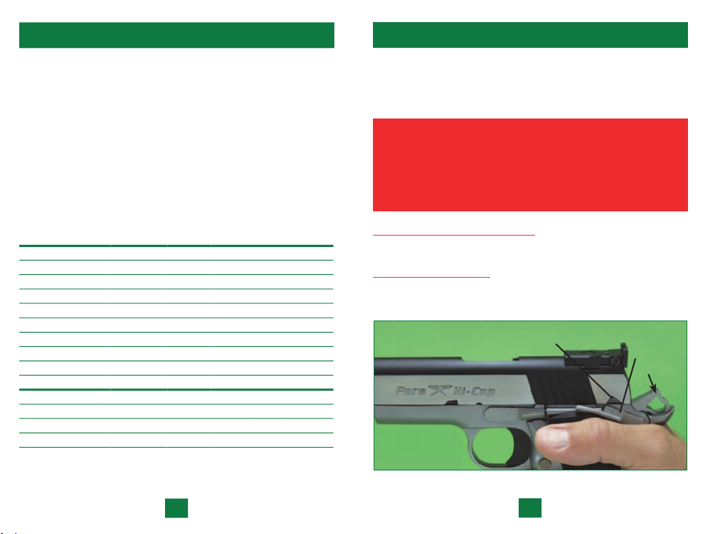
SLIDE LOCK SAFETY
This safety device can only be activated when the hammer is fully
cocked with slide fully forward
(Figure 1).
SLIDE LOCK
SAFETY NOTCH
Figure 1
SLIDE LOCK
SAFETY
HAMMER
8
9
Page 8
NEVER LEAVE YOUR PISTOL COCKED
AND READY TO FIRE.
THIS IS AN EXTREMELY DANGEROUS
CONDITION WHICH CAN LEAD TO AN
ACCIDENTAL DISCHARGE THAT MAY CAUSE
INJURY, DEATH, OR PROPERTY DAMAGE.
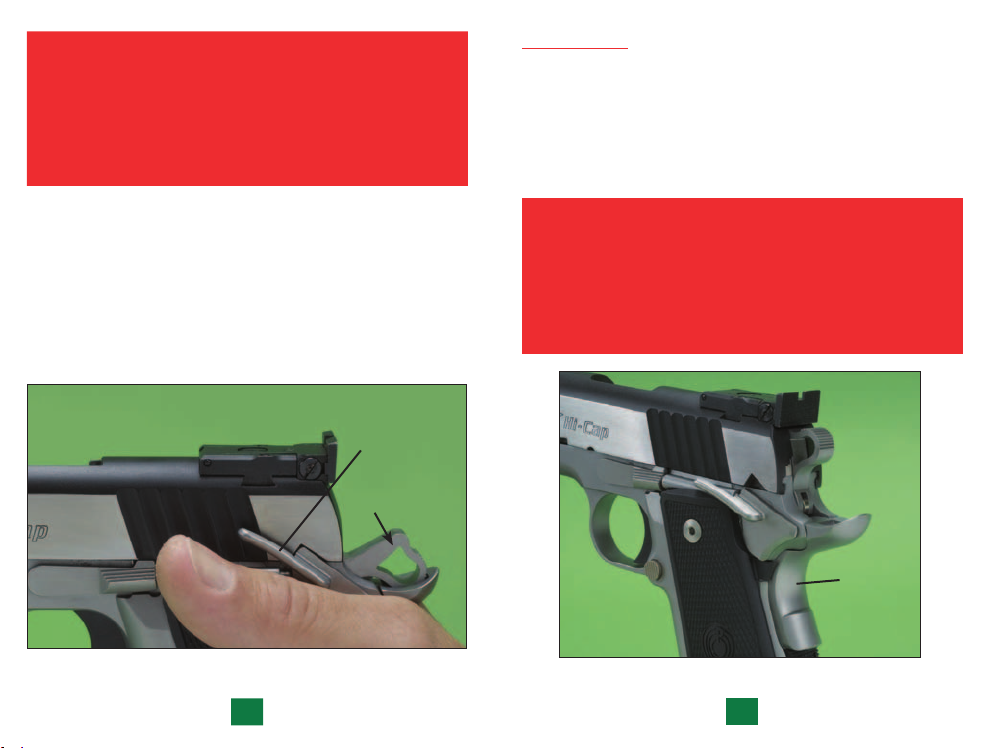
To engage the Slide Lock Safety you must, while pointing the
pistol in a safe direction with your finger away from the trigger,
pull the slide to its most rearward position and then let it return
all the way forward, freely and with all its force. This will leave
the hammer fully cocked. Then push the Slide Lock Safety up
until it fully engages the Slide Lock Notch
point, the slide is prevented from moving rearward and an
internal cam surface engages the sear to prevent the hammer
from moving forward if the trigger is pressed.
Figure 2
(Figure 2). At this
SLIDE LOCK
SAFETY
(ENGAGED)
HAMMER
(FULLY
COCKED)
GRIP SAFETY
The Grip Safety (Figure 3) prevents the rearward travel of the
trigger, which is necessary to fire the pistol, unless the pistol is
firmly in hand with a positive grasp of the Grip Safety. When
ready to fire the pistol with a firm hold on the receiver, the for
ward pressure that is applied to the Grip Safety disengages this
safety device and allows the trigger the necessary freedom for
rearward movement required to fire the pistol.
NEVER COMPROMISE SAFETY. NEVER ALTER
OR MODIFY THIS PISTOL IN ANY WAY.
THE MANUFACTURER WILL NOT
BE RESPONSIBLE FOR ANY
UNAUTHORIZED MODIFICATIONS
PERFORMED IN THIS GUN.
GRIP
SAFETY
(ACTIVE,
IN THE
OUT
POSITION)
Figure 3
10 11
Page 9

PASSIVE SAFETIES
THESE SAFETIES ARE ACTIVATED AUTOMATICALLY
WITHOUT MANUAL INTERVENTION. DO NOT BYPASS
THEM OR RENDER THEM INOPERATIVE.
These mechanisms form parts of a safety system incorporated
into your Para-Ordnance pistol and they are designed and installed
for the prevention of accidental discharges that could otherwise
follow as the result of some commonplace occurrences.
NEVER RELY ON A SAFETY MECHANISM TO
JUSTIFY CARELESS HANDLING OF YOUR PISTOL.
Your Para-Ordnance pistol is equipped with the following
passive safeties:
Disconnector: Protects against firing a round prior to its
being properly seated in the chamber of the barrel and
the slide and barrel not having locked together.
Inertia Firing Pin: Size and position of the firing pin, which
is held to the rear by a spring, keep the pin from striking
the cartridge primer unless the spring force and inertia of
the firing pin are overcome by the blow of the hammer.
Hammer Safety Stop: The hammer is designed with a flat, shelf-
like surface which is there to prevent the hammer from falling
forward and onto the firing pin unintentionally by engaging
the sear should there occur a primary sear notch failure.
Firing Pin Lock: To minimize the risk of accidental discharge
that may be the result of the pistol being dropped or
the muzzle receiving a blow, this safety device prevents
the movement of the firing pin until the trigger is
intentionally pressed.
ALWAYS EXPECT THE GUN TO FIRE
WHEN YOU PRESS THE TRIGGER.
FUNCTION
The action of the PXT Single-Action pistols is based on a
tilting barrel design that locks the barrel and slide together at
the moment of firing. After firing, the barrel and slide recoil to
the rear for a short distance still locked together. Following this
initial movement, the barrel tilts downward from its locked
position, permitting full recoil of the slide and the extraction
and ejection of the spent cartridge cases.
ALWAYS REMEMBER, THAT WHEN FIRED,
A SEMI-AUTOMATIC PISTOL RELOADS
AND RECOCKS ITSELF AUTOMATICALLY
AND IS READY TO FIRE AGAIN BY SIMPLY
PRESSING THE TRIGGER. ALWAYS KEEP THE
PISTOL POINTED IN A SAFE DIRECTION.
MALFUNCTIONS
1. In any semi-automatic pistol, an unfired cartridge or fired
cartridge case may become jammed between the slide
and barrel.
NEVER FORCE A JAMMED ACTION.
TO DO SO MAY CAUSE AN EXPLOSION THAT
CAN RESULT IN SERIOUS INJURY, DEATH
OR PROPERTY DAMAGE.
To clear a jammed cartridge, KEEP THE MUZZLE POINTED
IN A SAFE DIRECTION and remove the magazine. Pull the
slide back and lock it to the rear by engaging the Slide Stop.
Remove the cartridge.
12 13
Page 10
2. STOP SHOOTING IMMEDIATELY if you encounter any
other mechanical malfunction while firing your pistol, e.g.,
cartridge has failed to extract, report on firing does not sound
right, powder gas is being “spit out,” cartridge primer is punc
tured or cartridge case is bulged or punctured. HAVE THE
FIREARM AND AMMUNITION EXAMINED BY
A COMPETENT GUNSMITH.
3. FAILURE TO FIRE: KEEP THE MUZZLE POINTED
IN A SAFE DIRECTION and hold it there for 30 seconds
to determine if a HANGFIRE (slow ignition) has occurred.
If round has not fired within the 30 seconds, remove the
magazine, eject the round and examine the primer.
NOTE: Disposal of misfired or otherwise damaged, unfired
cartridges should be carried out according to instructions
provided by the manufacturer of the ammunition.
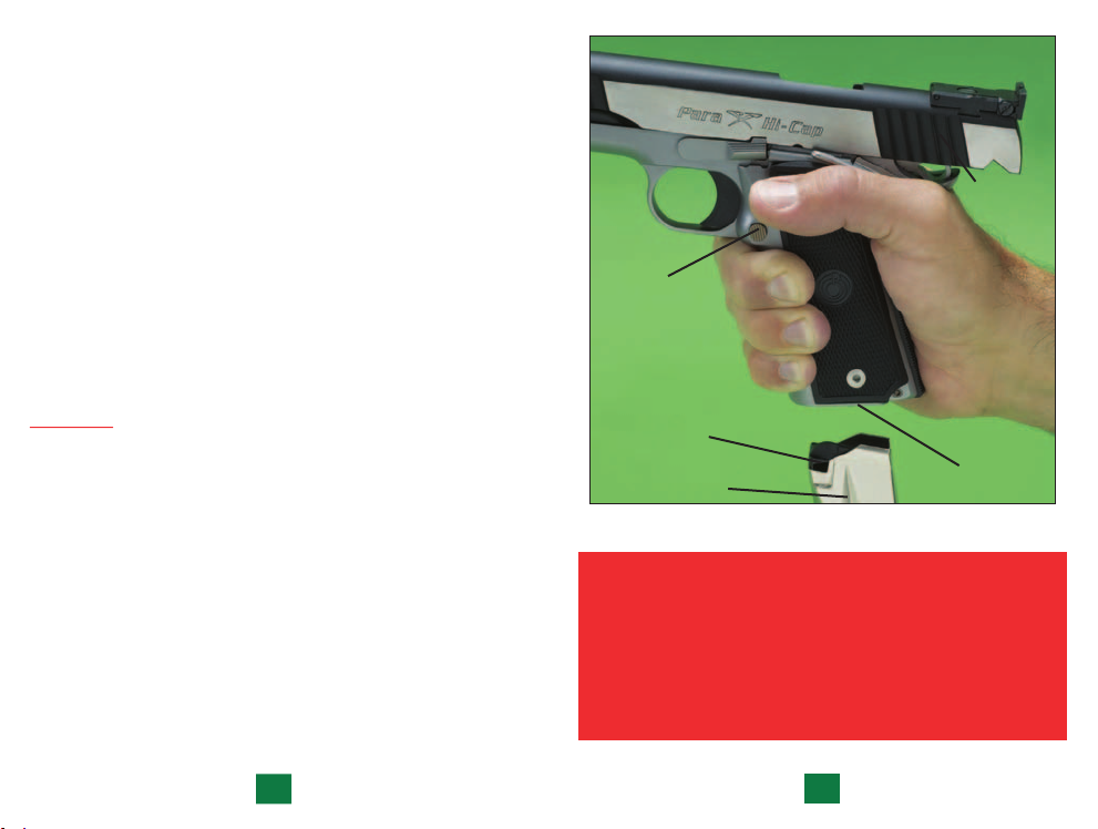
-
MAGAZINE
CATCH
BUTTON
SERRATED
FINGER
GROOVES
LOADING
PRACTICE THESE IMPORTANT ASPECTS OF SAFE GUN
HANDLING WITH AN UNLOADED PISTOL OR WITH DUMMY
ROUNDS UNTIL YOU ARE ABLE TO PERFORM EACH OF THE
FOLLOWING STEPS WITH SKILL AND CONFIDENCE. READ
THROUGH THIS MANUAL COMPLETELY BEFORE MAKING
ACTUAL USE OF THIS PISTOL.
1. Remove the empty magazine from your pistol by
pressing on the Magazine Catch button
(Figure 4).
NOTE: As the magazine will fall free from the receiver
of its own weight, place one hand under the magazine
to prevent it from dropping to the ground and having
it damaged.
14
MAGAZINE
FOLLOWER
MAGAZINE
MAGAZINE
WELL
Figure 4
DO NOT LOAD DAMAGED AMMUNITION. ALWAYS
LOAD YOUR MAGAZINE WITH CLEAN, DRY,
ORIGINAL HIGH QUALITY FACTORY MADE
AMMUNITION THAT IS IN GOOD
CONDITION AND THE PROPER CALIBER
FOR YOUR PISTOL (TABLE 1).
PRACTICE WITH DUMMY CARTRIDGES.
15
Page 11
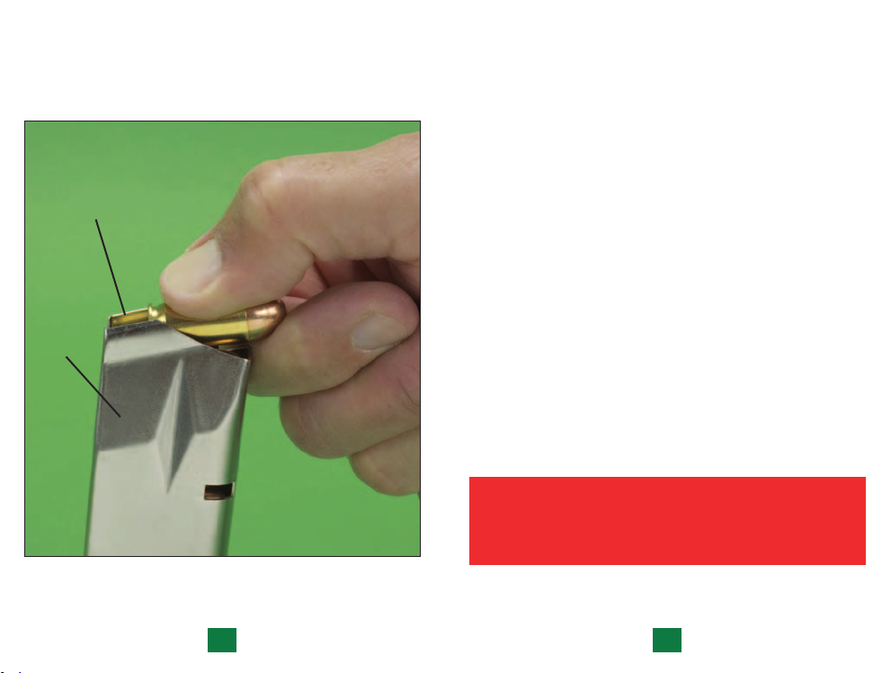
2. Load magazine from the top open end, the front of the
cartridge pointing away from you, with the type and
quantity of ammunition for your pistol
Press rounds down and back
RETAINING LIPS
MAGAZINE
(Figure 5).
Figure 5
(Table 1).
3. ENSURE THAT THE BARREL CHAMBER IS EMPTY
AND THAT THE BORE IS FREE OF OBSTRUCTIONS.
To do so, pull back on the slide, by grasping the serrated sides
of the slide from the rear, and take a look into the chamber and
bore. Having inspected the chamber and bore, and made sure
the chamber is empty, allow the slide to return to its forward
position. Where this step has caused the hammer to cock, press
the trigger causing the hammer to fall with an empty chamber.
4. Insert the magazine into the frame of the pistol with
cartridges pointing forward and make sure that the
magazine is pressed up far enough to lock into place.
NOTE: DO NOT SLAM THE MAGAZINE INTO PLACE.
5. WITH THE MUZZLE ALWAYS POINTED IN A SAFE
DIRECTION, hold the pistol firmly in the shooting
hand without touching the trigger. With the thumb and
forefinger of the other hand on the serrated finger grips
of the slide, pull the slide back, as far as it will go, to cock
the hammer. Release the slide and allow it to fly forward
with all its force and feed the top round from the magazine
into the chamber. THE PISTOL IS NOW READY FOR
INSTANT USE.
6. APPLY SLIDE LOCK SAFETY UNTIL YOU ARE READY
TO SHOOT.
NEVER LEAVE YOUR PISTOL IN THE COCKED
AND READY TO FIRE POSITION. THIS CONDITION
IS EXTREMELY DANGEROUS.
16
17
Page 12

LOADING - ALTERNATE SEQUENCE
PRACTICE THESE IMPORTANT ASPECTS OF SAFE GUN
HANDLING WITH AN UNLOADED PISTOL OR WITH DUMMY
ROUNDS UNTIL YOU ARE ABLE TO PERFORM EACH OF
THE FOLLOWING STEPS WITH SKILL AND CONFIDENCE.
READ THROUGH THIS MANUAL COMPLETELY BEFORE
MAKING ACTUAL USE OF THIS PISTOL.
1. Insert an EMPTY magazine (one with no cartridges in it) into
the frame of the pistol. Pull back on the slide, by grasping the
serrated sides of the slide from the rear, until the Magazine
Follower pushes the Slide Stop up into the Slide Stop Notch
on the slide
(Figure 4). The slide is now locked open in its
rearward position and the hammer is cocked.
2. Remove the empty magazine from your pistol by pressing
on the Magazine Catch button
(Figure 4). NOTE: As the
magazine will fall free from the receiver of its own weight,
place one hand under the magazine to prevent it from
dropping to the ground and having it damaged.
3. ENSURE THAT THE BARREL CHAMBER IS EMPTY
AND THAT THE BORE IS FREE OF OBSTRUCTIONS.
VISUALLY AND PHYSICALLY INSPECT THE BARREL
CHAMBER TO ENSURE THAT IT IS EMPTY. Insert a
loaded magazine into the frame of the pistol with cartridges
pointing forward and make sure that the magazine is pressed
up far enough to lock into place. NOTE: DO NOT SLAM
THE MAGAZINE INTO PLACE OR OVER INSERT IT.
4. WITH THE MUZZLE ALWAYS POINTED IN A SAFE
DIRECTION, hold the pistol firmly in the shooting hand
WITHOUT TOUCHING THE TRIGGER. Pull back on the
slide with the other hand, by grasping the serrated sides of the
slide from the rear, as far as it will go. Release the slide and
allow it to fly forward with all its force and feed the top round
from the magazine into the chamber. THE PISTOL IS NOW
READY FOR INSTANT USE.
5. APPLY SLIDE LOCK SAFETY UNTIL YOU ARE READY
TO SHOOT.
NEVER LEAVE YOUR PISTOL IN THE COCKED
AND READY TO FIRE POSITION. THIS CONDITION
IS EXTREMELY DANGEROUS.
UNLOADING
Always unload your pistol immediately after use and before
cleaning and storage.
YOU ARE WEARING SAFETY GLASSES AND KEEP THE
PISTOL POINTED AWAY FROM YOUR FACE.
FOLLOW THIS UNLOADING SEQUENCE EXACTLY IN ORDER
TO AVOID THE POSSIBILITY OF THE CHAMBER BEING
UNINTENTIONALLY LOADED WITH A LIVE CARTRIDGE.
1. WITH THE MUZZLE ALWAYS POINTED IN A SAFE
DIRECTION, hold the pistol firmly in the shooting hand
WITHOUT TOUCHING THE TRIGGER. Remove the
magazine by placing the other hand below it and pressing
the magazine catch button.
2. When unloading prior to the magazine having been totally
expended and the slide stop having latched the slide open,
keep your hands clear of the ejection port and pull the slide
back vigorously to extract and eject a round from the chamber.
NOTE: If the slide is locked open in its rearward position, this
step (Step #2) does not apply.
BEFORE PROCEEDING MAKE SURE
18 19
Page 13
3. CAUTION: INSPECT THE CHAMBER AND MAKE
SURE THAT IT IS EMPTY.
4. With pistol still pointing in a safe direction, release the
slide and allow it to snap forward on the empty chamber
and then press the trigger and let the hammer fall forward.
NOTE:
If the slide is locked open to its rearward position,
pull the slide back slightly and then release it.
5. If the magazine contains any cartridges, hold it with the
bullet end of the cartridges pointing away from you and
press each cartridge forward and out of the magazine.
6. SEGREGATE MISFIRED AND DAMAGED
AMMUNITION FOR DISPOSAL ACCORDING TO
AMMUNITION MANUFACTURER’S INSTRUCTIONS.
FIRING
ALWAYS WEAR AND ENCOURAGE OTHERS AROUND
YOU TO WEAR EAR PROTECTION AND SAFETY
GLASSES WHICH SHOULD PREVENT POSSIBLE
PERMANENT HEARING LOSS OR BLINDNESS.
1. WITH THE BARREL ALWAYS POINTING IN A SAFE
DIRECTION, load your pistol as previously described in
the section on “LOADING.”
2. With a firm hold on the pistol receiver, KEEPING YOUR
FINGER AWAY FROM THE TRIGGER, take aim and
press down on the Slide Lock Safety to disengage it from
the slide lock notch.
3. Take steady aim at your target and place your index finger
over the trigger. Press the trigger gently, pulling it to the back,
until the hammer falls on the firing pin.
THIS IS A SEMI-AUTOMATIC PISTOL THAT WHEN
FIRED, AUTOMATICALLY RELOADS AND RECOCKS
ITSELF AND IS READY TO FIRE AGAIN SIMPLY BY
PULLING THE TRIGGER.
4. Immediately following the firing of a shot, and if a
subsequent shot is not to be fired at once, apply the
Slide Lock Safety by pushing it into the slide lock notch.
However, if the last round has already been fired from
the magazine the slide will be locked to the rear with the
engagement of the Slide Stop and the Slide Lock Safety
cannot be applied.
5. WITH PISTOL POINTING IN A SAFE DIRECTION,
unload as previously described in section on “UNLOADING.”
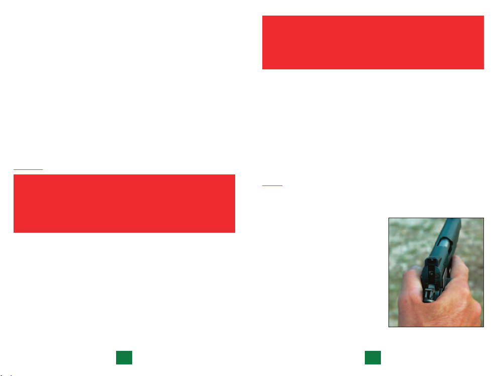
GRIP
For best performance, always be sure to grip the pistol firmly with
a locked wrist and insure that your hands don’t press upward on
the Slide Stop Lever or Slide Lock
Safety, as this can retard slide
movement and cause malfunctions.
Here are some tips on how to
properly hold your Para pistol from
champion shooter Todd Jarrett:
1. To reduce recoil, get as high as
possible to the center of the bore
with your holster-side hand yet
without touching the slide
(Figure 6). This is important for
high-speed shooting.
Figure 6
20
21
Page 14
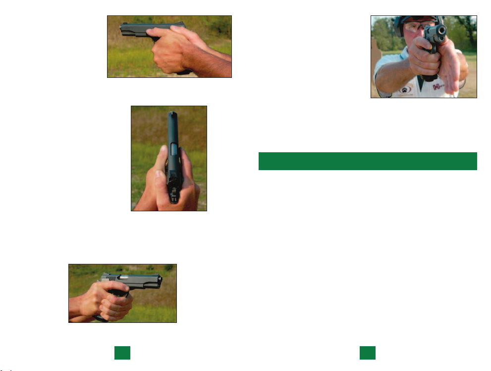
2. When holding a pistol,
your thumbs should be
pointing at the target
and sitting lightly on
the frame
Do not steer the pistol
with your thumb or
use it to add pressure.
3. When gripping a pistol, the
right hand thumb will always
be on top of the support
hand. You will see that
the weak hand thumb will
be parallel across from the
trigger finger
Remember, do not touch the
slide with any part of your
hand—it can disrupt the
cycle and cause the firearm
to malfunction.
4. When both hands are properly positioned on the pistol, there
should be an equal amount of pressure all around the frame
(Figure 9).
(Figure 7).
Figure 7
(Figure 8).
Figure 8
5. If you release the fingers
of your support hand while
still griping the pistol, your
fingers should be in a fortyfive degree downward angle
(Figure 10).
6. In an equal 50/50 grip, you
should apply about as much
pressure as if you were
swinging a bat or hammer.
7. Even the smallest difference in your hand position when
gripping a pistol will change the bullet impact on the target.
Figure 10
MAINTENANCE
Proper periodic maintenance is essential to the reliable
functioning of any firearm. The service life and performance
of the pistol depend upon correct handling and proper care.
All firearms require periodic maintenance and inspection
which may reveal a need for adjustment or repair.
You should clean your pistol as soon after firing as possible
and where your pistol has not been fired it should still be
cleaned periodically. Have your firearm checked by a
competent gunsmith annually, even if no functioning
problem exists, since some potential problems may not
be apparent from external examination of the pistol.
If the pistol gets wet, or is exposed to sand or other foreign
matter, have it cleaned as soon as possible.
Figure 9
22
23
Page 15
DISASSEMBLY
ALWAYS WEAR SAFETY GLASSES AND KEEP
PISTOL POINTED AWAY FROM YOUR FACE, WHEN
PREPARING TO STRIP AND CLEAN YOUR PISTOL
TO AVOID INJURY TO THE EYES IN THE EVENT
THAT SOME COMPONENT MAY COME FLYING
LOOSE FROM YOUR GUN.
STEP 3.
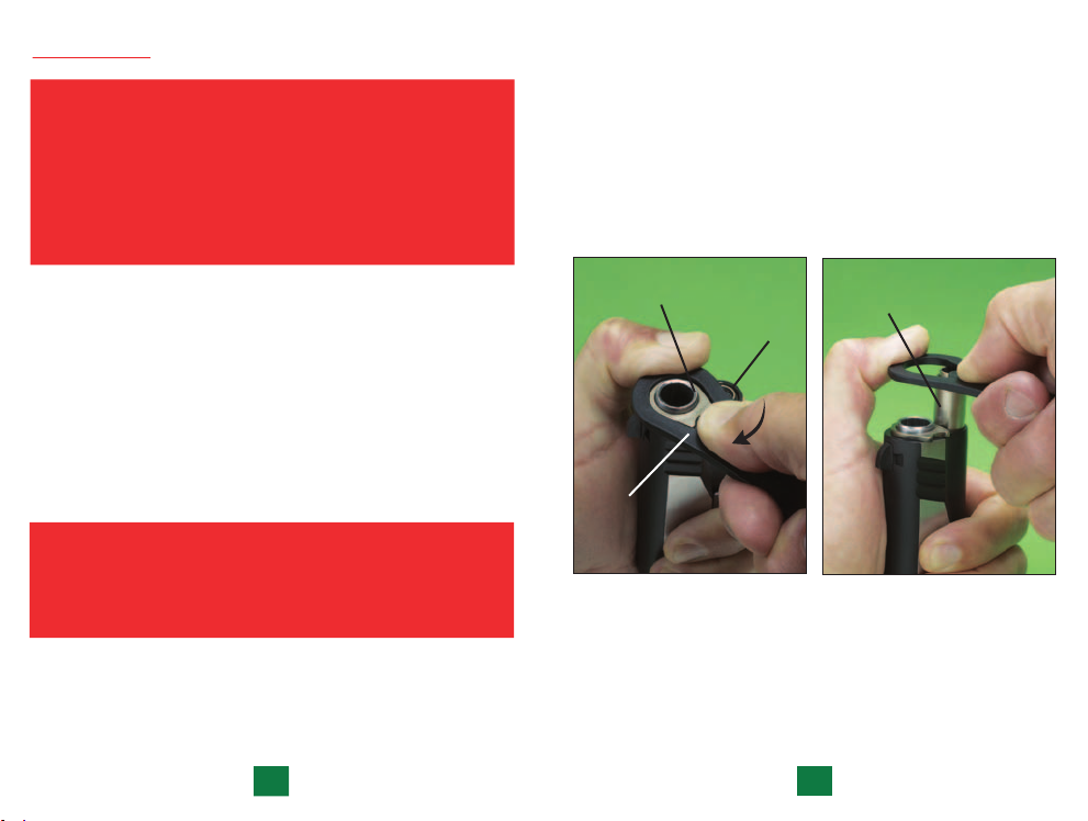
Using the barrel bushing wrench provided press down the
recoil spring plug (located below the muzzle) while at the
same time, rotating the barrel bushing clockwise for about
a quarter (1/4) turn so as to free the plug and recoil spring
(Figure 11).
Continue to apply pressure on the recoil spring plug to
prevent ejection of it and the spring. Then gently and
gradually allow the spring and the recoil spring plug to
extend out of the slide
(Figure 12).
Follow the steps for disassembly that apply to your pistol,
carefully.
STEP 1. Always make certain that the MAGAZINE HAS
BEEN REMOVED and your PISTOL IS NOT LOADED.
STEP 2. With barrel pointing upward and away from your face,
place the pistol with the back (heel) of the receiver and the
grip safety resting on a table or bench.
BEFORE PROCEEDING, MAKE SURE YOU ARE
WEARING SAFETY GLASSES AND KEEP THE
MUZZLE OF THE PISTOL POINTED
AWAY FROM YOUR FACE.
24
BARREL
BUSHING
BARREL
BUSHING
WRENCH
RECOIL
SPRING
PLUG
RECOIL
SPRING
PLUG
Figure 12 Figure 11
STEP 4. Pull back on hammer spur to cock the hammer.
25
Page 16
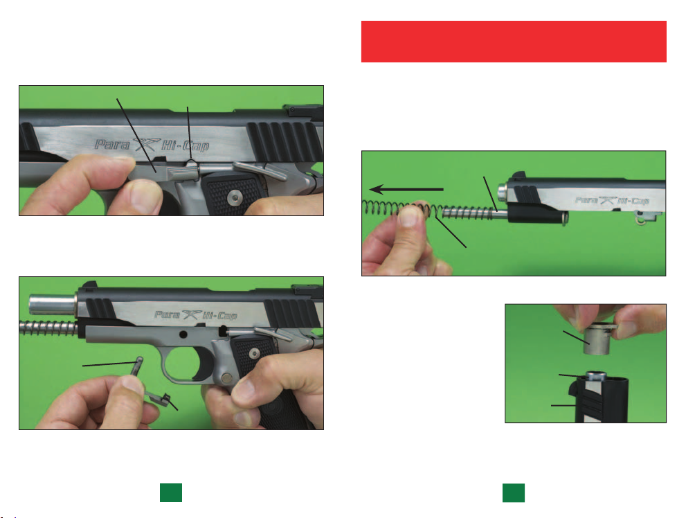
STEP 5. Push the slide back to the point that the slide stop lug is
directly opposite the disassembly notch
(Figure 13). Then push
the rounded end of the slide stop pin, on the right side of the
receiver, inward and through the receiver and out the left side.
SLIDE
STOP
DISASSEMBLY
NOTCH
Figure 13
Disengage slide stop from the slide by removing slide stop
completely from the receiver
SLIDE STOP
(Figure 14).
SLIDE
STOP LUG
Figure 14
STEP 6. Push slide forward and remove the slide from the
receiver.
NEVER DRY FIRE YOUR PISTOL WITH THE SLIDE
REMOVED FROM THE RECEIVER.
STEP 7. Pull recoil spring straight forward and remove it from
the recoil spring guide
reassemble the spring back on the guide, that the open end
of the spring should point forward). Lift the rear of the
recoil spring guide toward the rear and out of the slide.
STEP 8. To remove the
barrel bushing from the
barrel, turn the bushing
counter-clockwise and
then push the barrel and
bushing forward to the
point that the bushing is
clear of the slide and
can be removed from
the barrel
(Figure 16).
STEP 9. With barrel
bushing already removed, push barrel link forward and remove
the barrel through the front of the slide.
(Figure 15) (remember, when you
RECOIL
SPRING
GUIDE
RECOIL SPRING
Figure 15
BARREL
BUSHING
BARREL
SLIDE
Figure 16
26
27
Page 17
DO NOT DISASSEMBLE YOUR PISTOL
ANY FURTHER. DO NOT REMOVE OR ALTER ANY
PARTS, ESPECIALLY SAFETY PARTS.
If your pistol requires further work it should be done at an
Authorized Service Center or at the factory.
REASSEMBLY
BEFORE PROCEEDING, MAKE SURE YOU ARE
WEARING SAFETY GLASSES AND KEEP THE
MUZZLE OF THE PISTOL POINTED
AWAY FROM YOUR FACE.
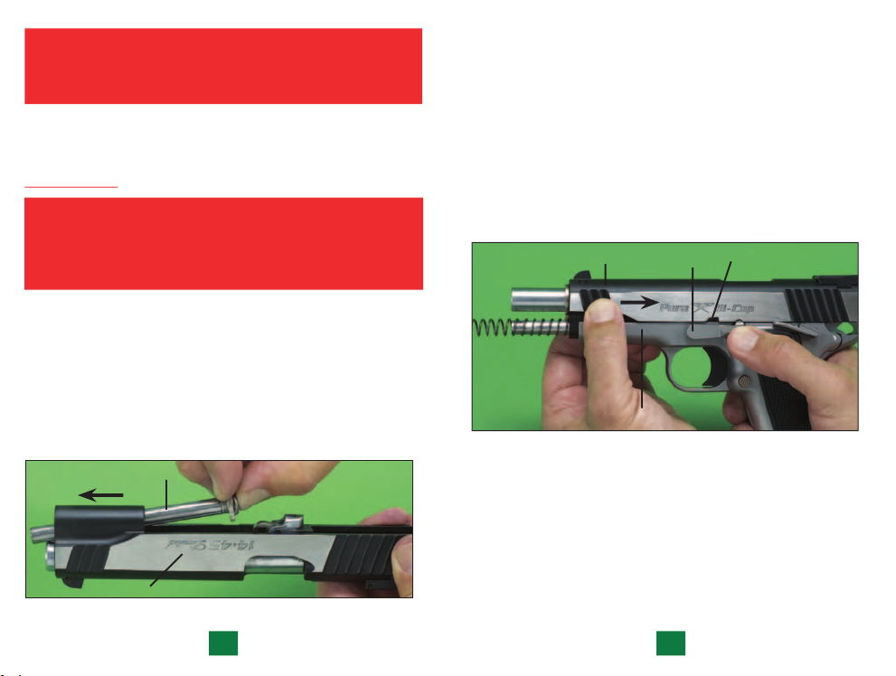
STEP 1. Rotate barrel link forward and install the barrel
through the front of the slide.
STEP 2. To install the barrel bushing on the barrel, push
the barrel forward enough to allow you to slide the barrel
bushing onto it. Then push the bushing rearward until it
contacts the slide. Turn it clockwise to engage it in the slide.
STEP 3. Insert recoil guide by pushing it toward the front of
the slide
(Figure 17).
RECOIL
GUIDE
STEP 4. Slip recoil spring, closed end first, over the front of
the recoil spring guide, until the spring end makes contact
with the base of the guide.
STEP 5.
Make sure the plunger lever is down (forward) at
the top of the receiver, and keep it down by tipping the
receiver forward. Wrap your fingers around the front of the
slide to hold the recoil spring assembly in position. Now
you can run the slide onto the receiver to the point where
you can see the barrel link through the slide stop hole in the
receiver. Insert the slide stop pin in and through the receiver
and barrel link.
SLIDE
SLIDE STOP
FRAME
Figure 18
STEP 6. Grip the frame with one hand and the slide with the
other (Figure 18). Now push the slide rearward to properly
align the disassembly notch. Snap the slide stop pin into place
by pressing up and against the slide stop detent.
DISASSEMBLY
NOTCH
SLIDE
Figure 17
28
29
Page 18
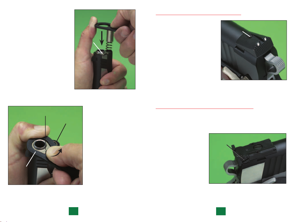
STEP 7. Push the slide
fully forward. Slip the
recoil plug over the end of
the recoil spring. Using the
barrel bushing wrench
apply and maintain
pressure on the plug,
gently and gradually push
the spring and plug into
the slide far enough so
that you can rotate the
barrel bushing with the
wrench counter-clockwise
slightly and hold the plug
(Figure 19).
in place
SIGHT ADJUSTMENT - Fixed Sights
The rear sight is adjustable
BARREL
BUSHING
Figure 19
for windage only. Using a
5/64" hex wrench which
has been provided, loosen
the hex set screw located
directly in front of the
rear sight notch. You may
now change windage by
moving the rear sight either
left or right in its dovetail.
Remember, always move
your rear sight in the
direction you want your
bullet’s impact to go.
SET SCREW
Figure 21
BARREL BUSHING
BARREL
BUSHING
WRENCH
Figure 20
RECOIL
SPRING
PLUG
Now, place your
30
bushing wrench
over the bushing
and, while pressing
the wrench down
firmly to hold the
plug down, rotate
the bushing
counter-clockwise
until the plug can
snap into place
(Figure 20).
SIGHT ADJUSTMENT - Adjustable Sights
To adjust your rear sight for elevation, use the largest blade of
the screwdriver which has been provided. To raise the sight
and thus raise the impact point of the bullet, turn the screw
counter-clockwise.
To adjust for windage
(Figure 22), turn the
WINDAGE
ADJUSTMENT
SCREW
screw on the right
side of the rear sight
clockwise to move the
bullet’s impact to the
right; counterclockwise to move
impact to the left.
Figure 22
31
Page 19
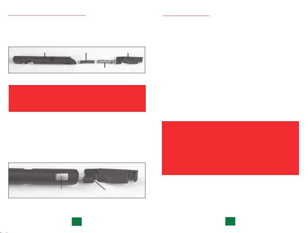
POWER EXTRACTOR ASSEMBLY
The Power Extractor Assembly Consists of four parts: body,
coil spring, plunger and claw. The body (Figure 23) contains
the coil spring and plunger and the key at the rear of the claw
hooks into the window at the front of the body.
BODY COIL SPRING
PLUNGER
Figure 23
CLAW
ALWAYS WEAR SAFETY GLASSES
BEFORE DISASSEMBLING ANY PART
THAT CONTAINS A SPRING.
Being careful not to launch the plunger, swing the key
(Figure 24) at the rear of the claw out of the window in the
body and away from the plunger. The plunger and the coil
spring can now be removed from the body. To reassemble,
insert the coil spring into the body followed by the plunger.
Push the rear of the claw against the plunger and insert the
key at the rear of the claw into the body window.
CLEANING PISTOL
1. Disassemble (field-strip) the pistol to the extent described
on pages 22 through 30.
2. Clean your pistol by brushing the barrel bore and chamber
with a good powder-removing solvent and bore brush. Wipe
the areas clean with patches or a swab.
3. Using a small brush dipped in solvent, remove all deposits
from around the breech of the barrel, chamber, extractor
and adjacent areas which have been subjected to powder
residue. Wipe all surfaces clean with patch or swab.
4. After cleaning the entire pistol, use a cloth to apply a light
coating of high quality gun oil by passing it once through
the barrel and all other surfaces.
NOTE: Excess accumulations of oil can interfere with the
safe and reliable function of the pistol.
ALWAYS PASS A DRY PATCH THROUGH THE
BARREL TO REMOVE AS MUCH OIL AS POSSIBLE
PRIOR TO USING PISTOL. FIRING THE PISTOL
WITH OIL, GREASE OR ANY OTHER MATERIAL EVEN
PARTIALLY OBSTRUCTING THE BORE MAY RESULT IN
DAMAGE TO THE PISTOL WHICH CAN CAUSE INJURY,
DEATH, OR PROPERTY DAMAGE.
WINDOW
Figure 24
32
KEY
33
Page 20
BEFORE PROCEEDING MAKE SURE YOU ARE
WEARING SAFETY GLASSES AND KEEP THE
MAGAZINE POINTED AWAY FROM YOUR FACE.
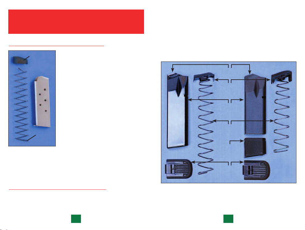
CLEANING SINGLE-STACK MAGAZINES
FOLLOWER
MAGAZINE
BODY
SPRING
Figure 25
uppermost and pointed forward, back into magazine, compress
spring and insert thin rod as previously directed. Place follower
in magazine and remove the thin rod to allow the spring to press
follower into its correct position.
This should be done whenever cleaning
the pistol. Remove the magazine
follower and spring by depressing them
with a pencil or wooden dowel about
2” into the magazine and inserting
a thin rod through the lower of the
front two holes in the magazine body.
Turn the magazine upside down and
tap it, so the follower falls away from
the spring. Remove the follower from
the magazine body. Now, push down
on the spring to take up the tension,
and remove the thin rod. You can now
remove the spring from the magazine
(Figure 25).
Clean the follower, spring and
magazine body. Lubricate lightly.
To reassemble, insert spring, with loop
floor plate out of the way, remove the spring and follower. Clean
all components, taking care to remove any powder deposits on
the magazine retaining lips and follower (Figure 26).
NOTE: Place spring correctly oriented with closed loop
uppermost pointing forward.
High-Capacity
Magazine Assembly
MAGAZINE
RETAINING LIPS
MAGAZINE
FOLLOWER
MAGAZINE
BODY
MAGAZINE
SPRING
MAGAZINE
EXTENSION
MAGAZINE
FLOOR
PLATE
10-Round
Magazine Assembly
CLEANING HIGH-CAPACITY MAGAZINE
This should be done whenever cleaning the pistol. Slide magazine
floor plate toward the front of the magazine, taking care to avoid
forcible ejection of the magazine spring from the body. With the
34
Figure 26
H
IGH-CAPACITY MAGAZINE (LEFT) IS FOR LAW ENFORCEMENT
ONLY. FOR RECREATIONAL USE, MAGAZINE CAPACITY IS
RESTRICTED TO 10 ROUNDS IN THE U.S.A. AND CANADA.
35
Page 21
DISASSEMBLY, CLEANING & REASSEMBLY OF
10-ROUND PARA-ORDNANCE MAGAZINE
BEFORE PROCEEDING MAKE SURE
YOU ARE WEARING SAFETY GLASSES
AND KEEP THE MAGAZINE
POINTED AWAY FROM YOUR FACE.
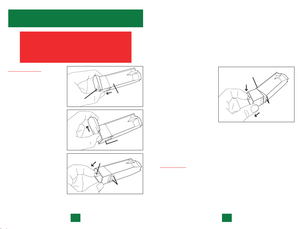
DISASSEMBLY
STEP 1: Remove all
ammunition from
magazine. Firmly grasp
the metal magazine
body in one hand and
with the other hand
grip the magazine’s base
plate. Use your thumb
to slightly raise the
slotted tab at the rear
of the base plate.
CAUTION:
slotted tab only enough
to clear the rear of the
magazine extension.
S
TEP 2: Slide the base plate
towards the front of the
magazine to remove it.
TEP 3: While holding the
S
magazine in one hand,
use the index finger of
the other hand to gently apply a small amount of pressure to
the release lever at the bottom of the magazine extension.
Lift the
the
SLOTTED
TAB ON
BASE PLATE
RELEASE
LEVER
METAL
MAGAZINE
BODY
MAGAZINE
EXTENSION
(REAR)
TWO SMALL
TABS (REAR)
This will retract the two small tabs at the rear of the extension
which keep it in place. Gently increase the pressure on the
release lever until some resistance is felt.
CAUTION:
Do not apply excessive pressure to the release lever
or it may break off.
CAUTION: The spring and follower are compressed in the
magazine. Care should be taken during this step to prevent
them from flying out.
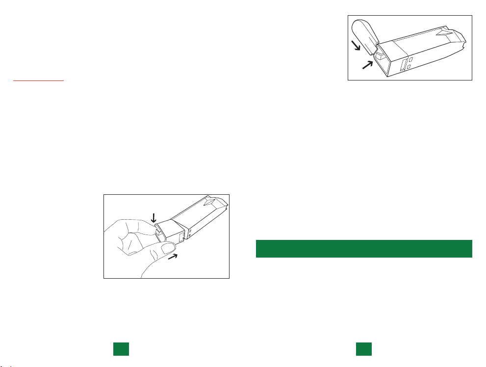
STEP 4: While maintaining
the gentle pressure on
the release lever, begin
ROUND TAB
(FRONT)
to rotate the magazine
extension downward to
release it from the metal
magazine body. Release
pressure from the lever
as soon as the two small
tabs at the top rear of
TWO
SMALL
TABS
(REAR)
the extension clear the
magazine body. The extension can now be removed by easing
it slightly rearward to release the round tab at the front. The
spring and magazine follower can now be removed through
the opening at the bottom of the metal magazine body. As you
remove it, note which end faces the front.
CLEANING
CAUTION: Do not attempt to remove the follower from the
spring.
Wipe the outside of the magazine with a rag. Insert a dry rag
through the opening at the bottom of the metal magazine
body and remove all residue from the inside. Do the same
from the smaller opening at the top.
36
37
Page 22
Clean all residue from the spring and from the magazine
follower.
CAUTION:
of the magazine.
Do not apply oil to any part or lubricate any part
REASSEMBLY
STEP 1: Insert the spring and follower into the opening at the
bottom of the metal magazine body
CAUTION:
follower is at the front of the magazine.
Position the bottom of the spring around the four posts on
the magazine extension. Then, gently compress the spring with
the magazine extension so that it is fully contained inside the
magazine body. Engage the round tab at the top front of the
magazine extension in the small hole at the front of the
magazine body.
While still holding the
spring compressed,
gently apply a
amount of rearward
pressure to the lever
at the bottom of the
extension until some
resistance is felt.
Then, rotate the rear
of the extension
upwards so it engages the magazine body. Continue
until the two small tabs are fully engaged.
Release the pressure from the lever at the bottom of
extension. The magazine extension is now locked in place.
Make sure that the rounded top edge of the
tiny
rotating
the
STEP 2: With your index
finger, gently depress
the lever at
bottom of the
extension. This will
allow you to replace
the base plate without
breaking the tab.
While holding the lever in a depressed position, begin to
replace the base plate by sliding it rearward from the front of
the extension. Be sure that the base plate engages the two rails
on the sides of the extension.
Continue to slide the base plate towards the rear until a click
is heard, indicating that the slotted tab at the rear of the base
plate has passed over the rear edge of the extension, locking it
in place.
Reassembly is now complete.
These instructions apply to all 10-round magazines for
Para-Ordnance P-Series and S-Series handguns except the
Warthog. In order to clean and disassemble the Warthog,
follow the instructions on page 34 for the hi-cap magazine.
the
TRANSPORTATION AND STORAGE
When transporting your firearm to and from shooting activities,
keep it unloaded and obey all laws relating to the transportation
of firearms in your area.
When storing your firearm, store it securely and keep it separated
from ammunition, under lock and key, and out of the sight and
reach of children and other inexperienced persons.
N
OTE: Protect your firearms from theft.
38
39
Page 23

DO NOT STORE your pistol in anything which will attract
moisture, e.g., leather or heavy cloth, and do not store it in an
air-tight container or with a plug inserted in the barrel for these
are factors that can contribute to corrosion.
EXTENDED STORAGE requires that the internal mechanisms
are well oiled with an acid-free lubricating oil or preservative
while external mechanisms (receiver, barrel, etc.) should be
coated with an anti-rust oil.
COLD CLIMATE STORAGE requires that you make use of an
oil which will not congeal at low temperatures. USE SPARINGLY.
BEFORE USING YOUR FIREARM AGAIN, BE SURE TO
CLEAN IT.
SERVICE AND REPAIR
If any problem or question should arise with regard to the
performance of your firearm, please contact us, by mail or
telephone, and fully describe all circumstances involved. This will
allow us to determine the best way to handle your problem. If
authorized factory service is deemed necessary, you will be given a
return authorization number and shipping instructions.
MAKE SURE THAT THE MAGAZINE AND
PISTOL ARE UNLOADED. DO NOT SHIP ANY
CARTRIDGES WITH A FIREARM.
WARRANTY INFORMATION
Para-Ordnance acknowledges its obligations under implied
warranty legislation, with respect to the sale of consumer goods,
that may be in force in jurisdictions where its products are sold.
Due to differences in the extent and interpretation of such stat
utes, and also on the basis of the Magnusson-Moss Warranty Act
of the United States of America, Para-Ordnance has elected not
to offer any written or express warranty on its product line and
you are advised to consult existing legislation in your country,
state or province with regard to any implied warranty rights you
may have under such laws. However, Para-Ordnance is strongly
committed to properly servicing its products, as it has over the
years, and in place of an express or written warranty it will pro
vide all necessary service for its pistols purchased after January 1,
2001 free of charge to the original purchaser only, where adjustment or repair is required due to some defect in materials or
workmanship.
N
OTE: Different remedies may be available to you in different
jurisdictions.
-
-
40
WHEN AUTHORIZED TO SHIP YOUR FIREARM FOR ADJUSTMENT
OR REPAIR, PLEASE CAREFULLY NOTE THE FOLLOWING:
1. A detailed, written explanation of your problem should
accompany the firearm being shipped for service or repair.
Include model name, serial number and your return address
(day telephone number optional). Also include a copy of your
original proof of purchase.
2. All firearms should be shipped by common carrier (e.g., UPS),
prepaid (we will not accept collect shipments) and insured for
their full value. It is illegal for unlicensed individuals to ship
handguns through the mail.
3. Due to the vast number of laws governing the transfer and
transportation of firearms, it is strongly recommended that
your firearm be shipped through a licensed dealer who will
also accept delivery on your behalf when the pistol is returned.
The shipment should be accompanied by a signed copy of the
dealer’s license.
4. DO NOT include holsters, custom grips or other accessories
when shipping your firearm for service.
41
Page 24

5. DO NOT indicate the nature of the contents on the package
or use the “Para-Ordnance” name to address the shipment.
6. DO include the return authorization number on the outside of
the package.
LIMITS OF LIABILITY
NOTE: PARA-ORDNANCE HAS CAREFULLY PACKAGED THIS
PRODUCT PRIOR TO SHIPMENT FROM THE FACTORY.
PLEASE EXAMINE IT CAREFULLY AT TIME OF PURCHASE
TO ENSURE IT IS UNDAMAGED.
PARA-ORDNANCE SHALL NOT BE RESPONSIBLE IN ANY
MANNER WHATSOEVER FOR INJURY, DEATH, OR DAMAGE
TO PROPERTY AS A RESULT OF THE INTENTIONAL OR
ACCIDENTAL DISCHARGE OF THIS FIREARM, OR FROM
ITS PROPER FUNCTION WHEN THE PISTOL IS USED
FOR PURPOSES FOR WHICH IT WAS NOT DESIGNED.
FURTHERMORE, PARA-ORDNANCE SHALL NOT BE
RESPONSIBLE FOR ANY CLAIMS THAT MAY ARISE
AS A RESULT OF, WHETHER IN WHOLE OR IN PART,
IMPROPER OR CARELESS HANDLING, UNAUTHORIZED
MODIFICATIONS, USE OF IMPROPER AMMUNITION
(WRONG CALIBER, DEFECTIVE, HAND LOADED, OR
RELOADED CARTRIDGES) THAT IS NOT ORIGINAL HIGH
QUALITY COMMERCIALLY MANUFACTURED AND IN
GOOD CONDITION, ABUSE, NEGLECT, CORROSION, OR
OTHER INFLUENCES BEYOND OUR IMMEDIATE AND
DIRECT CONTROL. UNDER NO CIRCUMSTANCES SHALL
PARA-ORDNANCE BE RESPONSIBLE FOR INCIDENTAL
OR CONSEQUENTIAL DAMAGES, SUCH AS LOSS OF USE
OF PROPERTY, LOSS OF EARNINGS OR PROFITS, OR ANY
OTHER COMMERCIAL LOSS.
NOTE: DIFFERENT REMEDIES MAY BE AVAILABLE TO YOU
IN DIFFERENT JURISDICTIONS.
SPARE PARTS
For Para-Ordnance replacement parts please contact your local
dealer who should be able to assist you. Alternatively, you can also
contact the Para-Ordnance Parts Department by mail or phone,
for up-to-date information on the names and locations of our
Authorized Service Centers as well as current parts prices.
PARTS AVAILABLE FOR SALE SHOULD BE INSTALLED
AT A PARA-ORDNANCE AUTHORIZED SERVICE
CENTER. OTHERWISE, IT IS THE PURCHASER’S TOTAL
RESPONSIBILITY TO MAKE ABSOLUTELY CERTAIN
THAT ANY PARTS FITTED AND INSTALLED ARE OF THE
CORRECT TYPE AND THE WORK IS PERFORMED BY A
COMPETENT PERSON.
PARA-ORDNANCE WILL NOT BE RESPONSIBLE
FOR ANY UNAUTHORIZED ALTERATIONS
PERFORMED, UNAUTHORIZED ATTACHMENTS
FITTED OR UNAUTHORIZED PARTS
USED 0N THIS PRODUCT.
NOTES:
42
43
Page 25
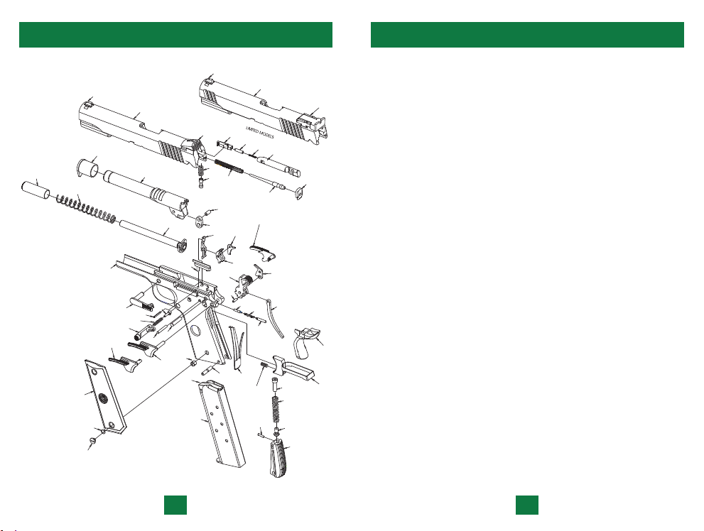
SINGLE STACK PARTS ILLUSTRATION
SINGLE STACK
MAGAZINE
1
2
3
4
5
6
7
8A
8B
8C
8D
9
10
11
12
13
14
15
16
17
18
19
19A
19B
21
25
23
24
20
22
26
27
28
30
31
32
33
35
36
37
38
39
40
41
42
43
44
45
46
47
48
49
50
51
52
53
54L
54R
55
34
SINGLE STACK PARTS LIST
1. BARREL
2. BARREL BUSHING
3. BARREL LINK
4. BARREL LINK PIN
44
5. DISCONNECTOR
6. EJECTOR
7. EJECTOR PIN
8A. EXTRACTOR CLAW
8B. EXTRACTOR BODY
8C. EXTRACTOR
8D. EXTRACTOR
9. FIRING PIN
10. FIRING PIN PLUNGER
11. FIRING PIN SPRING
12. FIRING PIN STOP
13. FRONT SIGHT
14. FRONT SIGHT (LIMITED)
15. FIXED REAR SIGHT
PLUNGER
SPRING
16. ADJUSTABLE REAR SIGHT
(LIMITED)
17. GRIP SAFETY
18. GRIP (SET)
19. GRIP SCREW (4)
19A. GRIP SCREW LOCKING
RINGS
19B. GRIP SCREW BUSHING
20. HAMMER
21. HAMMER PIN
22. HAMMER STRUT
23. HAMMER STRUT PIN
24. MAGAZINE ASSEMBLY
25. MAGAZINE CATCH
26. MAGAZINE CATCH LOCK
27. MAGAZINE CATCH
SPRING
28. MAGAZINE FOLLOWER
29. MAGAZINE SPRING
(NOT SHOWN)
30. MAIN SPRING
31. MAIN SPRING CAP
32. MAIN SPRING CAP PIN
33. MAIN SPRING HOUSING
(FLAT)
34. MAIN SPRING HOUSING
PIN
35. MAIN SPRING HOUSING
PIN RETAINER
36. PLUNGER LEVER
37. PLUNGER SPRING
38. PLUNGER SPRING F/P
39. RECEIVER
40. RECOIL SPRING
41. RECOIL SPRING GUIDE
42. RECOIL SPRING PLUG
43. SLIDE LOCK SAFETY
44. SAFETY LOCK PLUNGER
45. SEAR
46. SEAR PIN
47. SEAR SPRING
48. SLIDE
49. SLIDE (LIMITED)
50. SLIDE STOP
51. SLIDE STOP PLUNGER
52. TRIGGER ASSEMBLY
53. TRIGGER BAR LEVER
54L. AMBIDEXTROUS SLIDE
LOCK SAFETY LEFT
(LIMITED ONLY)
54R. AMBIDEXTROUS SLIDE
LOCK SAFETY RIGHT
(LIMITED ONLY)
55. OVER TRAVEL SCREW
(LIMITED ONLY)
45
Page 26
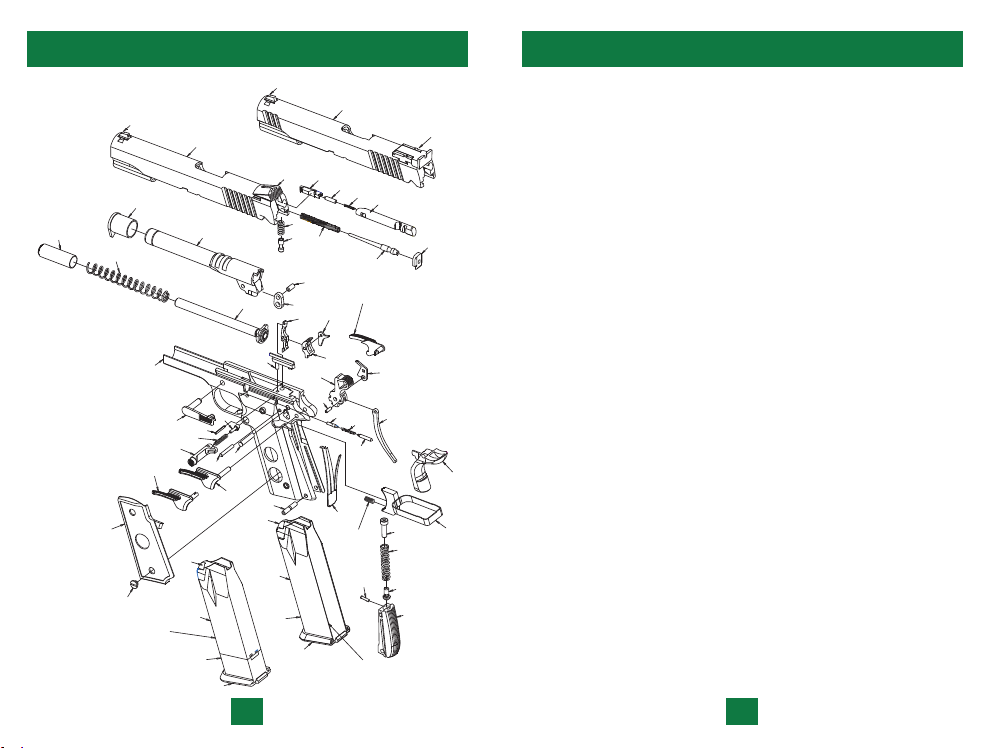
HIGH-CAPACITY PARTS ILLUSTRATION
1
2
3
4
5
6
7
8A
8B
8C
8D
9
10
11
12
13
14
15
16
18
17
19
20
21
24
24
25
23
27
28
28
29
29
30
30
32
33
34
35
36
37
38
39
40
41
42
43
44
45
46
47
48
49
50
51
52
53
54
55
56L
56R
57
26
22
HIGH-CAPACITY PARTS ILLUSTRATION
1. BARREL
2. BARREL BUSHING
46
3. BARREL LINK
4. BARREL LINK PIN
5. DISCONNECTOR
6. EJECTOR
7. EJECTOR PIN
8A. EXTRACTOR CLAW
8B. EXTRACTOR BODY
8C. EXTRACTOR
8D. EXTRACTOR
9. FIRING PIN
10. FIRING PIN PLUNGER
11. FIRING PIN SPRING
12. FIRING PIN STOP
13. FRONT SIGHT
14. FRONT SIGHT (LIMITED)
15. FIXED REAR SIGHT
PLUNGER
SPRING
16. ADJUSTABLE REAR SIGHT
(LIMITED)
17. GRIP SAFETY
18. GRIP (SET)
19. GRIP SCREW (4)
20. HAMMER
21. HAMMER PIN
22. HAMMER STRUT
23. HAMMER STRUT PIN
24. MAGAZINE ASSEMBLY
25. MAGAZINE CATCH
26. MAGAZINE CATCH LOCK
27. MAGAZINE CATCH
SPRING
28. MAGAZINE FLOOR PLATE
29. MAGAZINE EXTENSION
(10-ROUND ONLY)
30. MAGAZINE FOLLOWER
31. MAGAZINE SPRING
(NOT SHOWN)
32. MAIN SPRING
33. MAIN SPRING CAP
34. MAIN SPRING CAP PIN
35. MAIN SPRING HOUSING
(FLAT)
36. MAIN SPRING HOUSING
PIN
37. MAIN SPRING HOUSING
PIN RETAINER
38. PLUNGER LEVER
39. PLUNGER SPRING
40. PLUNGER SPRING F/P
41. RECEIVER
42. RECOIL SPRING
43. RECOIL SPRING GUIDE
44. RECOIL SPRING PLUG
45. SLIDE LOCK SAFETY
46. SAFETY LOCK PLUNGER
47. SEAR
48. SEAR PIN
49. SEAR SPRING
50. SLIDE
51. SLIDE (LIMITED)
52. SLIDE STOP
53. SLIDE STOP PLUNGER
54. TRIGGER ASSEMBLY
55. TRIGGER BAR LEVER
56L. AMBIDEXTROUS SLIDE
LOCK SAFETY LEFT
(LIMITED ONLY)
56R. AMBIDEXTROUS SLIDE
LOCK SAFETY RIGHT
(LIMITED ONLY)
57. OVER TRAVEL SCREW
(LIMITED ONLY)
47
Page 27

FIREARM RECORD
MODEL
SERIAL NO.
PURCHASED FROM
DATE PURCHASED
This instruction manual should always accompany this firearm
and be transferred with it upon change of ownership.
Para
980 TAPSCOTT ROAD
SCARBOROUGH, ONTARIO M1X 1C3
(416) 297-7855 • FAX: (416) 297-1289
www.paraord.com
MANUAL #P
O0704S
 Loading...