

Page 1

Page 2

You're Part of the Tradition'
In a sport
names in hunting and shooting. To be sure, the Golden Ring" scope you now
own is the finest example of Leupold heritage. -
Frederick Leupold came to Portland, Oregon, from Germany in 1907, and, quickly
established a firm to manufacture and repair surveying transits. Fred's son, Marcus,
broadened the company's focus in the late 19305 after the avid outdoorsman missed
a buck on the soggy western slopes of Oregon's Cascade Range. (His scope had
fogged, as was common for scopes of that era.) Frustrated by the experience,
,
Marcus set out to build a better scope. The rest, as they say, is history.
Marcus Leupold's quest for quality has continued on to the present. In the words of
the firm's founder, Frederick Leupold, "We sole,mnly promise never to let down on
quality; the customer is entitled to a square deal." This is why we build every
Leupold Golden Ring product to be worthy of the Leupold Full Lifetime Guarantee.'
It's the best customer protection in the business, and it'; the best way we know to
rich
in tradition, Leupold" has earned its place as one of the classic ,
thank you for buying Leupold.
I
.
Contents
Know Your Scope. . . . . . . . . . . . . . . . . . . . . . . . . . . . . . . .'. . . . . . . . . . . . . . . . . . . .1
How to Install the Scope. . . . . . . . . . . . . . . . . . . . . . . . . . . . . . . . . . . . . . . . . . . . . .3
How to Sight-In. . . . . . . . . , . . . . . . . . . . . . . . . . . . . . . . . . . . . . . . . . . . . . . . . . . . .11
Making Precise Windage and Elevation Adjustments. . . . . . . . . . . . . . . . . . . . .15
What You Should Know About Variable Power Scopes. . . . . . . . . . . . . . . . . . .21
Using the Illuminated Reticle. . . . . . . . . . . . . . . . . . . . . . . . . . . . . . . . . . . . . . . . .29
Changing the Battery. . .. . . . .. . ... . . ... . . . . . . . .. . . .. . .. . . . . . . . . . . . . . .31
Leupold Means Minimal Maintenance. . . . . . . . . . . . . . . . . . . . . . . . . . . . . . . . .33
Leupold Technical Service. . . . . . . . . . . . . . . . . . . . . . . . . . . . . . . . . . . . . . . . . . . .36
The Best Consumer Protection in the Business. . . . . . . . . . . . . . . . . . . . . . . . . . .38
Fran~ais
Espanol . . . . . . . . . . . . . . . . . . . . . . . . . . . . . . . . . . . . . . . . . . . . . . . . . . . . . . . . . . . .46
Deutsch. . . . . . . . . . . . . . . . . . . . . . . . . . . . . . . . . . . . . . . . . . . . . . . . . . . . . . . . . . .51
Italiano. . . . . . . . . . . . . . . . . . . . . . . . . . . . . . . . . . . . . .'. . . . . . . . . . . . . . . . . . . . . .56
41
Page 3

Know Your Scope
Riflescopes have become far more sophisticated over the years, but the four
most basic parts have remained the same. Working from front to back they are:
1. The objective lens (or front lens) is critical to a superior sight picture.
2. The internal erector lenses which right the image.
3. The reticle, often referred to as the crosshair, provides the aiming point.
4. The ocular lens (or eyepiece lens) works with the other lenses to magnify
the image, provide correct eye relief, and make diopter corrections.
HOW SCOPES WORK
As light passes through and beyond the objective lens, the resulting upside
down image is sent to the internal lenses. Known as erector lenses, these
internal lenses return the image to a right-side-up position. Finally, the ocular
lens makes a final enlargement of that image and sends it on to your eye.
Your Leupold scope was designed, manufactured, and tested to ensure that,
when properly mounted and sighted-in on your firearm, you will enjoy
exceptional performance. A solid mount is critical to satisfactory performance
of your scope. If you have problems or questions, please contact Leupold
Technical Service (see page 36).
PARTS OF THE SCOPE
1 Objective Lens
2 Windage Adjustment
(opposite side of scope)
3 Elevation Adjustment
4 Erector Lenses
5 Power Selector Ring
6 Eyepiece Lock Ring
7 Ocular Lens
8 Eyepiece Assembly
9 Reticle Housing
10 Side Parallax Adjustment
2
Page 4

3
PLEASE READ THIS ENTIRE HANDBOOK
BEFORE MOUNTING YOUR SCOPE.
CAUTION
Always check and be certain that the firearm is unloaded before
undertaking any work upon it.
How to Install the Scope
THE lOWER THE SCOPE, THE BETTER
A scope mounted close to the rifle ensures proper cheek weld on the stock for
a stable firing position and allows for rapid target acquisition. We recommend
using the lowest possible ring height. No specific clearance is required, but the
scope must clear the bolt handle, hammer (on lever actions and handguns),
sights, and barrel.
When installed, be sure that your scope does not interfere with firearm
operation and does not contact anything except the mount rings.
INSTALLING THE BASE, RINGS, AND SCOPE
Please refer to the instructions included with the base and rings for their
proper installation on the firearm.
If necessary, it is safe to position the rear mount ring directly on the exposed
threaded area near the eyepiece, but only after focusing the eyepiece. This
allows a more forward placement of the scope. See page 8 for more details.
NOTE:
The windage and elevation adjustments on new Leupold scopes are
centered as part of the assembly process. If you are mounting a scope that was
previously mounted on another rifle, you should center the adjustments (please
see "Centering Windage and Elevation Adjustments" on page 17 for more details).
NOTE: Use care
place the back edge of the rearmost ring at least
bell/tube juncture to avoid possible reticle damage. Because of the longer eye
relief of this product, mounting the scope back slightly will not in any way impair
its function or effectiveness.
in mounting the 2.5x28mm Scout riflescope. It is necessary to
3/4"
forward of the ocular
4
Page 5

5
ESTABLISHING EYE RELIEF ON
RIFLES AND SHOTGUNS
Because
of the safety considerations associated with proper eye relief, leupold
strongly recommends that you mount your scope as far forward as possible.
Beyond that, follow these steps:
1. With the scope as far forward in the mounts as possible, hold the rifle in
your normal shooting position. (Variable power scopes should be set at
the highest magnification for this process.)
2. Slowly move the scope to the rear just until you can see a full field-of-view.
3. Position your scope here for maximum eye relief.
4. Proceed to COMPLETING THE INSTALLATION.
NOTE:
To confirm that your scope is mounted in the best possible position, try
assuming various positions: kneeling, seated, prone, and aiming both uphill and
downhill. Remember that aiming uphill typically reduces eye relief
Leupold riflescopes are
engineered to provide
a generous 3" to 5"
eye relief, depending
on the model and the
magnification level.
WARNING
If a scope
shooter's brow. Shooting at an uphill angle also increases this hazard
because it shortens the distance between the brow and the rear of
the scope. For this reason, Leupold scopes are engineered to provide
generous eye relief. Therefore, when mounting your scope, we
recommend positioning it as far forward in the mounts as possible
to take full advantage of this generous eye relief
is mounted
too far to the rear, the eyepiece can injure the
6
Page 6

7
ESTABLISHING
Since handguns are typically
less
of a
safety issue than with riflescopes. However, it's still important to get
the eye
relief right for you.
EYE RELIEF
fired from
an arms-extended
ON HANDGUN SCOPES
position,
eye relief is
1. Holding the handgun in your normal
in the rings to achieve
2. Proceed to COMPLETING THE INSTALLATION.
a full field-of-view.
sho.oting stance, position the scope
The eye relief of handgun
scopes is more forgiving
than that of riflescopes
Nevertheless, it is
important that the eye relief
is compatible with
your shooting style.
Unlike
riflescopes, adjustments to the eyepiece in handgun scopes affect the
eye relief as well as the reticle focus. Turning the eyepiece clockwise increases
eye relief and turning it counterclockwise decreases it.
COMPLETING THE INSTAllATION
1. Without disturbing the optimal eye relief position, rotate the scope until
the elevation adjustment dial is at the top of the scope.
2. From a firing position, check to be sure that the vertical hair of the reticle
aligns with the vertical axis of the firearm. Misalignment will not affect
accuracy at moderate distances but it can diminish long range accuracy.
3. When you are satisfied, tighten the ring screws evenly and securely.
FOCUSING
Secure the scope and firearm in a firm rest. Point the scope at a light colored
background object. With the scope approximately four inches from your eye
the reticle should appear sharp and crisp; if it does not, it is necessary to adjust
the focus by means of the eyepiece.
THE
RETICLE
8
Page 7

9
If your Leupold scope is one of our models with an eyepiece that has a lock
ring, follow these simple steps:
1. Grasp the eyepiece with your hand and back it away from the lock ring.
Once the lock ring is free from the eyepiece, turn it clockwise away from
the eyepiece to keep it out of the way during the adjustment.
2. If you tend to hold things away from yourself to see them clearly (you are
farsighted) turn the eyepiece counterclockwise by a couple of turns. If you
hold things close to yourself to see them clearly (you are nearsighted) turn
the eyepiece clockwise by a couple of turns.
3. Looking through the scope when pointed at the sky, take a few quick
glances at the reticle. The focus of the reticle should be noticeably
different from when you started. Continue this process until the reticle
appears clear and sharp.
4. When you are satisfied with the image of the reticle, turn the lock ring so
that it rests firmly against the eyepiece.
If your Leupold scope is one of our models without an eyepiece lock ring,
follow these simple steps:
1. All adjustment is made with the eyepiece.
2. Look through the scope with quick glances while focusing the reticle
image. If you tend to hold things away from yourself to see them clearly
(farsighted) turn the eyepiece ring counterclockwise until the reticle is
clear and sharp. If you hold them close to yourself to see them clearly
(nearsighted) turn the eyepiece ring clockwise until the reticle is sharp
and clear.
If your eyesight changes, readjust the eyepiece. As we age, eyesight normally
changes. You may want to check the sharpness of the reticle on your scope
every few years to ensure it is still adjusted correctly for your eye.
NOTE:
To protect the integrity of the waterproof seal of every Leupold Golden Ring
scope, an internal mechanism prevents the eyepiece from corning off the scope.
The primary function of a scope is to aim the firearm. Never use the scope as a
substitute for binoculars. Never watch another person through the scope. As
always, the Golden Rule applies.
10
Page 8

11
How to Sight-In
USING A BORE-SIGHTING COLLIMATOR
To save time and ammunition, start out in your shop or gun room with a
bore-sighting collimator. Follow the directions included with the collimator for
specific instructions on its proper use. Remember, when possible, it is better to
make the initial windage adjustments to the mount base before using the
scope's windage adjustment.
NOTE: Bore-sighting alone is not sufficient to sight-in a scope. You must make final
adjustments by shooting the firearm using the same ammunition you use in the field.
USING THE LEUPOLD ZERO POINT
IllUMINATED MAGNETIC BORESIGHTER
This
tool fits any rifle, shotgun, or pistol, and helps you get
fast, without barrel spuds or batteries. It works with any optical sight, and can
even be used to recheck your zero, without firing a shot. See your Leupold
Golden Ring Dealer or visit www.leupold.com for more information.
"on the paper"
TRADITIONAL BORE-SIGHTING (BOLT ACTIONS)
Preliminary sighting-in can also be
accomplished by bore-sighting at the firing
range using a target from 20 to 50 yards away.
1. Position the firearm on the bench, using
sandbags to steady the firearm.
2. Remove the bolt from the firearm.
3. Looking through the bore itself, move
the firearm to center the
bull's-eye of the target inside the barrel,
as shown in Figure A.
4. Hold the rifle steady. With the bull's-eye
centered when viewed through the bore,
make windage and elevation adjustments
to the scope until the very center of the
reticle is aligned with the bull's-eye of
the target, as shown in Figure B.
12
Target as seen
through the bore.
Page 9

13
THE FINAL STEP: THREE-SHOT GROUPS
Whichever bore-sighting method you've used, the next steps are the same on
the firing range. To ensure reliable results, always fire from a rested position
when performing these steps. (If you are using an adjustable objective or side
focus model scope, perform any correction for parallax before continuing, as
explained in "Understanding Parallax" on pages 24-27.)
1. Fire a shot or two.
2. If you are several inches off center, make an appropriate amount of
adjustment to move the reticle to the center of the target.
3. Carefully fire a three-shot group.
4. Use the center of that group as a reference point for the final adjustments
to windage and elevation.
L--
On the sample target, the center of the group is two inches low and three
inches right. Assuming you're sighting-in at 100 yards, you should make a
2-MOA adjustment up, and a 3-MOA adjustment left. Your next three-shot
group should be very close to the center of
the target. To learn about making final
adjustments, proceed to the upcoming section
on windage and elevation adjustments.
I
1-3-1
14
t
2
~
Page 10

15
Making Precise Windage
And Elevation A-djustments
The style of elevation and windage adjustments on Leupold riflescopes
varies with specific models. Each, however, is clearly marked in easy to read
increments. If, for example, there are four hash marks from zero to (and
including) the number one on an adjustment knob, then the value of each
increment of adjustment on that knob is 1/4-MOA. It is the same with all
Leupold adjustment dials. One-MOA moves the point of impact at 100 yards
by 1 inch. At 100 meters, it moves 29mm.
The letters found on the windage and elevation dials refer to the direction
that the point-of-impact of the bullet is moved when an adjustment is made.
ADJUSTING WINDAGE AND ELEVATION
ON TARGET AND TACTICAL
Leupold Target, Competition, and most Tactical scopes have micrometer-style
windage and elevation adjustments.
SCOPES
Target style adjustments
for range and wind
adjustments in the field.
A click for each adjustment division can be both heard and felt so adjustments
to the scope can be made without looking at the dials. Indicators on the
micrometer portion of the dial show the number of complete 360' rotations
that have been
made.
16
Page 11

17
BULLET DROP COMPENSATION DIALS
Special
bullet drop compensation
scopes. These dials are calibrated to achieve adjustment to specific distances
rapidly by distance indicators marked directly on the dials.
(BDC)
elevation dials are featured on selected
ZEROING THE WINDAGE AND
ELEVATION DIALS AFTER SIGHTING IN
All Leupold scopes feature adjustment dials that can be repositioned to align
the marked zero of the dial with the position indicator without changing the
adjustment setting of the scope that was achieved when sighting-in. This
allows the shooter to know the original zero of the rifle in the event that
further adjustments are made in the field.
To reposition the dials on Rifleman'M, VX'M-I, and FX'M-I models, place a coin or
screwdriver in the slot in the numbered dial and rotate it so that the zero
aligns with the stamped line indicator mark on the top of the adjustment
screw that is perpendicular to the coin slot.
VX-II and FX-II
Rifleman, VX-I,
and FX-I dials
adjust easily to
indicate the new
zero position
aligned with the zero.
VX-III
and
FX-III
models have an indicator dial that can be moved independently
to align with the zero on the adjustment dial. To reposition this dial simply
rotate it until the position indicator notch is aligned with the zero of the
adjustment dial.
VX-fI, VX-III, FX-fl and FX-III
dials have a separate pointer
dial that can be adjusted to
VX-I/, FX-I/
indicate the new zero position.
pointer dial that moves with the
adjustment slot. This dial also can
be moved independently to align
with the zero on the outermost
dial. To reposition this dial simply
rotate it until the pointer is
18
models have a
&
,Iii
VX-III, FX-llf
Page 12

To reposition the dials
1. Grasp
the edge of the dial
spin freely.
2. Reposition the zero
on the scope.
3.
Press
down on the dial; it will snap down into position.
~
on the LPS~models:
and pull upward. The dial
on the
dial so that it aligns with the indicator mark
will
"pop up" and
LPS dials adjust easily to indicate
the new zero position
To reposition the dialsonTarget and Tactical
1.
Loosen the set screws that surround the top of the knob until the
cylinder turns freely.
2. Move the cylinder dial by hand to align the zero with the white
perpendicular mark at the base of the cylinder.
3. Tighten the set screws until the cylinder is secure.
models:
Target-style dials can be adjusted to the new zero
position by loosening the set screws, rotating the
dial, and tightening the set screws.
CENTERING WINDAGE AND ELEVATION ADJUSTMENTS
TO ACHIEVE OPTIMUM ADJUSTMENT TRAVEL
Making windage and elevation adjustments moves the entire erector system
horizontally and vertically inside the scope. If the erector system is off to one
side-as a result of having been mounted on a non-adjustable mount-the
adjustments won't provide equal travel in all directions. To regain full balanced
travel, you must recenter the adjustment as follows:
1. Turn the windage adjustment to the point that it stops moving.
2. Counting the clicks or hash marks, turn it all the way in the other direction.
3. Turn the dial back half the amount of clicks or hash marks counted.
4. Repeat this process for the elevation adjustment.
20
Page 13

21
What You Should Know
About Variable Power Scopes
Leupold variable power scopes allow you to select from a range of magnifications
to suit your particular rifle, cartridge, and shooting needs.
WARNING: Do not loosen the screw in the power selector ring. Doing so
release the internal nitrogen that keeps the scope fog free. Loosening the
screw will also disconnect a pin that controls the internal operations, causing
other problems that would require factory repairs. Do not lubricate the power
selector ring; doing so is unnecessary.
All variable power scopes have a power selector ring in front of the eyepiece
assembly. Turn the ring to align the number indicating the desired magnification
with the indicator on the body of the scope.
will
RANGE ESTIMATING WITH VX-III SCOPES
Selected VX-III scopes have a built-in range estimator. This system uses the
Duplex. reticle in combination with an additional set of numbers on the power
selector ring. (Also see the Leupold Range Estimating Reticle Instructions for
other reticle types.) In scopes with this feature the space between the tip of the
thicker post of the Duplex reticle and the center of the reticle covers 16 inches
at 200 yards (the size of a Whitetail buck from backbone to brisket).
NOTE: The Duplex reticle was designed to estimate ranges based on the backbone
to brisket dimension of a Whitetail buck. The distance of other game with a body
dimension that is known to be 16 inches (or 32 inches if the measurement is taken
from post to post instead of post
to crosshair) may certainly be
estimated. It is necessary to know
the approximate physical size of
your target whenever you
estimate range.
Range Power
5gULE...C
22
Page 14
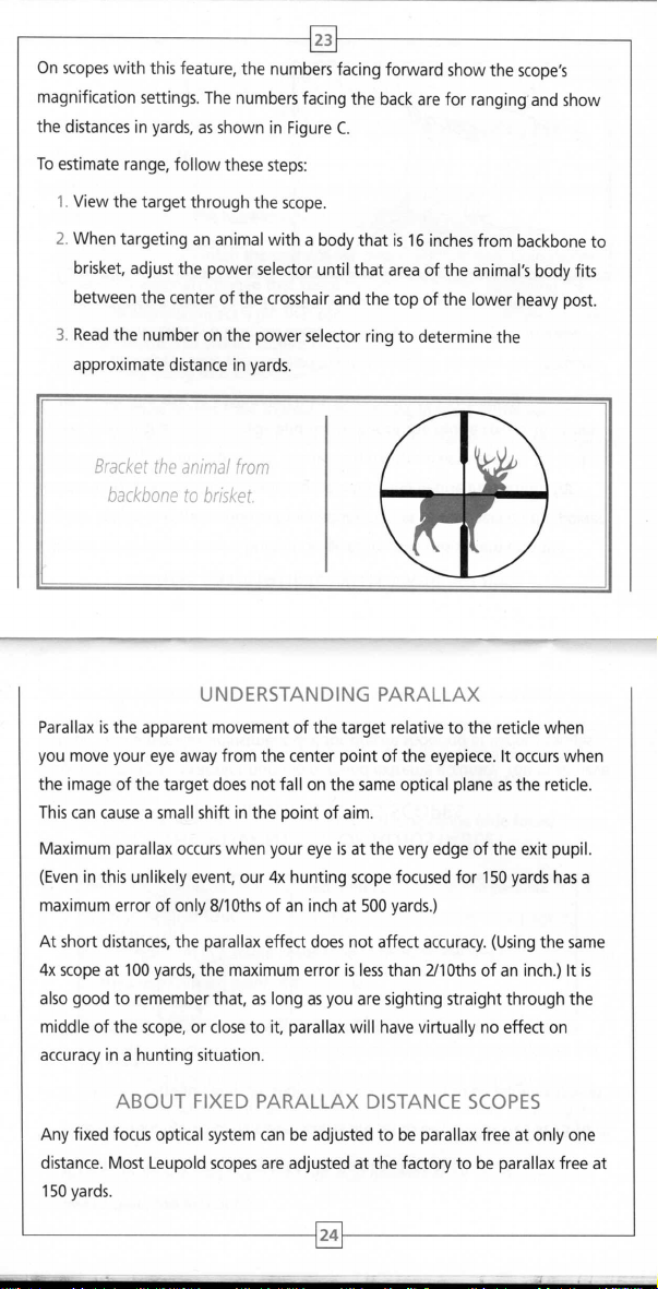
On scopes with this feature, the numbers facing forward show the scope's
~
magnification settings. The numbers facing the back are for ranging and show
the distances in yards, as shown in Figure C.
To estimate range, follow these steps:
1. View the target through the scope.
2. When targeting an animal with a body that is 16 inches from backbone to
brisket, adjust the power selector until that area of the animal's body fits
between the center of the crosshair and the top of the lower heavy post.
3. Read the number on the power selector ring to determine the
approximate distance in yards.
Bracket the animal from
backbone to brisket
UNDERSTANDING PARALLAX
Parallax is the apparent movement of the target relative to the reticle when
you move your eye away from the center point of the eyepiece. It occurs when
the image of the target does not fall on the same optical plane as the reticle.
This can cause a small shift in the point of aim.
Maximum parallax occurs when your eye is at the very edge of the exit pupil.
(Even in this unlikely event, our 4x hunting scope focused for 150 yards has a
maximum error of only 8/10ths of an inch at 500 yards.)
At short distances, the parallax effect does not affect accuracy. (Using the same
4x scope at 100 yards, the maximum error is less than 211Oths of an inch.) It is
also good to remember that, as long as you are sighting straight through the
middle of the scope, or close to it, parallax will have virtually no effect on
accuracy in a hunting situation.
ABOUT FIXED PARALLAX DISTANCE SCOPES
Any fixed focus optical system can be adjusted to be parallax free at only one
distance. Most Leupold scopes are adjusted at the factory to be parallax free at
150 yards.
24
Page 15

25
However, there are exceptions:
1. Leupold rimfire scopes are set to be parallax free at 60 yards.
2. Leupold shotgunlmuzzleloader scopes are set to be parallax free at 75 yards.
3. Leupold Handgun and Ultralight 2.5x scopes are set to be parallax free at
100 yards.
Side Parallax Adjustment
THE ADVANTAGE OF ADJUSTABLE
PARALLAX SETTING SCOPES
Target shooting and varmint hunting demand extreme accuracy. You must have
a scope with a parallax adjustment dial for precise shooting at various ranges.
The parallax adjustment can be located either at the objective end of the scope
or on the side of the adjustment turret housing. The adjustment moves a lens
within the scope causing the target image and the reticle to fall on the same
optical plane. This ensures optimal accuracy at the distance of the target.
To eliminate parallax in adjustable objective and long range (side focus) scopes,
follow these steps:
1. The reticle should be clear (focused) before adjusting the parallax. If it is
not, follow the instructions under "Focusing the Reticle." See page 8.
2. With the firearm in a stable position, look through the scope, concentrating
on the center aiming point of the reticle.
3. Move your head slightly up and down while turning side parallax or
adjustable objective ring until the reticle does not move in relation to the
target. Using the numbers on the Adjustable Objective ring, you can get
your parallax adjustments close to the proper setting before assuming a
shooting position.
NOTE:
Settings may vary slightly per individual preferences, air temperature, and
atmospheric conditions.
26
Page 16

27
NOTE: The side parallax adjustment knob is not to be used to focus the target
image. If the reticle is first focused and the parallax then properly set, the image
should be clear.
To adjust the parallax distance,
turn the focus ring.
EFR SCOPES AND THE ADJUSTABLE OBJECTIVE
Leupold
EFR
(Extended Focus Range) scopes can eliminate parallax for distances
as short as 10 meters. Unlike conventional adjustable objective scopes, the focus
ring on EFR models rotates more than 3600. It is important to pay special
attention when adjusting these scopes.
1. Turn the focus
piece) until it stops.
2. Turn the focus
tor mark on the bell of the scope.
ring
counterclockwise (when viewing though the eye-
ring
clockwise until the "10m" mark aligns with the indica-
3. From this point, all readings of the focus ring are in numerical order
when the ring is turned clockwise from the shooting position.
4. Adjust the ring as you
would
a standard adjustable objective model.
INSTALLING A LENS ATTACHMENT
Many Leupold scopes offer threaded objective and eyepiece rings to allow
for the attachment of lens covers and a variety of Alumina'. accessories. These
attachments thread directly into the objective or eyepiece rings. Turn until
finger tight
do not over
-
tighten.
28
Page 17

29
Using the Illuminated Reticle
All Leupold Illuminated Reticle scopes may be used in either the standard or
the illuminated state. When not illuminated, the reticle performs the same as
the reticle in a standard Leupold scope. Illuminating the reticle allows a better
distinction to be made in poorly lighted conditions between the target and the
precise position of the aiming point.
The control dial for the Leupold
Illuminated Reticle is located
above the eyepiece.
To illuminate the reticle:
1. Grasp the illumination dial located at the top of the eyepiece shell.
2. Turn the dial clockwise from the OFF position to the first number indicated
on the dial.
3. View the target through the scope to determine if the reticle is bright
enough to stand out clearly against the target.
4. If more illumination is required, continue turning the dial clockwise until
the reticle is clearly visible against the target.
To preserve the life of the battery, always remember to turn the illumination dial
to the OFF position when the scope is not in use. For prolonged storage, remove
the battery.
If the reticle fails to illuminate or appears dim even on the highest illumination
setting, it is necessary to change the battery.
WARNING: Always check to ensure that the firearm is unloaded before
changing the battery in the scope.
30
Page 18

31
Changing the Battery
All Leupold Illuminated Reticle scopes use a 3-volt lithium photo battery.
See page 32.
To change the battery:
1. Remove the battery cover by grasping its edge (located around the top of
the illumination dial) and twisting the cover counterclockwise while holding
the sides of the illumination dial to keep the entire dial from turning.
2. Remove the old battery from its position in the center of the dial.
Battery
The battery for the
(()u
This
can be done in two ways:
Leupold Illuminated Reticle
is located inside the
control dial and can be
changed without tools.
a. Grasp the edges of the battery between the thumb and forefinger
and lift it free of the dial.
OR
b. Turn the scope so that the illumination dial faces downward and
gently tap the eyepiece against the edge of your palm.
3. Insert the new battery, positive (+) side up.
4. Replace the battery cover on the illumination dial and turn it clockwise
until it is secure while holding the sides of the illumination dial to keep
the entire dial from turning.
Replacement 3-volt lithium batteries:
Varta.
Ouracetr
Eveready!.
Kodak.
There
may be other lithium batteries that are acceptable with your Leupold
Illuminated Reticle scope. Check with your local retailer for other options.
. . . . . . . . . .
. . . . . . . . .
. . . . . . . . . . .
OLl/3N
2L76
K58L
32
. . . . . . . . . . . . CR
Sanyo. CR 1/3N
1/3N
Page 19

33
Leupold Means Minimal Maintenance
LENSES
Leupold scope lenses are coated to reduce light reflections and light scattering
thus increasing light transmission through the scope. They should be cleaned as
carefully as you would a camera lens. Begin by using a lens brush to remove dust
and then pure alcohol, high-grade glass cleaner, or pure water on a cotton swab.
WINDAGE / ELEVATION ADJUSTMENTS
These adjustments are permanently lubricated. There is no need to lubricate
them. Keep the turret caps on, except when adjusting, to keep out dust and
dirt. (It's worth noting that, unlike competitive brands, Leupold scopes are
waterproof even without the caps in place.)
EYEPIECE ADJUSTMENT
This adjustment is permanently lubricated. There is no need to lubricate it. The
eyepiece can be rotated as far as it will go in either direction. It will not detach
from the scope because of an internal lock ring.
SEALS
Leupold scopes are sealed from within by several methods, including O-rings.
All seals are permanent and require no maintenance.
SCOPE EXTERIOR
Leupold scopes are made of rugged 6061-T6 aircraft aluminum alloy. No
maintenance of any kind is required; simply wipe off any dirt or fingerprints
that accumulate with a clean, dry cloth.
POWER SELECTOR RING (ON VARIABLE POWER SCOPES)
No lubrication is ever required on the power selector ring. DO NOT LOOSEN OR
REMOVE THE HEX-HEAD SCREW IN THE POWER SELECTOR RING.
ADJUSTABLE OBJECTIVE/SIDE PARALLAX DIAL
No lubrication is required.
34
Page 20

35
TROUBLE SHOOTING TIPS
Before you ship a scope back to the factory for service or repair, please check
the following items to make sure that the problem is really with the scope and
not the rifle or mount system.
1. Check the mount. Make sure the scope is mounteu securely to the
rifle. Try, with bare hands only, to twist the scope in the rings or see if
anything moves when you jiggle it. If there is any movement, retighten
the mounting system according to mounting instructions.
2. Make sure the action of your rifle is properly bedded in the stock, and
that all receiver screws are tight and have been tightened in the sequence
recommended by the manufacturer. A loosely fitted stock can cause
changes to the point-of-impact.
3. When test firing a rifle to check the point-of-impact relative to
windage and elevation adjustments, be sure to fire from a solid bench
with sandbags supporting the forearm and buttstock.
4. Be sure to use factory-loaded ammunition of the same bullet type,weight,
and preferably, lot number. If one type of ammunition does not shoot
well, try another brand or bullet weight.
5. Be certain that both the barrel and chamber are clean. Heavy factory
grease on a new rifle and copper fouling on an older one can diminish
the accuracy of the firearm.
Leupold Technical Service
If your Leupold Golden Ring scope fails to perform in any way, you may return
it directly to the factory (or one of our international service centers) for service.
It is not necessary for your dealer to ship the scope to Leupold; however, they
can be very helpful in determining if factory service is necessary. Please follow
these shipping instructions:
1. Remove the rings and any other accessories from the scope.
2. Record the serial number of the scope and keep it for your records.
3. Include a note with your name, address, telephone number, E-mail, and
a description of the problem.
4. Pack the scope in its original box (if you have it), as this is the safest
shipping container. Wrap the package securely using filament strapping
tape on the outside.
5. Ship the scope by parcel or mail service (insured, if possible) to one of the
following addresses:
36
Page 21

37
In the United States:
Parcel Service:
leupold Technical Service
14400 NW Greenbrier Parkway
Beaverton,
USA
OR
97006-5790
By Mail:
Leupold Technical Service
PO. Box 688
Beaverton,
OR
97075-0688
USA
Outside the United States:
Canada: Jim Korth Agencies Ltd., 103 Stockton Point, Box 490
Okotoks, AB TOl lTO, Canada
Germany: Harold Ros, Coburger Strasse 71, 98673 Eisfeld, Germany
Sweden: HDF Gyttorp Jakt AB, Svarvaregatan 5, S-302 50 Halmstad, Sweden
Our
Technical Service telephone number is
(503)
352-7621. They can also be contacted through our Web site at
www.leupold.com.
(503)
526-1400, fax is
The Best Consumer
Protection in the Business
All leupold Golden Ring products are made with your absolute satisfaction in
mind. That's why we offer the leupold Full lifetime Guarantee:
If any Leupold Golden Ring product is
workmanship, we will, at our option, repair or replace it. Free. Even if you are
not the original owner. No warranty card required. No time limit applies.
The leupold Guarantee in Germany and other countries where legally
prohibited: leupold is convinced of the high-quality and reliability of its Golden
Ring products. This is why each U.S. customer is afforded a lifetime guarantee.
For legal reasons, this guarantee must be restricted to 30 years in Germany and
other countries where an unlimited lifetime guarantee is prohibited. Each
owner, even those that acquired a Golden Ring product used, can make use of
this 30 year guarantee.
found
to have defects in materials or
38
Page 22

39
THE LEUPOLD ELECTRONIC WARRANTY
Certain Leupold scopes are equiped with electronic components, which operate
independently of the mechanical and optical systems of the scopes. These
electronic components are warranted for a full two years against all material and
manufacturing defects. This warranty is effective from the date of purchase of the
scope. If, within the course of normal usage, the electronic components of any
Leupold scope malfunction within this period, we will, at our option, repair or
replace it.
LEUPOLD MAKES MORE THAN SCOPES
See our complete line of mounting systems, binoculars, spotting scopes, and
accessories at your nearest Leupold dealer.
For a free Leupold catalog, write to: Leupold & Stevens, Inc., P.O. Box 688,
Beaverton, OR 97075, call (503) 526-1400, or send us an E-mail through
our Web site at www.leupold.com.
The
Leupold
packageis made in part from recycled materials and is 100%
recyclable, This includes the black polypropylene supports, which are made
of an accepted recyclable material, Many Leupold owners keep their scope
boxes If you have no use for yours, we encourage you to dispose of it
responsibly The special cloth surrounding your new scope was designed to
be reusable; consider making it part of your regular gun care kit,
Leupold
& Stevens, Inc. reselVes all other rights. AMERICA'S OPTICS AUTHORITY; CQff; DESIGN ONLY (GOLDEN
RING); DUPLEX; GOLDEN RING; L AND DESIGN; LEUPOLD; LPS; MARK 4;
THE INSIDE; SCOPESMITH; THE HUNTER'S CLOSET; VARI-X; VX; and WIND RIVER are registered trademarks of
Leupold & Stevens, Inc., Beaverton, Oregon, ADVANCED IMAGE OPTlMIZATION; ALUMINA; BALLISTIC AIMING
SYSTEM; BLACK RING; BOONE AND CROCKETT; BZ; CASCADES; FX; GREEN RING DESIGN; GREEN RING; INDEX
MATCHED LENS SYSTEM; INTENSIFIER; KATMAI; L-COAT; LRff; MESA; MRff; OG; OLYMPIC; OP; OPTlMIZER;
PINNACLES; QUICK RELEASE; RAINCOTE; RiflEMAN; SEQUOIA; X-TREME; AND YL are trademarks of Leupold &
Stevens, Inc., Beaverton, Oregon. Note: We re5elVe the right to make design and/or material modifications without
MULTlCOAT 4;
PERFORMANCE STARTS ON
prior notice.
Leupold products are manufactured under one or more of the following patents: U.s, Patents: 4,643,54Z;
5,035,487; 5,Z31,535; 5,671,088; 5,866,048; 6,005,711; 6,Z79,Z59; 6,Z95,754; 6,351,907; 6,359,418;
6,469,8Z9; 6,519,890; 6,816,305; D347,441; D413,153; D414,835; D415,546; D416,97Z; D4Z0,718; D4Z0,807;
D4Z1,Z86; D4Z7,658; D490,097.
Foreign Patents: BX30938-00; CA-Rd./Enr.1999-8847Z; CA 1 Z53381;
DE49903766,9; DE69Z167613; DE-M9304093,8; EP0540368; GB0540368; 1l31338; 1T75604; JP10746Z3;
SE55Z01; TW148948,
This publication may not be reprinted or othelVVise reproduced without the expressed written consent of Leupold
& Stevens, Inc. Copyright
@
ZOOS Leupold & Stevens, Inc. All rights reselVed.
40
Page 23

41
Fral/fais
VEUlllEZ LIRE CE MANUEL EN ENTlER AVANT DE MONTER VOTRE OBJECTIF.
- Mise en garde -
verifiez toujours et dssureZ-VOU5 que f'arme a feu soit dechargee avant d'entreprendre tout travail sur f'arme.
A cause des considi<ations de
aussi loin que possible vers I'avant. Su~z aussi les etapes suivantes :
1. Ave< I'objeaif aussi loin que possible vers I'avant des montur~ tenez la carabine dans votre position normale de tir.
2. Deplacez lentement I'objectif vers I'arriere
1 Placez votre objectif ici pour une position de l'oeil maximale.
4. Passez
REMARQUE : pour con firmer que votre objectif est monte'; la meilleure position possible, essayez plusieurs
positions:
rypiquement Ia position de l'oeil.
Si un
en amont augmente aussi ee danger car cefa reduit la distance entre Ie front et /'arriere de /'objectif. Pour cette
raison, les objectifs Leupold sont aussi fabriques pour offrir une bonne position de l'oeil. Done, en montant votre
objectif, nous recommandons de Ie placer aussi loin que possible
celte generetJSe position de l'oeil.
1. lans d,placer la position de l'oeil optimale, tournez I'objectl! jU"lu'; ce que Ie cadran d'ajustement d'ilevatlOl1 soit au sommet
2. D'une
3. lorsque vous avez ce que vous recherchez, resserrez bien les vis de I'anneau uniformeme-nt.
REMARQUE: pour proteger I'integnte du joint etanche de tout objectd Leupold Golden Ring, un mecanisme
interne emp{>che
ETABLISSEMENT DE LA POSITION DE l'OEil POUR lES CARABINES ET FUSllS
skur;t'
aSlOCiees; la bonne position de l'oeil, Leupold re<ommande !or1ement de monte! votre objecti!
(les objeaifs a grossissement variable devraient etre places a la valeur de grossissement la plus elevee pour cene demarche.)
;
TERMINER L'INSTALlATION.
a genoux,
assis, accroupi et en visant en amont et en ava/. Rappefez-vous que viser
objectif
est monte tres loin vers /'arriere, f'ocufaire de visee pourrait bfesser Ie front du tireur. Tirer dans un angle
jusqu'[;j
ce que vous voyiez un champ de visee complet.
Avertissement -
-
en amont reduit
",rs I'avant dans les montures pour tirer profit de
TERMINER l'INSTAlLATION
de I'object".
position de tir, verifiez pour vous assurer que Ie fil vertical du reticule s'aligne avec I'axe vertical de I'arme a feu. Un mauvais
alignement n'affectera
pas I'exactitude a des distances moderees, mais pourrait reduire I'exactitude de grande portee.
I'omlaire de 50 separer de I'objecti!.
Installez bien I'objecti! et I'arme
Quatre pouces de votre oeil, Ie reticule devrait etre pre<:is et net; si tel n'est
Ii votre objecti! Leupold est
I, Agrippez
Ie sens horaire en I'eloignant de I'oculaire pour qu'il n'entrave
2. 5i vous avez I'habitude de tenir les choses loin de vous-meme pour voir clairement (vous etes hypermetrope). tournez I'oculaire
dans Ie sens antihoraire de quelques tours. 5i vous tenez les choses pres de vous.meme pour les voir clairement (vous etes
tournez I'oculaire dans Ie sens horaire de quelques tours.
3. R~ardez par I'objectif pointe vers Ie del et jetez un coup
differeme du point de depart. Continuez cene procedure jusqu'a ce que Ie reticule semble clair et precis.
4 Lorsque yous etes satisfaJt de !'image du reticule, tournez I'anneau de verrouil1age pour
;
feu dans un appoi ferme. Pointez I'objecti! vers un objet; I'arri,re-plan pale. Ave< I'object;!;environ
de nos modiles a oculaire;anneau de verrouillage, suivez ces 'tapes
I'un
I'oculaire de la main et rerulez de I'anneau de verrouillage.Lorsque I'anneau est d~age de I'oculaire, touroez-Ie dans
MISE AU POINT DU RETICULE
pas Ie cas, il faut ajuster la mise au point ave< I'oculaire.
pas I'ajustement.
d'oeil au reticule. La mise au point du reticule devrait etre vraiment
Qu'il
simples :
myope),
repose fermement contre I'oculaire.
ETABLIR DES AJUSTEMENTS PRECIS DE DERIVE ET D'ELEVATION
le style d'ajustement d'elevation et de derive sur les armes a objectifs Leupold varie selon les modeles. Chacun est clairemem marque en
increments faci!es a lire. Si, par exemple, ilya quatre symboles de numero de zero a
alors la valeur de chaque incr,ment d'ajustemenl sur ce bouton esl de 114-
Leupold. Un MOA d'place Ie point d'impacr; 100 verges par pouce. A 100 metres, il se diplace de 29 mm.
Les lerues qui se UOINent sur les cadrans d'ilevanon et de dirive portent sur ~ direction de d,placement du point d'impacr de ~ balle Iors
(y
compris) Ie chiffre un sur un bouton d'ajustement,
MOA.
('est la m,me chose pour taus les cadrans d'ajustement
d'un ajustement.
Tous les objectifs Leupold comprennent des cadrans d'ajustement pouvam etre repositionnes pour aligner Ie zero du cadran avec
l'indicateur de position sans modifier Ie reglage d'ajustement de I'objectif etabli lors du zerotage. Ced permet au tireur de connaitre Ie
zero original de la carabine
Pour repositionner les cadrans des modeles Rifleman"',
cadran numerate et tournez-Ie pour que Ie zero s'aligne ave< la marque de I'indicateur a ligne etampee sur Ie dessus de la vis d'ajustement
perpendiculaire a la feme de monnaie.
REMISE A ZERO DES CADRANS DE DERIVE ET D'ELEVATION APRES lE ZEROTAGE
doit effectuer d'autres ajustements sur Ie terrain.
s'il
placez une piece de monnaie au un tournevis dans la fente du
-I, et
FX"'-I,
VX'"
42
Page 24

43
les modeles VX.II et FX-II ont un cadran a fleche qui se deplace avec la fente d'ajustement. Ce cadran peut aussi se deplacer
independamment pour s'aligner ave<: Ie zero du cadran exterieur. Pour repositionner ce cadran, tournez-Ie tout simplement jusqu'a ce que
la fleche s'aligne avec Ie zero.
les modeles VX-III et Fx.m ant un cadran indicateur qui peut se deplacer indepe:ndamment pour s'aligner avec Ie zero du cadran
d'ajustement. Pour repositionner ce cadran, tournez.le tout simplement jusqu'a ce que I'eflcoche d'indication de position s'aligne ave< Ie
zero du cadran d'ajustement.
Pour repositlonn" les cadrans des modeles
1. Agrippezle bard du cadran et tirez vers Ie haut.le cadran se sou!evera et tournera librement.
2. Repositionnez
3. Enfoncez Ie cadran et il s'endiquettera en position.
Pour repositionner les cadrans des modeles Target et Tactical:
1.
2. Deplacez Ie cadran du barillet a la main pour aligner Ie lero avec la marque blanche perpendlrulaire a la base du barillet.
3. Resserrez les vis de reglage jusqu'a ce que Ie barillet soit fh.e solidement.
CENTRER LES AJUSTEMENTS DE DERIVE ET D'ELEVATION POUR OBTENIR UN DEPLACEMENT OPTIMAL
les ajustements de derive et d'e!evation deplacent tout Ie systeme erecteur horizontalement et venicalement a I'interieur de I'objectif. Si Ie
systeme erecteur est deplace
deplacement egal dans toutes les directions. Pour retrOllVer un deplacement complet equilibre, vous devez recentrer I'ajustement comme
SUIt:
2
3. Ramenez Ie cadran a la moit;e des dies ou marques de numero comptes precedemment.
4. Repetez celte demarche pour I'ajustement d'elevation.
Ie lerO
Desseml
les ~s de reglage qui entourent Ie dessu, du bouton jusqu"a ce que Ie barillet toumelibrement.
1. Tournez I'ajustement de derive jusqu'a ce qu'il cesse d'avancer.
(omptez les
dies
ou les marques de numero et tournez jusqu'au bout dans I'autre direction.
Lps.
:
sur Ie cadran pour qu'il s'aligne avec la marque iodicatrice sur 1'0bjectJf.
cote, suite a un montage sur une monture non reglable, les ajustements oe permettront pas de
d'un
Tous les objectifs a reticule e<:laire Leupold peuvent servir en mode courant ou e<:laire.lorsque I'appareil n'est
meme r61e qu'un reticule d'obje<tif standard leupold. ~dairer Ie reticule permet de mieux distinguer dans des conditions de mauvais
edairage entre la able et la position precise du point cible.
Pour eclairer Ie reticule.
1. Agrippez Ie cadran d'edairage sur Ie dessus du corps de I'oculaire.
2. Tournez Ie cadran dans Ie sens horaire de la position« OFF» au premier chiffre sur Ie cadran.
3. Regardez la cible par
4
faut plus d'edairage, cootinuez a tourner Ie cadran dans Ie sens horaire jusqu'a ce que Ie reticule soit bien visible contre
S'il
la cible.
Pour conserver la pile, rappelez-vous toujours d'eteindre Ie cadran d'edairage en Ie pla~ant a la positioo« OFF» si vous n'utilisez pas
I'objectif. Pour un rangement assez long, retirez la pile.
Si Ie reticule ne s'allume
Wrifiez toujours fXJur vous assurer que
Ii votre objectlf Leupold Golden Ring connait quelque delaillance que ce soil vous pouvel Ie
nos centres internatiooaux) pour Ie service. II
etre utile pour determiner
1. Retirez lesanneaux et tous !es autres accessoires de I'objectif.
2. Enregistrez Ie numero de serie de I'objectif et conservez-le pour vos dossiers.
3. Ajoutez une note avec votre nom, votre adresse, vetre numero de telephooe, votre courriel et une descriptioo du probleme.
~ Emballel robjectif dans sa boite originalel,; vous ravez) car ceO est Ie contenant d'expedition Ie plus sUr. Emballel bien Ie paquet
a raide d.un ruban feuillard a filament a rexterieuf.
I. Expediel I.objectll par
I'objectif pour determiner si Ie reticule est assez clair pour ressonir dailement par rappon a la cible.
pas ou semble faible meme en choisissant Ie reglage Ie plus elevee, il faut changer la pile.
faut un service en usine. Veuillez suivre
s'il
messag"ie ou par service postal (assure. si pos.blel a rune des adresses su~antes
UTILISER LE RETICULE ECLAIRE
- Avertissement -
/'arme if feu soit dechargee avant de changer fa pile de /'objectif.
SERVICE TECHNIQUE LEUPOLD
pas ne<:essaire que votre coocessionnaire expedie I'objectif a leupold, mais il peut vous
n'est
directives d'expedition :
CE'$
retoum"
pas e<:laire, Ie reticule joue Ie
dITectement a rusinelou a run de
:
44
Page 25

45
Aux Etats-Unis :
Service de messagerie:
Leupold Technical lervice
14400 NW Greenbrier Parkway
Beave~on, OR 97006-1790
UIA
A I'exterieur des Etats-Unis :
Canada: Jim Korth Agencies Ltd., 103 Itockton Point, Box 490 Okotokl, AB TOL 110, Canada
Allemag",: Harold Rol, Coburger Itralle 71, 98673 Eil/eld, Allemagne
.
HOF Gynorp Jakt AB, Ivarvaregatan 5,
luede
Le numero de telephone de notre lervice technique elt Ie (503) 526-1400, Ie fax elt Ie (5031352-7621. VOUI pouvezaulli leI
contacter sur notre site Web a www.leupold.com.
1-302 50 Halmltad, 5uede
Poste
Leupold Technical lervice
P.O. Box 688
Beaverton, OR 97075-0688
UIA
y
mira para evitar la
Espanol
lE SUGERIMOS lEER LA TOTAl/DAD DEL MANUAL ANTES DE INSTALAR LA MIRA TElESC6PICA-
Siempre verifique
Debido las consideraciones de seguridad asociadas (on
fatiga ocular, Leupold recomienda enfaticamente la instalaci6n de la mira te1esc6pica 10 mas adelante posible en el arma. Ademas de 10
anterior, siga
1. Con la mira telesc6pica en la posicion mas avanzada posible sabre la base de montaje, sujele el rifle en la posicion normal de tiro.
2. Desplace lentamente la mira telescopica hacia atras justo hasta obtener un campo visual completo.
3. Coloque la mira telescopica aqui para reducir al minima la fatiga ocular.
4. Pase a TERMINAR LA INITALACION.
NOTA: Para confirmar que su mira telescopica esta instalada en la mejor posicion posible, pruebe varias posiciones:
de rodiflas, sentado, tendidoyapuntando con angulo ascendente 0 descendente. No se olvide que al apuntar con
un angulo ascendente normalmente se reduce la fatiga ocular.
Si una mira telescopica se coloca demasiada atras, el visor puede fesionar la ceja del tiradar. AI disparar en angulo
ascendente tambien se aumenta este riesgo porque se reduce fa distancia entre fa ceja
telescopica. Por este motivo, las miras telescopicas Leupold estan disenadas para evitar al maxima la fatiga ocular. Por
10 tanto, al instalar su mira telescopica, Ie recamendamos colocarla en la posicion mas adelantada posible sabre la
base de montaje a fin de aprovechar al maxima esta'ventaja practica para fa reduccion de la fatiga ocular.
y
weiDrese de que eI arma de fuego este descargada antes de reafizar rrabajo alguno en dieha arma.
C6MO ESTABlECER LA DISTANCIA A LA MIRA TElESc6PICA PARA EVITAR LA FATIGA
pasos:
E'Stos
(Para este proceso se recomienda ajustar las miras telescopicas de amplificacion variable en la maxima posicion de aumento).
OCULAR DURANTE El usa DE RIFlES Y ESCOPETAS
- Precaucion -
las tknicas utilizadas para establ~er la separacion entre aja
Advertencia
-
-
y
fa parte posterior de la mira
PARA TERMINAR LA INSTALACI6N
1. Sin perturbar la posicion optima para evitar la fatiga visual, gire la mira telescopica hasta que el cuadrante de ajuste
de elevacion se encuentre en la parte superior de la mira telescopica.
2. Desde una posicion de tiro, verifique que la linea vertical de la reticula este alineada con el eje vertical del arma de fuego.
la desalineacion no afectara la exactitud a distancias moderadas pero
puedE:' reducir la precision de largo akance.
46
Page 26

3. (uando la alineaci6n sea de su satisfacci6n, apriete 105 tornillos de manera uniforme
47
NOTA A fin de proreger la inregridad del seflo hermerico de cada mira relescopica Leupold Golden Ring,
se dispone de un mecanismo inrerno que impide que el ocular se caiga de la mira te/escopica
Fije la mira telescopic3
a aproximadamente a cuatro pulgadas de su ajD, la reticula debe aparecer nitida
enfoque por media del ocular.
Si su mira Leupold es uno de nuestrQS modelos can un ocular que viene con un anillo de sujeci6n, siga estos pasos sencillos:
I. Sujete el ocular con la manayretrocedalo para desprenderlo del anillo de sujeci6n. Despues que el anillo de sujecion este libre
2. Si usted tiende a alejar los objetos para verlos con mayor claridad (hipermetropia) gire a la izquierda el ocular un par de vueltas.
3. AI ver a traves de la mira telescopica cuando esta apunta hacia las nubes, de unos vistazos a la reticula. EI enfoque de la reticula
4. Cuando la imagen de la reticula sea satisfactoria, gire el anillo de sujecion de manera que este se apoye firmemente contra
y
el arma de fuego en un apoyo firme. Apunte la mira telescopic3 a un objeto con fondo de color claro. Con la mira
del ocular, girelo a la derecha para alejarlo del ocularyapanarlo durante el ajuste.
Si usted liende a acercar los objetos para verlos con mayor claridad (miopia) gire a la der&ha el ocular un par de vueltas.
debe ser considerablemente diferente al que tenia cuando comenzo. Continue este proceso hasta que la reticula aparezca
claraynitida.
elocular.
COMO ENFOCAR LA RETiCULA
y
segura.
y
bien definida; de 10 (ontrario, sera necesario ajustar el
COMO REALIZAR AJUSTES DE PRECISION POR mcTO DEL VIENTO Y DE ELEVACION
EI estilo de los ajustes de elevacionycorreccion por efectos del viento en las miras lelescopicas Leupold varia con los modelos especificos.
Sin embargo, cada una viene claramente marcada con incrementos de facillectura. Si por ejemplo, hay cuatro marcas de referencia desde
cero hasta el numero uno en una perilla de ajuste (ambos valores inclusive), entonces el valor de cada incremento de ajuste en dicha
perilla es de 1/4 de MOA. Esta convencion es la misma en todos los cuadrantes de ajuste leupold. Una unidad MOA
mueve 1 pulgada el punta de impacto a 100 yardas. 0 bien 29 mm a 100 metros.
Las letras que se encuentran en los cuadrantes de correccion por efecto del viento
desplaza el punto de impacto del proyectil wando se realiza un ajuste.
AJUSTE A CERO DE LOS CUADRANTES DE CORRECCION POR mCTO DEL VIENTO Y
Todas las miras telescopicas Leupold incluyen cuadrantes de ajuste que se pueden volver a colocar para alinear la marca de cero del
cuadrante con el indicador de posicion sin cambiar el ajuste del indicador de posicion de la mira que se logro al apuntar con la mira.Lo
anterior permite al tirador conocer el cero original en el rifle en caso de que sea necesario realizar ajustes adicionales en el campo.
DE ELEVACION DESPUES DE APUNTAR CON LA MIRA
y
de e!evacion se refieren a la dir&cion a la que se
(0
minuto de angulo)
Para volver a colocar los cuadrantes en los modelos Rifleman", VX"'-/,
cuadrante numerado
superior del tornillo de ajuste que es perpendicular a la ranura para la moneda.
Los modelos VX-II
independientemente para alinearse con el cero en el cuadrante mas externo. Para volver a colocar este cuadrante sencillamente girelo
hasta que el apuntador quede alineado con el cero.
Los modelos VX.III
cuadrante de ajuste. Para volver a colocar este cuadrante gire10 simplemente hasta que la muesca indicadora de posicion quede a!ineada
con el cero del cuadrante de ajuste.
Para volver a colocar 105 cuadrantes en los modelos LPS8:
Para volver a colocar los cuadrantes en los modelos Target (de liro al blanco)
La realizacion de ajustes de correccion por efecto del viento
mira te!escopica. Si este sistema esta desviado hacia un lad0-{omo resultado de haberlo instalado sobre una base de montaje no
ajustabl~los ajustes no proporcionaran un desplazamiento igual en todas las dir&ciones. Para r&uperar el desplazamiento completo
equilibrado, sera n&esario volver a centrar el ajuste de la manera siguiente:
y
gire dicho cuadrante de manera que el cero quede alineado con la marca indicadora de linea estampada en la parte
y
FX-If tienen un cuadrante apuntador que se mueve con la ranura de ajuste. EI cuadrante tambien se puede mover
y
FX.III tienen un cuadrante indicador que se puede mover independientemente para alinearse con el cero en el
1. Sujete el borde del cuadrante
2. Vuelva colocar el cero en el cuadrante de manera que quede alineado con la marca indicadora de la mira Ielescopica,
3. Haga presion en el cuadrante para que quede encajado en posicion.
1. Alloje los tornillos prisioneros que rodean la pane superior de la perilla hasta que el cilindro gire libremente.
2. Mueva a mano el cuadrante del cilindro para alinear el cero con la marca blanca perpendicular en la base del cilindro.
3. Apriete los tornillos prisioneros hasta que el cilindro quede seguro.
CENTRADO DE AJUSTES DE CORRECCION POR mCTO DEL VIENTO Y DE ELEVACION PARA LOGRAR
1. Gire el ajuste de correccion por efecto del viento hasta el punto en que este deje de moverse.
2. Contando los
3. Gire el cuadrante de regreso la mitad de la cantidad de
4. Repita este proceso para el ajuste de elevacion.
y
tire del mismo hacia arriba. EI cuadrante Ie
UN DESPLAZAMIENTO DE AJUSTE OPTIMO
~clic~
0 las marcas de referencia, girelo completamente en la otra direccion.
y
coloque una moneda 0 un destornillador en la ranura del
FX"'-I,
.
desenganchara'
y
TactICal (tactico):
y
de elevacion desplaza la totalidad del sistema horizontalyverticalmente en la
~clic.
0 marcas de referencia contadas.
y
girara libremente.
48
y
Page 27

49
C6MO UTILIZAR LA RETICULA ILUMINADA
Todas las miras telescopic3S de Leupold con reticulas iluminadas se pueden utilizar en estado estandar 0 en estado iluminado. AI no estar
iluminada, la reticula funciona de la misma manera que la reticula en una mira telesc6pica Leupold estandar. En condiciones de iluminaci6n
deficiente la iluminacion de la reticula permite diferenciar mejor entre el objetivo
Para iluminarlareticula:
1. Sujete el cuadrante de iluminaci6n ubicado en la parte superior del cuerpo del ocular.
2. Gire a la derecha el cuadrante desde la posicion de apagado (OFF)
3. Observe el objetivo a traves de la mira te[escopica para determinar si la reticula es 10 suficientemente brillante como para
destacarse con claridad con respecto al objetivo.
4. Si se requiere mas iluminacion, continue girando a la derecha el cuadrante hasta que la reticula quede claramente visible
con respecto al objetivo.
Para conservar la vida util de la pila, no se olvide de apagar (OFF)
guardar en almacenamiento prolongado, saque la pila.
Si la reticula no se ilumina 0 aparece opaca aun al seleccionar el maximo valor de iluminaci6n, sera necesario cambiar la pila.
Advertencia
Siempre cereiorese que el
de fuego este descargada antes de cambiar la pila de la mira telescopica
ar"",
-
5ERVICIO TECNICO DE LEUPOLD
Si su mira telescopica Leupold Golden Ring no funciona de la manera esperada, puede devolverla directamente a la fabrica
nuestros centros internacionales de servicio) para su reparacion. No es necesario que su concesionario envie la mira telescopica a Leupold;
sin embargo, ellos pueden ser muy utiles para determinar sl es necesario reparada en fabrica. Le sugerimos atender las siguientes
instruccionesde envfo:
1. Retire los anillos
2. Registre el numero de serie de la mira telescopica
3. Incluya una nota con su nombre, direccion, numero de telefono, correo electronico
4. Empaque la mira telescopica en la caja original (si
bien el paquete con cinta de embalaje reforzada con filamentos en el exterior del paquete.
5. Envie la mira telescopica por servicio de entrega de paquetes 0 de correo (con cobertura de seguro si fuese posible) a una de
lassiguientes direcciones:
En los Estados Unidos:
Servicio de entrega de paquetes:
Leupold Technical Service
14400 NW Greenbrier Parkway
Beavenon, OR 97006-1790
USA
y
otros accesorios de la mira telescopica.
y
conservelo para referencia futura.
aun la conserva), ya que este es el embalaje mas seguro para el envfo. Envuelva
Fuera de los Estados Unidos:
Canada: Jim Ko~h Agencies Ltd., 103 Stockton Point Box 490 Okotok~ AB IOL1I0, Canada
Alemania: Harold Ro~ Coburger Itrasse 71, 98673 Eisfeld, Germany
luecia: HDf Gyttorp Jakt AB, Svarvaregatan I,
Nuestro numero de telefono de lervicio Teenico es el (103)
traves de nuestro sitio Web en www.leupold.com.
1-302 10 Halmstad, Iweden
126-1400, fax: (503) 312-7621. Tambien puede comunicarse con ellos a
y
la posicion exacta del punto de mira.
hasta el primer numer') indicado en el mismo.
el cuadrante iluminado cuando la mira telescopica no este en uso. Para
-
(0
a uno de
y
una descripcion del problema.
Porcorreo:
Leupold Technical Service
P.O. Box 68B
Beave~on, OR 97071-0688
USA
50
Page 28

51
Deutscb
BITTE LESEN SIE DIESES HANDBUCH VOR DEM MONTIEREN DES ZIELfERNROHRS GANZ DURCH.
- Vorsicht -
Stellen Sie vor jeder Handhabung sicher, dass die Waffe entladen ist.
Aus mit dem korrekten Augenabstand verbundenen Sicherheitsgrunden empfiehlt leupold,
mtiglich montieren. Folgen Sie auBerdem diesen Schrinen:
1. Halten Sie Ihr Gewehr mit moglichst weit vorn montiertem Zielfernrohr in Ihrer normalen 5chusshaltung (bei Zielfernrohren mit
2. Bewegen Sie das Zielfernrohr langsam nach hinten, bis Sie ein voiles Blickfeld sehen kennen.
1 Montieren Sie das Zielfernrohr hier, urn den maximalen Augenabstand zu erhalten.
4 fahren
HINWEIS: Urn sicherzustellen, dass Ihr Zielfernrohr in der idea/en Position montiert ist sol/ten Sie mehrere
Steflungen einnehmen: kniend, sitzend, liegend, und nach oben und unten zielend. Denken Sie daran, dass
ein lie/en nach oben den Augenabstand meist verringert.
Wenn das Zielfernrohr zu weit hinten montiert ist, besteht die Gefahr, dass das Okular den Schutzen an der Braue ver-
letlt. Das SchieBen in einem Aufwartswinkel erh6ht diese Gefahr, da dabei de, Abstand zwischen der Braue und dem
Okular des Zielfemrohrs verhirlt wird. Leupold Zielfemrohre sind aus diesem Grund mit groBlugigem Augenabstand.
konzipiert. Leupold empfiehlt, das5 Sie das Zielfernrohr so weit vorne wie magfjch montieren, um aile Vorteile dieses
groBzugigen Augenabstands zu nutzen.
3. Wenn 5ie m;t der EinsteUung zufrieden sind, z;ehen 5ie die Ringschrauben gleichmaBig und sicher fest.
HINWElI: Zum Schutz der wasserfesten Versiegelung des Leupold Golden Ring-Zielfemrohrs verhindert ein
eingebauter Mechanismus das Abliehen des Okulars vom Ziellemrohr
Bringen
einem Abstand
der fall ist, muss der Fokus uber das Okular
Wenn das Okular des leupold-Zielfernrohrs mit einem Feststellring ausgerustet ist. fUhren Sie die folgenden Schritte aus:
I. Greifen Sie das Okular mit der Hand, und ziehen Sie es
2. Wenn Sie dazu neigen, Dinge van sich weg zu halten, urn sie scharf zu sehen (Weitsichtigkeit), drehen Sie das Okular urn ein paar
3.
4. Wenn lie mit dem Absehenbild zufrieden sind, schieben
Die Windabdrih. und Hohenverstellung
leicht erkennbare Stufen unterteilt. Wenn sich beispielsweise van Null bis einschlieBlich Eins auf dem Verstellrad vier Striche befinden,
betragt der Wert jeder
tOO Yards urn 1 Zoll. Auf 100 m wird er urn Z9 mm verschoben.
Die Buehstaben auf der Windabdrilt- und Hohenverstellung verweisen aul die Richtung der Trelfpunktverschiebung
jeweiligen Anpassung.
Aile leupold-Zielfernrohre veriugen uber Einstellungen, die verstellt werden konnen, urn die markierte Nullstellung des Rads an der
Positionsanzeige auszurichten, ohne die beim EinschieBen erzielte Einstellung des Zielfernrohrs zu andern. 50 kennt der Schutze die
ursprungliche Nullstellung des Gewehrs, falls im Feld weitere Justierungen durchgefUhrt werden mussen.
EINSTELLUNG DES AUGENABSTANDS BEl GEWEHREN UND SCHROTfLINTEN
dass
5ie das Zielfernrohr so weit vorne wie
variabler VergroBerung mussen lie hierbei die hoehste VergroBerungseinsteliung wahlen).
lie mit ABICHlUII
DER INITAlLATlDN fort.
Achtung
-
-
ABSCHLUSS DER INSTALLATION
1. Orehen Sie das Zielfernrohr, ohne die ideale Augenabstandsposition zu andern, bis die Hohenverstellungsscheibe sich oben am
Ziellernrohr betindet
yon
2. Prufen Sie
einer Schusshaltung aus, ob die vertikale linie des Absehens mit der vertikalen Achse der Waffe ubereinstimmt. Eine
falsche Ausrichtung hat keinen Einfluss auf die Genauigkeit bei geringen Entfernungen, kann aber die Genauigkeit bei groBen
Entfernungen beeintrachtigen.
lie die Walfe mit dem Ziellernrohr
yon ungelahr 10 em zwischen dem Ziellernrohr und Ihrem Auge sollte das Absehen gestochen schari sein. Wenn dies nicfit
getrenm ist, drehen Sie ihn im Uhrzeigersinn yom
Umdrehungen gegen den Uhrzeigersinn. Wenn
Okular urn ein paar Umdrehungen im Uhrzeigersinn.
Richten lie das Ziellernrohr inden Hjmmel,und prulen lie das Absehen einige
anders sein als zu Beginn. Setzen Sie dieses Verfahren fort, bis das Absehen gestochen scharf ist.
SCHARfSTELLEN DES ABSEHENS
in einen lesten Halt Richten
eingestellt werden.
lie
PRAZISE WINDABDRlfT- UND HOHENVERSTELLUNG
lie das Zielfernrohr aul ein hellfarbiges Hintergrundobjekt Bei
yom Feststellring nach hinten weg. Wenn der Feststellring yom
Okular weg,
sodass er beim Einstellen nicht im Weg ist.
Dinge nohe halten, urn sie schari zu sehen (Kurzsiehtigkeit), drehen
Male.
Dieleharie des Absehens sollte merklieh
lie den feststellring zuruek, sodass dieser fest am Okular anliegt
Okular
lie das
ist bei jedem leupold.Ziellernrohr etwas anders. Die Einstellung ist jedoch bei jedem Modell in
Itule 1/4 Winkelminute. Dies trifft aul aile leupold-Einstellrader zu. Eine Winkelminute verschiebt den Trelfpunkt aul
bei der
JUSTIEREN DER WINDABDRlfT- UND HOHENVERSTELLUNG NACH DEM EINSCHIESSEN
52
Page 29

53
Um die Icheiben an den Modellen Rifleman', VX'.I und fX'.11U verstellen,
Schlitz der Skalenscheibe ein und drehen diese. bis die Null sich an der eingestanzten linie oben auf der Verstellschraube ausrichtet, die
"chtwinklig 10m Munmhlitz steht.
Die Modelle VX.II und fX.1I vertugen uber eine Anzeigeskala, die sich mit dem Einltellschlitz bewegt. Diese Ikala kann auch separat
bewegt werden, um lich an der Null aul der auBeren Icheibe au\Zurichten. Um die Ikala 10 verstellen,
der Null ausgerichtet ilt.
Die Modelle VX.III und fX.1I1 vertugen uber eine Anzeigeskala, die sich mit dem Einltellschlitz bewegt. Diese Ikala kann auch separat
bewegt werden, urn sieh an der Null auf der auBeren Scheibe auszurichten. Urn die Skala zu verstellen, drehen
Anzeigekerbe an der Null ausgerichtet ist.
Verstellung der Icheiben bei LPI'.Modellen:
I Fassen Sie die Kante der Scheibe an und ziehen Sie sie nach oben. Die Scheibe bewegt sich nach oben und ist nun frei drehbar.
2. Drehen Sie die Null auf der Scheibe,
1 Drucken Sie die Scheibe nach unten,
Verstellung der Icheiben bei den Modellen Target und Tactical:
1. LOsen lie die Itellschrauben um den D"hknopf herum, bis sich der lylinder
2. Verschieben Sie die Zylinderskala per Hand. urn die Null an der weiBen senkrechteo linie uoteo am lylioder auslurichteo.
J. liehen lie die Itellschrauben wied.. an, bis d.. lylind.. gesichen ilt.
Die DurchfUhrung von Windabdrift- uod Hoheoverstelluogen verschiebt das gesamte Umkehrsystem ionerhalb des lielfernrohrs horizootal
und vertikal. Wenn das Umkehrsystem seitlich verschoben ist (wegeo Montage auf eioer nicht verstellbaren Befestigung) bietet die
Verstelluog oicht io aile Richtungen den gleicheo Weg. Urn eioeo voll ausgeglichenen Weg luruckzuerhalteo, musseo Sie die Einstellungen
folgendermaBen neu lentrieren:
I.
lie die Windabdriheinltellung bil 10 dem Punkt, wo sie lich nicht mehr bewegt.
D"hen
I.
lie sie voilltandig in die and... Richtung und lahlen lie dabei die Klicks od.. Itrichmarki..ungen.
D"hen
J.
lie die Einstellung um die Halhe d.. gezahlten Klicks od.. Itrichmarki..ungen luruck.
D"hen
4 Wiederholen Sie dieses Verfahreo fUr die Hoheneinstellung.
sodass
sie sich an der Anzeigemarkierung am Zielfernrohr ausrichtet.
sodass
sie einrastet.
ZENTRIEREN DER WINDABDRIFT- UND HOHENVERSTELlUNG
UM EINEN OPTIMALEN EINSTElLWEG ZU ERREICHEN
lie eine Munze oder einen Ichraubenlieher 10 den
fUh"n
lie diese, bis die Anzeige an
d"hen
Sie diese,
I"i d"ht.
bis die
Aile Leupold lielfernroh.. mit beleuchtetem Absehen kbnnen entwed.. im ltandardmodul od.. beleuchtet v..wend.. w..den. 1m nicht
beleuchteten lUltand lunktionien das Absehen genau so wie das Absehen in einem standardmaBigen Leupold liellernrohr. Die
Beleuchtung d~ Absehens erleichtert bei schwierigen lichtverhaltoissen die Unterscheiduog zwischen dem liel uod der prazisen Positioo
deslielpunktl
10 beleuchten lie das Absehen:
1. fassen lie die Beleuchtunglskala an d.. Oberseite des Okulargehauses.
VERWENDUNG DES BElEUCHTETEN ABSEHENS
I.
lie die Ikala im Uhrzeigersinn yon d.. AUlpolition (Off) lor ..sten Numm.. aul d.. Ikala.
D"hen
J. Betrachten lie das liel durch das liellernrohr und prulen lie, ob das Absehen hell genug ist, um yom liel deutlich unt..schieden
zuwerden.
4. Wenn mehr Beleuchtung nbtig ist, d..hen lie die Ikala weit.. im Uhrzeig..sinn, bil das Absehen klar gegen das liel sichtbar ilt.
Um die Lebensdau.. d.. Batt..ielu v..langern, lollten lie die Beleuchtungllkala aul Off Itellen, wenn das liell..nrohr nicht benulZt
wird. Bei laogerer Lagerung ist die Banerie zu entfernen.
Wenn das Absehen nicht aulleuchtet od.. selbst beim hikhlten Beleuchtunglwen blasl erscheint, lOUIS die Batt..ie gewechselt w..den.
- Achtung
Vergewissern Sie sich var dem Wechse/n der Batterie im Zielfernrohr stets, dass die Waffe ent/aden ist.
-
LEUPOLD TECHNISCHER KUNDENDIENST
Wenn die Leistung des Leupold Golden Ring lielfernrohrs in irgendeiner Weise beeinuachtigt ist, konnen Sie es zur Reparatur direkt an das
Werk (oder an ein internationa!es Kundendienstzenuum) senden. Es ist nicht erforderlich, dass der Fachhandler das lielfernrohr an Leupold
sendet. Er kann Ihnen jedoch bei d.. Entscheidung behilflich sein, ob eine W..ksuberarbeitung ertord..lich ist. Bitte beachten lie die 101.
genden Versandanweisungen:
1. Entl..nen lie Ringe und and..es lubehbr
2. Bewahren Sie die Seriennummer des lielfernrohrs auf.
J. Legen lie dem Paket eine Notil mit den lolgenden Inlormationen bei: Name,
Besch"ibung des Probleml.
yom
liellernrohr.
Ad"lse, Telelonnumm.., E.Mail.Ad"sse und
54
Page 30

55
4 Packen lie das lielfernrohr nach Miiglichkeit in die Originalverpackung ein, da dies der sicherste Versandb<halter is! Umwickeln lie
das Paket auBen gut mil Paketklebeband.
I. lenden lie das lielfernrohr per Paketdienst oder Post Iwenn miiglich versichen) an eine der folgenden Adressen:
In den UIA:
Paketdienst
Leupold Technical lervice
14400 NW Greenbrier Parkway
Beavenon, OR 97006-1790
UIA
AuBerhalb der UIA:
Kanada: lim Kanh Agencies Ltd., 103 Itockton Point, Box 490 Okotoks, AB TOL ITO, Kanada
Deutschland: Harold Ros, Coburger ItraBe 71, 98673 Eisfeld, Deutschland
Ichweden: HOF Gyttorp lakl A8, lvarvaregatan I,
Oie Rulnummer unseres technischen Kundendienstes in den UIA lautet (+ 1)
Fax unter der Faxnummer
1)
503 352 7621 bzw. ub<r unsere Website www.leupold.com erreicht werden.
1+
1-301 10 Halmstad, Ichweden
Post:
Leupold Technical lervice
P.O. Box 688
8eavenon, OR 97075-0688
UIA
503 526 1400. Oer technische Kundendienst kann auch per
Italiano
lEGGERE PER INTERO QUESTA GUIOA PRIMA 01 MONTARE Il CANNOCCHIAlE 01 MIRA,
Prima di iniziare quafsiasi lavoro sull'arma da fuoco, controflarla e accertarsi (he sia scarica.
Con riferimento aile considerazioni di sicurezza connesse a una corretta distanza dell'oculare dall'occhio, la Leupold raccomanda
fortemeote di montare it cannocchiale nella posizione pit'! avanzata possibile. Eseguita questa operazione, procedere come
1. Col cannocchiale nella posizione piu avanzata consentita dai supporti, imbracciare it fucile nella propria consueta posizione di sparo
(per questa procedura i cannocchiali a ingrandimento variabile vanno regolati al massimo).
2. Far scorrere lentamente all'indietro il cannocchiale, fermandosi appena il campo visivo e completo.
3. Fissare il cannocchiale in tal punto per avere la massima distanza dell'oculare dall'occhio.
OISTANZA TRA OCULARE E OCCHIO SUI FUCILI
4. COMPlETARE Il MONTAGGIO.
NOTA: Per avere Ja conferma che iI cannocchiaJe e montato nella migJiore posizione possibile, provare ad assumere
posizioni diverse:in ginocchio, sedut/; proni, e puntare sia verso rafto, sia verso if basso. Ricordarsi che quando si
punta verso J'alro di norma si riduce la distanza de/l'ocufare dalf'occhio.
Se if cannocchiale e montato troppo indietro, I'ocufare PUQ ferire Ja fronte del tirarore in corrispondenza delle
sopraccigfia. Quando si spara verso I'alto si aumenta questo pericofo perch€! si diminuisce Ja distanza tra Ja fronte e Ja
parte posteriore del cannocchiale. Per questa ragione,
una notevoJe distanza de/l'occhio dalf'oculare. Raccomandiamo, quindi, quando si monra if cannocchiale, di
posizionarJo sui supporti quanto piu possibile in avanti, in modo da sfruttare al meglio tale caratteristica costruttiva
1. Seoza alterare la distanza ottima!e dell' oculare dall'occhio, ruotare il cannocchiale finche la manopola graduata di regolazione
dell' elevazione e nella pane superiore del cannocchiale.
2. Dalla posizione di sparo, controllare e assicurarsi che I'incisione venicale del reticolo sia allineata con I'asse venicale dell'arma
da fuoco. Un cattivo allineamento non influira sulla precisione a distanze modeste, ma pub diminuire la precisione a lunghe
distanze.
- Attenzione -
- Awertenza -
j
cannocchiafi Leupofd sono progettati in modo da consentire
COMPLETAMENTO DEl MONTAGGIO
s~ue:
56
Page 31

57
3 Quando si e soddisfani, serrare bene Ie viti dei callari in modo uniforme.
NOTA: Per proteggere la tenuta stagna, agni cannocchiale di mira Leupold Golden Ring e munito di un dispositivo
interno che impedisce il distacco dell'oculare dal cannocchiale.
Assicurare il cannocchiale e I'arma da fuoco a un sostegno stabile. Puntare it cannocchiale verso un oggeno (he
chiaro. Col cannocchiale posta a circa 10 em dall'occhio il reticolo dovrebbe apparire nitido e ben ~efinito; se non 10 e, e necessario
regolarela
Se il proprio cannocchiale Leupold e uno dei rnodelli con Deulare munito di ghiera di bloccaggio, seguire questi semplici passi:
a luoco agendo ,ull'oculare.
mel'"
1. Afferrare con la mano I'oculare e tirado indietro per allontanarlo dalla ghiera. Quando la ghiera di bloccaggio e liberata
dall'oculare, girarla in senso oraria, allontanandola dall'oculare, per non ostacolare la regolazione.
2. Se si ha la tendenza ad allontanare Ie cose per vederle chiaramente (presbiopia) ruotare I'oculare in sensa antiorario di un paio
di girL Se invece si tengono Ie cose vicino agli occhi per vederle meglio (miopia) ruotare di un paio di giri
3. Mentre si guarda anraverso il cannocchiale puntato verso il cielo, dare alcune rapide occhiate al reticolo. Ci dovrebbero essere
notevoli differenze nella messa a fuoco del reticolo rispeno a prima. Continuare il procedimento finche il reticolo appare chiaro
e ben delinito.
4. Quando I'immagine del reticolo e soddisfacente, ruotare la ghiera di bloccaggio in modo da farla appoggiare saldamente contro
I'oculare.
MESSA A PUNTO DELLA DEVIAZIONE E DEll'ELEVAZIONE
Le modalita di regolazione dell'elevazione e della deviazione per i cannocchiali di mira Leupold per fucili cambiano a seconda del modeno.
Ogni regolazione e tunavia eseguita con incrementi di facile lenura. Se, per esempio, vi 501'10 quanro tacche da zero a uno (compreso) sulla
manopola di regolazione, il valore di ogni regolazione con quella manopola e pari a 1/4 di minuto d'angolo. ~ la stessa cosa con tune Ie
manopole di regolazioneleupold. Un minuto d'angolo lpolta il punto d'impano di 29 millimeui a 100 meui.
Le lenere suite manopole di regolazione della deviazione e deH'elevazione indicano la direzione in cui si sposta il punto d'impano del
proienile quando si esegue una regolazione.
AZZERAMENTO DELLE MANOPOLE DI DERIVAZIONE E DI ELEVAZIONE DOPO LA TARATURA INIZIALE
Tuni i cannocchiali di mira Leupold dispongono di manopole di regolazione che possono essere riposizionate per allineare 10 zero inciso
sulla manopola con l'indicatore di posizione senza modificare la taratura iniziale del cannocchiale eseguita col metodo del traguardo.
Questo consente al tiratore di ritrovare 10 zero originale del fucile nel casa fosse necessario eseguire successive regolazioni suI campo.
MESSA A FUOCO DEl RETICOLO
abbia uno sfondo di colore
I'oculare in senso orario.
Per riposizionare Ie manopole sui modem Rifleman"', VX" -I. e
numerato e ruotarlo fino ad aHineare 10 zero con la linea di riferimenlo impressa sulla parte superiore deUa vite di regolazione che e
perpendicolare aHa scanalatura per la moneta.
J modelli VX-II e FX-II sana muniti di un quadrante indicatore solida!e con la scanalatura di regolazione. Anche ta!e quadrante pu6 essere
spostato indipendentemente per
I'indicatore e allineato con 10 zero.
1 modelli VX-III e FX-III hanno un quadrante indicatore (he pub ellere lpoltato indlpendentemente per I'allineamento
graduazione di regolazione. Per riposizionarlo e sufficiente ruotarlo finche la tacca indicatrice di posizione non sia allineata con 10 zero della
graduazione di regolazione.
Riposizionamento dei quadranti dei modelti
1 Afferrare il bordo del quadrante e ,ollevarlo. II quadrant' Ii \{)lIevaalcano ed e libero di girare liberamente.
2. Riposizionare 10 zero del quadrante fino ad allinearlo con la tacca indicatrice sui cannocchiale.
3. Premere suI quadrante che scattera in posizione.
Riposizionamento dei quadranti dei modelli Target e Tactical:
1. Allentare i grani situati sulla corona esterna della parte superiore della manopola finche il cilindro ruota liberamente.
2. Spostare a mano il cilindro graduato fino ad allineare 10 zero con la tacca bianca perpendicolare alia base del cilindro.
3. Serrare i grani lino al blo(caggio del (ilindro.
le regolazioni di derivazione e di elevazione spostano l'intero sistema raddrizzatore in senso oriuontale e verticale atrinterno del
cannocchiale. Se il sistema raddrizzatore e spostato su un lato
non produrranno la stessa corsa in tuttiisensi. Per ristabilire una corsa perfettamente equilibrata, occorre ricentrare Ie regolazioni:
1. Ruotare la regolazione di derivazione fino
2. Ruotare completamente in sensa opposto contando gli scatti 0 Ie tacche.
3. Ruotare la manopola in sensa apposta per la meta degli scatti 0 delle tacche contati.
4. Ripetere la procedura per la regolazione dell'elevaziane.
I'allineamento con 10 zero della graduazione esterna. Per riposizionarlo e sufficiente ruotarlo finche
LPS':
CENTRATURA
DEllE
PER OTTEN ERE LA MIGLIORE CORSA DI REGOLAZIONE
FX'" -I: inserire una monela 0 un cacciavile nella scanalatura del quadrante
REGOLAZIONI DI DERIVAZIONE ED ElEVAZIONE
a causa del montaggi~ su un suppono non regalabile -Ie regolazioni
-
arresto.
all'
(on
10 zero della
58
Page 32

59
usa DEL RETICOLO ILLUMINATO
Tuni i cannocchiali di mira Leupold can retjeolo illuminato possono essere usati can 0 senza illuminazione. Quando non e illuminato. il
reticolo si comport3 (orne il reticolo dei cannocchiali standard Leupold. rilluminazione del reticolo consente di distinguere meglio il preciso
punta di mira suI bersaglio in condizioni di luce scarS3.
Per illuminare it reticolo:
1. Afferrare la manopola di illuminazione posta sapra !'involucra dell'oculare.
2. Girare la manopola in sensa oraria dal1a posizione di OFF (spento) al primo numero indicato sui quadrante.
3. Osservare il bersaglio attraverso il cannocchia!e per stabilire se il reticolo e abbastanza luminoso da spiccare chiaramente
sui bersaglio.
4. Se occorre una maggiore illuminazione, continuare a ruotare la rnanopola in senso orario fin quando il relicolo e chiaramente
visibile sui bersaglio.
Per salvaguardare la durata della baneria, ricordarsi di ruotare la rnanopola di iIIuminazione sulla posizione OFF (spento) quando non si usa
il cannocchiale.ln caso di prolungata inattivita, togliere la baneria.
Se il reticolo non si illumina 0 appare debolrnenle illuminato anche al massimo della regolazione, significa che occorre sostituire la baneria.
Prima di SQStituire la batteria del cannocchiale, controflare e accertarsi sempre che I'arrna da Fuoco sia scarica.
SERVIZIO DI ASSISTENZA TECNICA LEUPOLD
Se il cannocchiale di mira Leupold Golden Ring non funziona correnamente, 10 si pu6 restituire direnamente alia fabbrica
centri internazionali di assistenza Leupold) per la riparazione. Non e nffessario rivolgersi al rivenditore per spedirlo alia Leupold, ma si pu6
ricorrere al rivenditore per determinare se e necessario un intervento presso la fabbrica. Istruzioni per la spedizione:
1. Togliere i collari ed eventuali altri accessori dal cannocchiale.
2. Annotare e conservare il nurnero di serie del cannocchiale.
3. Allegare un foglio su cui siano suitti il proprio nome e cognome, indirizzo, numero di telefono, eventuale indirizzo di posta
elettronica e la descrizione del problema.
4. Imballare il cannocchiale nella scalola originale (se la si e conservata) perche e il contenitore di spedizione piu sicuro. Proteggere
bene it pacco awolgendo la parte esterna con nastro adesivo con fili di rinforzo.
5. Spedire il cannocchiale usando un corriere 0 il servizio postale (se possibile, assicurare la spedizione) a uno dei seguenti indirizzi:
Negli USA:
Se si usa un carriere:
leupoldTechnieal Service
14400 NW Greenbrier Parkway
Beavenon, OR 97006-5790
USA
Fuori degli USA:
Canada: Jim Korth Agencies ltd., 103 Stockton Point, Box 490 Okotoks, AB TOlITO, Canada
Germania: Harold Ros, Coburger
Svezia: HDF Gyttorp Jakt AB, Svarvaregatan 5, S.302 50 Halmstad, Svezia
11 numero telefonko del servizio di assistenza negli USA e
1(503)
al numero +
352-7621 0 tramite internet presso il sito www.leupold.com.
Strasl<'
- Avvertenza -
71, 98673 Eisfeld, Germania
1 (503)
526-1400. Si pu6 contattare iI servizio di assistenza anche tramite fax
+
Se si usa iJ servizio postale:
leupoldTechnieal Service
P.O. Box 688
Beaverton, OR 97075.0688
USA
(o
a uno dei
60
Page 33

61
Notes
Notes
62
Page 34

Notes
.:.~it;."';'.':;.
.
,'~~~e~~'~
63
".-.'y ..':\
,
/
.
"..
64
Page 35

,
_= >'J,,
.
.~
.
.j"
,. ., :;.; iJ('{. -,
~
1
j'lJl~ !II
t..
.
I
<1
:401
..".-
~- '"
I
~' If.:~;>
,,<,;.
. .
...
:'-
"'
'. ~(I.~~"
"'!?;', ;D""
.c.,' .-
"', ,,"
!II!g: .iII
\!;:>.c
'
,,
,
1>j.
>~j ri
fj
Ui J.
'
:. r:! ~~.'
'~'''.I)
~
~
~"EI
fj
~OI:
J"
!!
<;P
l:.,
~
& 111'.
.
~ '~, ..,.' '.,
,
.~'. .
-.;'" .'
..
~ ~ ,
""
"'II't'lt
II' ,.~ 'j1c~W ,'iii.:,. !ill
~.. ~ ~.'
{j
r
' ;Ii" 011/
- "-" - -'
.,
'!II,"
""
Y
Car
---"
,\
-
I':iI
~"
:{;
."
. ~..." ,,' ..'
. ,.,
,. 4I,~
';;';
'"
~;'~ ~'!~~V~
.
~I
.
,>«"
.'J r;:;wVi
1<1,;.
rr~
,
~;.
,,~T;
~
.t-'L >:~ II
~
iJ
~ .W
: .
,
,r~,
~
,,;'
.
p
~~Ii
''''i:i!''
,
w
Ie
'
~.
~:~..iit!Mf- ".,~ i:
~
."
~34,;Art" ,39,."
_
..
,
,
~'~,~~.
I"
" "'
1>. :~
.~.
,; .~~,~
'~.~
-
"'''' "'
U
PO
_.
,
.'1'
"
tJ~::.,:,..!i,::
~
.
.t''l ",;
'""
.
"C'"
.~. .~ ,', II
~
.""."'"
.
"°,
.~.."". \'I~"~ If,
,
~ 'iii,
I
d
C
'
,
,
,
..
,,
'!:~)...,
:I
~
°
',
ftiI
-
I,'j )!;
"'.
l!'!!
'"
iii
,
'
.
"" "'~
,,,"" lJ>~
"'
m
c",~ 'i
~
'~
~'
.~.::>. .;.;..(',.ii. ~
'
'
'
'
'
i'i'
.~~ ..
.
._
-
:
,
.
-
'>... ~7'i~, ~~ ,~~r!i~ ~ ~ M- .
~-
~~,
r'
-~
~';\ \'ti..r:
!)
~
~!iI
"
\;
'""
-
~..~
""
~" .- .
1.~
,""
\r
.
~""8
,}",,'
"
%'
!C"
"
,
'''~",..';;t~ ~
e.~ ~
)
~~c~.
~~:tit~,..
",.~
~~. d ~
'ii'
,- . ~!tiII..
.
f.
'~
_
'
CI
..
~
,
" ~'£'!
.
~'~ '~
[!;
~
-,
.,~
' -
" ~
'
'
_.
..
~
15
.
I
'-'II
'
' :
.
.
'~
.
11
iii
'
.
"__,,
..,:,
.-."
'"
 Loading...