

FineTek PT-7610, PT-7650, PT-7620, PT-7630, PT-7640 Operation Manual
...
08-PT76XX-B0-EM, 04/07/2011
FRONT PANEL
DIMENSION / PANEL CUTOUT
un it : (mm)
TEMPERATURE
CONTROLLER
PT-7610 PT-7620 PT-7630
PT-7631
PT-7640
Content of the packaging
Noume non Wa sh er
Bac k co ver U ser ' s ma nua l
Bra cket (2 pcs)
Thank you for please read the User' s manual first before buying
Fine-Tek products and using and is familiar with product
performance and every function, please keep the user' s manual
so that consult in future. Modbus communication can be
downloaded from http: //www.fine-tek.com
SPECIFICATIONS
Power Supply
Power Consumption
Relay
Pulse
(Driven by SSR)
Analog
Con trol Ou tput
Alarm Output
Alarm Delay Time
Alarm Output
Hysteresis Adjustment
Communication
Interface
Working Temperature
Cycle Time of
Output Control
Control Method
Input Compensation
Sampling Time
Accuracy
DC: 2 0~36V dc ※Exce pt PT-76 10
AC: 1 00~24 0Vac 50/ 60Hz
7A Max.
Output:
SPST- 3A/250Vac
(Life Time:100,000 times)
12V dc (NPN ), 20mA Ma x.
4~2 0mA, 0~ 10Vdc ( 600W Ma x.)
SPS T-NO, 3A /250Va c
0~9 9s
0~9 999
RS4 85 Outp ut
0~5 0BC (20 ~85% RH )
0.5 ~999. 9s
ON/ OFF or PI D +Fuzz y(Aut o Tuni ng)
-19 99~99 99
250 m s
0.3 %A1di git
ERROR ME SS AGES
Display over s cale
Display unde r scale
Over measure r ange
Under measur e range
Sensor break
DESCR IPT ION OF PARAME TER S
Control output
hysteresis
Manual reset
PV input filter
Cycle time
Function list
lock
You can set a hysteresis around the set
point to prevent chattering
In PID control, I=0, PV=SV, reset the control
output to " " value
This function should be used the PV display
value may fluctuate greatly,for example, when
the measured input signal contains noise. If a
larger time constant is set, the filter can
remove more noise.
The cycle time is the period of on/off repetitions of a relay
or voltage pulse output in time proportional PID control.
The ratio of the ON time to the cycle time is proportional to
the control output value. If output for the relay, setting has
to be more than 15.
Direction of relay
You can set the mode of function lists which
can be displayed and edited.
PT-7650
PV
1
SV
2
3
4
OUT1
OUT2
ALM
LC
TERMINAL ARRANGEMENT
Please inspect the specification of the power.
Don't connect the end Terminals not used.
Propose that the signal line uses AWG 18~24
to enclose the isolate wire, the main power
cable and relay export the contact and use
AWG 25~30.
6
e
e
F
l
n
k
T
7
8
5
Process value,and functions display.
1
(Red 7-segment)
Setting value,and parameters display.
2
(Green 7-segment)
Control output indicator
3
Alarm indicator.
4
Unit indicator Lighted:BC Unlighted:BF.
5
"Up" key: addition and mode change.
6
"Shift" key: position shift.
7
"Enter" key: confirmation.
8
1. Really lock the end Terminals screw, if the screw has not been locked but
lost by causing the fire or mechanical breakdown.
2. Please don't be using this product and having places where we can fire
gas, cause the risk of exploding by the fact that it may.
3. The life-span of the relay must depend on the user's usage, the use of
the relay must be in specified load and life-span of electric apparatus that
it labels, if the use of the relay exceeds its life-span, the danger that may
melt or cause the fire in the contact of the relay.
4. Don't disassemble, repair or revise the products without authorization,
this measure may cause the short circuit of the electric apparatus,
trouble or fire.
5. Don't drop inside products by chip or chip of wire metal, will cause the
short circuit and account or fire.
Please strictly observe the following instructions, it can
guarantee this safe operation in anticipated cases of
controller:
Use the product within the ratings specified for submerging in water and
exposure to oil.
Do not use the product in locations subject to vibrations or shocks. Using
the product in such locations over a long period may result in damage
due to stress.
Do not use the product in locations subject to dust, corrosive gasses, or
direct sunlight.
Separate the input signal devices, input signal cables, and the product
from the source of noise or high-tension cables producing noise.
Separate the product from the source of static electricity when using the
product in an environment where a large amount of static electricity is
produced (e.g., Forming compounds, powders, of fluid materials being
transported by pipe).
Organic solvents (such as pain thinner), as well as very acidic or basic
solutions might damage the outer casing of the Temperature controller.
Store at the specified temperature. If the Temperature controller has
been stored at a temperature of less than -10BC, allow the Counter to
stand at room temperature for at least 3 hours before use.
Wait 30 minutes after power on before calibration
LOCK LOCKLOCK
.
PT-7 610 48m m(W)x 24mm( H)x98 .5mm( D)
48
OUT
BC
BF
ALM
24
24
Main
Item
Data Range
Sub Item Default Value Describe
OFF~2
0
0
-1999~9999
0
0000~9999
00 SEC
00~99
+0.6
-0
Relay out put
4
3
48
e
e
F
l
n
T
k
58 min .
+0.8
-0
NO
RTD
ALM
7 8 9 10 11 12
1 2 3 4 5 6
RS-485
Control output : DC V/ mA
Retransmit output : DC V/ mA
OUT
Alarm soft activation
Alarm Relay Position 1
Alarm Relay Hysteresis 1
Alarm Relay Delay Time 1
Alarm Relay Direction 1
Alarm Relay Style 1
Alarm follow the action of out1
Alarm follow the action of out2
-1999~9999
0000~9999
00~99
0
0
00 SEC
Alarm Relay Position 2
Alarm Relay Hysteresis 2
Alarm Relay Delay Time 2
Alarm Relay Direction 2
Alarm Relay Style 2
Alarm follow the action of out1
Alarm follow the action of out2
-1999~9999
0~3
-1999~9999
-1999~9999
-1999~9999
-1999~9999
-1999~9999
-1999~9999
0
0
9999
0
9999
-1999
ON/OFF
OFF
0
0
Set Value SV
Decimal point set
Scale upper limit value
Scale lower limit value
Limit Hi (Max. Value of SV range)
Limit Lo (Min. Value of SV range)
Operation
Auto Tuning
PV input bias
SV offset value during auto tuing
FUNCTION LOCK
PT-7 620 48m m(W)x 48mm( H)x10 1mm(D )
90.58
21.6
48
46 min .
+0.6
45
-0
mA
G
F
AbB
G
F
TC/V
NO
100~240V AC
OUT
12VD C outpu t
Volta ge puls e
F
4
3
DC V/ mA
G
4
3
F
12VD C
G
Relay out put
G
mA
F
14
13
48
PV
SV
OUT1 OUT2
ALM LC
F
l
n
55 min.
+0.6
45
-0
4
OUT1
3
RTD
B
TC/V
F
b
A
G
OUT2
9
e
e
k
T
67 min.
Control output : DC V/ mA
Retransmit output : DC V/ mA
F
4
DC V/ mA
3
G
F
18
RS
485
17
11
G
F
16
10
EXC
24V
15
9
G
F
14
8
OUT2
13
G
F F
14
DC V/ mA
13
G G
92
6
5
4
3
2
1
14
13
12VD C
Volta ge puls e
100~240V AC
F
OUT1
G
ALM
12Vdc
PT-7 630 96m m(W)x 48mm( H)x92 .5mm( D)
96
48
44.8
102 min.
+0.6
45
-0
+0.8
92
-0
Control output : DC V/ mA
Relay out put
COM
NC
NO
8
7
6
5
4
100~240 V AC
EXC24V
Retransmit output : DC V/ mA
OUT1
OUT2
OUT 1
8910 7
1920
17
FF
RS485
7
6
5
4
outp ut
F
4
12VDC
3
G
F
DC V/ mA
G
F
DC V/ mA
G
6
16
GG
10
OUT1
OUT2
OUT 2
5
RTD
TC/V
G
4
14
B
67 min.
ALM 1
82.5
12VD C outpu t
Volta ge puls e
7
6
5
4
ALM 2
3
2
13
F
b
mA
F
12VDC
G
F
12VDC OUT2
G
1
1112
G
A
F
PT-7 631 48m m(W)x 96mm( H)x92 .5mm( D)
48
Relay out put
NC
NO
COM
96
102 min.
Control output : DC V/ mA
Retransmit output : DC V/ mA
8
7
OUT1
6
5
OUT2
4
F
EXC24V
G
F
RS485
G
RTD
G
TC/V
B
F
mA
b
A
G
F
67 min.
7
6
5
4
20
19
17
16
14
13
12
11
44.8
OUT1
+0.6
45
-0
F
DC V/ mA
G
F
DC V/ mA
G
10
82.5
+0.8
92
-0
12VD C outpu t
Volta ge puls e
OUT1
7
6
OUT2
5
4
10
100~240V AC
9
8
OUT1
7
6
5
OUT2
4
3
ALM2ALM
2
1
FUNCT IO N LIST
Main
Item
Data Range
Sub Item Default Value Describe
3
0~9999
200
0~9999
20
0~9999
0
0.0~100.0
1~50
1
P Value
I Value
D Value
Manual Reset
Input digital Filter
Hold temperature over room tempereture
Hold temperature below room tempereture
Heater is controlled by out1
Cooler is controlled by out1
Heater is controlled by out2
Cooler is controlled by out2
Control output direct/reverse operation 1
Control output direct/reverse operation 2
Cycle Time 1 (Second)
Cycle Time 2 (Second)
Control output Hysteresis 1
Control output Hysteresis 2
Deadband control
Deadband parameter of Heater
Deadband parameter of cooler
Loop break alarm
G:
P:
Q:
Z:
A:
B:
K:
L:
U:
V:
0.5~999.9
0.5~999.9
0~9999
0~9999
-1999~9999
-1999~9999
0~9999
D:
C:
M:
N:
X:
W:
Exc ept TC/ RTD inp ut
15 sec
15 sec
0000
0000
OFF
0
0
0
E:
O:
Y:
H:
R:
J: F:
I:
T:
S:
Main
Item
Data Range
Sub Item Default Value Describe
0~255
Device ID No.
BaudRate:600
BaudRate:1200
BaudRate:2400
BaudRate:4800
BaudRate:9600
BaudRate:19200
8 data bit ; No Parity ; 1 Stop Bits
8 data bit ; No Parity ; 2 Stop Bits
8 data bit ; Odd Parity ; 1 Stop Bits
8 data bit ; Even Parity ; 1 Stop Bits
Hex
Ascii
Lock Label 0
Lock Label 1
Lock Label 2
Lock Label 3
0~999
Password protection
Quick SV setup protection
Allow entry manual mode
EEPROM protection
Default to factory setting
0~99010
Sceen return time (S)
SAFETY SETUP
LB00:
Parameter Open
LB01:
Alarm, SV, and CTRL setup only
LB02:
SV setting only
LB03:
Lock setup only, other parameters are not
available for setup
PT-7 640 72m m(W)x 72mm( H)x80 .5mm( D) PT-7 650 96m m(W)x 96mm( H)x83 mm(D)
91.8
F
12VDC OUT1
G
F
12VDC OUT2
G
1
72
+0.7
68
-0
Relay out put
24
23
22
21
RTD
G
B
mA
b
A
F
72
90 min.
+0.7
68
-0
Control output : DC V/ mA
Retransmit output : DC V/ mA
F
24
OUT1
DC V/ mA
23
G
F
22
OUT2
DC V/ mA
21
G
F
16
RS485
15
G
14
TC/V
13
12
F
11
10
G
9
OUT1
OUT2
90 min.
24
23
22
21
20
19
18
17
70.510
OUT 1
OUT 2
ALM1
ALM2
67
12VD C outpu t
Volta ge puls e
F
24
12VDC
23
G
F
22
12VDC OUT2
21
G
8
100~240V AC
7
6
5
4
3
F
2
EXC24V
1
G
Relay out put
OUT1
mA
96
+0.7
92
-0
70
OUT1
69
53
OUT2
54
RTD
B
b
A
TC/V
96
+0.7
92
-0
Control output : DC V/ mA
Retransmit output : DC V/ mA
RS485
ALM2
OUT 2
43
44
45
46
47
48
Special mean entry method
Mea surem ent
(BC )
RTD
(BC )
(BF )
RTD
(BF )
Type R and S A8BC for 0 to 500BC
Inp ut Type Ran ge
Ind icati on
K Type
K Type
J Type
J Type
T Type
TC
T Type
E Type
R Type
S Type
B Type
N Type
PT Typ e
PT Typ e
JPT Ty pe
JPT Ty pe
K Type
K Type
J Type
J Type
T Type
TC
T Type
E Type
R Type
S Type
B Type
N Type
PT Typ e
PT Typ e
JPT Ty pe
JPT Ty pe
0~5 0mV
0~1 V
0~5 V
V
1~5 V
0~1 0V
2~1 0V
0~2 0mA
mA
4~2 0mA
(defa ult)
102 min.
70
69
53
54
F
DC V/ mA
G
F
DC V/ mA
G
75
8
114 min.
12VD C outpu t
Volta ge puls e
OUT1
70
69
OUT2
53
54
49
61
50
62
51
63
52
64
53
65
54
66
67
55
68
56
69
57
70
58
71
59
72
60
-20 0~137 0BC
-12 8.0~5 00.0B C
-20 0~120 0BC
-12 8.0~5 00.0B C
-20 0~400 BC
-12 8.0~4 00.0B C
-20 0~800 BC
0~1 760BC
0~1 760BC
0~1 820BC
-20 0~130 0BC
-20 0~850 BC
-19 9.9~8 50.0B C
-20 0~500 BC
-19 9.9~5 00.0B C
-32 8~249 8BF
-19 9.9~9 32.0B F
-32 8~219 2BF
-19 9.9~9 32.0B F
-32 8~752 BF
-19 9.9~7 52.0B F
-32 8~147 2BF
32~ 3200B F
32~ 3200B F
32~ 3308B F
-32 8~237 2BF
-32 8~156 2BF
-19 9.9~9 99.9B F
-32 8~932 BF
-19 9.9~9 32.0B F
-19 99~99 99
-19 99~99 99
-19 99~99 99
-19 99~99 99
-19 99~99 99
-19 99~99 99
-
199 9~999 9
-19 99~99 99
91
F
OUT1
12VDC
G
F
12VDC OUT2
G
EXC24V
ALM1
OUT 1
100~240V AC
Type B accuracy is not guaranteed for 0 to 600BC
PARAMETERS OF HYSTERESIS LIST
Heater Cooler
Disable
Disable
Disable
Enable
Enable
Disable
Disable
Disable
>0<0,
SV+
SV
SV+
Disable : Inhibit output
Enable : Enable control output to follow PID/ON-OFF
control algorithm
SV+
SV
SV+
Heater Cooler
Disable
Enable
Enable
Enable
Enable
Enable
Enable
Disable
<0>0,
Special menu entry method
Mai n
Key C ombin ation s
Ite m
Pre ss and
hol d for 3 sec onds
Pre ss 5 seco nds
Inp ut Sign al Opti on
Man ual con trol
Not esDes cribe
Ref erenc e list of
inp ut sign al
Ref erenc e Progr am
set ting fl owcha rt
PROGRAM SETTING FLOWCHART
Power
ON
Pre ss and ho ld for 3 sec onds
Inp ut Type Me nu
Inp ut Signal O pti on
PV, SV
Pre ss at lea st 5se c to enter
Man ual co ntro l
Out1 MV setting
Out2 MV setting
PV
: Out1, Out2, a nd PV value
cross indic ation
: MV value adju stment
: Press and hol d for 3 seconds to
return to the s tandard mode.
While in modi fying:
:Incremen t
:Save setti ng
:Decrease
Alarm soft activation
Alarm Relay Position 1
Alarm Relay Hysteresis 1
Alarm Relay
Delay Time 1
Alarm Relay Direction 1
Alarm Relay Style 1
Alarm Relay Position 2
Alarm Relay Hysteresis 2
Alarm Relay
Delay Time 2
Set
Value SV
Decimal point set
Scale upper limit value
Scale lower limit value
(Max. Value of SV range)
Limit
Hi
Limit Lo
(Min. Value of SV range) ?
Operation
ONO FF /PI D
Auto Tuning
PV input bias
SV offset value during
auto tuing
P Value
I Value
D Value
Manual
Reset
Input digital Filter
Heater is controlled by out 2
Cooler is controlled by out 2
Control output direct/ reverse
operation 1
Control output direct/ reverse
operation 2
Cycle Time 1 (Second)
Cycle Time 2 (Second)
Control output Hysteresis 1
Control output Hysteresis 2
Deadband control
Deadband parameter of Heater
Device ID No.
Baud Rate
8 data bit ; No Parity ; 1 Stop Bits
8 data bit ; No Parity ; 2 Stop Bits
8 data bit ; Odd Parity ; 1 Stop Bits
8 data bit ; Even Parity ; 1 Stop Bits
Hex
Ascii
Lock Label
Password protection
Quick SV setup protection
Allow entry manual mode
EEPROM protection
Default to factory setting
Sceen return time (S)
* Input Type: Please refer to "input type menu" on reverse side of the manual.
* Temperature input type and decimal display: Please refer to " input signal option"
on reverse side of the manual.
(Decimal point display depends on the choosen input signal type)
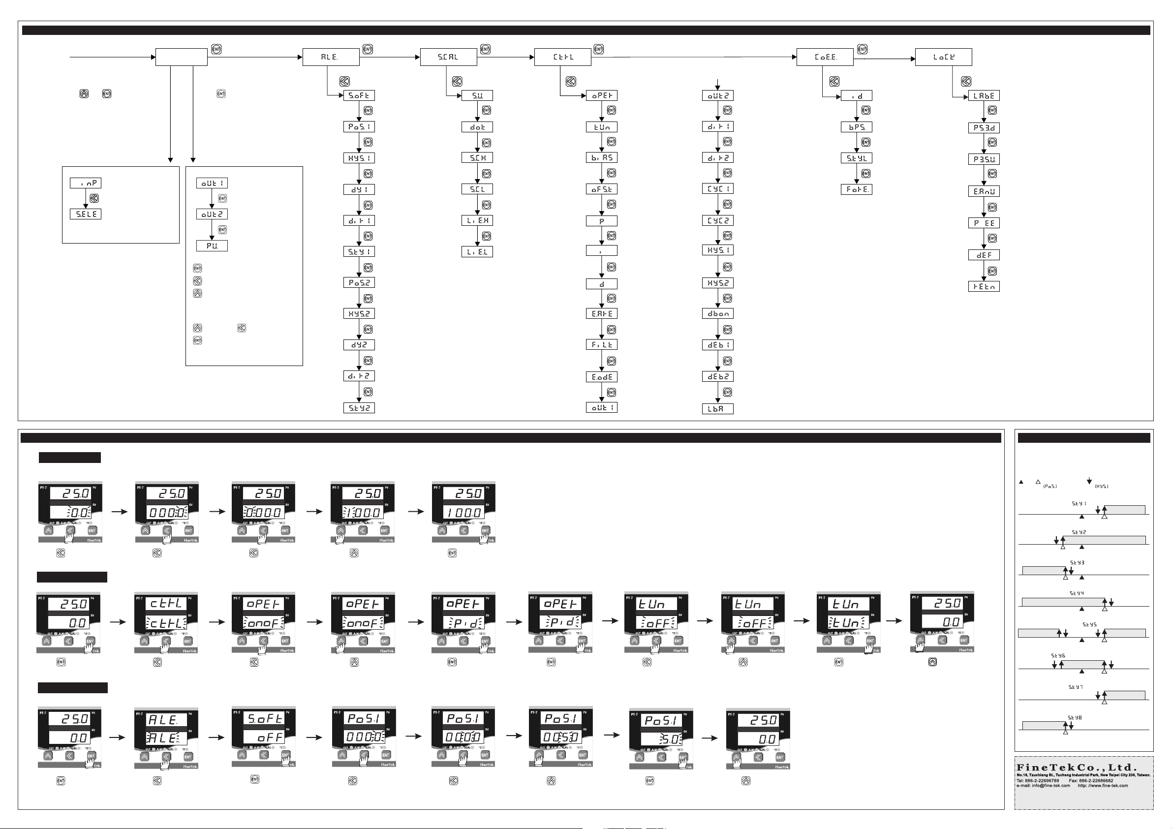
1.Quick Setup
If SV=100, the se tu p pr oc edure is as below:
Press t o ent er SV s et tin g
mode
Pre ss to Mod if d Pre ss to shi ft t o fou r dig it
posit ion
2. Auto Tuning
Press t hre e tim e
Pre ss to ent er c ont rl op ti on Pre ss to ent er s ett ing m od e Pre ss to cho os e PID m ode Pre ss t o sav e set ti ng Pre ss to s how T UN op ti on Press t o ent er se tt ing m ode Pre ss to cho os e TUN
Alarm Relay Direction 2
Alarm Relay Style 2
Pre ss to set 1 00 .0
SETTING PRECEGURE DIAGRAM
Pre ss to sav e se tti ng
Hold temperature
Over/ below room
Tempereture
Heater is controlled by out1
Cooler is controlled by out1
Deadband parameter of cooler
Loop break alarm
Press t o con fir m
Press t wic e bac k to
main sc ree n
ALARM MODE SETTING
All can w ith Hys teresi s and de- energi zed func tion fo r
ON/OF F contr ol
( )
( )
( )
( )
ON
: Hysteresis Setting Value
ONOFF
ONOFF
OFF
: Alarm Setting Value
: SV
Devia tion high a larm
Devia tion high a larm
Devia tion low al arm
ON OF F
Devia tion low al arm
ON OF F
Devia tion high /low alarm ( )
ON ONOFF
Band al arm
( )
OFF
3. Alarm Setting
Press t o sho w ALM op ti on Pr es s to en ter Al ar m opt ion Pre ss to ent er s ett ing m od e
Pre ss to sh ow ala rm
posit ion 1 op ti on
Pre ss to shi ft to two
digit p osi tio n
Press t o set 5 .0 va lu e
Press t o con fir m
* Flashin g SV i nd ic ate that
Auto Tune is executin g.
Pre ss twic e ba ck to m ain s cr een
*There are eight di fferent Alarm mode s,
please refer Alarm m od e se tt ing table.
Proce ss high ala rm
Proce ss low alar m
( )
( )
ON OF F
ONOFF
Made in taiwan
 Loading...