

Page 1

FINETAGESL
INSTALLATION MANUAL
* Make sure you read „Cautions in Use‟ before using it.
* The appearance and composition of the product may differ from the image.
Page 2

Copyright ©FINETEKCo., Ltd. 2019
• The copyright of this installation belongs to©FINETEK. This manual cannot be copied or
duplicated for personal user or purpose.
• To deliver the latest, accurate information on this manual, FINETEK may change certain
specifications, product composition and contents under FINETEK‟s decision without
notification.
• The manufacturer, importer or franchise is not responsible for accidental damage
including injury or other damages from inappropriate use or manipulation of this
product.
The year above is when this manual is written.
FINETAG is the registered trademark of FINETEK Co.,Ltd.
Ethernet™is the registered trademark of Xerox Corporation.
Microsoft™, MS-DOS™, Windows™ and Windows NT™ are registered trademark of the
U.S. Microsoft Corporation used in the U.S. and other countries.
Page 3

About This Manual.
You are welcomed as a new customer of ©FINETEK.
For proper use of the product you purchased, please understand this manual before
use. It will help you operate the product if you frequently refer to this manual.
This manual guides you to install and use the product. If any explanation is missing,
the Windows screen may be captured for explanation.
This manual is written for ordinary users and may not explain internal technical
issues.
This manual may not contain information on certain computer hardware or
operation system used in the product, application software in use, etc.
Being unable to use the whole image when explaining a computer screen, some of
the screens are explained by using text.
©FINETEK is consistently improving all products and there are changes and
improvement in technology at any time.Thus, some changes, remodeling and
improvement may not be reflected in this manual.
Page 4
When used wrong, it may be highly dangerous.
Cautions in Use
Before using the product, make sure to read „Cautions in Use‟ for proper use. „Cautions in
Use‟ deal with important materials regarding safety, so make sure you stick to them.
There is danger of fire or electric shock for the following.
Connect the product power cord only to the AC socket specified in the use
manual or product manual.
Do not spill water in the product nor expose the product to moisture. Never
touch the power plug with wet hand
Do not place heavy object (including this product itself) on the power cord. The
power cord may be damaged.
Do not place a container with liquid or small metal object on the product. The
liquid or metal object may enter the product.
Do not scratch, bend, twist, pull or heat the power cord to damage it.
Do not remove the product case on your own.
Do not remodel the product by yourself.
Use the power cord enclosed with this product. Do not use any other cords.
There is danger of electric shock. In case you need internal inspection or
maintenance, contact a franchise store.
In case of smoke, smell, noise or alien substance or liquid enters the product,
immediately turn off the power and unplug the power cord.There is danger of fire or
electric shock when the product is used in this situation, so request repair to a
franchise store.
When the product is dropped or damaged, turn off the power and unplug the power
cord. There is danger of fire or electric shock when the product is used in this
situation, so request repair to a franchise store.
Do not leave the power cable or other tables on passages. People may trip over.
Page 5
When used wrong, it may cause small damages.
Refers to requirements, limitations in manipulation. Handle the
product properly to prevent damages.
Cautions in Use
• When the product is stained, use soft cloth or towel to wipe. Never use chemical
solution (thinner, solvent, etc.) for wiping.
• Never use or leave the product in the following places
- A place too cold or hot
- A place with high moisture or dramatic temperature change
- Dusty place
• Do not place a magnetic object around this product.
• Static electricity may damage the internal parts of this product.Release static
electricity within your body before touching the terminal of the product backside or
the electric parts in the product.
• When assumed that the product is damaged beyond repair, or that its lifespan is
over, observe the local regulations for disposal of lead, battery, plastic, etc.
This product may not operate normally due to unstable power or electric shock.
Make sure to use proper power.
When connected with an external device, it may malfunction due to external factors.
Use verified external device. Also, have the product regularly inspected by installation
experts.
Page 6

Chapter
I
Product Composition
Page 7
FINETAG ESL INSTALLATION MANUAL
I.PRODUCT COMPOSITION
9
1. System Composition
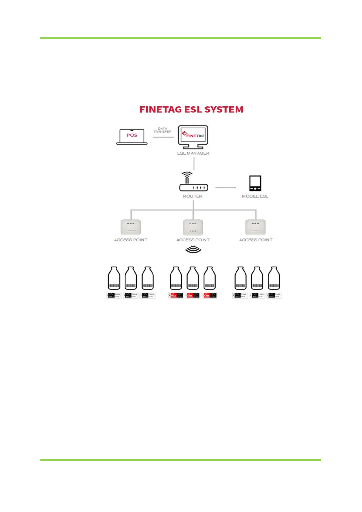
• System flow chart
-. POS: Market management server with product and price information
-. ESL Manager: A server that receives data from POS and sends data to AP and checks
operation status of AP and TAG
-. Router :Path connecting server to distributed AP
-. AP :The role of receiving and transmitting TAG and data over wireless communication
by receiving data from ESL Manager server through TCP/IP.
-. TAG: The role of displaying data by receiving it via wireless communication from AP.
Page 8
FINETAG ESL INSTALLATION MANUAL
I.PRODUCT COMPOSITION
10
Number of Tags managed per AP
Maximum4,000 units
Distance between APand Tag for communication
Maximum 20m
There may be variance depending on installation
environment, network status and other conditions.
2. System Operation Specifications
Page 9
FINETAG ESL INSTALLATION MANUAL
I.PRODUCT COMPOSITION
11
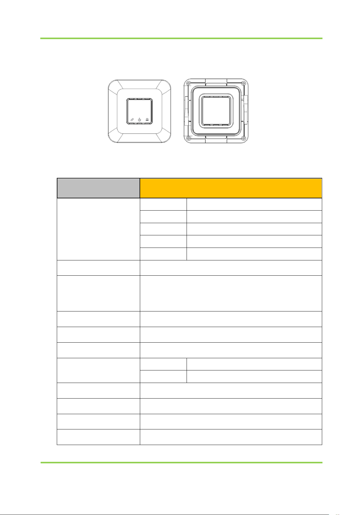
3. AP Specifications
Model
INDICATOR
LED Color
Sign
Red
Power
Green
Ethernet link
Amber
Ethernet Activate
Blue/Red
Operation Active(Blue) / Error(Red)
Network
Ethernet (10/100 Base)
Wireless
Communication
IEEE 802.15.4 Based on 2.4GHz ISM Band,
Data Rate: 250Kbps,
Service Area: Radius Max. 30m (Line of Sight)
Antenna
Approval
FCC,KC
ROHS
ROHS Compliance
Power
DC
5V / 3A
PoE
IEEE802.3af Class 1
Operating Temperature
5°C ~ 40°C / 41°F~104°F
Operating Humidity
0%~80% / non-condensing
Size
210mm x 210mm x 40mm(H)
Weight
445g
<Front Side><Rear Side>
FNTAP
External Dipole Antenna, 3.05dBi
Page 10
FINETAG ESL INSTALLATION MANUAL
I.PRODUCT COMPOSITION
12
Model
AP
Maximum Transmit Power
2.4GHz - 802.15.4 (Zigbee)
3.5 dBm (RF1), 2.5 dBm (RF2)
Available Transmit
Power Setting
2.4GHz
20.0 dBm (100mW)
18.2 dBm (66mW)
16.4 dBm (44mW)
14.2 dBm (27mW)
11.7 dBm (15mW)
09.2 dBm (9mW)
Caution: Maximum transmission power setting complies with regulations for each
channel or country.
Page 11
FINETAG ESL INSTALLATION MANUAL
I.PRODUCT COMPOSITION
13
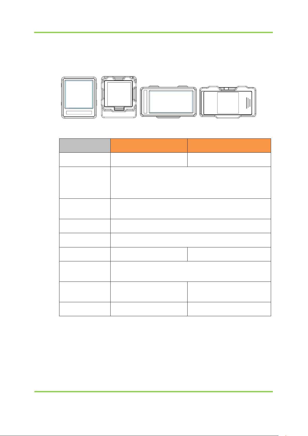
4. TAG Specifications
Model
FNT16
FNT22
Display
e-Paper 1.6" Matrix
e-Paper 2.2" Matrix
Wireless
Communication
IEEE 802.15.4 Based on 2.4GHz ISM Band,
Data Rate: 250Kbps,
Service Area : Radius Max. 30m (Line of Sight)
Maximum
Transmit Power
Approval
FCC, KC
ROHS
ROHS Compliance
Power
Coin Battery CR2450 x 1
Coin Battery CR2450 x 2
Operating
Temperature
0°C ~ 40°C / 41°F~104°F
Size
36.6mm x 43.2mm
x 12.4mm (H)
65.1mm x 34 mm
x 12.4mm (H)
Weight
12.28g
18.27g
①FNT16, FNT22
<FNT16><FNT22>
2.4GHz - 802.15.4 (Zigbee)
2 dBm
Page 12
FINETAG ESL INSTALLATION MANUAL
I.PRODUCT COMPOSITION
14
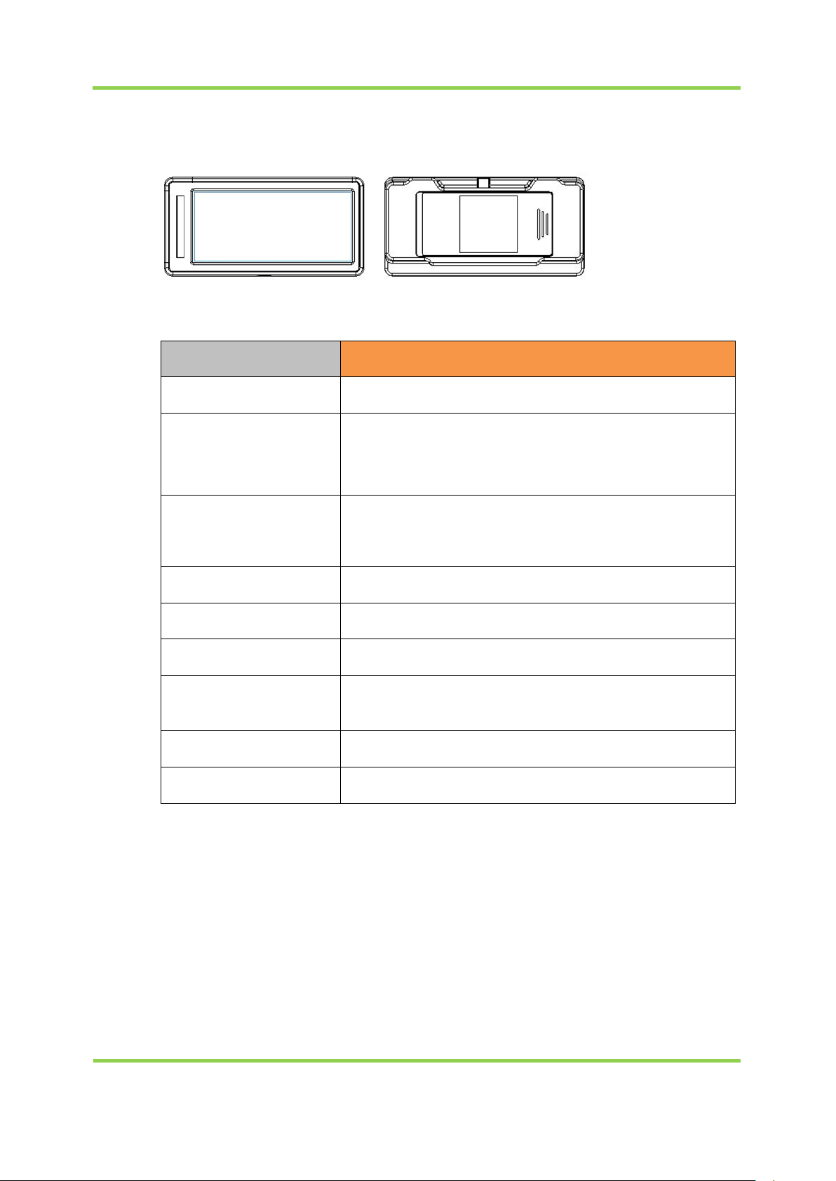
②FNT29
Model
FNT29
Display
e-Paper 2.9" Matrix
Wireless
Communication
IEEE 802.15.4 Based on 2.4GHz ISM Band,
Data Rate: 250Kbps,
Service Area : Radius Max. 30m (Line of Sight)
Maximum
Transmit Power
Approval
TBD
ROHS
ROHS Compliance
Power
Coin Battery CR2450 x 2
Operating
Temperature
0°C ~ 40°C / 41°F~104°F
Size
84.9mm x 41.5mm x 12.4mm
Weight
27.35g
<FNT29>
2.4GHz - 802.15.4 (Zigbee)
0 dBm
Page 13
FINETAG ESL INSTALLATION MANUAL
I.PRODUCT COMPOSITION
15
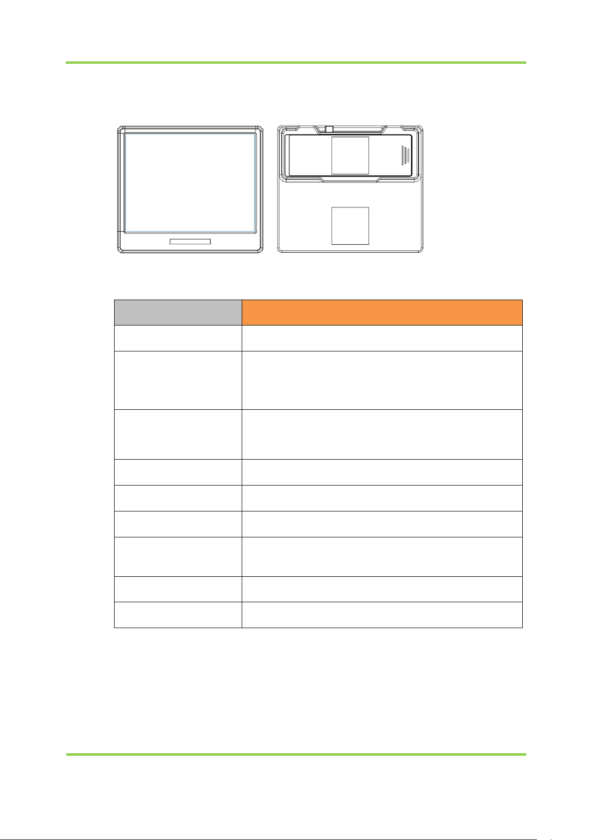
③FNT42
Model
FNT42
Display
e-Paper 4.2" Matrix
Wireless
Communication
IEEE 802.15.4 Based on 2.4GHz ISM Band,
Data Rate: 250Kbps,
Service Area : Radius Max. 30m (Line of Sight)
Maximum
Transmit Power
Approval
FCC, KC
ROHS
ROHS Compliance
Power
Coin Battery CR2450 x 3
Operating
Temperature
0°C ~ 40°C / 41°F~104°F
Size
95.8mm x 82.9mm x 13.2mm
Weight
68.88g
<FNT42>
2.4GHz - 802.15.4 (Zigbee)
2 dBm
Page 14
FINETAG ESL INSTALLATION MANUAL
I.PRODUCT COMPOSITION
16
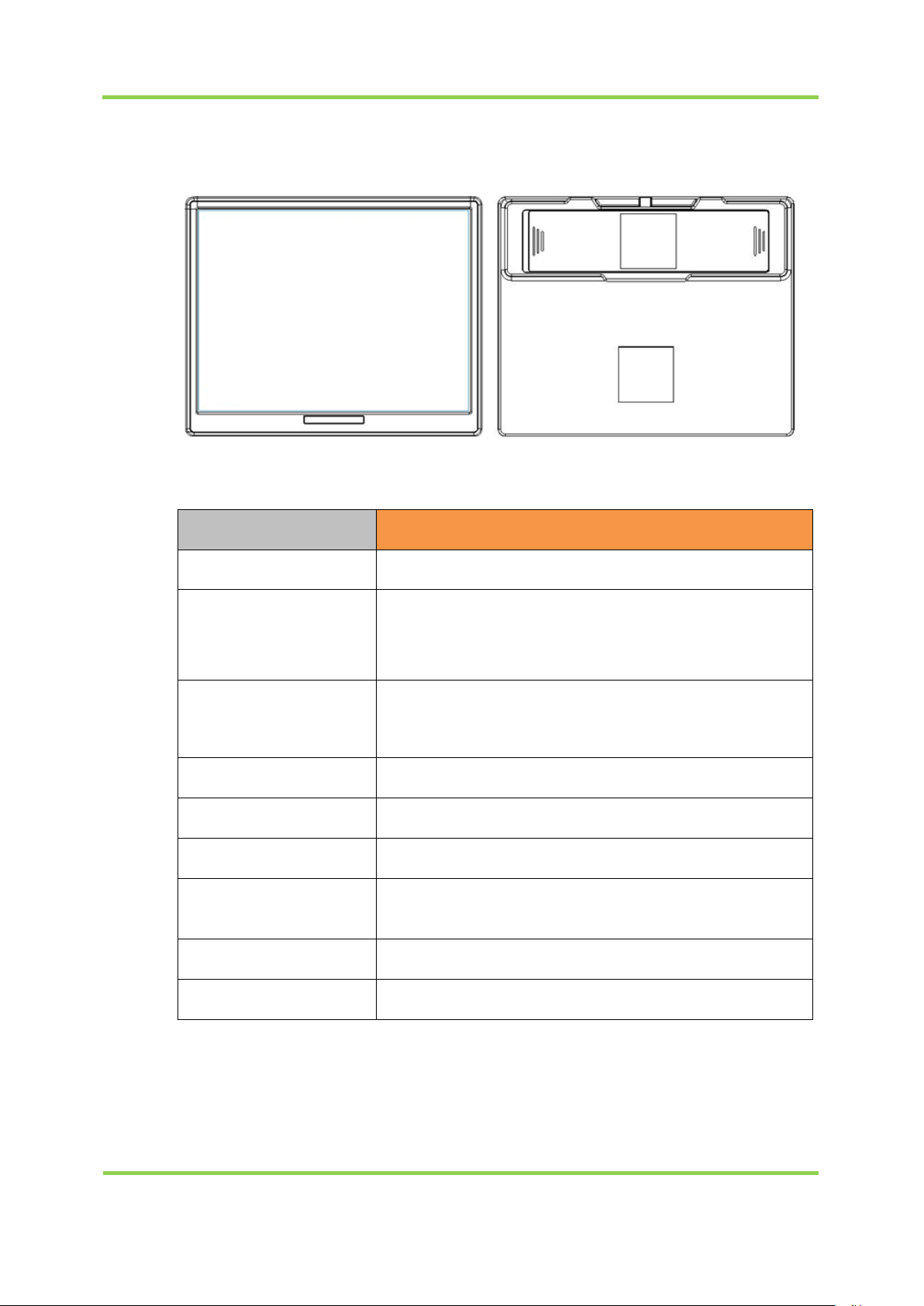
④FNT58
Model
FNT58
Display
e-Paper 5.8" Matrix
Wireless
Communication
IEEE 802.15.4 Based on 2.4GHz ISM Band,
Data Rate: 250Kbps,
Service Area : Radius Max. 30m (Line of Sight)
Maximum
Transmit Power
Approval
TBD
ROHS
ROHS Compliance
Power
Coin Battery CR2450 x 4
Operating
Temperature
0°C ~ 40°C / 41°F~104°F
Size
130.2mm x 105.4mm x 13.2mm
Weight
124.60g
<FNT58>
2.4GHz - 802.15.4 (Zigbee)
-0.5 dBm
Page 15
FINETAG ESL INSTALLATION MANUAL
I.PRODUCT COMPOSITION
17
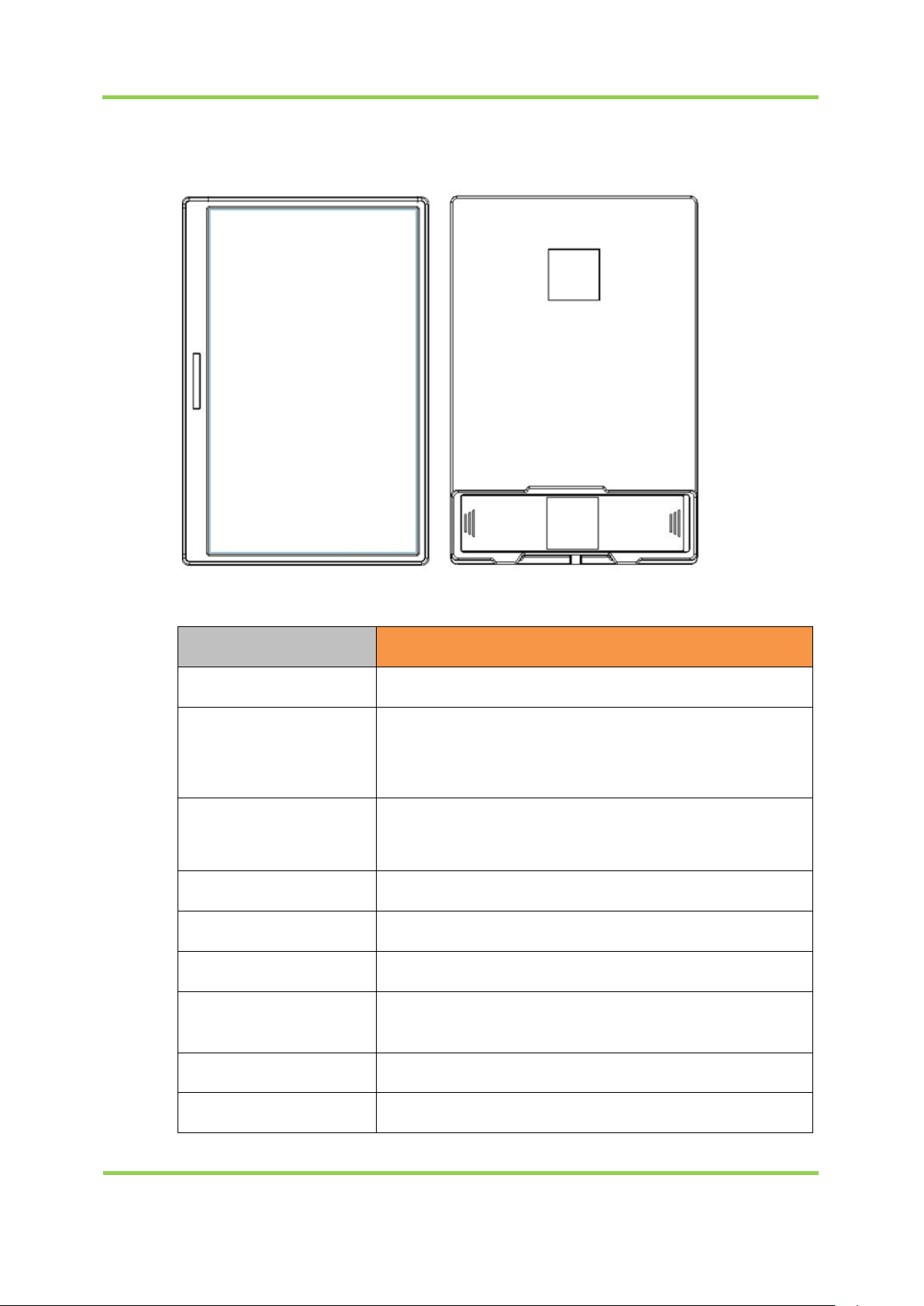
⑤FNT75
Model
FNT75
Display
e-Paper 7.5" Matrix
Wireless
Communication
IEEE 802.15.4 Based on 2.4GHz ISM Band,
Data Rate: 250Kbps,
Service Area : Radius Max. 30m (Line of Sight)
Maximum
Transmit Power
Approval
TBD
ROHS
ROHS Compliance
Power
Coin Battery CR2450 x 4
Operating
Temperature
0°C ~ 40°C / 41°F~104°F
Size
117.1mm x 175mm x 13.2mm
Weight
184g
<FNT75>
2.4GHz - 802.15.4 (Zigbee)
2 dBm
Page 16
FINETAG ESL INSTALLATION MANUAL
I.PRODUCT COMPOSITION
18
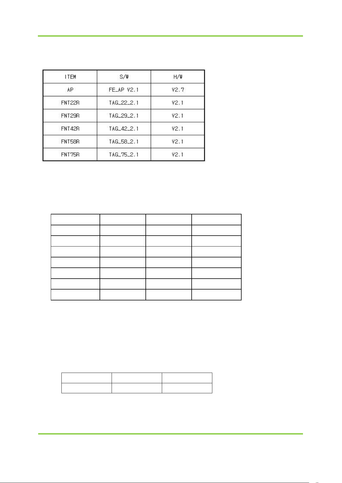
⑥Specifications
Item
TAG
AP
MAX Gain
5.3
3.05
Hardware / Software Version:
Operating Temperature:5°C ~ 40°C / 41°F~104°F
Distance :Radius Max. 30m (Line of Sight)
Transmission :2.4GHz - 802.15.4 (Zigbee)
Output Power :
MODEL Target Tolerance Max
( Unit : dBm )
FNT22R 0
FNT29R -2
FNT42R 0
FNT58R -2.5
FNT75R 0
AP RF1
AP RF2 0.50
1.50
±2
±2
±2
±2
±2
±2
±2
2
0
2
-0.5
2
3.50
2.50
Operating Frequency :2 405㎒ ~2 480㎒ (2 405㎒,2 440㎒,2 480㎒)
Antenna Type and Location : TAG(IFA Antena) / AP(Dipole Antenna)
Antenna Gain Max gain (dBi)
Page 17
FINETAG ESL INSTALLATION MANUAL
I.PRODUCT COMPOSITION
19
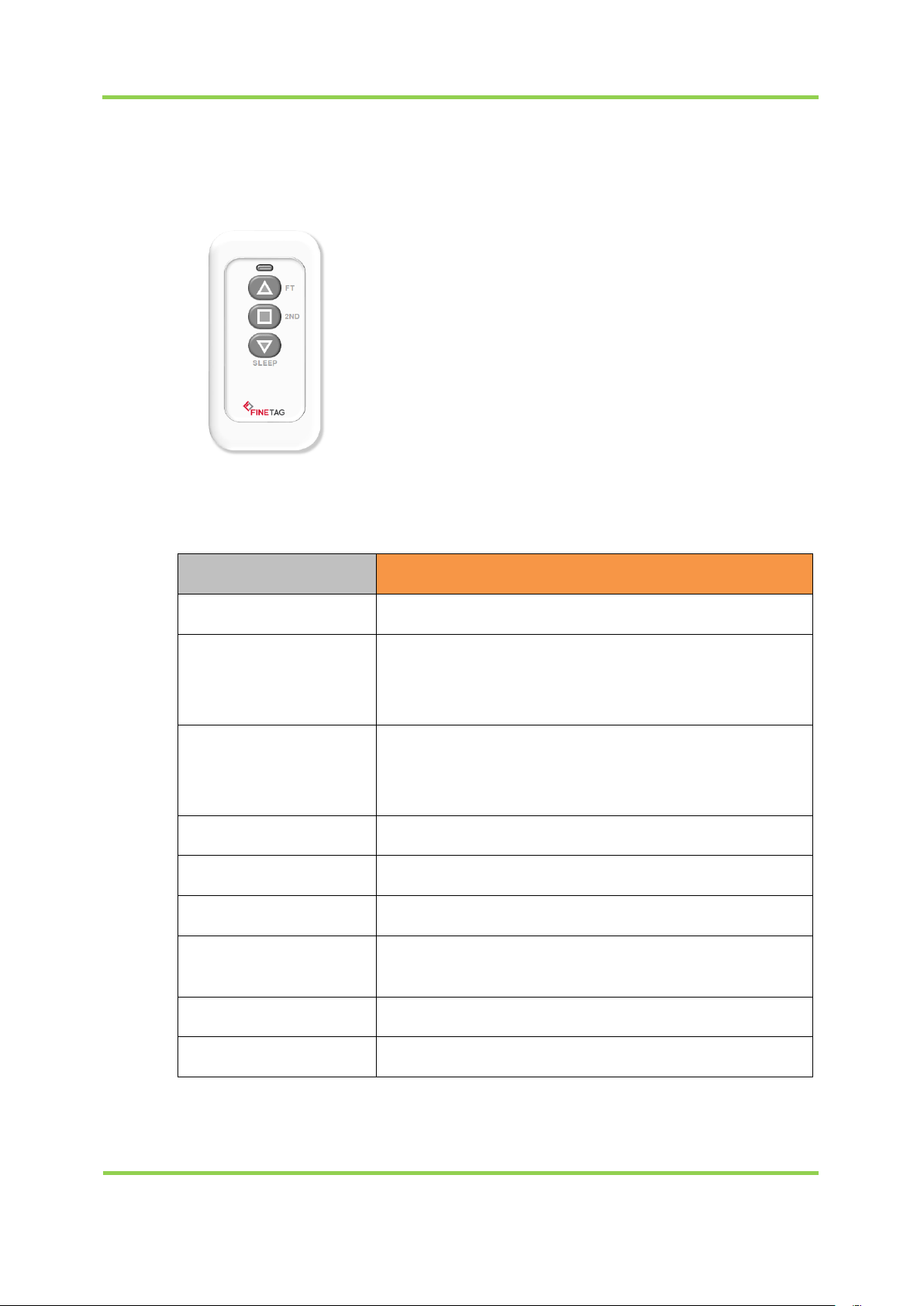
Model
IDRM1A
Display
LED Display (Red : Click / Blue : Link)
Wireless
Communication
IEEE 802.15.4 Based on 2.4GHz ISM Band,
Data Rate: 250Kbps,
Service Area : Radius Max. 30m (Line of Sight)
Maximum
Transmit Power
2.4GHz - 802.15.4 (Zigbee)
10 dBm (10mW)
Approval
FCC, KC
ROHS
ROHS Compliance
Power
Battery 12V 23A
Operating
Temperature
0°C ~ 40°C / 41°F~104°F
Size 92mm x 40mm x 15mm
Weight
40g
5. Remote Control Specifications
<IDRM1A>
Page 18
FINETAG ESL INSTALLATION MANUAL
I.PRODUCT COMPOSITION
20
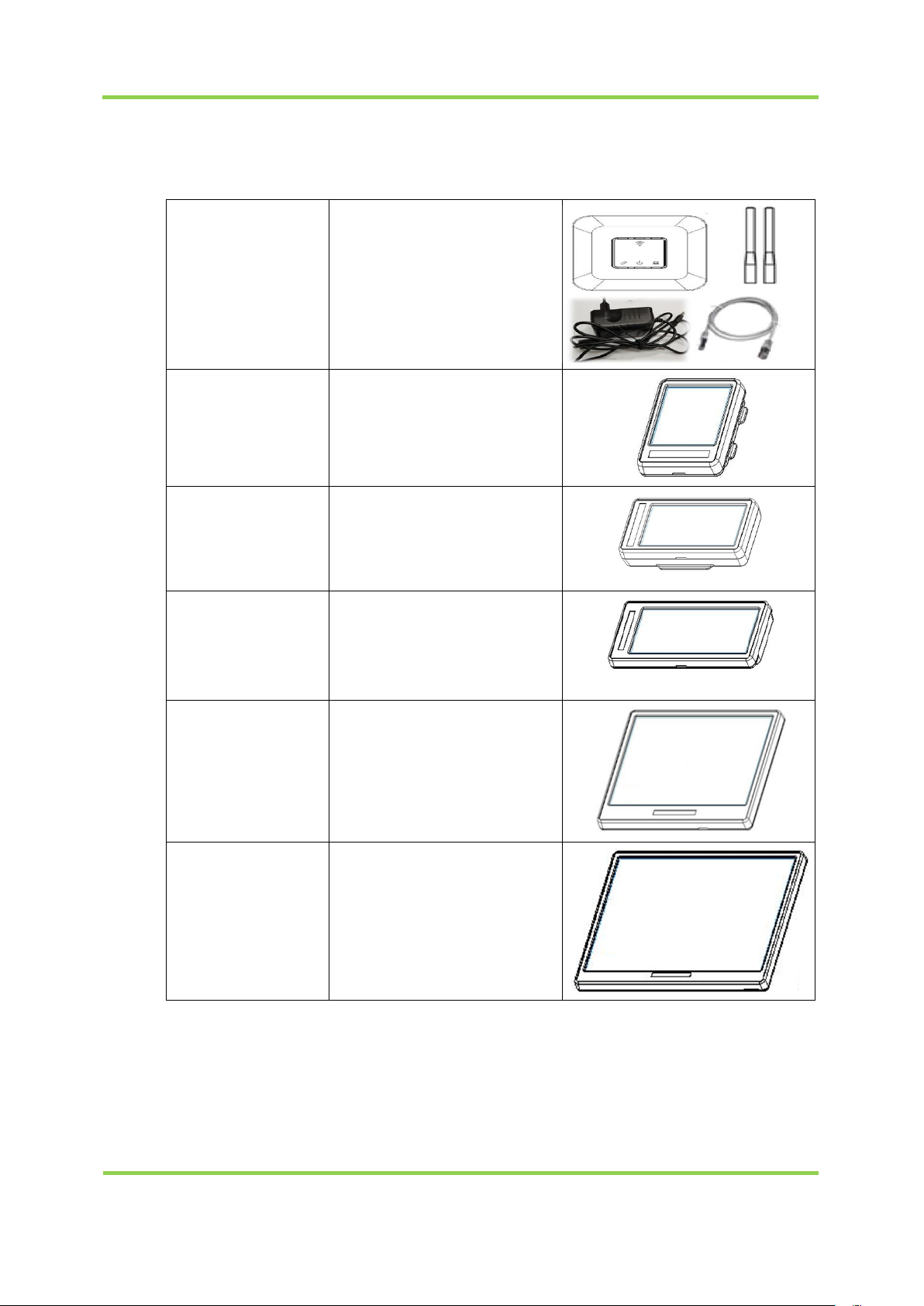
Product Display
Access Point
(AP)
AP
Power adaptor (DC
5V/3A)
RJ-45 ethernet cable
Exterior antenna
Product
Display(TAG –
FNT16)
TAG 1.6inch
Product
Display(TAG –
FNT22)
TAG 2.2 inch
Product
Display(TAG –
FNT29)
TAG 2.9inch
Product
Display(TAG –
FNT42)
TAG 4.2inch
Remote Control
(TAG – FNT58)
TAG 5.8inch
6. Product Kit Composition
Page 19
FINETAG ESL INSTALLATION MANUAL
I.PRODUCT COMPOSITION
21
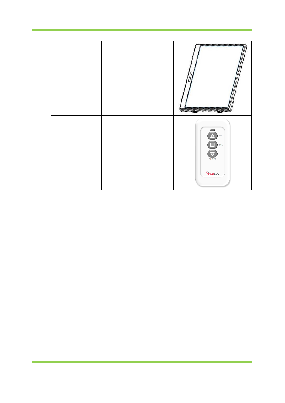
Product
Display(TAG –
FNT75)
TAG 7.5inch
Product Display
Remote Control
Remote control (IDRM1A)
Page 20

Chapter
II
Installation
Page 21
Item
Requirement
Minimum
Recommended
OS
Windows 7 SP164 or above
64bit
Windows 10
64bit
Memory
4GB or higher
8GB or higher
Disk
HDD 10GB or higher
SSD 20GB or higher
Processor
Intel Celeron 2.4 GHz
or higher
Intel i7 or higher
Ethernet
100M/1Gbps or higher
100M/1Gbps or higher
1. Software Installation
1.1 Recommended Specifications for Installation Computer
Installation of FINETAG ESL requires the following computer specifications:
1.2 Installed Software
FINETAG ESLsystem requires following software installed
Nginx (Web Server)
MariaDB(Database Server)
ESL Server
1.3 Preparations before Installation
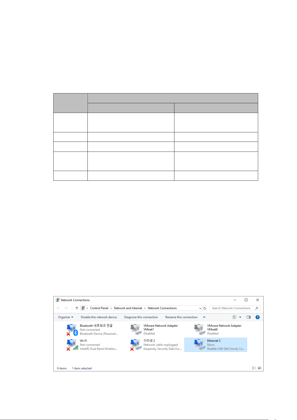
LAN should be connected to the computer to be installed and activated.
Page 22
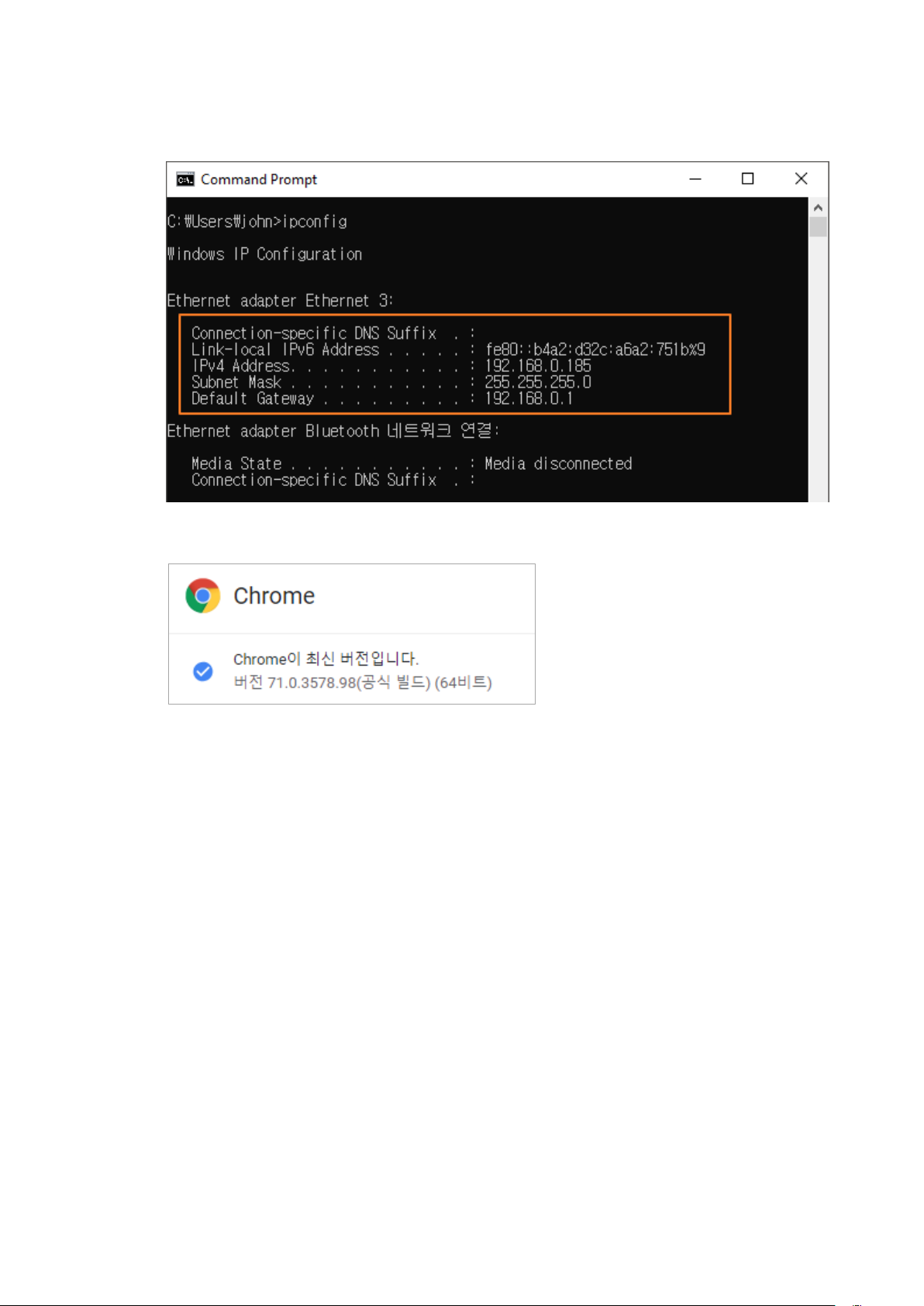
IP must be granted to the computer to be installed.
The latest version of Google Chrome browser must be installed on the computer.
(Chrome, the latest version : v71.0.3578.98 (64bit)
Page 23
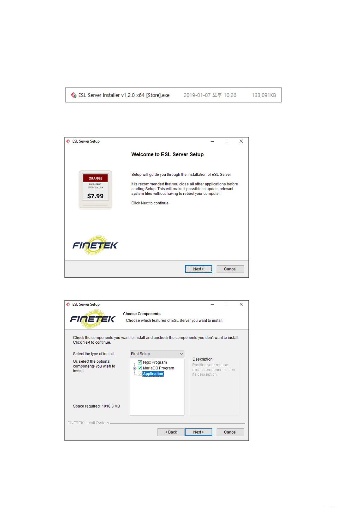
1.4 Software Installation
1. Check the installation file name.
*The file name differs depending on the software version provided.
2. Launch the installation file and click on [Next].
3. Check the installation items and click on [Next].
Page 24
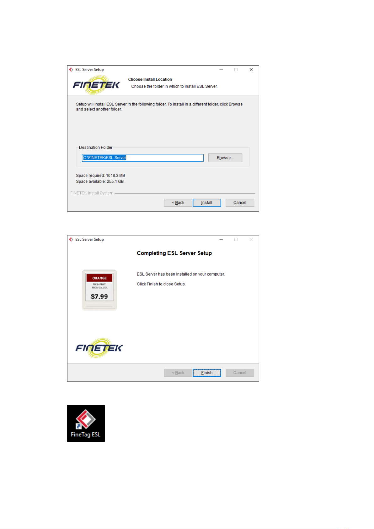
4. Check the destination folder and click on [Install].
5. Confirm installation completion and click on [Finish].
6. Find the icon below on the desktop.
Page 25

1.5 Check Software Status.
FINETAG ESL is automatically executed upon installation.Use Windows Services
Manager to check if the software operates well.
1.5.1 How to Execute Windows Services Manager
1. PressWindows+R to execute Run.
2. Enter “services.msc” and click on [OK].
1.5.2 ESL Server Check
Check on Windows Services Manager to confirm“ESL Server”isRunning.
Page 26
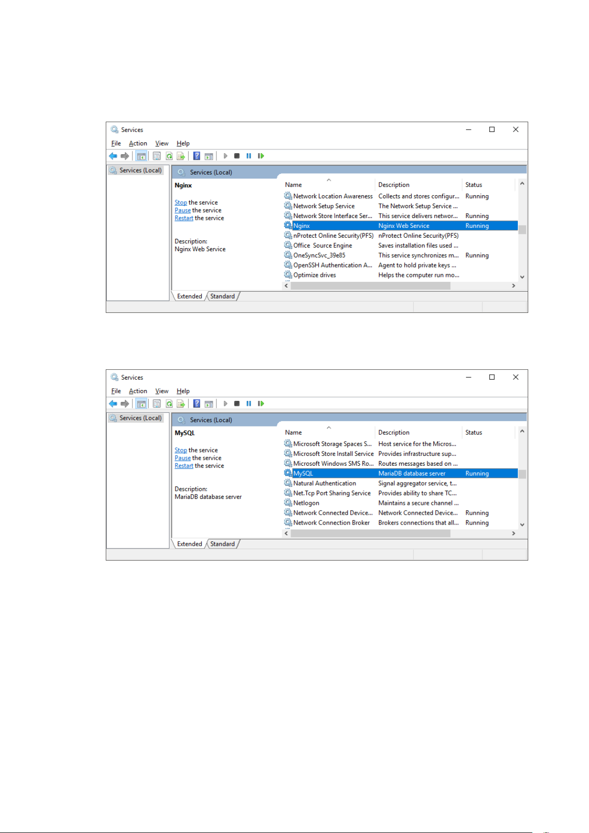
1.5.3 Check Nginx Web Server
Check that “Ngnix” is Running on Windows Services Manager.
1.5.4 Check MariaDBDatabase Server
Check that “MySQL” is Running on Windows Services Manager.
Page 27
1.6 Computer Setting
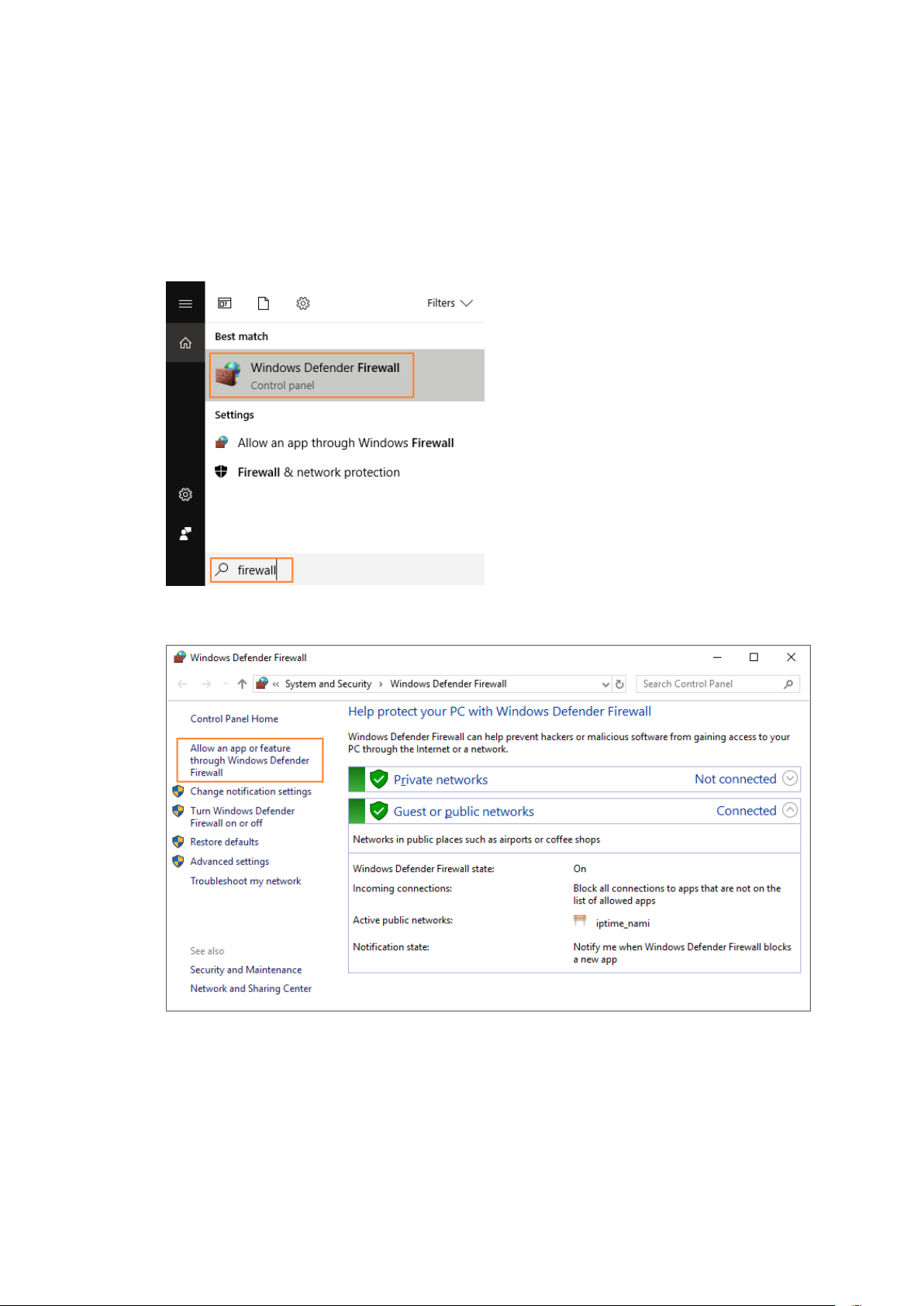
1.6.1 Add on Windows Defender Firewall List
1. Type “firewall” in Windows start menu search bar.
2. Select [Windows Defender Firewall].
3. Click on “Allow an app or feature through Windows Defender Firewall”.
Page 28
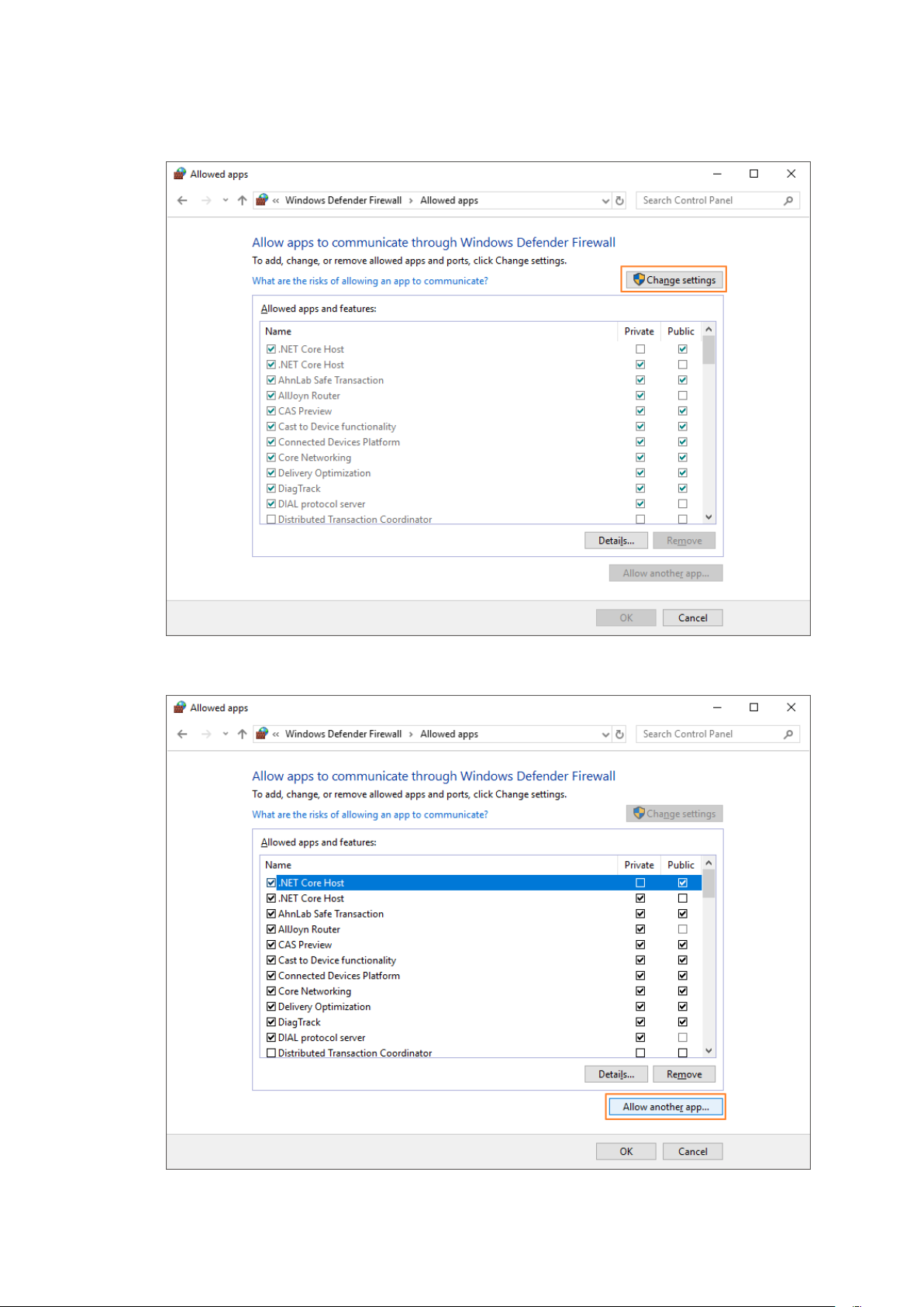
4. Click on [Change settings] to activateappslist.
5. Click on [Allow another app].
Page 29
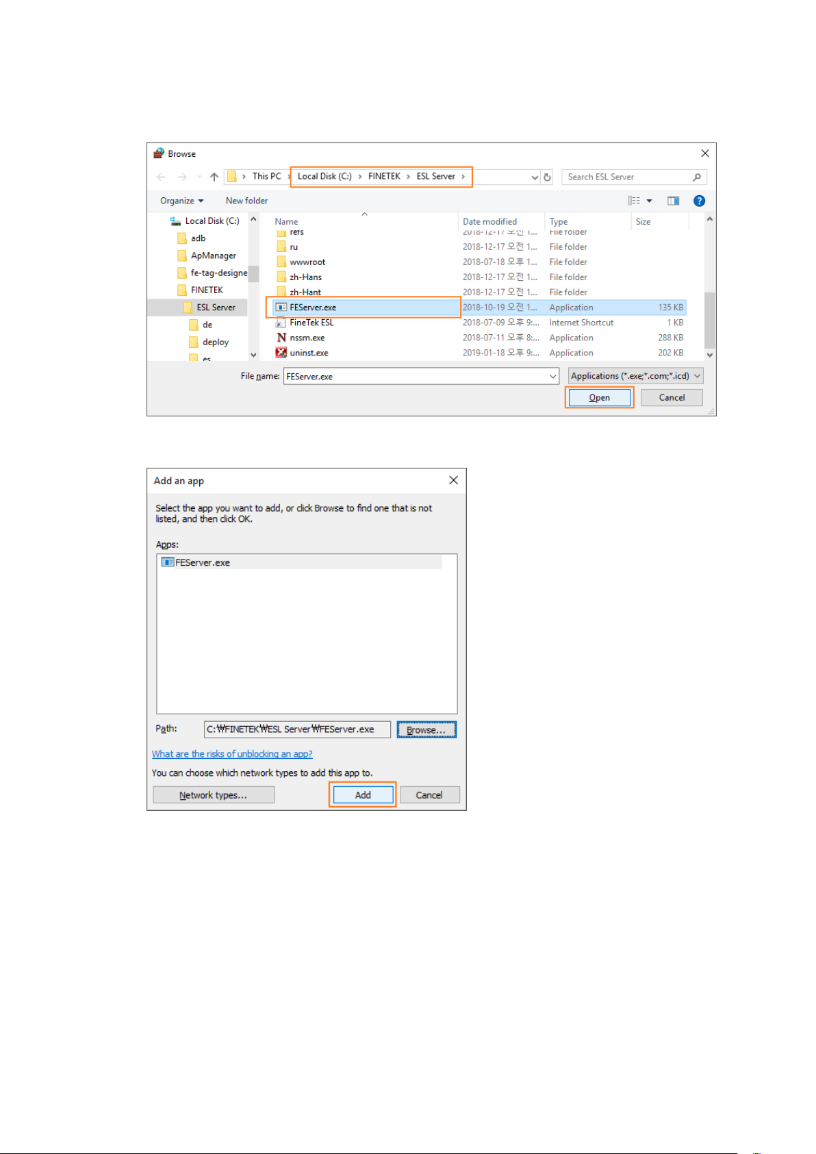
6. Select C:\FINETEK\ESL Server\FEServer.exefile and click on [Open].
7. Click on [Add].
Page 30
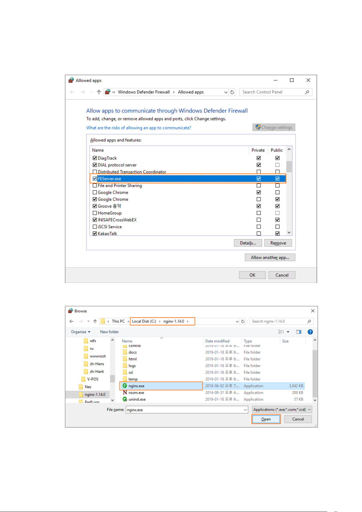
8. Check that FEServer.exe file is added on the allowed apps and features list.
Check both private and public.
9. Follow the same steps to add C:\nginx-1.14.0\nginx.exefile on the Firewall list.
Page 31
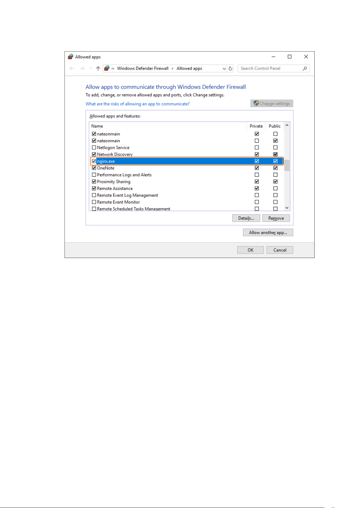
10. Click on [OK] to close the window.
Page 32
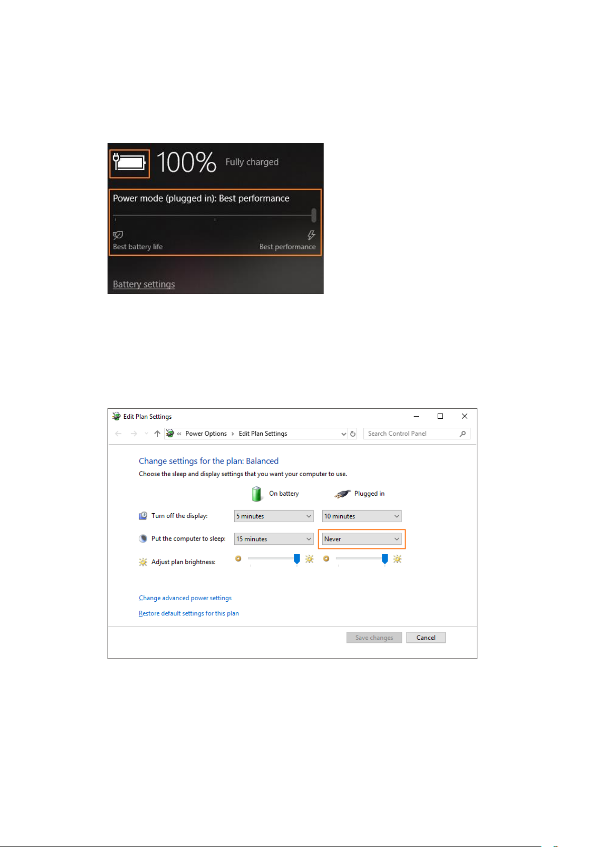
1.6.2 Power Mode Best Performance
If the software is installed on a laptop, it is recommended to connect AC power
and use “Best Performance” mode.
Caution)The way to change to “Best Performance” mode may differ from a
Windows OS version to another.
1.6.3 Dismiss Battery Save Mode
If the software is installed on a laptopturn off battery save mode.
Caution)The way to “dismiss battery save mode” may differ from a Windows OS
version to another.
Page 33
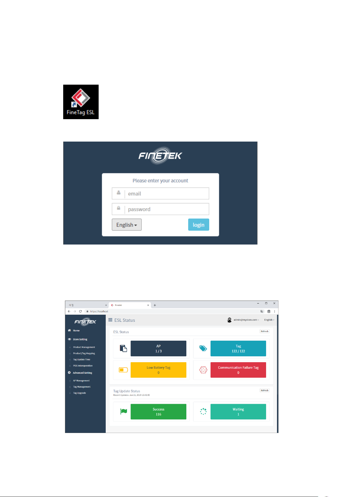
1.7 ESL Client Login
1. Double click theFINETAGESL icon on Desktop.
2. Enter email address and password on the log-in page and click on [login].
The default email address and password are presented below.
email : [email protected]
password : admin_pass
3. Check the monitoring page is presented as below.
Page 34
1.8 Delete Software
If you decide to not use ESL Software any more, you may useProgram Uninstaller to
uninstall the software.
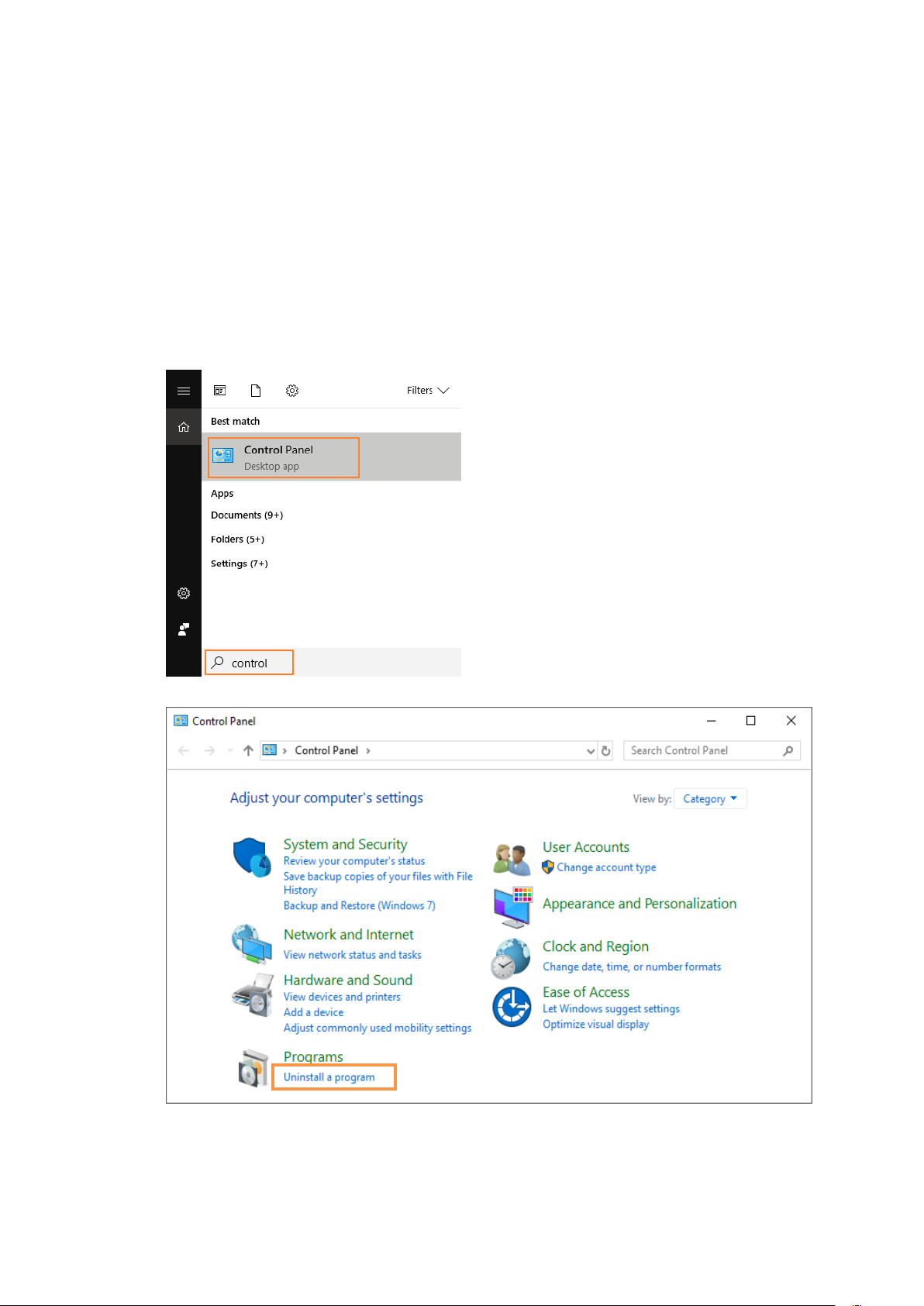
1.8.1 How to Launch Program Uninstaller
1. Type “control” in Windows start menu search bar.
2. Select [Control Panel].
3. Select [Uninstall a program]menu to openProgram and Features.
Page 35
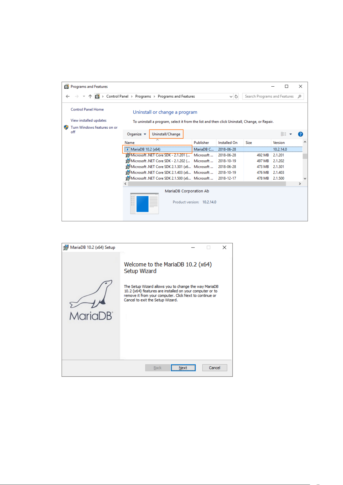
1.8.2 Uninstall MariaDBDatabase Server
1. Select “MariaDB 10.2 (x64)” and click on[Uninstall/Change].
2. Click on [Next].
Page 36
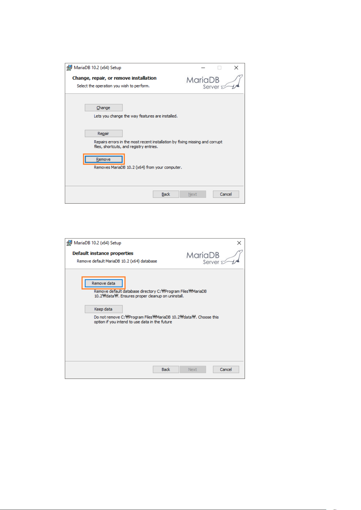
3. Select [Remove].
4. Select [Remove data].
MariaDB may not be re-installed if you select “Keep data”.
Page 37
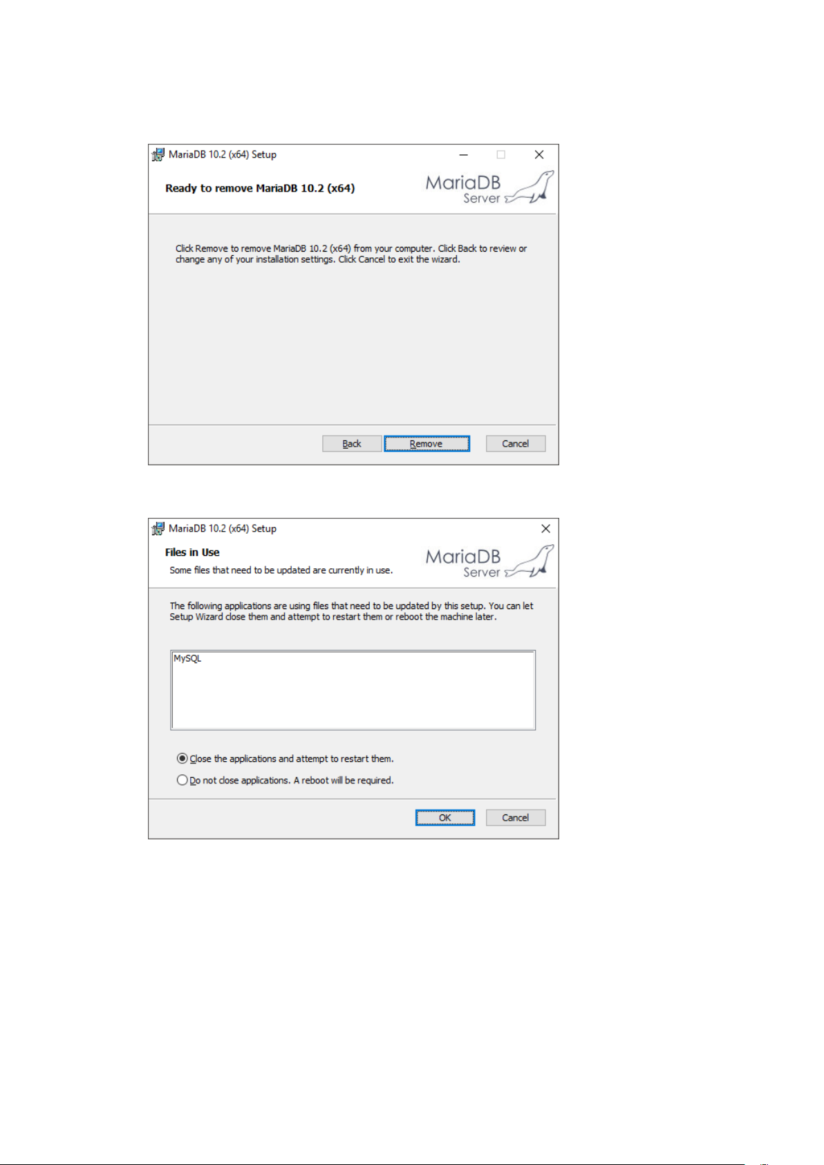
5. Click on [Remove] to start uninstallation.
6. Select “Close the applications and attempt to restart them” and click on[OK].
Page 38
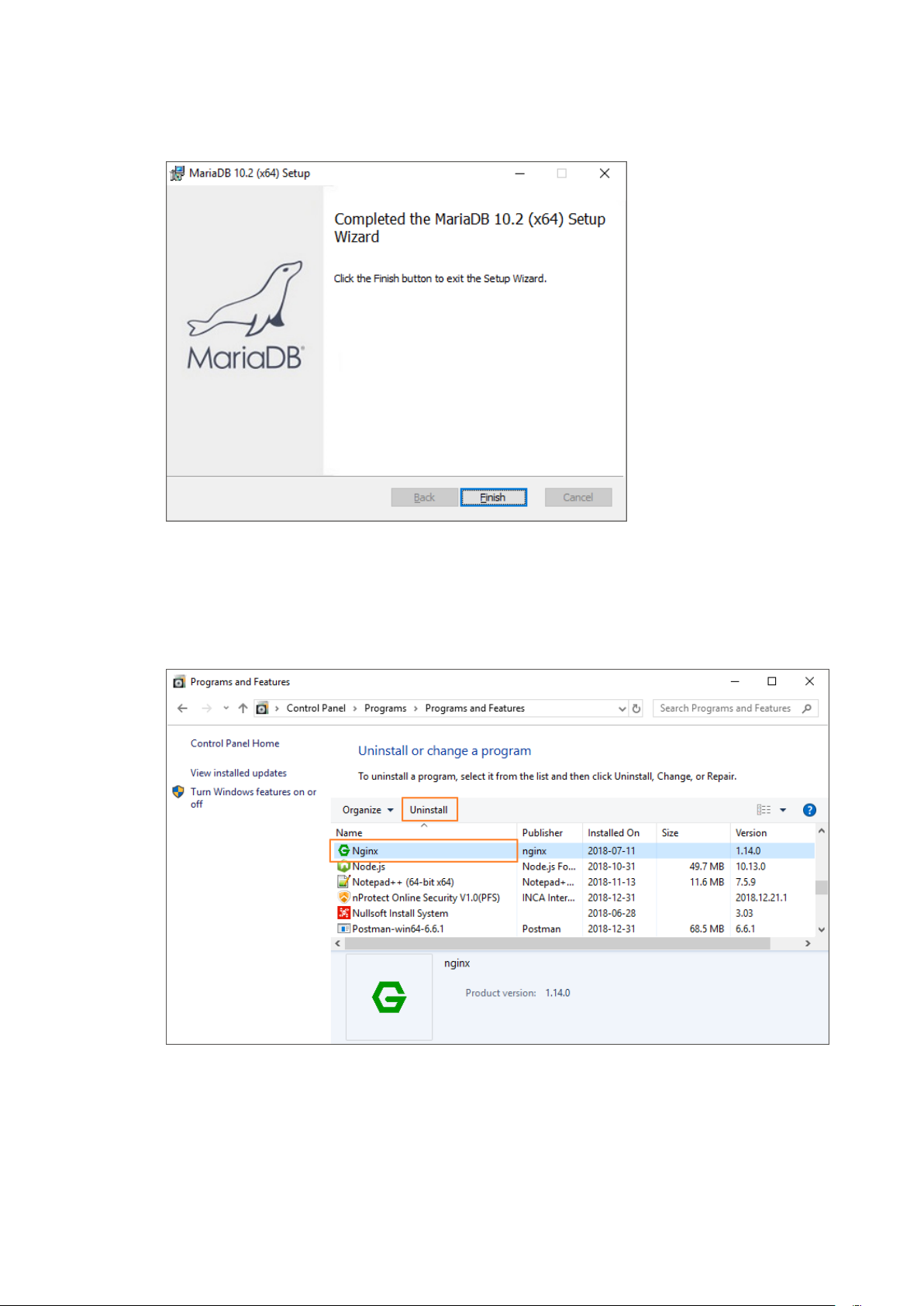
7. Click on [Finish] once uninstallation is completed.
1.8.3 Uninstall NginxWeb Server
1. Select “Nginx” and click on [Uninstall].
Page 39
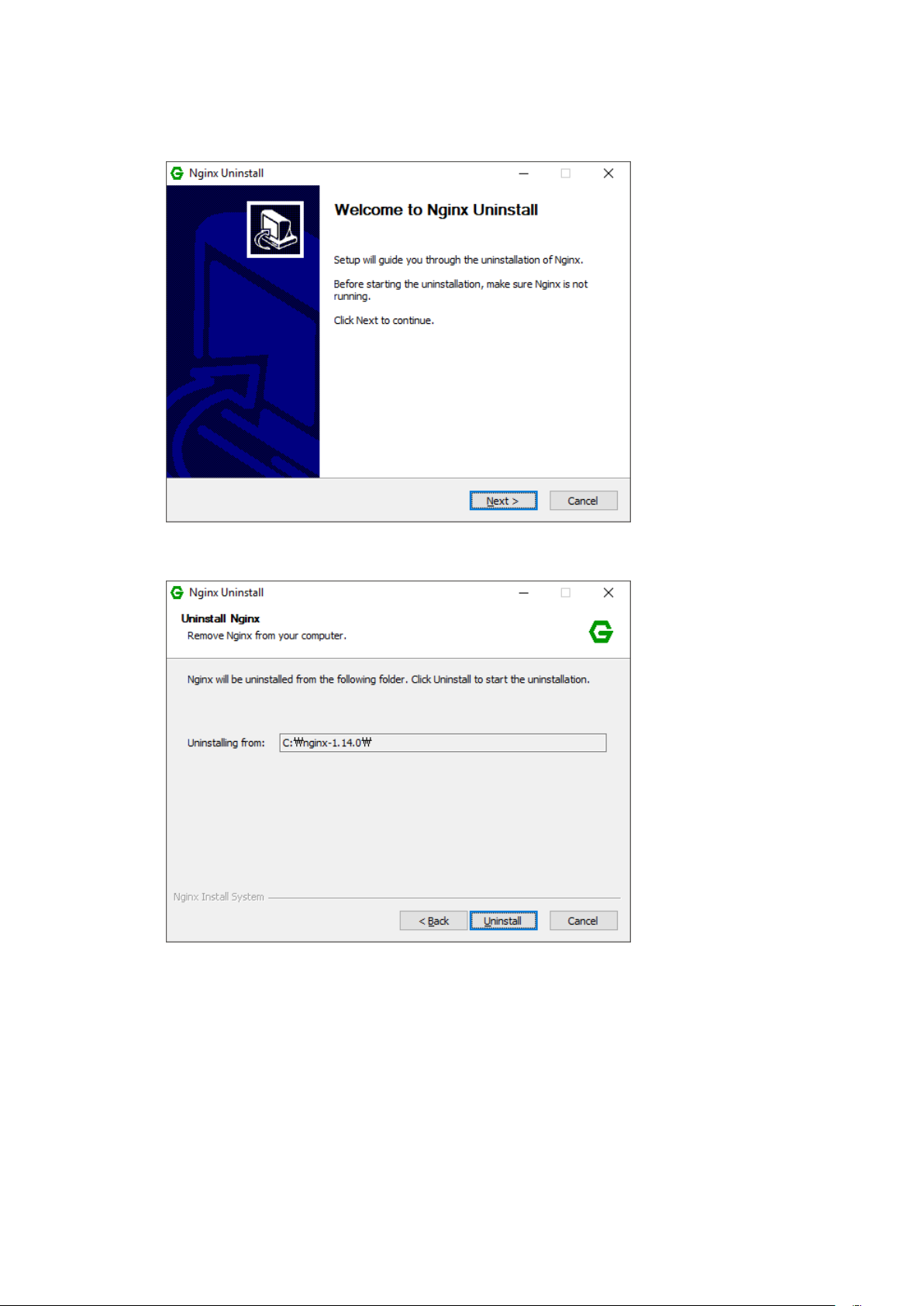
2. Click on [Next].
3. Check the uninstallation path and click on [Uninstall].
Page 40
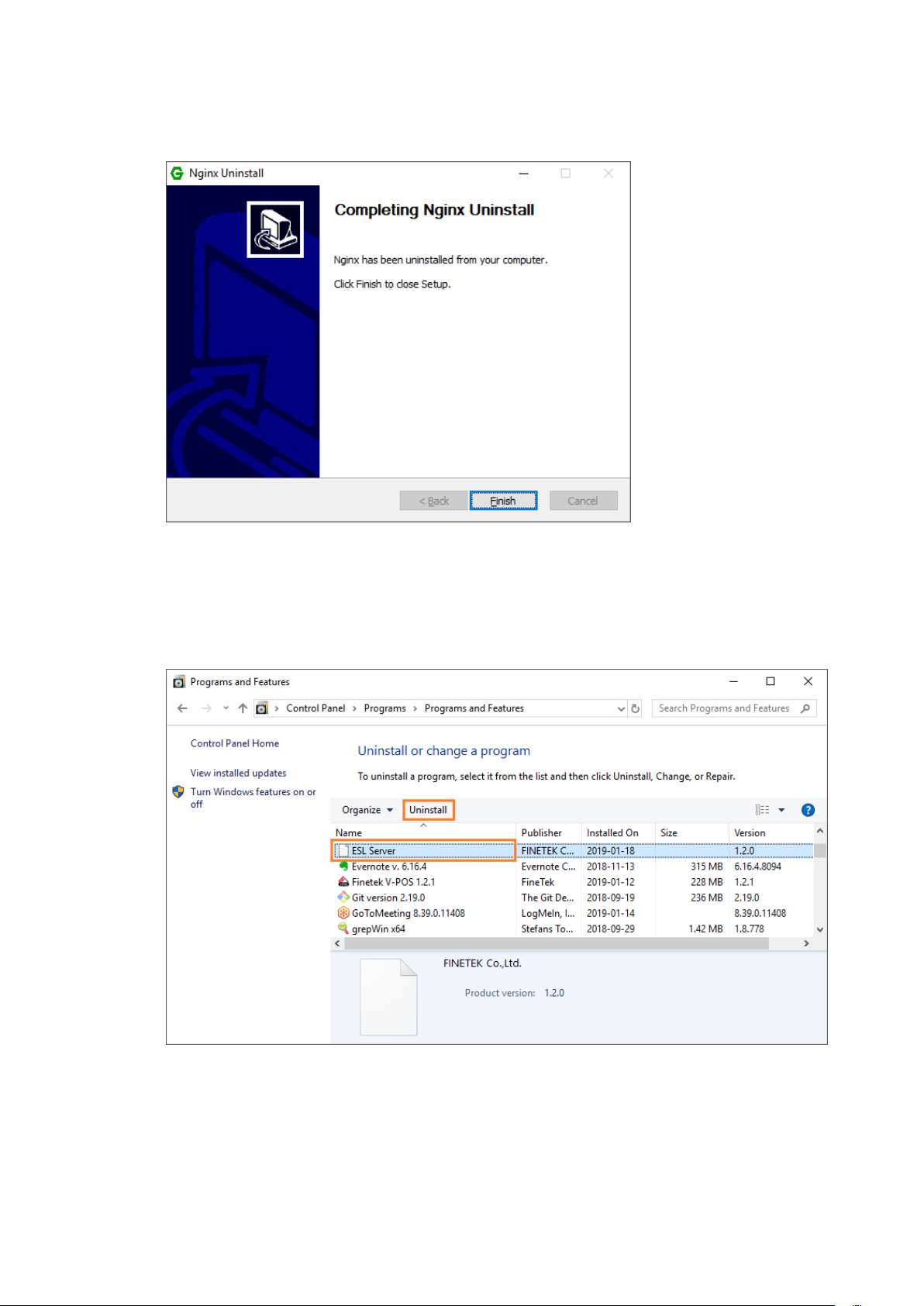
4. Click on [Finish] after uninstallation is completed.
1.8.4 ESL Server Uninstall
1. Select “ESL Server” and click on[Uninstall].
Page 41
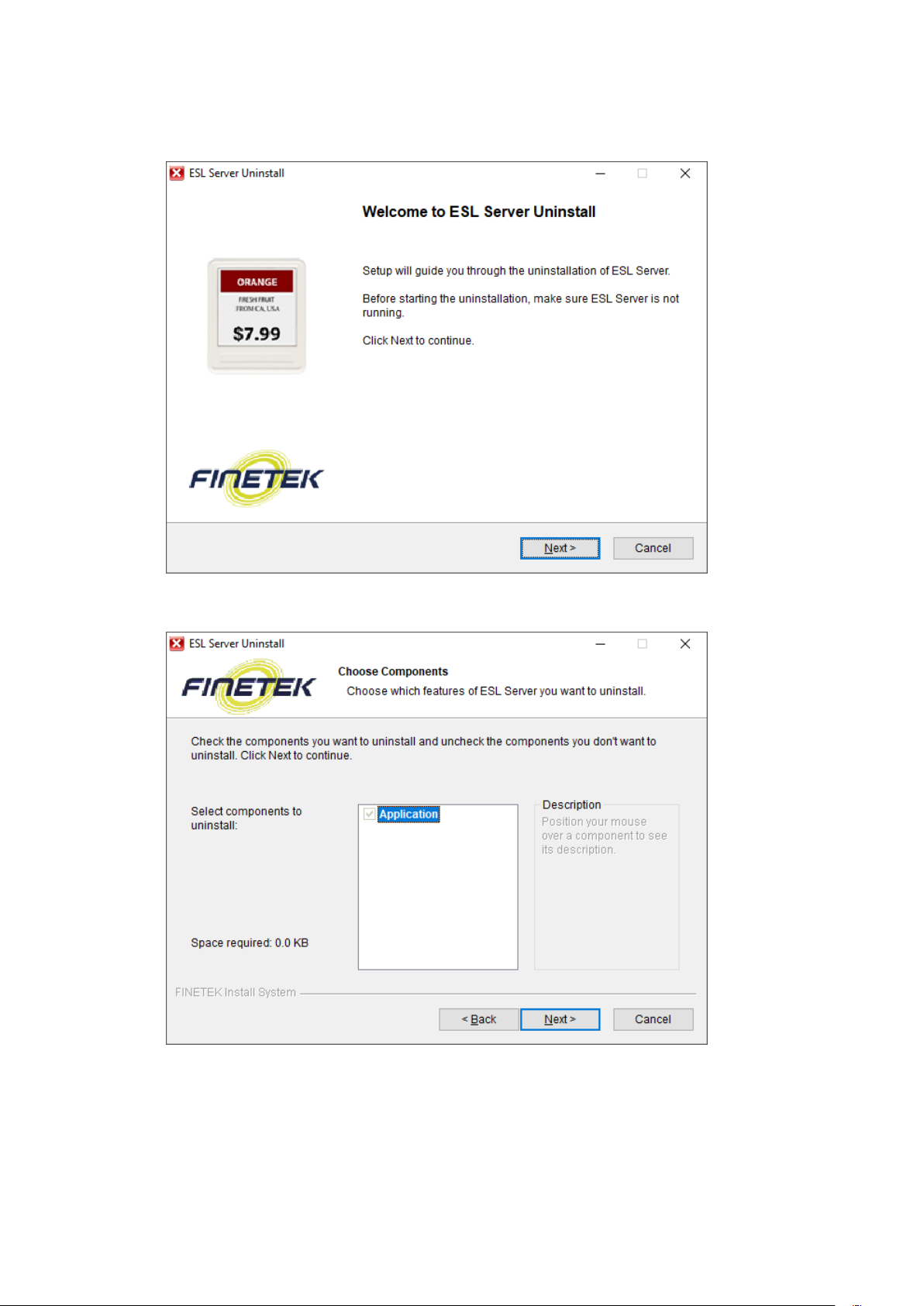
2. Click on [Next].
3. Check items to be deleted and click on [Next].
Page 42
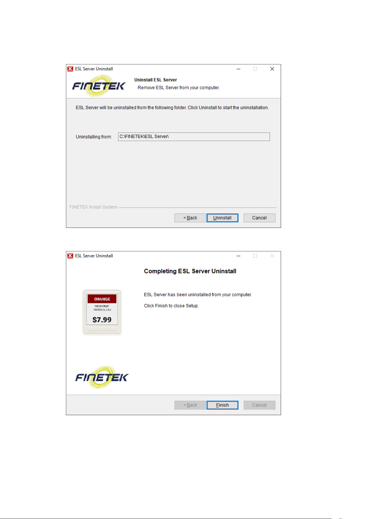
4. Check the uninstallation path and click on [Uninstall].
5. Click on [Finish] after uninstallation is completed.
Page 43
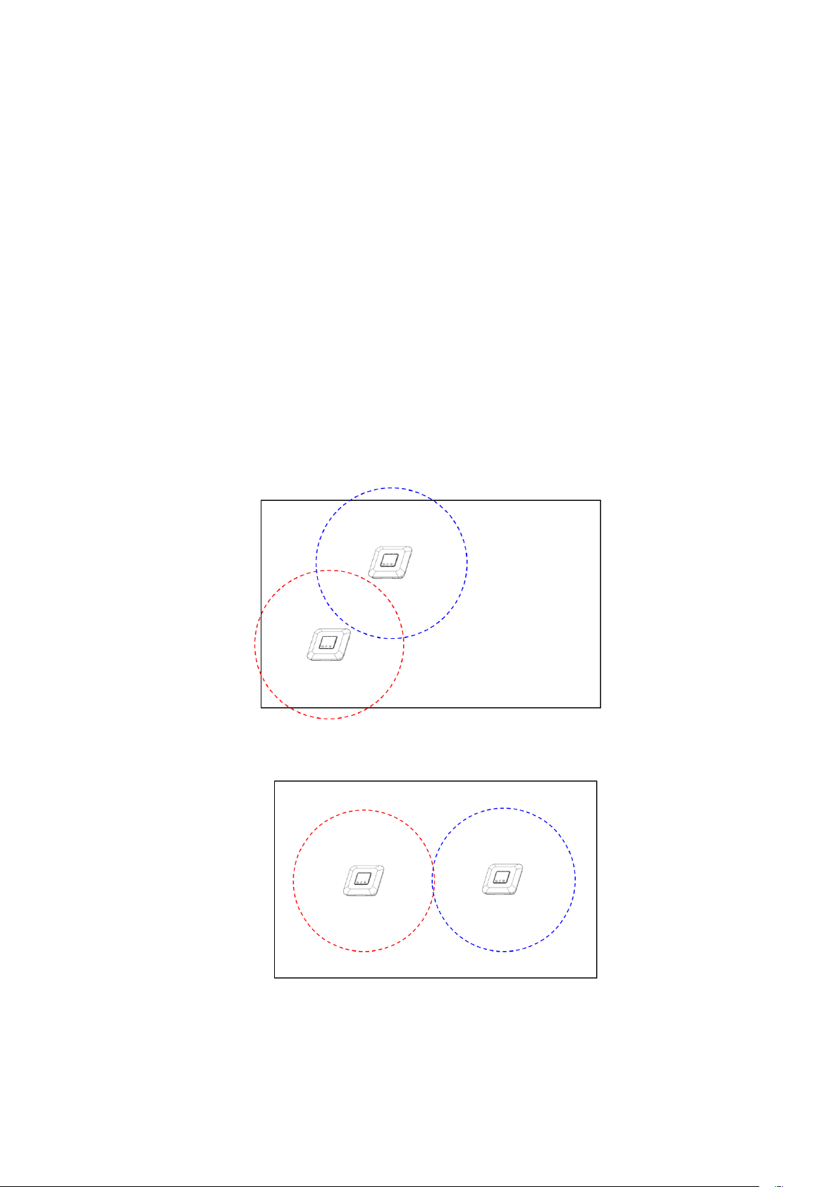
2. AP Installation and Registration
2.1 Select AP Location
To maintain AP performance at its best, consider the following select the location.
Do not install nearby industrial equipment including transformer, microwave,
refrigerator, etc.(keep apart more than 5m)
Metal, concrete, wall, etc. blocks communication so signals may be lost.
The ideal installation height is 3m(10ft.) from the ground.
Have the antenna face the ceiling to improve reception.
Place AP as close to Tag as possible.
When aligning two or more AP‟s, give enough space between the space and
the AP to raise efficiency.
<Inappropriate AP Location>
<Appropriate AP Location>
Page 44
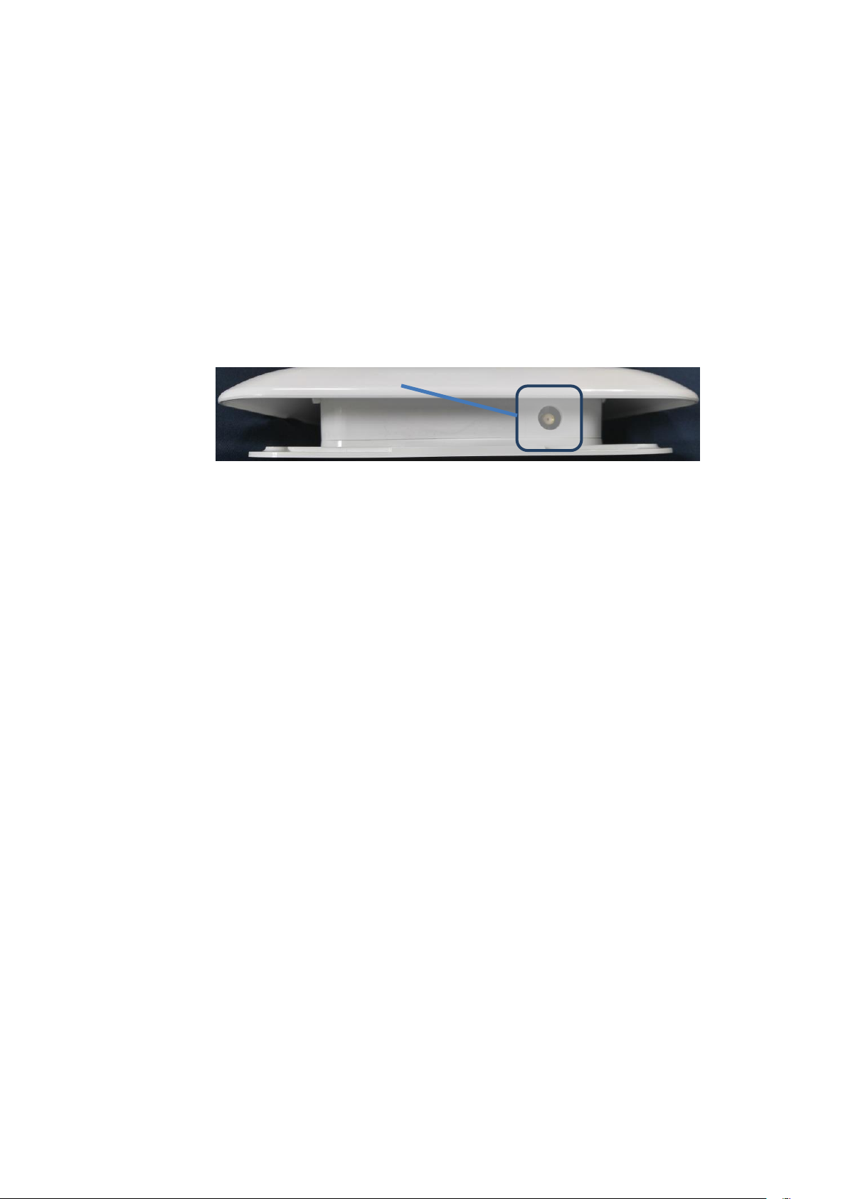
Antenna Port
2.2 APInstallation
① Ceiling Installation
When installing at ceiling, place in open place rather than in closed space,
and keep 3m or more away from the ground if possible.Also, organize the
cables to not interrupt passengers
Check if the antenna is installed at AP.
Place AP in the space Tagis installed so everyone can see it well.
Connect the cable if installation is completed.
② Wall Installation
For wall installation, fix the Wall Bracket on a wall and assemble it with the
hole on the bottom of the AP.
To install AP on a wall,
Make sure an antenna is installed.
Fix the Wall Bracket on a wall and attach the AP to the Bracketto fix it.
Page 45
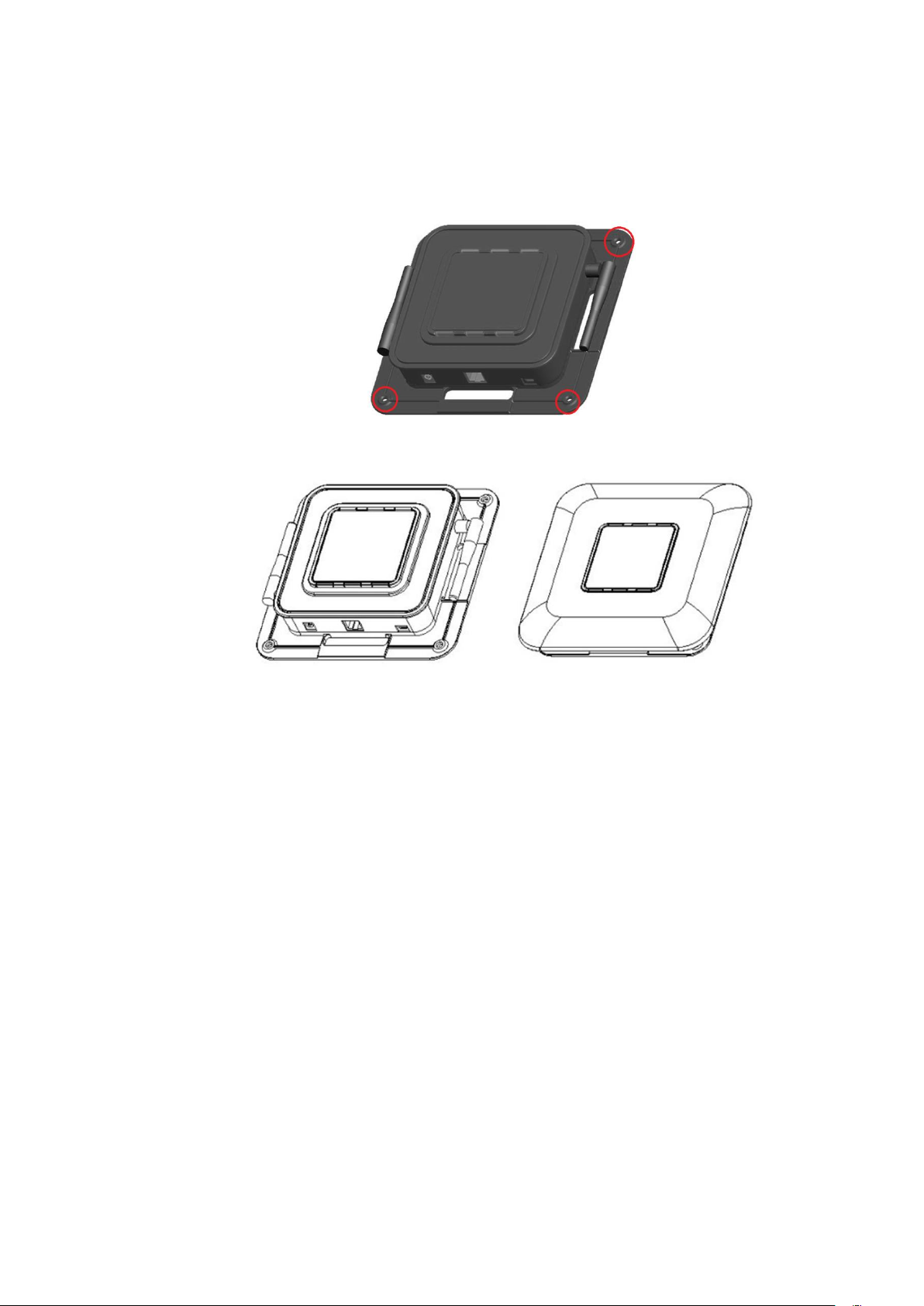
In case you do not use the Wall Bracket, get rid of the TOP case of theAP
and use the hole on the bottom to fix on a wall.
<Hole for Fixing AP>
<TOP Case Removal>
Fix the AP and place the TOP case.
Page 46
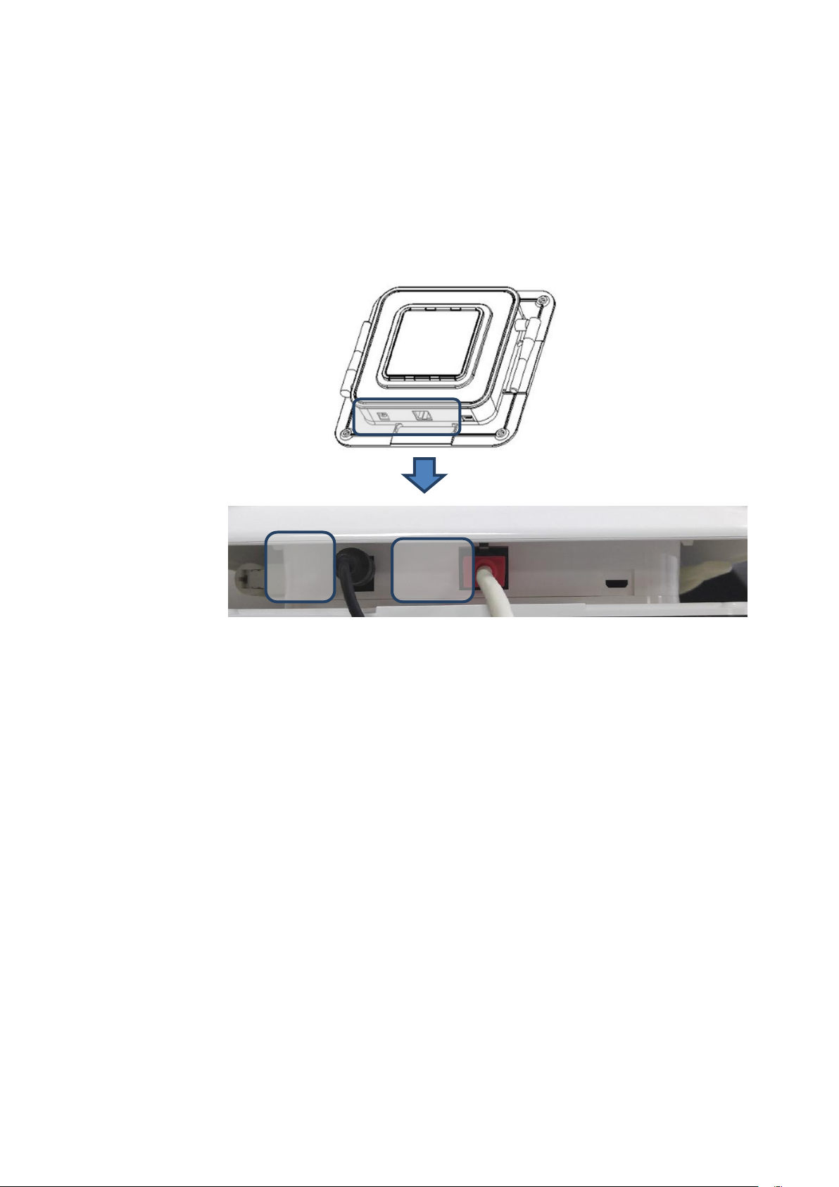
Power Jack
Ethernet Cable
2.3 APCable Connection
① Ethernet Cable Connection
Use an ethernet cable to connect the router and AP.
<Using DC Adaptor>
② Power Cable Connection
When using power adaptor to supply power, use the provided adaptor to connect
to the power port.
You may use a DC adaptor or a PoE injector for AP power.If it is not easy to use
AC power where AP is to be installed, you may use aPoEinjector or PoE switch
hub to supply power only with an ethernet cable. Yet, be careful the length of the
ethernet cable does not exceed 100M.
Page 47
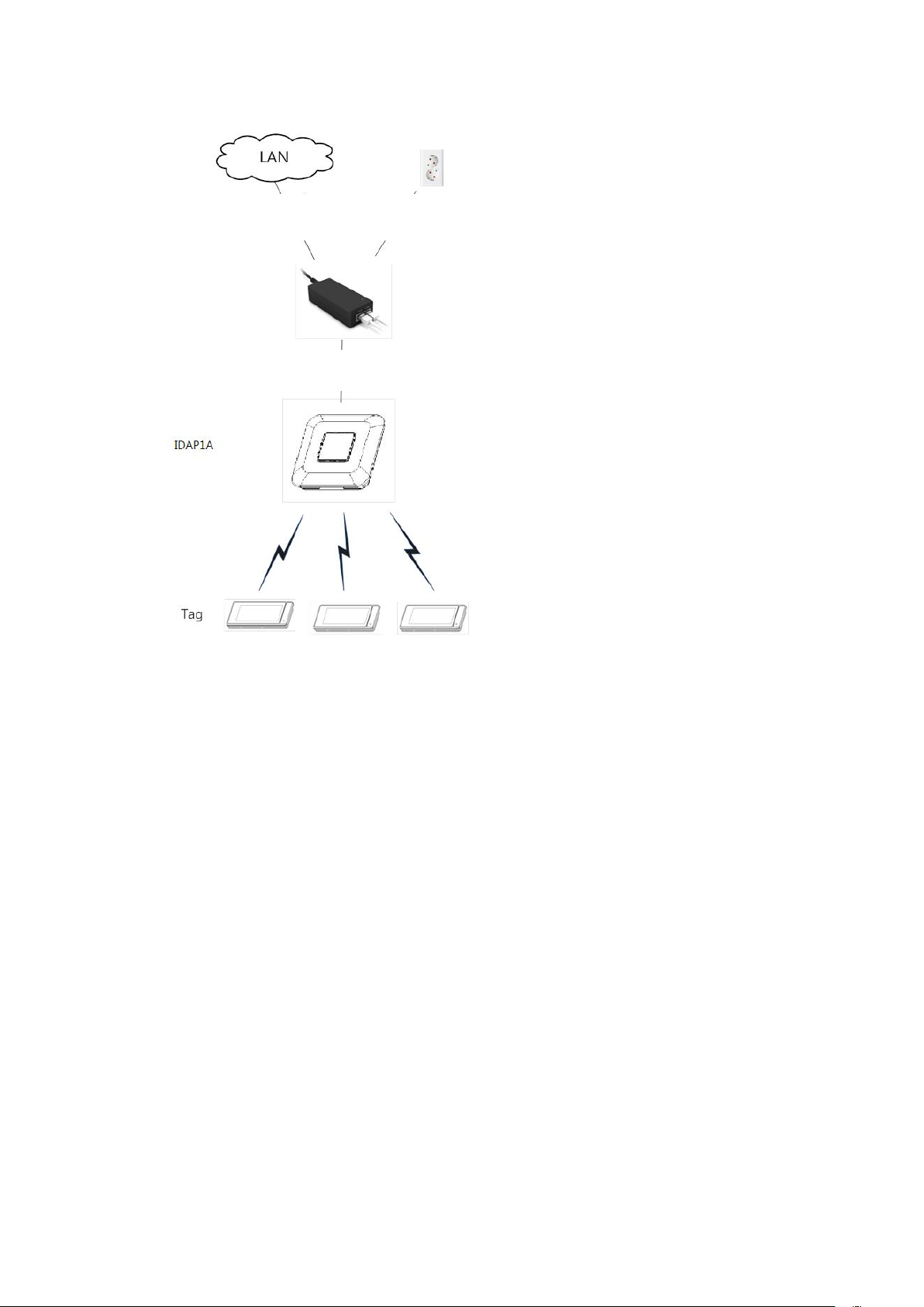
Connect to LAN
Data
Power
PoE Injector
The following is how to connect PoEinjector with the AP.
① Connect the injector power code to the AC socket.
② You can find Data In(LAN) portand Data Out(POE) port on the injector.
③ Use an ethernet cable to connect the router to Data In(LAN).
④ Connect Data Out(PoE) port to AP.
Page 48
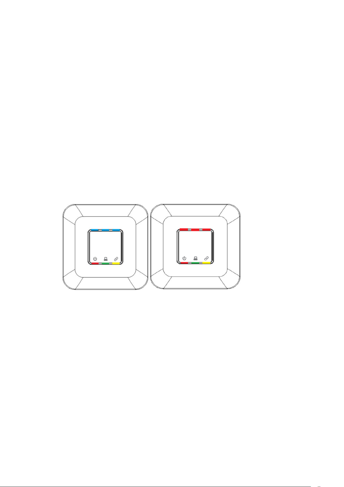
2.4 APFunction Check
You can check the AP status from the 4 LED‟s on the front side.
Red LED
LED is turned on when power is supplied.
Green LED
LED is turned on when connected to network.
Yellow LED
LEDflickers on when communicating with network.
Blue LED / Red LED
Blue LED flickers when AP normally works.
Red LED flickers when an error occurs.
Page 49
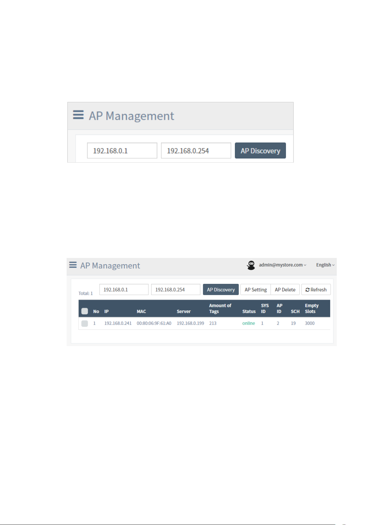
2.5 AP Registration
Log in to ESL client and move toAP Management page.
AP must be connected to the router. Without additional setting, the AP is
voluntarily allocated with an IP via the DHCP of the router.
① Enter the startIPand finishIP.
② Click on [AP Discovery] to search AP.
③ Check the Status is online after AP is found.
Page 50
3. TAGInstallation and Registration
Consider the following when installing TAG.
Do not install nearby industrial equipment including transformer, microwave,
refrigerator, etc. (keep apart more than 5m)
Metal, concrete, wall, etc. blocks communication so signals may be lost.
If the battery is separately delivered without being installed, make sure
batteries are not in contact with each other. (A fire may break out due to
damage of the battery or high temperature.)
Fix the TAG so it does not fall off.
(It may be damaged when fallen.)
If you use a metal tool when separating the battery, the (+) and (-) of the
battery may be shorted, temporarily consumed to a great amount.
3.1 TAG Installation
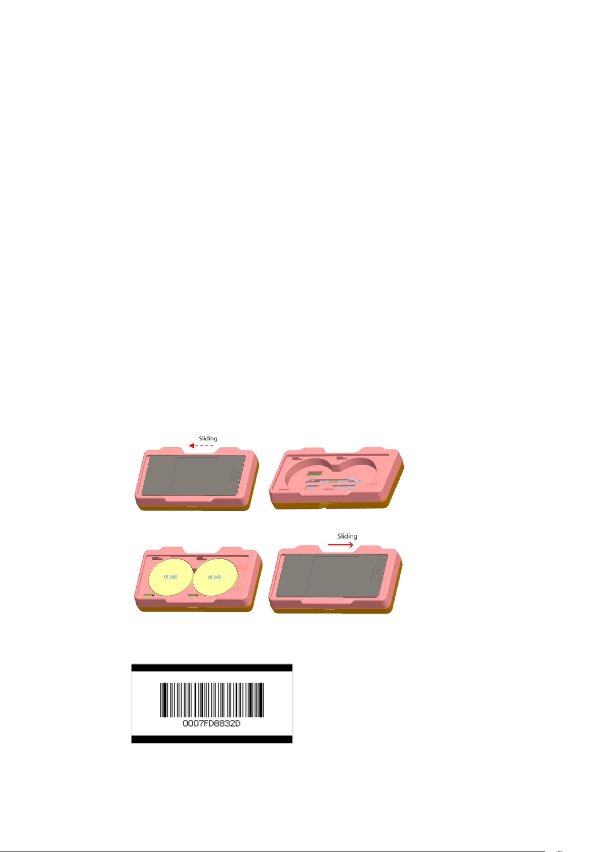
① Open the cover of TAG backside and insert theCoin battery.
The battery isCR2450 type.
② About 30 seconds after TAG is turned on,see if the barcode below is made.
Page 51
You will find no change on the screen if the
APorESLServer is not under operation.In this case, check
the status of AP and ifESLServer is being launched.
The battery is consumed fast when the server or AP
connection is lost, so keep the it connected.
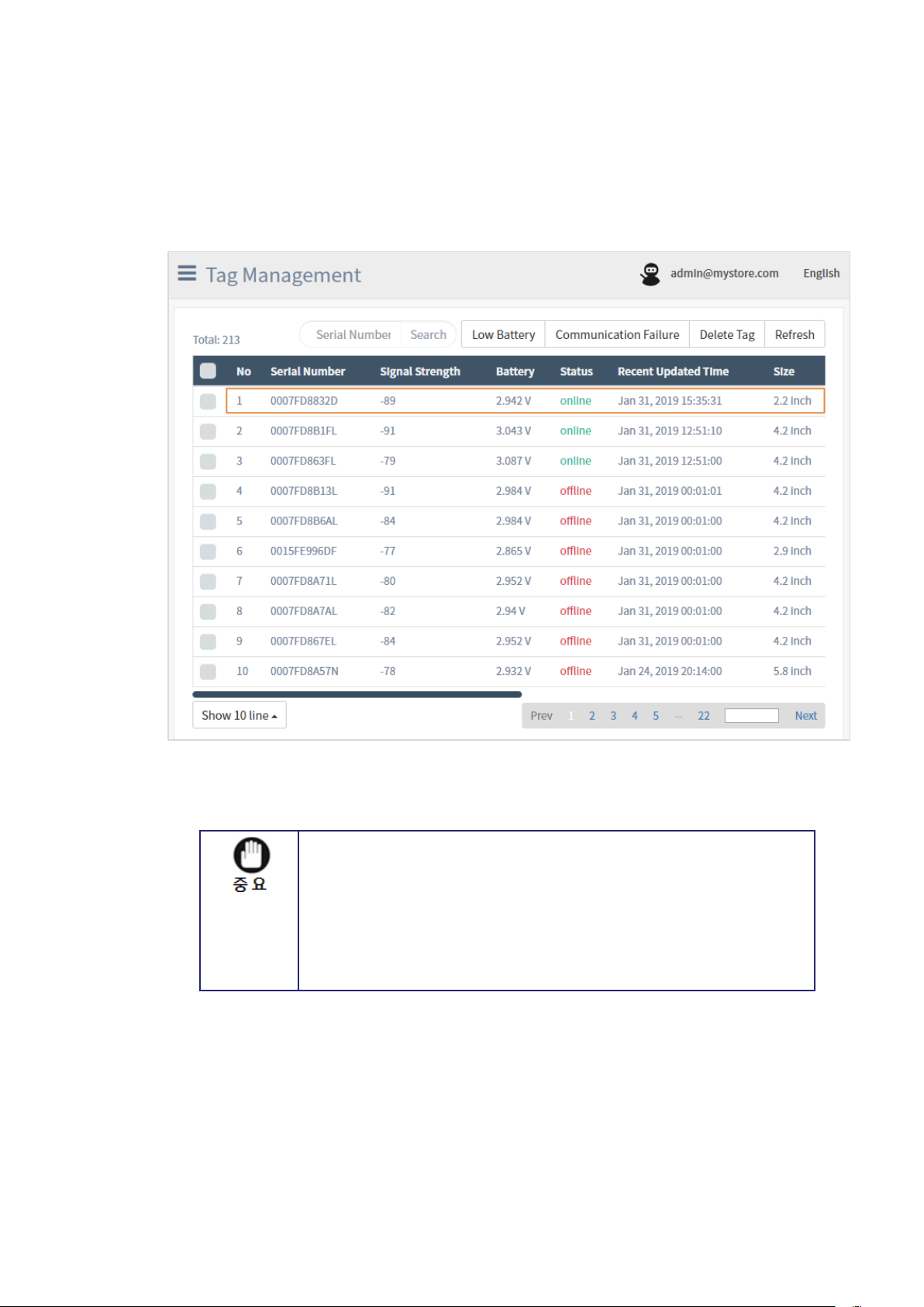
③ Tag Management page after Log in to ESL Client and then move to Tag
Management page.
Find the TAG with Serial Number“0007FD8832D”.
Page 52
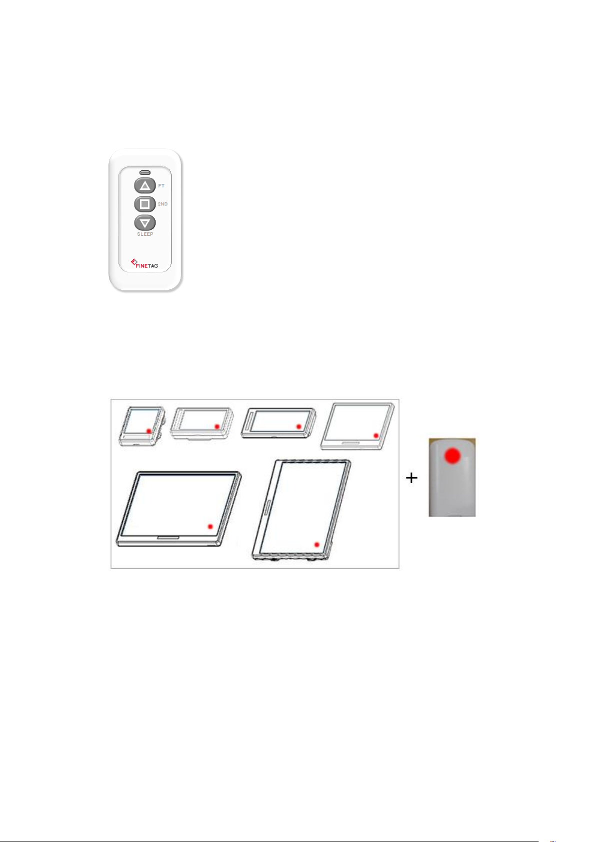
4. Remote Control Usage
The remote control is used for tag reset and shut down.
The tag is reset when the bottom right of the tag and the upper part of the remote-
control backside is in touch.
The tag flickers several times and displays the price and barcode display received from
AP.
(붉은 색으로 표기된 부분을 서로 터치)
Contact the remote control to the tag and press the remote control button every
second.
The button functions as following
△ –Tag S/Nbarcode check button
▽ –Tag shutdown button(when you don‟t want to use the tag)
When the button is pressed, the LED color indicates the following.
LED RED –Turned on when button is pressed.
LED BLUE –Turned on when the remote control is communicated with the tag.
Page 53

FCC Compliance Statement
This device complies with part 15 of the FCC rules. Operation is subject to the following two
conditions: (1) This device may not cause harmful interference, and (2) this device must accept any
interference received, including interference that may cause undesired operation.
FCC Interference Statement
This equipment has been tested and found to comply with the limits for a Class B digital device,
pursuant to part 15 of the FCC Rules. These limits are designed to provide reasonable protection
against harmful interference in a residential installation. This equipment generates, uses and can
radiate radio frequency energy and, if not installed and used in accordance with the instructions,
may cause harmful interference to radio communications. However, there is no guarantee that
interference will not occur in a particular installation. If this equipment does cause harmful
interference to radio or television reception, which can be determined by turning the equipment
off and on, the user is encouraged to correct the interference by one of the following measures:
• Reorient or relocate the receiving antenna.
• Increase the separation between the equipment and receiver.
• Connect the equipment into an outlet on a circuit different from which the receiver is connected.
• Consult the dealer or an experienced radio/TV technician for help.
FCC Caution
Any changes or modifications not expressly approved by the party responsible for compliance could
void the user's authority to operate this equipment. This transmitter must not be co-located or
operating in conjunction with any other antenna or transmitter.
FCC Radiation Exposure Statement
This equipment complies with FCC radiation exposure limits set forth for an uncontrolled
environment. This equipment should be installed and operated with minimum distance 20 cm
between the radiator and your body. This transmitter must not be co-located or operating in
conjunction with any other antenna or transmitter.
 Loading...