


Ultrasonic Wind Sensor
Model: WS80BN
FCC ID: WA5WS80BN
Contents
1. Introduction ......................................................................... 2
2. Get Started ........................................................................... 2
3. Overview ............................................................................. 3
4. Setup Guide ......................................................................... 4
5. Mounting ............................................................................. 5
6. Calibration ........................................................................... 8
7. Wi-Fi Configure with gateway ......................................... 8
6.1 Pair with Gateway or display console ........................ 9
6.2 Wi-Fi Connection ....................................................... 9
8. View Online Data on WS View ........................................... 9
9.Firmware upgrade ............................................................... 10
10. Specification .................................................................... 14

1. Introduction
Thanks for your purchasing this WS80 6-in-1 Ultrasonic
Sensor. This device measures wind speed, wind direction,
temperature, humidity, UV Index and solar radiation. The
Ultrasonic Sensor is solar powered and sends data to the
console via a low-power radio. The data can be streamed by
GW1000 Wi-Fi Gateway (sold separately) or HP2550
console display (sold separately); and can be viewed on our
WS View mobile application after the Wi-Fi configuration
done.
To ensure the best product performance, please read this
manual and retain it for future reference.
The Ultrasonic Sensor is solar powered and sends data to
the console via a low-power radio.
2. Get Started
2.1 Parts List
One 6-in-1 Ultrasonic Sensor
One mounting arm with base
One Set of U-bolts for installation
One User Manual
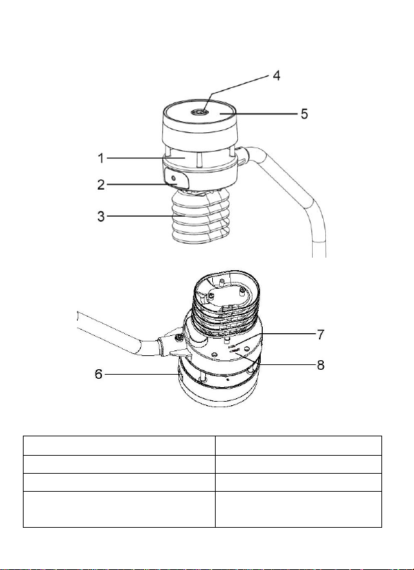
3. Overview
1. Sonic wind sensor
5. Solar Power
2. Battery compartment
6. USB port
3. Temperature & humidity
7. Calibration button
4. Light sensor, LED
indicator
8. Reset button
Figure 1
4. Setup Guide
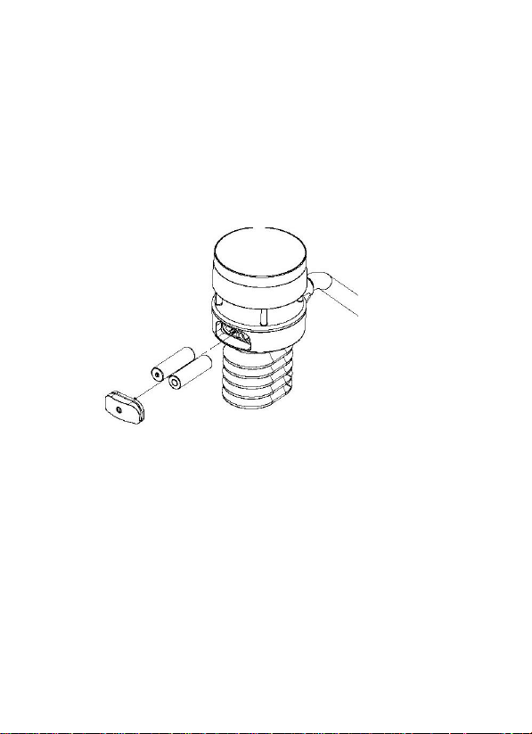
4.1 Install batteries
Insert 2XAA batteries in the battery compartment. The
LED indicator(on the top of the sensor) will turn on for
3 seconds and normally flash once every 4.75 seconds
(the sensor transmission update period).
Figure 2
Note: If no LED light up or is lighted permanently,
make sure the battery is inserted the correct way or a
proper reset is happened. Do not install the batteries
backwards. You can permanently damage the outdoor
sensor
We recommend lithium batteries for cold weather
climates, but alkaline batteries are sufficient for most
climates. We do not recommend rechargeable batteries.
They have lower voltages, do not operate well at wide
temperature ranges, and do not last as long, resulting in
poorer reception.
5. Mounting
Before you mount
Before installing your outdoor sensor in the permanent
location, we recommend operating the device for one week
in a temporary location with easy access. This will allow
you to check out all of the functions, insure proper
operation and familiarize you with the weather station and
calibration procedures.
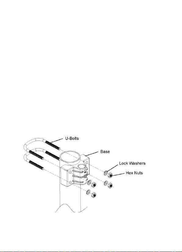
1. Install the base on a pole(1.25inch~2inch) as Figure 3
Figure 3
2. Attaching Arm to Ultrasonic Sensor as Figure 4.

Figure 4
3. Insert the arm into the base as Figure 5. Be sure to
line up the small hole in the arm with the holes in the
base. Insert the machine screw through the holes in
the base and arm.
.
Figure 5

4. There is an arrow icon with ”N” words (Figure
6)representing the direction of North. The sensor body has
to be adjusted so that the “N” indication is facing to real
north direction in your location. A compass device is
recommended to help adjust direction. Permanent wind
direction error will be introduced when the outdoor sensor
is not installed in right direction
Figure 6

8
6. Calibration
The ultrasonic sensor has been calibration before
leaving the factory. We do not recommend that
customers do calibration by themselves.
Customers use this feature only when the wind speed
does not return to zero when there is no wind
After the product works normally, use a cloth or
sponge with good water absorption (prevent the echo
of the ultrasonic waves) to completely wrap the air
inlet.
With an open ended paperclip, press and hold the
CAL button for three seconds, the top LED light will
be on. After releasing the CAL button, place the
product on the table. After five seconds, the top LED
light will flash. At this time it is in the calibration
mode. Wait for the LED to flash, the calibration is
over, and the product automatically enters the normal
working mode.
7. Wi-Fi Configure with gateway
If you want to view the Ultrasonic Sensor data on
your mobile application, you need to pair this device

9
with our GW1000 Wi-Fi Gateway or HP2550 display
console (sold separately).
6.1 Pair with Gateway or display console
Please follow the tips to pair your sensor(s) with the
Wi-Fi Gateway or HP2550 display console:
(1). Power on the gateway first (with USB connection)
or HP2550 display console (with adaptor connection)
(2). Power on the Ultrasonic sensor.
(3). The RF status indicator of the gateway will light
on steady, and light off once when it receives the data
from the optional sensor(s) once.
(4). If work normally, you can forward to the Wi-Fi
connection operation.
6.2 Wi-Fi Connection
For this part, please refer to the manual of the
GW1000 Wi-Fi gateway or HP2550 Wi-Fi Weather
Station.
Any question, please contact the customer service.
8. View Online Data on WS View
When the Wi-Fi configuration is done, you can view
the live data of your rainfall sensor on the WS View
application.

10
9.Firmware upgrade
1. Download and install the Dfuse_Demo_V3.0.6
software. Open the installation path; choose to

11
install the STM32 driver according to the
computer system.
2. After the USB driver is installed, connect the
Ultrasonic sensor to the computer with a USB
cable. In the Device Manager of the computer,
you can see that the USB has been recognized
and the STM Device in DFU Mode

12
3. Open the software DfuSeDemo.exe under the
installation path
4. Select the DFU file, then check the Verify after
download option, and click Upgrade to upgrade
the firmware.

13
1
2
3
5. The upgrade completion interface is as follows.
Click Leave DFU mode and finish the upgrade.

14
10. Specification
Measurement
Range
Accuracy
Resolution
Wind speed
0~40m/s
<10m/s, +/-0.5m/s
0.1M/S
10.1 Wireless Specifications:
Transmission distance in open field: 300m(1000 ft)
Sensor reporting interval: 4.75 seconds
RF Frequency: 915 MHz
10.2 Measurement Specification

15
≥10m/s, +/-5%
Wind
direction
0~359°
±5°
1°
Temperature
40~60℃
±1℃
0.1℃
Humidity
1~99%
±5%
1%
Light
0~300Klux
±15%
10Lux
UVI
1~15
±2
1
10.3 Power consumption
Ultrasonic sensor: 2xAA Alkaline batteries (not
included). The primary power source is the solar panel.
The batteries provide backup power when there is
limited solar energy
11. 7. FCC Statement
Statement according to FCC part 15.19:
This device complies with part 15 of the FCC rules.
Operation is subject to the following two conditions:
1. This device may not cause harmful interference.
2. This device must accept any interference received,
including interference that may cause undesired
operation.
Statement according to FCC part 15.21:
Any changes or Modifications not expressly approved

16
by this company could void the user's authority to
operate the equipment.
Statement according to FCC part 15.105:
NOTE: This equipment has been tested and found to
comply with the limits for a Class B digital device,
pursuant to Part 15 of the FCC Rules. These limits are
designed to provide reasonable protection against
harmful interference in a residential installation. This
equipment generates, uses and can radiate radio
frequency energy and, if not installed and used in
accordance with the instructions, may cause harmful
interference to radio communications.
However, there is no guarantee that interference will
not occur in a particular installation. If this equipment
does cause harmful interference to radio or television
reception, which can be determined
by turning the equipment off and on, the user is
encouraged to try to correct the interference by one or
more of the following measures:
• Reorient or relocate the receiving antenna.
• Increase the separation between the equipment and
receiver.
• Connect the equipment into an outlet on a circuit
different from that to which the receiver is connected.
• Consult the dealer or an experienced radio/TV
technician for help.
 Loading...