

Page 1
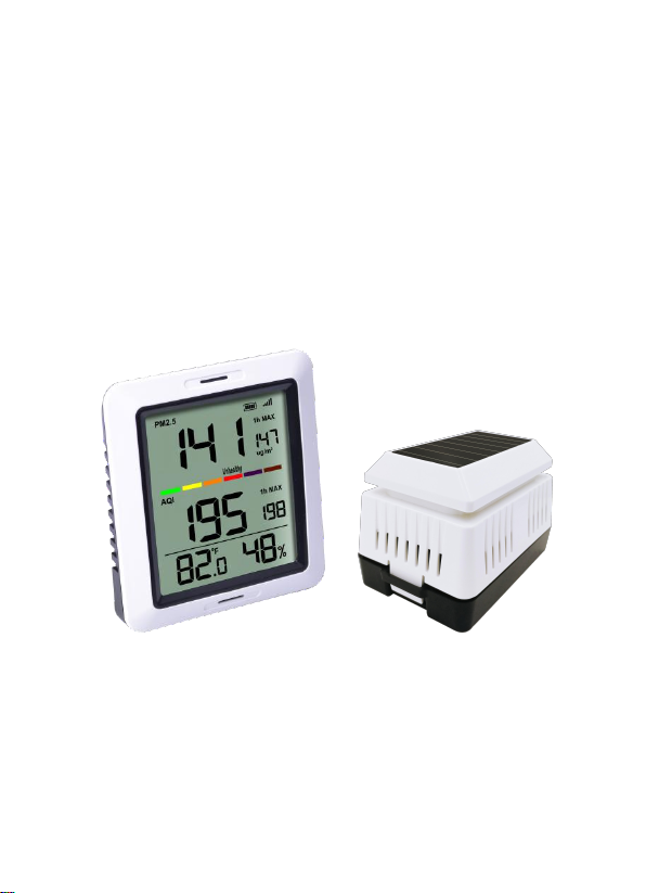
Wireless Air Quality Monitor with
Indoor Temperature and Humidity
Model: WH0290
Page 2

1
Contents
1. Introduction
2. Get Started
2.1 Parts List
2.2 Air Quality Sensor Set Up
2.3 Display Console Set Up
3. Wireless Sensor Installation
4. Console Operation
4.1 °C/°F
4.2 MAX
5. Sensor Resynchronization
6. Best Practices for Wireless Communication
7. Function
8. Appendix
9. Specifications
9.1 Wireless Specifications
9.2 Measurement Specifications
9.3 Power Consumption
10. FCC Statement
11. Warranty Information
...........................................................
...........................................................
....................................................
........................
...........................
2.3.1 Display Console Layout
..............................
..............................................
...........................................................
............................................................
...............................
..............................................................
.............................................................
.....................................................
..............................
................................................
......................................
................
.........................
................
2
2
2
3
5
7
8
9
9
9
10
10
11
12
13
13
13
14
15
17
Page 3

2
1. Introduction
Thanks for your purchasing of the WH0290
Wireless Air Quality Monitor with Indoor
Temperature and Humidity. To ensure the best
product performance, please read this manual
and retain it for future reference.
2. Get Started
Note: P
the order shown in this section (insert batteries
in the Air Quality Monitor first, then
Sensor(transmitter).
Attention:
2.1 Parts List
ower up sequence can be performed in
Do not mix old and new batteries
Do not mix Alkaline, Standard, Lithium or
Rechargeable batteries
Ensure batteries are installed correctly with
regard to polarity +/Please fully charge the included sensor
batteries overnight when first use.
1 One Air Quality Monitor (Receiver)
2 One Air Quality Sensor(Wireless PM2.5
Sensor)
3 One USB Cable
4 One User Manual
Page 4
3
5 Two LSD( low self discharge) Ni-MH
Rechargeable Batteries
2.2 Air Quality Sensor Set Up
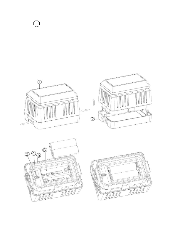
Remove the battery door on the base of the
1.
air quality sensor as shown in Figure 1
Figure 1
Page 5

4
1
Solar panel
2
Battery Compartment Cover
3
Red LED Indicator (RF transmission)
4
Blue LED Indicator (charging status)
5
USB Port
6
Battery Compartment
Insert two AA battery.
2.
After inserting the battery, the remote sensor
3.
LED indicator will light for 4 seconds, and
then flash once per 10 minutes thereafter.
Each time it flashes, the sensor is
transmitting data.
Connect the USB cable to a standard USB
4.
power adapter and charge battery until blue
LED is turned off, indicating batteries are fully
charged.
When no sufficient solar radiation is possible,
5.
a fully charged set battery can last for about
20 days( about 500hours), and battery status
monitor on display will reflect the battery
power status. When battery is empty, please
charge sensor again.
After the batteries are fully charged, remove
6.
the USB cable and close the battery door.
Page 6
5
2.3 Display Console Set Up
1. Move the remote about 2 to 3m away from
the display console (if the sensor is too
close, it may not be received by the display
console).
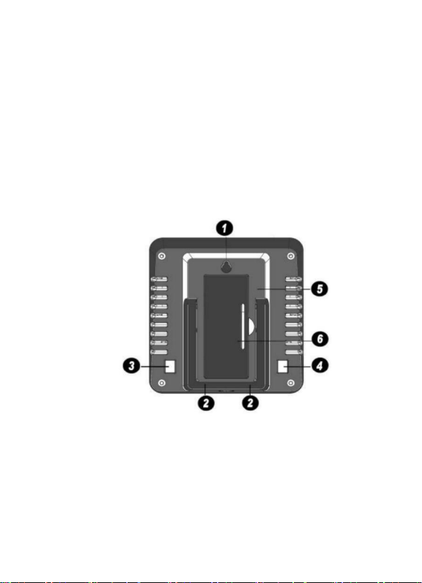
2. Remove the battery door on the back of the
display, as shown in Figure 2. Insert one AA
(alkaline, lithium or rechargeable) battery in
the back of the display console.
Figure 2
1. Integrated Hanging Hole
2. Tabletop Stand
3. °C/°F Button
4. MAX Button
5. Battery Compartment
6. Battery Compartment Cover
Page 7
6
All of the LCD segments will light up for a few
seconds to verify all segments are operating
properly.
Full Display
3. Replace the battery door, and fold out the
desk stand and place the console in the
upright position.
The console will instantly display indoor
temperature and humidity. The PM 2.5
value will update on the display within a few
minutes.
While in the search mode, the reception
search icon flash.
If the remote does not update, please contact
our Customer Service for support.
Page 8
7
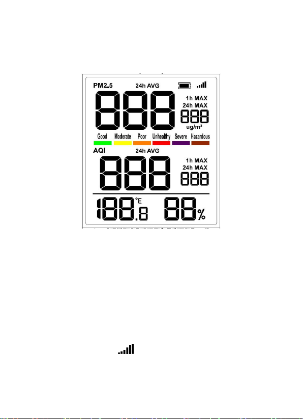
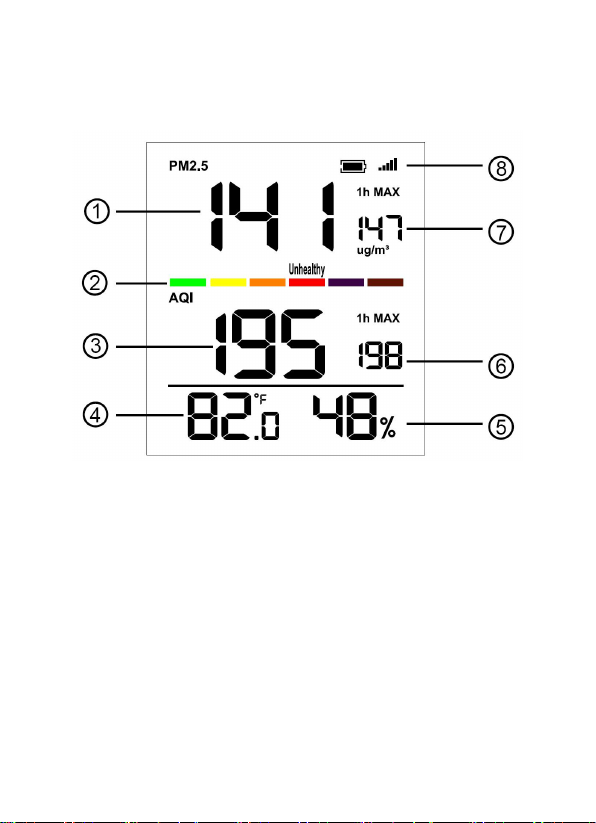
2.3.1 Display Console Layout
Figure 3
1. Current PM2.5 Concentration
2. Air Quality Level
3. Current AQI
4. Indoor Temperature
5. Indoor Humidity
6. 1h Max AQI
7. 1h Max PM2.5 Concentration
8. Outdoor Reception Icon
Page 9
8
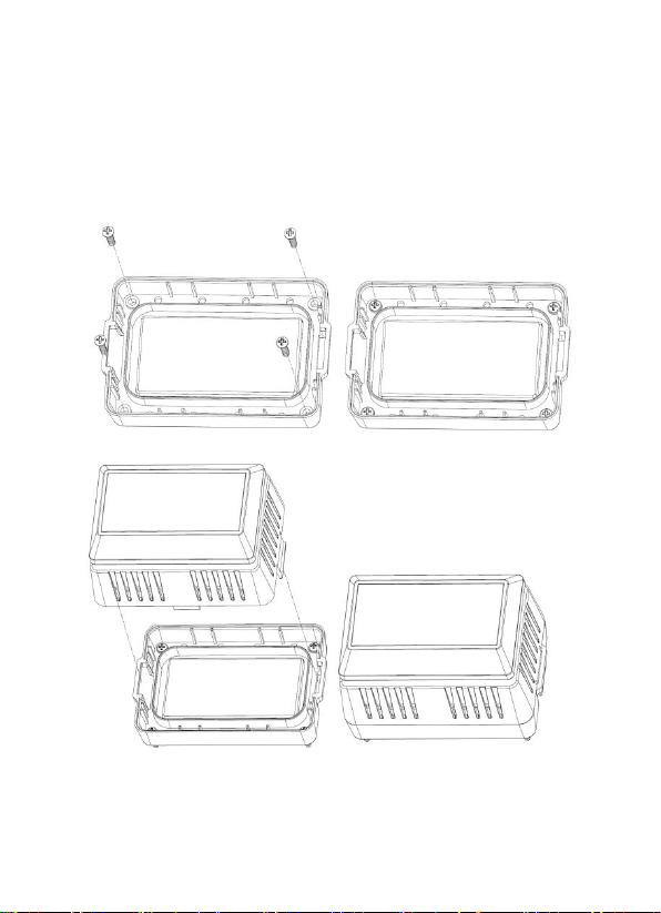
3. Wireless Sensor Installation
Outdoor Installation
Use four screws to fix the base of the outdoor
sensor on a flat surface.
Page 10

9
4. Console Operation
Note: The console has two buttons for easy
operation: 【 °C/°F 】 button (on the left), and
【MAX】button (on the right).
4.1 °C/°F
Short press 【 ° C/ ° F 】 button: switch between
display of temperature unit: °C/°F
Press and hold the 【 ° C/ ° F 】 button for 2
seconds: switch between display of the 24H
average value of the PM2.5 concentration and
AQI.
4.2 MAX
Short press the【MAX】button: switch between
display of the 1h MAX / 24h MAX / MAX(since
last reset) value of the PM2.5 concentration and
AQI.
Press and hold the【MAX】button for 2s to clear
all the 1h MAX / 24h MAX / MAX(since last reset)
value.
Page 11

10
5. Sensor Resynchronization
When the remote sensor lost reception, holding
the °C/°F and MAX button for 5s, will register
new outdoor for 12 minutes.
While in the search mode, the reception search
icon flash.
You can also re-sync the two units by removing
all the batteries and then wait for several
minutes. Then install the batteries again to
register faster.
6. Best Practices for Wireless
Communication
Note: To insure proper communication, place
the remote sensor on a flat surface. Do not lean
or upside down it to avoid any damage.
Keep the console several feet away from
computer monitors and TVs.
Page 12
11
7. Function
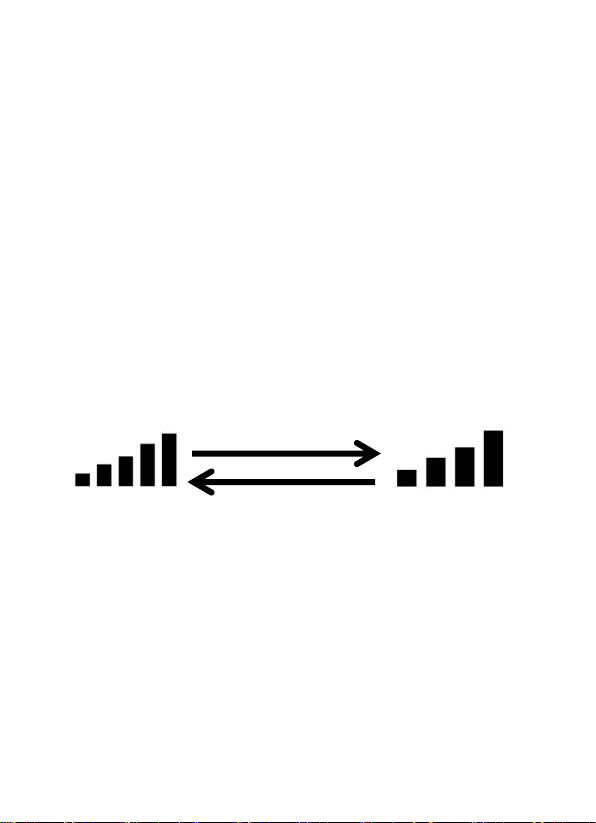
Lost the signal once
Received the signal once
1)Indoor temperature and humidity
2)Every 60 second the unit will measure
indoor temperature and humidity.
3)Display current / 24H average PM 2.5
concentration and AQI.
4)Display 1h MAX / 24h MAX / MAX (since
last reset) PM 2.5 concentration and AQI.
5)Air quality level indicator color bar based on
AQI.
6)IPx4 rainproof sensor, can be used both
indoor and outdoor.
Page 13

12
8. Appendix
AQI
Air Pollution
Level
PM2.5
Concentration
ug/m3
Health Implications
Cautionary Statement
(for PM2.5)
0 - 50
Good
0.0-12.0
Air quality is considered
satisfactory, and air
pollution poses little or
no risk
None
51 -100
Moderate
12.1-35.4
Air quality is
acceptable; however,
for some pollutants
there may be a
moderate health
concern for a very small
number of people who
are unusually sensitive
to air pollution.
Active children and
adults, and people with
respiratory disease,
such as asthma, should
limit prolonged outdoor
exertion.
101-150
Poor
35.5-55.4
Members of sensitive
groups may experience
health effects. The
general public is not
likely to be affected.
Active children and
adults, and people with
respiratory disease,
such as asthma, should
limit prolonged outdoor
exertion.
151-200
Unhealthy
55.5-150.4
Everyone may begin to
experience health
effects; members of
sensitive groups may
experience more
serious health effects
Active children and
adults, and people with
respiratory disease,
such as asthma, should
avoid prolonged outdoor
exertion; everyone else,
especially children,
should limit prolonged
outdoor exertion
201-300
Severe
150.5-250.4
Health warnings of
emergency conditions.
The entire population is
more likely to be
affected.
Active children and
adults, and people with
respiratory disease,
such as asthma, should
avoid all outdoor
exertion; everyone else,
especially children,
should limit outdoor
exertion.
300+
Hazardous
250.5+
Health alert: everyone
may experience more
serious health effects
Everyone should avoid
all outdoor exertion
About the Air Quality Levels
Page 14

13
9. Specifications
Measurement
Range
Accuracy
Resolution
Indoor
temperature
14 to 140 °F
(-10 to 60°C)
± 1 °F
(±1°C)
0.1 °F
(±0.5°C)
Indoor
Humidity
1 to 99 %
Accuracy +/- 3% RH
(@25°C. , 30%RH to
80%RH).
Accuracy +/- 5% RH
(@25°C. , 1%RH
to29%RH;80%RH to
99%RH)
1%
PM 2.5
0~999ug/m3
0~100ug/m3 ±15ug/m3
>100ug/m3 ±15%
1ug/m3
9.1 Wireless Specifications
Line of sight wireless transmission (in
open air): 300feet(100meters)
Frequency: 433/915/868 MHz (optional)
Update Rate: 10 minutes
9.2 Measurement Specifications
The following table provides specifications for
the measured parameters.
Page 15

14
9.3 Power Consumption
Base station (display console) : 1 x AA
Alkaline or Lithium batteries (not included)
Remote sensor : 2 x AA 1.2V LSD type
NI-MH batteries (included)
Solar panel for backup power
Note:
1. Battery type for charging: 2 x AA 1.2V
NI-MH batteries(battery life: 3 weeks)
2. It's recommended to recharge the
outdoor sensor every two week.
3. Charge time: 3h (The blue LED indicator
will light when in charge and be off when full
charged)
4.Charge Method: USB charge(USB Cable
included)
Page 16

15
10. FCC Statement
Statement according to FCC part 15.19:
This device complies with part 15 of the FCC
rules. Operation is subject to the following two
conditions:
1.This device may not cause harmful
interference.
2.This device must accept any interference
received, including interference that may cause
undesired operation.
Statement according to FCC part 15.21:
Any changes or modifications not expressly
approved by this company could void the user's
authority to operate the equipment.
Statement according to FCC part 15.105:
NOTE: This equipment has been tested and
found to comply with the limits for a Class B
digital device, pursuant to Part 15 of the FCC
Rules. These limits are designed to provide
reasonable protection against harmful
interference in a residential installation. This
equipment generates, uses and can radiate
radio frequency energy and, if not installed and
used in accordance with the instructions, may
cause harmful interference to radio
communications.
However, there is no guarantee that interference
will not occur in a particular installation. If this
equipment does cause harmful interference to
Page 17

16
radio or television reception, which can be
the no-collocation statement.
determined
by turning the equipment off and on, the user is
encouraged to try to correct the interference by
one or more of the following measures:
• Reorient or relocate the receiving antenna.
• Increase the separation between the
equipment and receiver.
• Connect the equipment into an outlet on a
circuit different from that to which the receiver is
connected.
• Consult the dealer or an experienced radio/TV
technician for help.
This device complies with FCC radiation
exposure limits set forth for an uncontrolled
environment and it also complies with Part 15 of
the FCC RF Rules. This equipment must be
installed and operated in
accordance with provided instructions and the
antenna(s) used for this transmitter must be
installed to provide a separation distance of at
least 20 cm from all persons and must not be
co-located or operating in conjunction with any
other antenna or transmitter. End-users and
installers must be provided with antenna
installation instructions and consider removing
Page 18

17
11. Warranty Information
We disclaim any responsibility for any
technical error or printing error, or their
consequences.
All trademarks and patents are recognized.
We provide a 1-year limited warranty on this
product against manufacturing defects in
materials and workmanship.
This limited warranty begins on the original date
of purchase, is valid only on products purchased
and only to the original purchaser of this product.
To receive warranty service, the purchaser must
contact us for problem determination and service
procedures.
This warranty covers only actual defects within
the product itself, and does not cover the cost of
installation or removal from a fixed installation,
normal set-up or adjustments, claims based on
misrepresentation by the seller or performance
variations resulting from installation-related
circumstances.
 Loading...