


QTY
Item
1
Display Console
Frame Dimensions (LxHxW): 3 x 3.5 x 1 in
LCD Dimensions (LxW): 2.5 x 2.25"
Wireless Indoor / Outdoor Thermometer with
Indoor Humidity User Manual
Sensor model :WH19 Receiver model: WH0270
Table of Contents
1 Introduction ..................................................................................................................................... 1
2 Getting Started ................................................................................................................................ 1
2.1 Parts List ................................................................................................................................. 1
2.2 Recommend Tools .................................................................................................................. 2
2.3 Thermometer Sensor Set Up .................................................................................................. 2
2.4 Display Console Set Up ......................................................................................................... 2
2.4.1 Display Console Layout ..................................................................................................... 4
2.4.2 Sensor Operation Verification ............................................................................................ 4
3 Remote Sensor Installation ............................................................................................................. 4
4 Console Operation........................................................................................................................... 5
4.1 Temperature Units of Measure ............................................................................................... 5
4.2 High Low Record ................................................................................................................... 5
4.3 Sensor Resynchronization ...................................................................................................... 5
4.3.1 Best Practices for Wireless Communication ...................................................................... 5
5 Glossary of Terms ........................................................................................................................... 6
6 Specifications .................................................................................................................................. 6
6.1 Wireless Specifications .......................................................................................................... 6
6.2 Measurement Specifications ................................................................................................... 6
6.3 Power Consumption ............................................................................................................... 6
7 Troubleshooting Guide .................................................................................................................... 6
8 Liability Disclaimer ........................................................................................................................ 7
9 FCC Statement ................................................................................................................................ 8
1 Introduction
Thank you for your purchase of the Weather Wireless Indoor/Outdoor Thermometer with
Indoor Humidity. The following user guide provides step by step instructions for installation,
operation and troubleshooting.
2 Getting Started
Note: The power up sequence must be performed in the order shown in this section (insert
batteries in the remote transmitter(s) first, Display Console second).
The WH0270 weather station consists of a display console (receiver), and a thermometer (remote
transmitter).
2.1 Parts List
Version 1.0 Page 1
LCD Segment Height: 0.75 inch
1
Thermometer transmitter (WH19)
Dimensions (LxHxW): 2.75” x 1.75” x 0.75”
1
User Manual
1
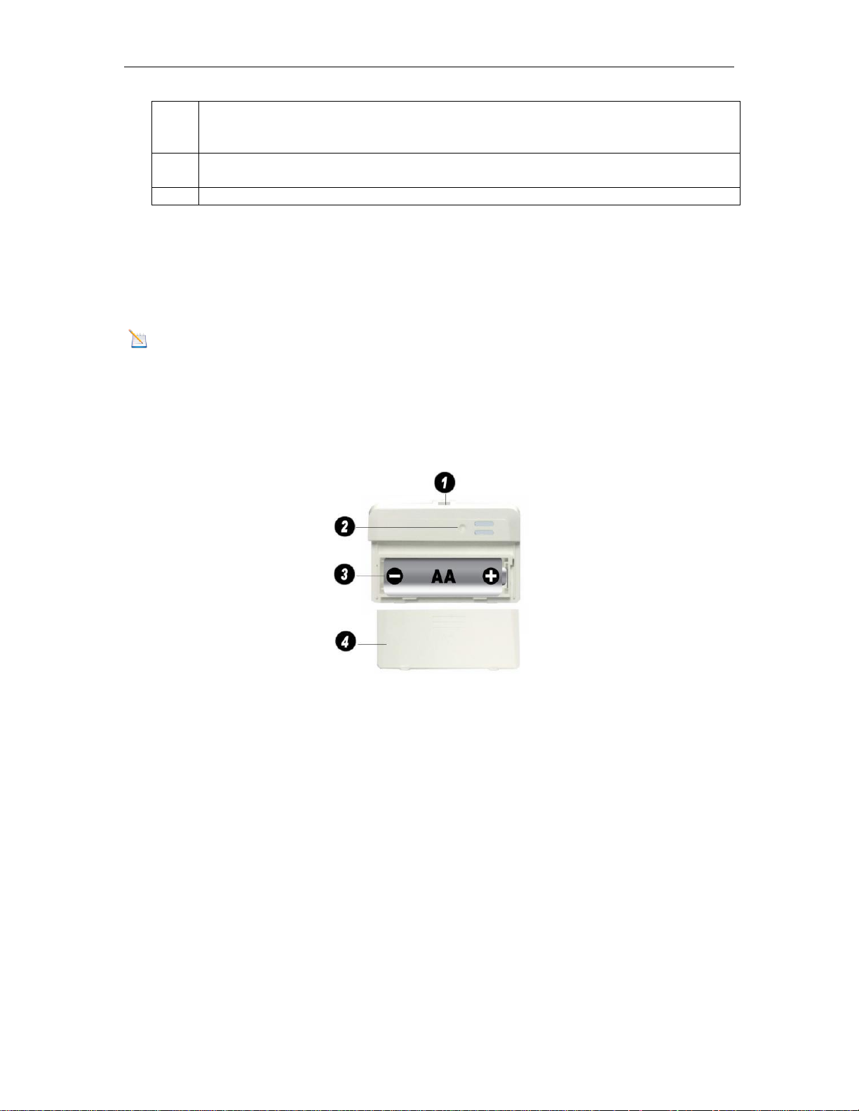
Integrated hanger for zip tie
2
Wireless transmitter LED
3
AA Battery
4
Battery Compartment Cover
2.2 Recommend Tools
Hammer for hanging remote thermometer transmitter.
2.3 Thermometer Sensor Set Up
Note: Do not use rechargeable batteries. They tend to have a lower operating voltage, do not have
a wide temperature range, and do not last as long as non-rechargeable batteries.
We recommend fresh alkaline batteries for outdoor temperature ranges between -4 °F and 140 °F and
fresh lithium batteries for outdoor temperature ranges between -40 °F and 140 °F .
1. Remove the battery door on the back of the sensor by sliding the compartment door down, as
shown in Figure 1 .
2. Insert one AA battery.
3. After inserting the battery, the remote sensor LED indicator will light for 4 seconds, and then
flash once per 60 seconds thereafter. Each time it flashes, the sensor is transmitting data.
4. Close the battery door.
2.4 Display Console Set Up
1. Move the remote thermometer(s) about 5 to 10’ away from the display console (if the sensor
is too close, it may not be received by the display console).
2. Remove the battery door on the back of the display, as shown in Figure 2. Insert one AA
(alkaline or lithium, avoid rechargeable) battery in the back of the display console.
Version 1.0 Page 2
Figure 1
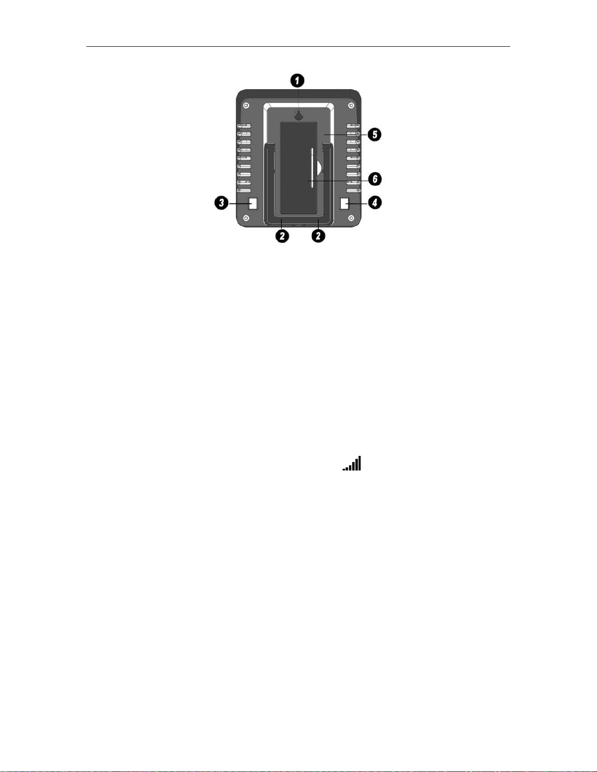
1
Suspension eye for wall hanging
2
Desk Stand
3
°C / °F button
4
High / Low Record button
5
Battery Compartment
6
Battery Compartment door
Figure 2
All of the LCD segments will light up for a few seconds to verify all segments are operating properly.
3. Replace the battery door, and fold out the desk stand and place the console in the upright
position.
The console will instantly display indoor temperature and humidity. The remote
temperature will update on the display within a few minutes.
While in the search mode, the reception search icon flash.
If the remote does not update, please reference the troubleshooting guide in Section 7.
Version 1.0 Page 3

1
Outdoor Temperature
2
Indoor Temperature
3
Indoor Humidity
4
Outdoor Temperature High / Low Record
5
Indoor Temperature High / Low Record
6
Indoor Humidity High / Low Record
7
Wireless Reception Icon
2.4.1 Display Console Layout
Figure 3
2.4.2 Sensor Operation Verification
Verify the indoor and outdoor temperature match closely with the console and sensor array in the same
location (about 5 to 10’ apart). The sensors should be within 2°F (the accuracy is ± 1°F ). Allow
about 30 minutes for both sensors to stabilize.
3 Wireless Sensor Installation
It is recommended you mount the remote sensor in a shaded area. Direct sunlight and radiant heat
sources will result in inaccurate temperature readings. Although the sensor is water resistant, it is best
to mount in a well-protected area, such as under an eve.
3.1 Mounting with Zip Tie
Version 1.0 Page 4
Figure 4

Medium
RF Signal Strength Reduction
Glass (untreated)
5-15%
Plastics
10-15%
Wood
10-40%
Brick
10-40%
4 Console Operation
Note: The console has two buttons for easy operation: °C / °F button (on the left), and High /
Low Record button (on the right).
4.1 Temperature Units of Measure
To change the temperature units of measure, press the C / °F button (on the left).
4.2 High Low Record
The indoor temperature, indoor humidity, and outdoor temperature can be reset every 24 hours (based
on when the batteries are inserted), or never.
Press the High / Low Record button (on the right) to switch between reset 24 hours or never.
To reset the highs and lows, remove and reinsert the battery inside the console. If Reset 24 hour option
is selected, the highs and lows will reset 24 hours after the battery is inserted.
4.3 Sensor Resynchronization
If the remote sensor is lost, dashes will be displayed. To resynchronize, press both the °C / °F and
High / Low Record buttons at the same time for five seconds.
While in the search mode, the reception search icon flash.
4.3.1 Best Practices for Wireless Communication
Note: To insure proper communication, mount the remote sensor on a vertical surface, such as a
wall. Do not lay the sensor flat.
Wireless communication is susceptible to interference, distance, walls and metal barriers. We
recommend the following best practices for trouble free wireless communication.
1. Electro-Magnetic Interference (EMI). Keep the console several feet away from computer
monitors and TVs.
2. Radio Frequency Interference (RFI). If you have other 433 MHz devices and
communication is intermittent, try turning off these other devices for troubleshooting
purposes. You may need to relocate the transmitters or receivers to avoid intermittent
communication.
3. Line of Sight Rating. This device is rated at 300 feet line of sight (no interference, barriers or
walls) but typically you will get 100 feet maximum under most real-world installations,
which include passing through barriers or walls.
4. Metal Barriers. Radio frequency will not pass through metal barriers such as aluminum
siding. If you have metal siding, align the remote and console through a window to get a clear
line of sight.
The following is a table of reception loss vs. the transmission medium. Each “wall” or obstruction
decreases the transmission range by the factor shown below.
Version 1.0 Page 5

Concrete
40-80%
Metal
90-100%
Term
Definition
Accuracy
Accuracy is defined as the ability of a measurement to match the actual
value of the quantity being measured.
Hygrometer
A hygrometer is a device that measures relative humidity. Relative
humidity is a term used to describe the amount or percentage of water
vapor that exists in air.
Range
Range is defined as the amount or extent a value can be measured.
Measurement
Range
Accuracy
Resolution
Indoor Temperature
14 to 140 °F
± 1 °F
0.1 °F
Outdoor Temperature
-40 to 140 °F
± 1 °F
0.1 °F
Indoor Humidity
1 to 99 %
± 3% (only guaranteed
between 20 to 90%)
1 %
Problem
Solution
Wireless remote (thermometer) not
reporting in to console.
There are dashes (--.-) on the display
console.
If sensor communication is lost, dashes (--.-) will be
displayed on the screen. To reacquire the signal, To
resynchronize, press both the °C / °F and High / Low
Record buttons at the same time for five seconds., and
the remote search icon will flash. Once the signal
5 Glossary of Terms
6 Specifications
6.1 Wireless Specifications
Line of sight wireless transmission (in open air): 265 feet, 100 feet under most conditions.
Frequency: 433 MHz
Update Rate: 48 seconds
6.2 Measurement Specifications
The following table provides specifications for the measured parameters.
6.3 Power Consumption
Base station (display console) : 1 x AA Alkaline or Lithium batteries (not included)
Remote sensor : 1 x AA 1.5V Alkaline or Lithium batteries (not included)
Battery life: About 2 years for base station with one sensor and excellent reception.
Intermittent reception and multiple sensors may reduce the battery life.
Minimum 12 months for thermometer sensor (use lithium batteries in cold weather climates
less than -4 °F )
7 Troubleshooting Guide
Version 1.0 Page 6

Problem
Solution
is reacquired, the remote search icon will turn on,
and the current values will be displayed.
The maximum line of sight communication range is 265’
and 100’ under most conditions. Move the sensor
assembly closer to the display console.
If the sensor assembly is too close (less than 5’), move
the sensor assembly away from the display console.
Make sure the remote sensor transmitter light is flashing
once per 60 seconds.
Install a fresh set of batteries in the remote thermometer.
For cold weather environments, install lithium batteries.
Make sure the remote sensors are not transmitting
through solid metal (acts as an RF shield), or earth
barrier (down a hill).
Move the display console around electrical noise
generating devices, such as computers, TVs and other
wireless transmitters or receivers.
Move the remote sensor to a higher location. Move the
remote sensor to a closer location.
Temperature sensor reads too high in the
day time.
Make sure the thermometer is mounted in a shaded area
on the north facing wall.
Indoor and Outdoor Temperature do not
agree
Allow up to one hour for the sensors to stabilize due to
signal filtering. The indoor and outdoor temperature
sensors should agree within 2 °F (the sensor accuracy is
± 1 °F ).
Use the calibration feature to match the indoor and
outdoor temperature to a known source.
Display console contrast is weak
Replace console batteries with a fresh set of batteries.
8 Liability Disclaimer
Please help in the preservation of the environment and return used batteries to an authorized depot.
The electrical and electronic wastes contain hazardous substances. Disposal of electronic waste in
wild country and/or in unauthorized grounds strongly damages the environment.
Reading the “User manual” is highly recommended. The manufacturer and supplier cannot accept any
responsibility for any incorrect readings and any consequences that occur should an inaccurate reading
take place.
This product is designed for use in the home only as indication of weather conditions. This product is
not to be used for medical purposes or for public information.
The specifications of this product may change without prior notice.
Version 1.0 Page 7

This product is not a toy. Keep out of the reach of children.
No part of this manual may be reproduced without written authorization of the manufacturer.
9 FCC Statement
Statement according to FCC part 15.19:
This device complies with part 15 of the FCC rules. Operation is subject to the following two
conditions:
1. This device may not cause harmful interference.
2. This device must accept any interference received, including interference that may cause
undesired operation.
Statement according to FCC part 15.21:
Modifications not expressly approved by this company could void the user's authority to operate the
equipment. Changes or modifications not expressly approved by the party responsible for compliance
could void the user's authority to operate the equipment.
Statement according to FCC part 15.105:
NOTE: This equipment has been tested and found to comply with the limits for a Class B digital
device, pursuant to Part 15 of the FCC Rules. These limits are designed to provide reasonable
protection against harmful interference in a residential installation. This equipment generates, uses and
can radiate radio frequency energy and, if not installed and used in accordance with the instructions,
may cause harmful interference to radio communications.
However, there is no guarantee that interference will not occur in a particular installation. If this
equipment does cause harmful interference to radio or television reception, which can be determined
by turning the equipment off and on, the user is encouraged to try to correct the interference by one or
more of the following measures:
• Reorient or relocate the receiving antenna.
• Increase the separation between the equipment and receiver.
• Connect the equipment into an outlet on a circuit different from that to which the receiver is
connected.
• Consult the dealer or an experienced radio/TV technician for help.
Version 1.0 Page 8
 Loading...