

Page 1
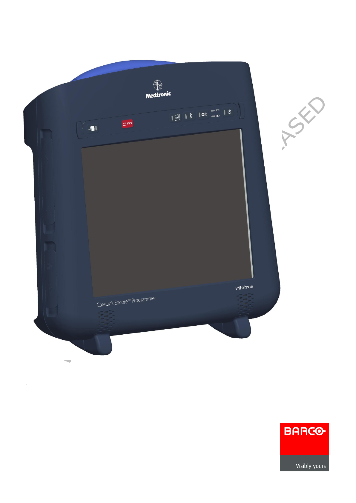
FIMI Computing Platform
NGP1
FCP NGP1 CP12L - MDT
User Manual
Page 2

Contents
FCP NGP1 CP12L - MDT 1
1 Important 5
1.1 Copyright ____________________________________________________________ 5
1.2 Definitions, Acronyms, Terms, and Abbreviations _____________________________ 5
1.3 Safety and precautions __________________________________________________ 7
1.3.1 Intro __________________________________________________________________ 7
1.3.2 Read and follow these instructions when connecting and using your NGP1 Computing
Platform 7
1.3.3 Installation Locat ions _____________________________________________________ 8
1.3.4 Setup precautions ________________________________________________________ 8
1.4 FCC notice ____________________________________________________________ 9
1.4.1 Cables _________________________________________________________________ 9
1.5 FCC Radiation Exposure Statement ________________________________________ 9
1.6 Industry Canada notice __________________________________________________ 9
1.7 Approved for medical applications ________________________________________ 10
1.8 How to read this manual ________________________________________________ 10
1.8.1 Symbols _______________________________________________________________ 10
1.9 Biological Hazard and Returns ___________________________________________ 12
2 The FCP -NG P 1 Com put ing Platform 13
2.1 Introduction _________________________________________________________ 13
2.2 Overview ____________________________________________________________ 14
2.2.1 Dimensions (in mm) _____________________________________________________ 14
2.2.2 Battery dimensions (in mm) _______________________________________________ 15
2.2.3 Weight ________________________________________________________________ 15
2.2.4 Features and connectivity ________________________________________________ 16
2.2.5 Buttons, indicators, ______________________________________________________ 20
3 Getti ng started 21
3.1 Pre requisites ________________________________________________________ 21
3.1.1 Insert the battery _______________________________________________________ 21
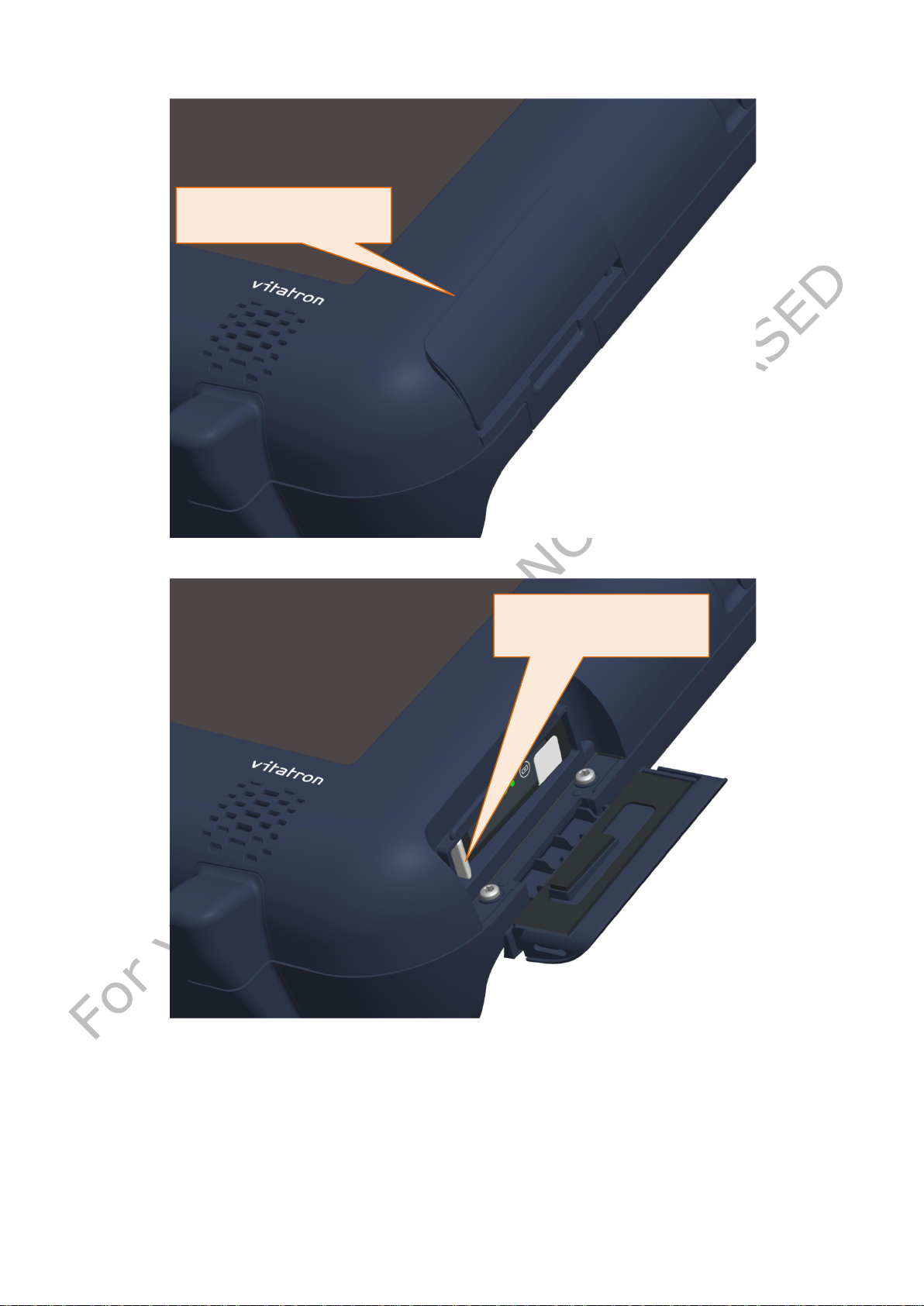
Lift the door up by pressing upward on the battery door recess ______________________ 21
After hearing a click and with the door fully pulled up rotate clockwise the door ________ 22
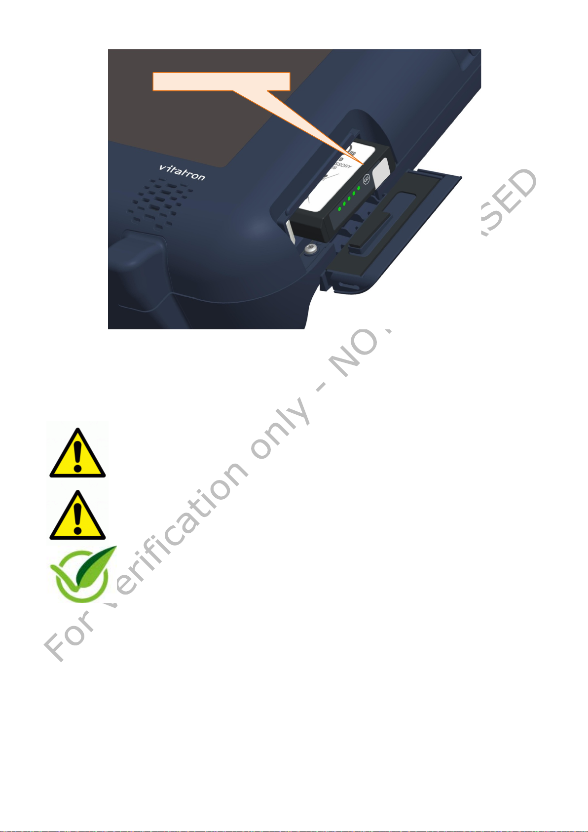
Push the white hook fully downwards till the battery pack is released _________________ 22
Battery removal slip ________________________________________________________ 23
3.1.2 Connect the AC adapter __________________________________________________ 24
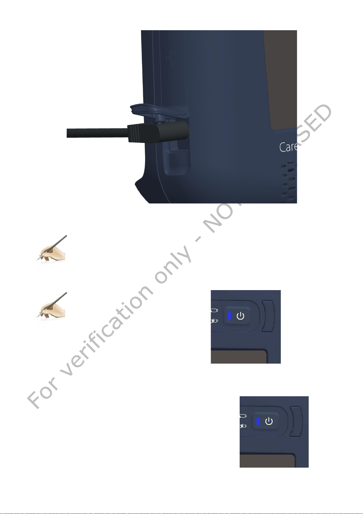
3.1.3 Turning the system on ___________________________________________________ 25
3.1.4 Charging the battery _____________________________________________________ 26
3.1.5 Battery pack indicators ___________________________________________________ 27
Dual function LED indicators _________________________________________________ 27
Battery charge / life monitor button ___________________________________________ 27
4 Us ing your NGP1 Computing Platform 28
4.1 Booting the system ____________________________________________________ 28
4.2 Connecting external peripherals __________________________________________ 28
4.2.1 External Monitor Connection _______________________________________________ 29
VERIFICATION ONLY 2 NOT RELEASED
Page 3

4.2.2 USB doors _____________________________________________________________ 30
4.2.3 Ethernet connection _____________________________________________________ 31
Orange LED : _____________________________________________________________ 31
Transmitting / receiving _____________________________________________________ 31
Green LED : Connected _____________________________________________________ 31
4.2.4 Express Card slot _______________________________________________________ 32
5 NG P 1 Com put ing Platform features 33
5.1 Display _____________________________________________________________ 33
5.2 Touch screen _________________________________________________________ 33
5.3 Using your stylus pen __________________________________________________ 33
5.3.1 Pen characteristics ______________________________________________________ 33
5.4 Using the RF-ID reader _________________________________________________ 33
5.5 Using the Wi-Fi (802-11 ABGN) __________________________________________ 35
5.6 Using the Bluetooth ___________________________________________________ 36
5.7 Using the Waveform Viewer (WFV) button and the Emergency Hot Key (EHK) ______ 37
5.8 Audio solution ________________________________________________________ 37
5.9 Docking connector ____________________________________________________ 38
5.10 Security _____________________________________________________________ 39
5.10.1 Built-in features _________________________________________________________ 39
5.11 Power adapter ________________________________________________________ 39
5.12 Battery _____________________________________________________________ 40
5.12.1 Storing main batteries ____________________________________________________ 42
5.12.2 Battery and energy management. __________________________________________ 42
6 NGP1 Computing Platform Maintenance 43
6.1 Cleaning ____________________________________________________________ 43
6.1.1 Tested substances _______________________________________________________ 43
6.1.2 To clean the screen ______________________________________________________ 43
6.1.3 To clean the cabinet: _____________________________________________________ 44
6.1.4 To clean the fan_________________________________________________________ 44
6.2 Disposal _____________________________________________________________ 44
6.2.1 General warning ________________________________________________________ 44
6.2.2 For Countries in the European Union ________________________________________ 44
6.2.3 For countries outside the European Union ____________________________________ 44
6.2.4 Disposal of your NGP1 Computing Platform ___________________________________ 44
6.2.5 Dispose of Lithium ion battery (Li-ion) _______________________________________ 45
6.2.6 Dispose of coin battery inside of the NGP1 Computing Platform (Mounted on main board):45
7 Troubleshooting 46
7.1 My NGP1 Computing Platform is not turning ON. _____________________________ 46
7.2 My NGP1 Computing Platform Power on LED is ON, but nothing happens. _________ 46
7.3 My NGP1 Computing Platform does not run smoothly _________________________ 46
7.4 How do I turn off my NGP1 Computing Platform _____________________________ 46
7.5 When I use the touch screen. ____________________________________________ 46
7.5.1 the cursor is not following the pen movement. _________________________________ 46
7.5.2 . the system does not respond to taps._______________________________________ 46
8 Specification 47
8.1 System Specifications __________________________________________________ 47
VERIFICATION ONLY 3 NOT RELEASED
Page 4

8.2 Display _____________________________________________________________ 47
8.3 Connectivity and Controls _______________________________________________ 47
8.4 Docking Station Connectivity ____________________________________________ 48
8.5 Power ______________________________________________________________ 48
8.6 Physical Characteristics _________________________________________________ 48
8.7 Optional Configurations ________________________________________________ 48
8.8 Environmental Specifications ____________________________________________ 48
8.9 Applicable International Standards ________________________________________ 49
9 Options 50
9.1 Docking station _______________________________________________________ 50
9.2 Optional additional battery pack _________________________________________ 50
9.3 Optional spare AC adapter ______________________________________________ 50
10 Cus t om e rs care and warranty 50
10.1 Contacts ____________________________________________________________ 50
11 Labels and stickers 51
12 Y our notes 52
Tables
Table 1 - Terms and Acronyms 5
Table 2 – Table of symbols used in this manual 10
Table 3 – Symbols used in the Product label 11
Table 4 – Button primary FW functionality description 20
Table 5 - Status and battery conditions vs. NGP1 Computing Platform status 26
Table 6 - Connector layout specifications 38
Table 7 - Table of tested substances 43
VERIFICATION ONLY 4 NOT RELEASED
Page 5

Term/Acronym
Definition/Usage
FCP - NGP1
FIMI Computing Platform – New Generation programmer 1.
In this manua l is also referred as NGP1 Computing Platform
BIOS
Basic Input Output System: the lowest level software
(firmware) used to run a computing system.
system hang where the application software is no longer
the screen with a blue backgrou nd.
CP
Computing Platfor m
Desktop
The software user interface presented to the user when a
specific device application is not a c tive or loaded.
EHK
Emergency Hard Key – A physical button that causes delivery
of “emergency” thera py.
EMC
Electromagnetic Compatibility
Express Card
External port for connectivity options. Uses a PCIe and USB
interface. Typically u s ed for GSM / £g / Storage media etc.
FW
Firmware
HW
Hardware
HDD
Hard Disk Drive
ID
Identification
IP
Ingress Protection
IEC
International Electro-technical Commission
1 Important
1.1 Copyright
This manual is copyrighted with all rights reserved. Under the copyrights law, this manual
may not be copied, in whole or part, without written consent of FIMI Barco. Under the law,
copying includes translating into another language or format. The device described in this
manual, has been certified/registered by the safety agencies/regulatory authorities as
model number CP12L-MDT
Bluetooth is a registered trademark owned by the Bluetooth SIG, Inc., U.S.A..
Wi-Fi is a registered trademark of the Wi-Fi Alliance.
FIMI Barco has made every effort to identify trademarked properties and owners on this
page. All brands and product names use d in this document are for identification purposes
only and may be trademarks or registered trademarks of their respective companies.
1.2 Definitions, Acronyms, Terms, and Abbreviations
The following acronyms, terms, and abbreviations are used in this and subordinate documents.
Table 1 - Terms and Acronyms
Blue Screen Refers to an unintentional application crash, system erro r, or
available to the user. Typically di splays an error message on
VERIFICATION ONLY 5 NOT RELEASED
Page 6

Term/Acronym
Definition/Usage
IEEE
Institute of Elec tr ical and Electronic Engineers
LCD
Liquid Cristal Disp la y
Medtronic Inc. or MDT
Refers, in this document, to the Cardiac Rhythm Management
business unit which produce implantable cardiovascular
devices (i.e. pacemakers, implantable defibrillators, pacing
leads).
MPI
Medtronic Patient Interface (includes functions that connect
the CP to the patient such as ECG and device telemetry).
Operational Service Lifetime
Availability Lif etime + Service Lifetime
OS
Operating System
PCIe
Peripheral Component Interconnect Express. Used by the
Express Card interface.
RF
Radio Frequency
SN#
Serial Number
SSD
Solid State (Disk) Drive
SW
Software
TCO
Total Cost of Owne r s hip
TPM
Trusted Platform Module (TPM) is both the name of a
published specification detailing a secure cryptographic
processor that can store cryptographic keys that protect
information, as well as the general name of implementations
Security Device"
USB
Universal Seria l Bus
VGA
Video graphics adapter - that part of a computer which turns
data into a signal th a t the monitor can display .
WES
Windows Embedded Standa r d ( oper a ting system)
WEP
Wired Equivalent Privacy –Wi-Fi security scheme. Replaced by
WPA
WPA and WPA2
Wi-Fi Protected Access. WPA2 implements the full IEEE
802.11 security protocol
WFV
Waveform Viewer
of that specification, often called the "TPM chip" or "TPM
VERIFICATION ONLY 6 NOT RELEASED
Page 7

Product safety information, setup precautions and incorrect use of NGP1-
WARNING: Use of controls, adjustments or procedures other than those
not put excessive pressure on it, especially in the area of the LCD
from its battery charger and
release the battery pack if you are not going to use it for an
is not suitable for use in presence of
The degree of protection against harmful ingress of water and
NGP1 Computing
Due to the possible interference caused by this product to an
rplane is against the law in most
Even if this product has been certified according to medical
fore using this device in a medical environment
contact and ask permission to the local hospital authority.
1.3 Safety and precautions
1.3.1 Intro
FCP and its accessory are signalled by the word WARNING and by the
Warning symbol
1.3.2 Read and follow these instructions when connecting and using your NGP1 Computing Platform
specified in this documentation may result in exposure to shock, electrical
hazards and/or mechanical hazards.
• The NGP1 Computing Platform is a Class 1 device, internally powered
and it has been designed for continuous operation.
• To protect your NGP1 Computing Platform from possible damage, do
panel.
• When moving your NGP1 Computing Platform, use its handle or hold
it tightly by placing your hand or fingers outside the LCD panel area.
• Unplug the NGP1 Computing Platform
extensive period of time.
• Unplug the NGP1 Computing Platform from its AC adapter and close
all the doors if you need to clean it, while keeping the battery pac k
in place.
• Consult a service technician if the NGP1 Computing Platform does
not operate normally after following the instructions in this manual.
• The casing should be opened only by qualified service personnel.
• Keep the NGP1 Co mputing Platform o ut of direct sunlight and away
from stoves or any other concentrated heat source.
• The NGP1 Computing Platform
flammable mixtures, either in vapours or liquids.
• The NGP1 Computing Platform can be cleaned with several detergent
and disinfectants (see Paragraph 6.1), but not sterilized.
• Remove any object that could fall into the vents or prevent proper
cooling of the NGP1 Computing Platform electronics.
• Do not block the inlet or outlet ventilation holes on the rear part of
the cabinet.
•
particles is IP21, but, it is suggested to use the
Platform in a dry and clean environment, whenever possible.
•
aircraft's navigation system and its communications network, using
this product on board an ai
countries.
•
standards requirements, the use of radio devices in specific clinical
environment may interfere or cause the malfunction of some medical
equipment. Be
VERIFICATION ONLY 7 NOT RELEASED
Page 8

• When recharging the NGP1 Computing Platform batteries, make sure
the slot.
IMPORTANT: Depending on the application, it is advised to activate a
screen saver. If a still image in high
image' or 'ghost image' on front of the screen. This is a well
afterimage symptom cannot be repaired and is not covered under
warranty.
• Do not place the NGP1 Computing Platform in an unsteady location.
ed in an unsteady location,
NGP1 Computing
large temperature differences. Choose a site that falls within the
subject it to other mechanical shocks or high impact
Take care not to mishandle this product by either knocking or
upon collision
damage; in this case, please refers to qualified personnel.
the power plug and outlet are easily accessible.
• Detach the power cable or DC power cord only when the unit is off or
when there is a charged battery inserted.
• Do not use the NGP1 Computing Platform without battery pack
inserted and the battery do or o pe ne d as o bj e cts or dirt may enter in
power management scheme or a
contrast remains on the screen for an extended period of time, it may leave
an 'afterknown phenomenon that is caused by the shortcomings inherent in LCD
technology. In most cases, the after image will disappear gradually over a
period of time after the power has been switched off. Be aware, that the
1.3.3 Installation Locations
The NGP1 Computing Platform is a transportable device, but not a portable equipment.
Then its use is stationary, leant on a table, in the positions sets by its kickstand, w ith the
screen facing the user. The kickstand is part of the Medtro nic Patient Interface component
and then further instructions on location and use of the NGP1 Computing Platform will be
given with the overall user manual of the Medtronic Carelink Encore Programmer. The
NGP1 Computing platform is a component of it and other subsystems are the Medtronic
Patience Interface(MPI) and associated Firmware, cables and software.
Anyhow, in any circumstance, please follow the below recommendations:
If the NGP1 Computing Platform is plac
such as on an unstable stand or incline, the
Platform may drop or tip over and cause injury
• Do not store or use the NGP1 Computing Platform in locations
exposed to heat, direct sunlight or extreme cold.
• Avoid moving the NGP1 Computing Platform between locat ions with
following temperature and humidity ranges.
• Temperature: 5- 40°C equivalent to 41-104°F
• Humidity: 15-93% RH
• The NGP1 Computing Platform is a semi-ruggedized device but it is
strongly recommended to not subject it to severe vibrations, do not
drop it or
conditions.
•
dropping it during operation or transportation
• The enclosure of NGP1-FCP has to be checked
1.3.4 Setup precautions
Instructions on Setup precautions of the NGP1 Comput ing Platform will be given with the
overall user manual of the Medtronic Care link Encore Programmer. The NGP1 Comput ing
platform is a component of it
Anyhow, in any circumstance, please follow the below recommendations
VERIFICATION ONLY 8 NOT RELEASED
Page 9

• When you move the NGP1 Computing Platform between
environments with very different humidity and/or temperature
ranges, allow sufficient time to adjust to the new humidity or
er for other
your eyes can cause eye strain, headaches and other discomforts.
temperature.
1.4 FCC notice
Any change or modification not expressly approved by the party responsible for
compliance could void the user’s authority to operate this equipment
This equipment has been tested and fo und to comply with the limits for a C lass B di gital
device, pursuant to Part 15 of the FCC Rules. These limits are designed to provide
reasonable protection against harmful interference in a residential installation. This
equipment generates, uses and can radiate radio frequency energy and, if not installed
and used in accordance with the instructions, may cause harmful interference to radio
communications. However, there is no guarantee that interference will not occur in a
particular installation.
If this equipment does cause harmful interfere nce to radio or television reception, which
can be determined by turning the equipment o ff and on, the user is encouraged to try to
correct the interf er ence by one or more of the following measures:
-- Reorient or relocate the receiving antenna.
-- Increase the separation between the equipment and receiver.
-- Connect the equipment into an outlet on a circuit different
from that to which the receiver is connected.
-- Consult the dealer or an experienced radio/TV technician for help.
• Do not use the NGP1 Computing Platform AC adapt
equipment. This can generate heat or fire.
• Do not use other AC adapters with the NGP1 Computing Platform
rather than the one supplied with it.
• When using a display for long and continuous periods of time, rest
your eyes for approximately five minutes every hour. Failing to rest
1.4.1 Cables
Connections to this device must be made with shielded signals cables with metallic
RFI/EMI connector hoods to maintain compliance with FCC Rules and Regulations.
1.5 FCC Radiation Exposure Statement
This equipment complies with FCC radiation exposure limits set forth for an uncontrolled
environment . End users must follow the specific operating instructions for satisfying RF
exposure compliance. Please follow the operation instructions in this manual to maintain
compliance with FCC RF exposure requirements. T his RFID equipped computing platform
meets FCC RF exposure guidelines when used in handheld or desktop situation
1.6 Industry Canada notice
This device complies with Industry Canada licence-exempt RSS standard(s). Operation is
subject to the following two conditions: (1) this device may not cause interference, and
(2) this device must accept any interference, including interference that may cause
undesired operation of the device.
This Class [B] digital apparatus complies with Canadian ICES-003.
Cet appareil numérique de la classe [B] est conforme à la norme NMB-003 du Canada.
Le présent appareil est conforme aux CNR d'Industrie Canada applicables aux appareils
radio exempts de licence. L'exploitation est autorisée aux deux conditions suivantes : (1)
l'appareil ne doit pas produire de brouillage, et (2) l'utilisateur de l'appareil doit accepter
tout brouillage radioélectrique subi, même si le brouillage est susceptible d'en
compromettre le fonctionnement.
VERIFICATION ONLY 9 NOT RELEASED
Page 10
Warning symbol
exclamation mark is intended to
alert the user of the presence of important
in this
users, bystanders or patients
Note symbol
tion and tips
1.7 Approved for medical applications
The NGP1 Computing Platform meets the medical safety requirements
UL/cUL 60601-1 1st Ed.,
ANSI-AAMI-ES60601-1,
IEC 60601-1:1988 + A1:1991 + A2:1995,
EN 60601-1:1990+A1:1993+ A2:1995 ,
IEC 60601-1: 2005
EN 60601-1: 2006
and electromagnetic requirements:
EN/IEC 60601-1-2,
EN301 489-3, EN 301 893,
EN 300 330-2,
CFR 47 part 15
1.8 How to read this manual
If you are viewing this PDF document on the sc ree n, you c an use the fo llow ing methods to
find information:
• by using the var ious Navigation panels that various pdf readers are offering under
the View menu
• using the “find” tool
• navigating with internal links, when offered.
1.8.1 Symbols
Throughout this guide, blocks of te xt may be accompanied by an icon and printed in bold
or italic type. These blocks contain notes, cautions, tips or warnings.
They are used as indicated in the below table:
The symbol of
operating and maintenance instructions
manual that could also generate a safety risk for
This icon indicates important informa
that help you make better use of your NGP1
Computing Platform and this manual
Table 2 – Table of symbols used in this manual
Some warnings may appear in alternate formats and may not be accompanied by an icon.
In such cases, the specific presentation of the warning is mandated by the relevant
regulatory authority.
Furthermore the following symbols may appears on the product or its accessories
Product complies with 2002 / 96 / EC
Notice of proper disposal
VERIFICATION ONLY 10 NOT RELEASED
Page 11
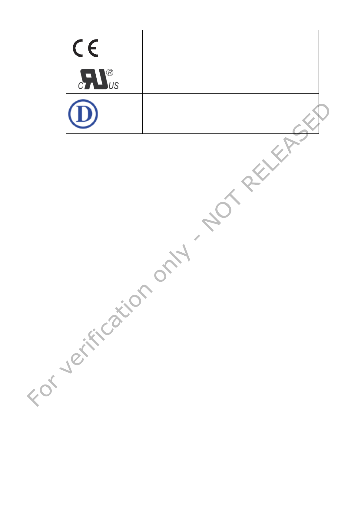
Table 3 – Symbols used in the Product label
Conformitè Europène
Compliance with Underwriters Laboratories
Compliance with Demko IEC/EN 60601
VERIFICATION ONLY 11 NOT RELEASED
Page 12

1.9 Biological Hazard and Returns
The structure and the specifications of this device as well as the materials used for
manufacturing makes it easy to wipe and clean and therefore suitable to be used for
various applications in hospitals and other medical environments, where procedures for
frequent cleaning are specified.
However, normal use shall exclude biological contaminated environments, to prevent
spreading of infections.
Therefore use of this device in such environmen t s is at the exclusive risk of C u stomer.
In case this device is used where pote ntial biological contamination cannot be excluded,
Customer shall implement the decontamination process as defined in the latest edition of
the ANSI/AAMI ST35 standard on each single failed Product that is returned for servicing,
repair, reworking or failure investigation to Seller (or to the Authorized Service Provider) .
At least one adhesive yellow label shall be attached on the top site of the package of
returned Product and accompanied by a declaration statement proving the Product has
been successfully decontaminated.
Returned Products that are not provided with such external deco ntamination label, and/or
whenever such declaration is missing, can be rejected by Seller (or by the Authorized
Service Provider) and shipped back at Customer expenses.
VERIFICATION ONLY 12 NOT RELEASED
Page 13
2 The FCP-NGP1 Computing Platfor m
2.1 Introduction
The FCP-NGP1 is a component of the Medtronic Care Link Encore Programmer 29901. T his
latter system is a implantable medical device programmer use d to communicate with an
implantable cardiac pacemaker or an implantable cardio-verter defibrillator.
The Medtronic System Care Link Encore Programmer 29901 shall be battery power ed or
line powered by a medical external PSU. The MPI includes the device telemetry provi ding
two-way communication with an implantable cardio-verter-defibrillator (ICD) or cardiac
pacemaker and ECG.
Computing Platform FCP-NGP1 is designed, certified and produced by FIMI. Care Link
Encore Programmer 29901 is certified by M edtronic and produced by P lexus. The external
PSU is produced and certified by APS (Mod. APS100EM-190530). The custom battery
FBT3S2P is certified and produced by STL - Pegatron Corp .
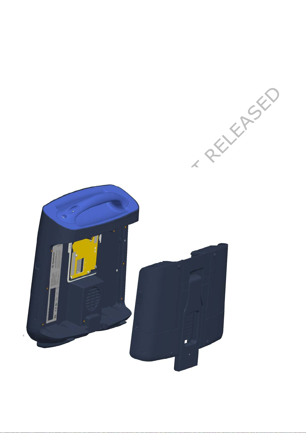
Below the illustration of how the FCP-NGP1 mates with MPI part that carries a foldable
kickstand.
VERIFICATION ONLY 13 NOT RELEASED
Page 14
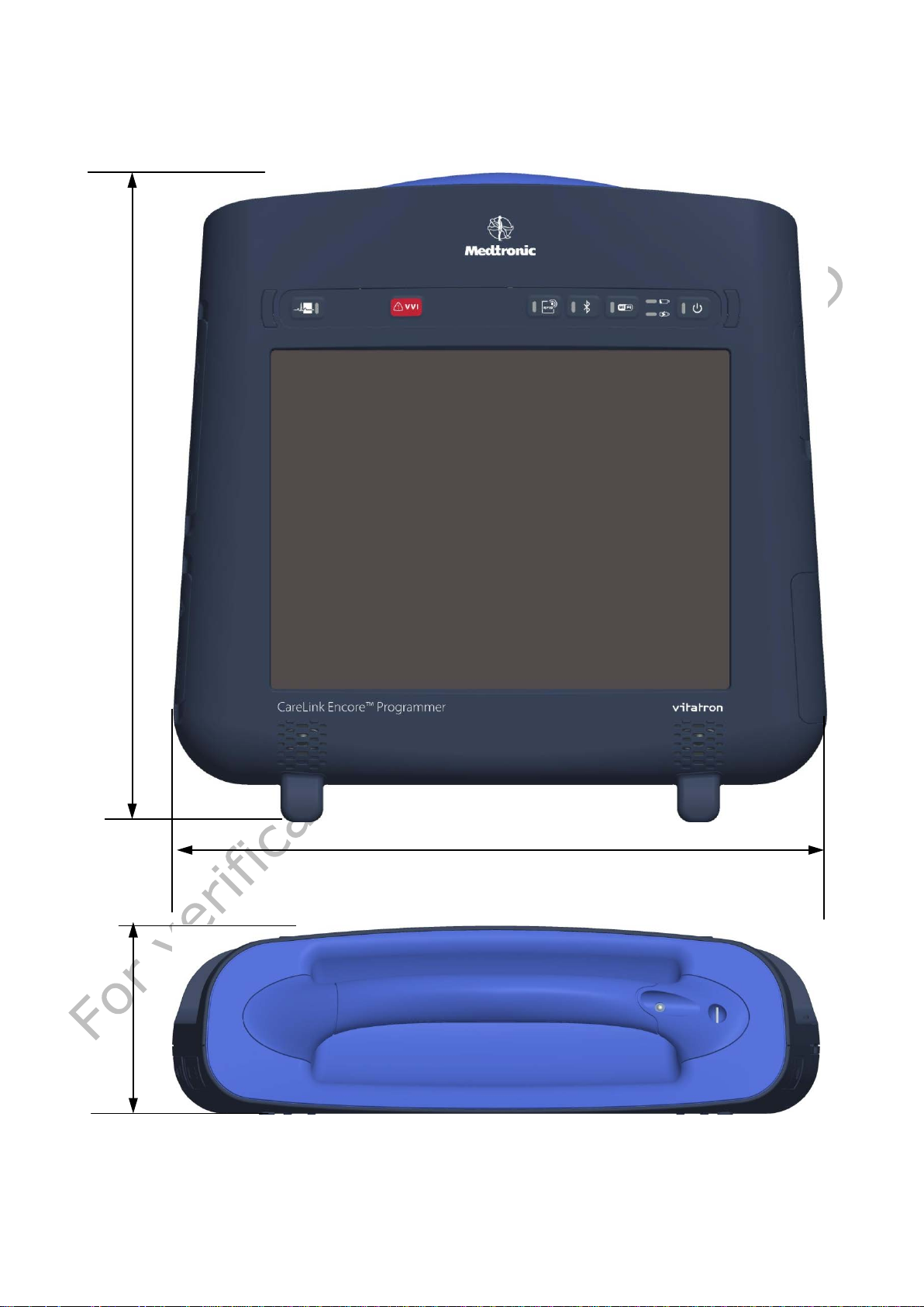
2.2 Overview
353
102 357.5
2.2.1 Dimensions (in mm)
VERIFICATION ONLY 14 NOT RELEASED
Page 15
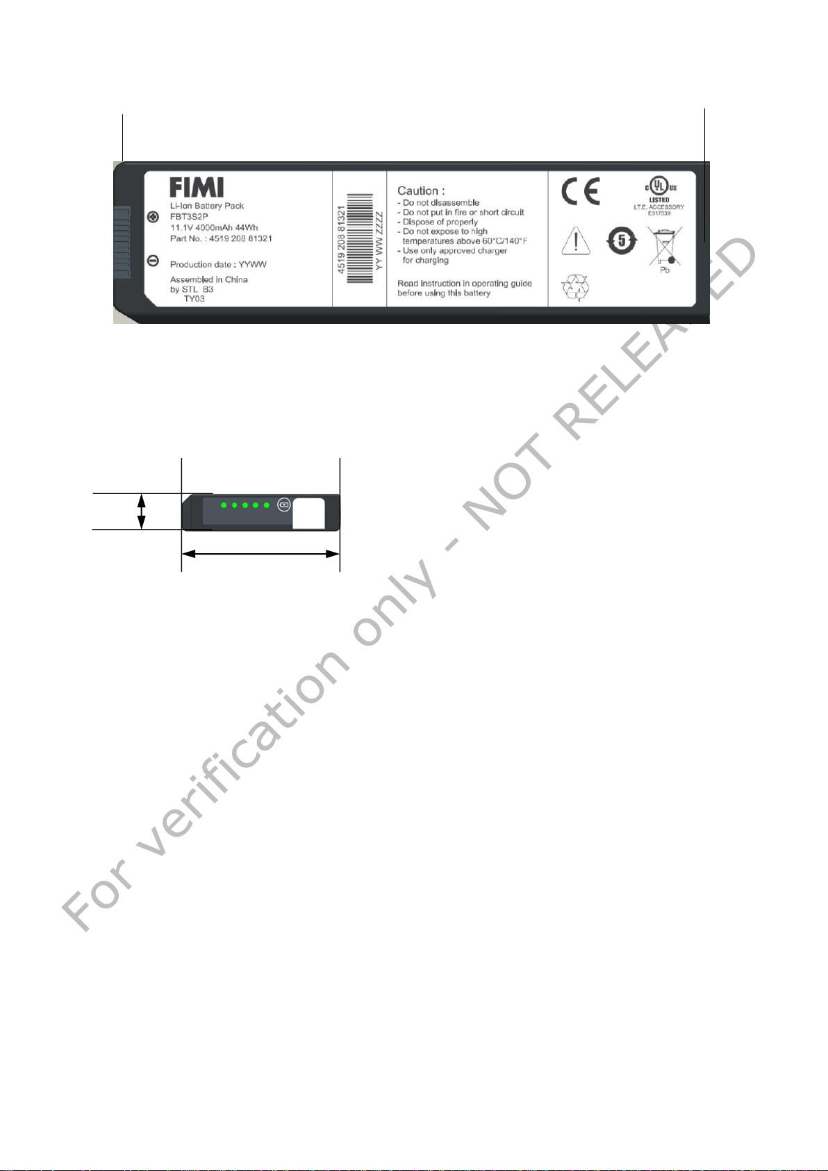
2.2.2 Battery dimensions (in mm)
215.5
13.7
2.2.3 Weight
Your NGP1 Computing P latform has a total weight
of 3.6 Kg with battery and stylus pen inserted
VERIFICATION ONLY 15 NOT RELEASED
Page 16
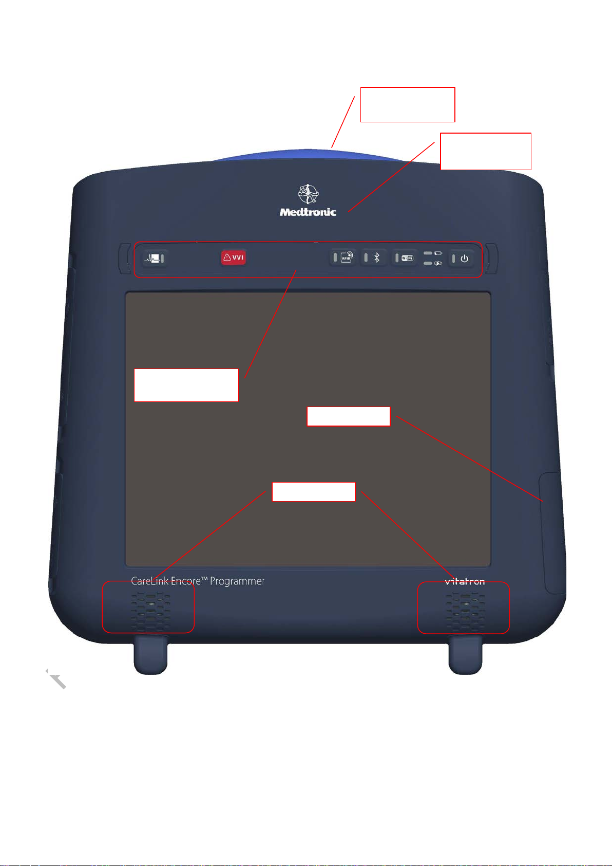
Loudspeaker
RF-ID
Battery door
Front Keyboard
and indicators
2.2.4 Features and connectivity
The below figures show the key features of The NGP Computing Platform
Transportation
handle
detection area
VERIFICATION ONLY 16 NOT RELEASED
Page 17
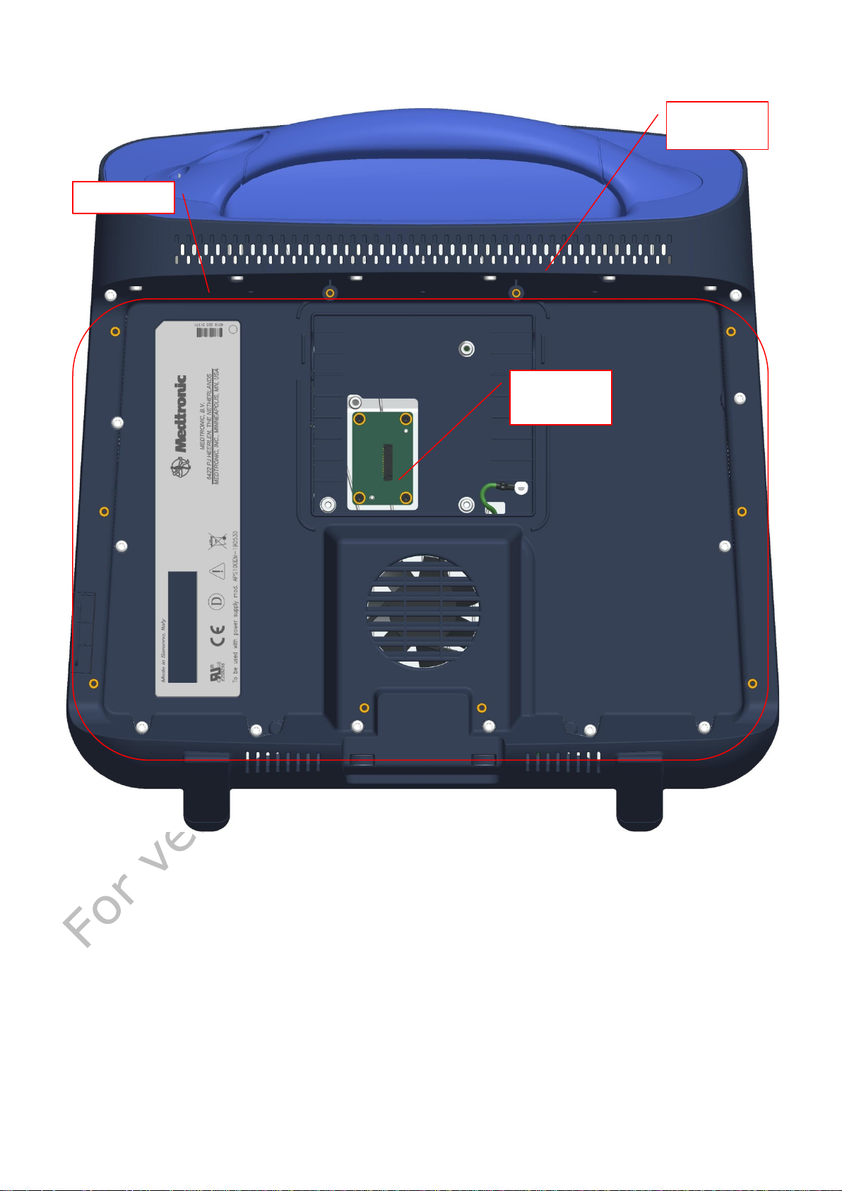
MPI Bay
Ventilation
slots
MPI
connector
VERIFICATION ONLY 17 NOT RELEASED
Page 18
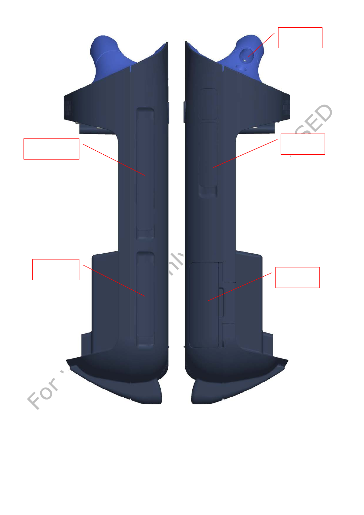
Express
Battery
DC jack and
VGA and USB
Pen
receptacle
ports doors
LAN door
card door
door
VERIFICATION ONLY 18 NOT RELEASED
Page 19
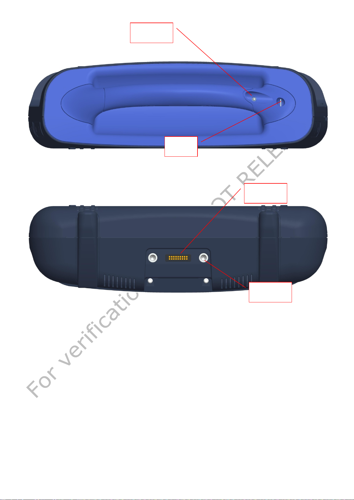
Pen
Docking
Docking
receptacle
Tether
hook
connector
pins
VERIFICATION ONLY 19 NOT RELEASED
Page 20
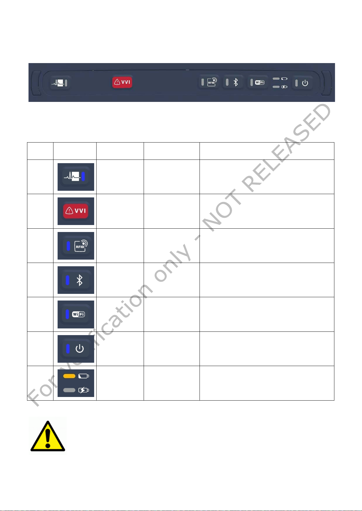
1 Blue
Waveform viewer
Application dependent – See Medtronic
2 Blue
Emergency hot
3 Blue
RFID enable
By touching it, the RFID scan is activated (if
RFID functionality is enabled in the BIOS
hen the RFID is
Blue
Bluetooth Enable
By touching it, the Bluetooth connectivity is
enabled or disabled (if Bluetooth functionality
The Blue LED is ON when the Bluetooth is
Blue
Wi-Fi Enable
By touching it, the Wi-Fi connectivity is
Fi functionality is
Fi is
when the Computing
Upper: yellow
Lower: yellow
Battery status
Upper LED : Indicates the battery s ta tus
diations that can be magnified by the
DO NOT VIEW LEDS DIRECTLY WITH
2.2.5 Buttons, indicators,
The NGP1 Computing platform has several buttons and indicators, all grouped on a
membrane keyboard located on the top of the front part.
The buttons and the indicators can be operated both in FW and SW mode. While the
installed application manages the SW mode ( not covere d in this manual) here below you
can find a description of the buttons and indicators while in the FW mode.
Symbol LED color Function Description
Carelink Encore Programmer User Manual
key
setup)..
The Blue LED is ON w
scanning
is enabled in the BIOS setup). .
enabled.
enabled or disabled (if Wienabled in the BIOS setup).
The Blue LED is ON when the Wienabled.
Blue Power On button Power On / stand-by button.
The Blue LED is ON
platform is ON
indicators
/ green
The Blue LED blinks when the Computing
platform is OFF bu t c onnected to the mains.
Lower LED : indicates the battery charge. See
3.1.4
Table 4 – Button primary FW functionality description
Warning: Led can generated ra
improper use of optical devices.
OPTICAL INSTRUMENTS CLASS 1M LED PRODUCT
VERIFICATION ONLY 20 NOT RELEASED
Page 21
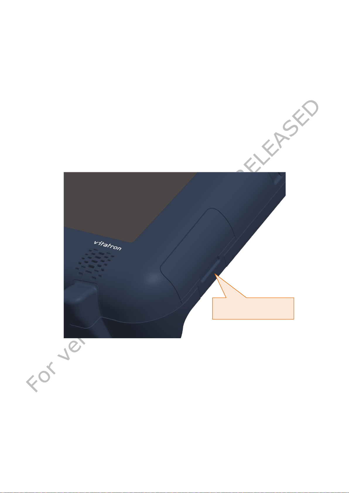
Lift the door up by pressing
recess
3 Getting started
3.1 Pre requisites
The NGP1 Computing Platform is a component (or subsystem) of Medtronic Carelink
Encore Programmer and other subsystems are the Medtro nic Patience Interface( MPI) and
associated Firmware, cables and software.
The operation of the computing platform is then depending on the loaded OS and
applications. So the following user information are covering o nly functionalities that are
minimally depending on the final use and configuration.
3.1.1 Insert the battery
The NGP1 Computing Platform includes a high capacity Lithium-ion battery that fits into
the right side of the unit Under normal conditions, you can run the NGP1 Computing
Platform on battery power for about two and a half hours. Keep the battery in an ambient
temperature of l es s tha n 40°C (104°F).
The battery, removed from its envelope, can be inserted as follows
Open the door with an upwards movement , being sure that the NGP1 Computing Platform
is in a stable position or it is held firmly. Then fully rotate clockwise the door. The battery
is anyhow kept in position by a hook located on the lower si d e of th e door opening.
Push the hook downwards until the battery is released and slightly ejected by the spring
loading mechanism.
VERIFICATION ONLY 21 NOT RELEASED
upward on the battery door
Page 22
clockwise the door
Push the white hook fully
After hearing a click and with
the door fully pulled up rotate
downwards till the battery
pack is released
VERIFICATION ONLY 22 NOT RELEASED
Page 23
Note: Under normal conditions, you can run the NGP1 Computing
But the
the selected
Operative System
Battery removal slip
In the very unlikely event of a battery pack blocked in its compartment (due to shocks or
other abnormal usage conditions) While keeping the hook fully downwards, the removal
slip can be used to pull out the pack.
The battery pack can be reinserted by reversing the process.
Warning: To avoid personal injury, handle the battery with care. Do not
open, puncture, short, or expose it to fire or water
Warning: The IP 21 performance requires that the battery do or is fully
closed and latched.
Platform on battery power for about two and a half hours.
operation on battery can be increased if th e NGP1 Computing Platform is
set with the proper Power Management settings under
VERIFICATION ONLY 23 NOT RELEASED
Page 24
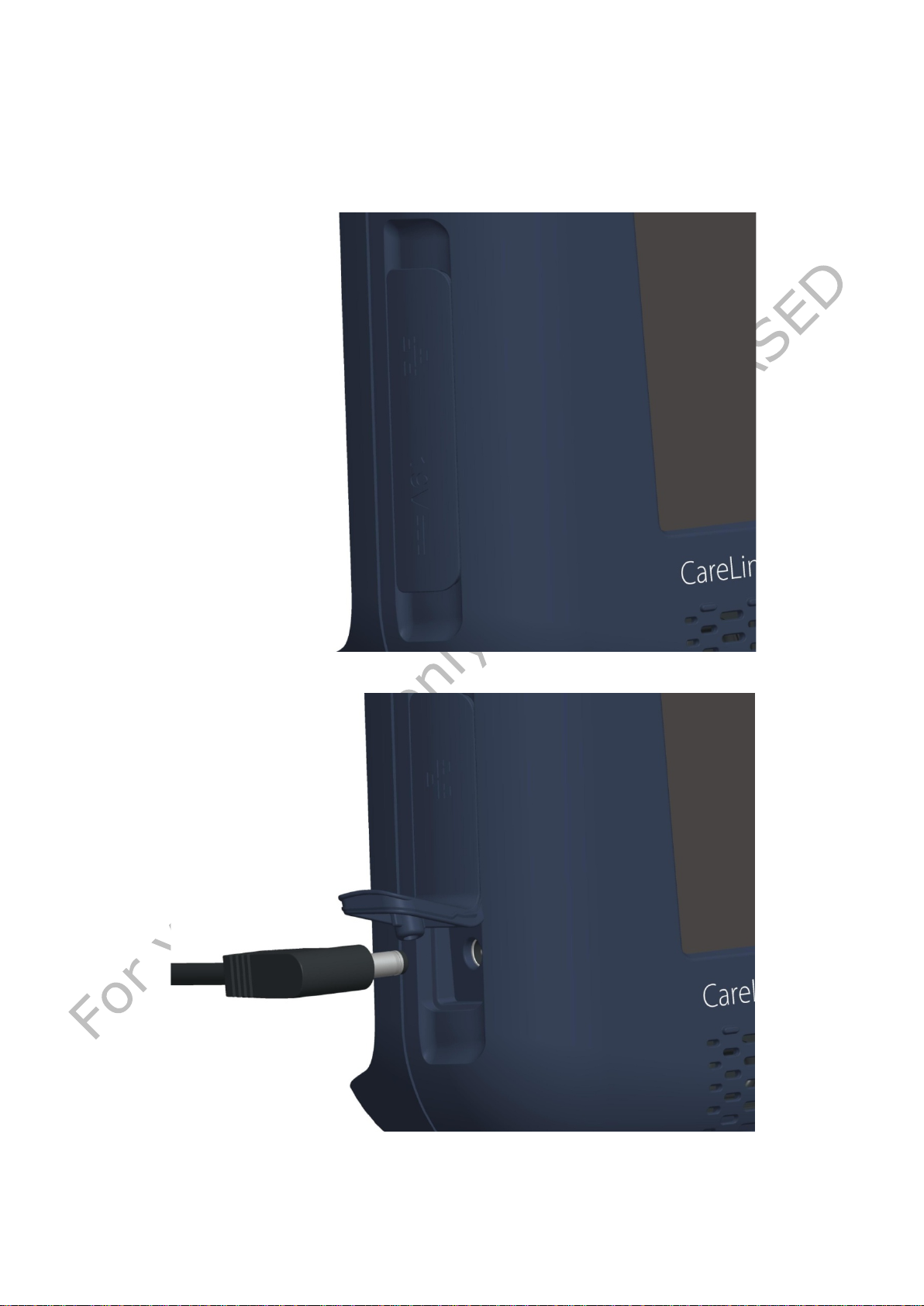
3.1.2 Connect the AC adapter
As the battery is delivered with around 50% of the charge, it is recommende d to charge it
fully for the first time. The battery is charged by connecting the NGP1 Computing Platform
to its AC adapter as il lustrated below. The D C plug must be connected by lifting the lower
part of the rubber door placed on the bottom left part of the NGP1 Computing Platform.
VERIFICATION ONLY 24 NOT RELEASED
Page 25
Note: When there is the AC adapter inserted, the NGP1 Computing
, when using the NGP1 Computing Platform
or when the NGP1
Note: When the AC adapter is
the Power LED on the keyboards
0.5 Hz in
order to indicate the existing
The AC adapter allows to power the Comp uting Platform and to charge the battery pack, if
present.
Platform is los in g its IP21 grade.
It is then recommended
disconnected from the AC adapter, to carefully close the rubber door. The
AC adapter must not be used in wet environments
Computing Platform is cleaned with liquids.
inserted and connected to the mains
while the Computing platform is off ,
blinks at a rate of 0.4 –
connections to the mains.
For additional information about the NGP1 Computing Platform AC adapter, please consult
paragraph 5.11.
3.1.3 Turning the system on
The NGP1 Computing Platform can be turned on by pressing
the Power ON / stand by button.
After one second the LED turns ON. For a complete
indication about this LED signalling, see below.
The system starts booting.
VERIFICATION ONLY 25 NOT RELEASED
Page 26
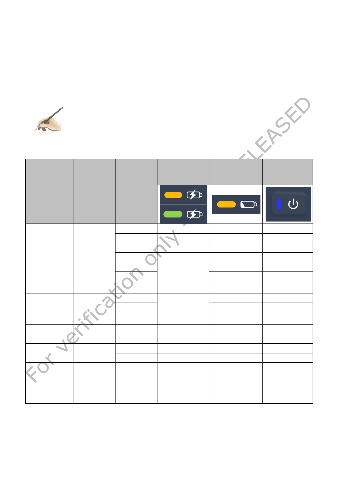
Note To maximize the performance and the life of your battery, it is worth
battery charge is less than 10%.
Battery charge
status
Power ON
Fully charged
Charged /
Charging /
Green
( if more than
fully
Charging /
Amber
has
less than 90%
charge)
Discharging /
Discharging /
Battery pack
(NGP
connected to
AC Adapter)
3.1.4 Charging the battery
When the NGP1 Computing Platform is connected to AC power (or docked into its docking
station), the battery automatically charges until it reaches a full charge. This happens in
any power state of the NGP1 Computing Platform, either when the unit is hibernated or
fully operating or OFF.
Typically an empty battery can be fully charged in less than two hours.
There are two LEDs (one bicolour) that are indicating the status of the battery and the
status of its charge process, when active. The indication varies also depending on the
operating condition (power state) of t h e NGP1 Computing Platform.
to deplete the battery charge to less than 10% every two weeks.
To deplete the battery, use your NGP1 Computing Platform on battery
power only until you hear a notification from the Operative system that the
The below table indicates the three LED behaviour (Battery LEDs and Power LED).
Battery
Battery
status
AC Adapter
LED
Computing
platform
status
LED
LED
/ Not critical
Not critical
Not critical
Critical
Critical
Very critical
not present
Connected
Not
connected
Connected
Connected
Not
connected
Not
connected
Connected
OFF ON OFF Blink
ON ON OFF ON
OFF OFF OFF OFF
ON OFF OFF ON
OFF
ON OFF ON
90% till
OFF Blink
charged)
OFF
OFF Blink
(if battery
ON OFF ON
OFF OFF OFF OFF
ON OFF ON ON
OFF OFF OFF OFF
ON OFF Blink ON
OFF OFF OFF Blink
ON OFF OFF ON
Table 5 - Status and battery conditions vs. NGP1 Computing Platform status
VERIFICATION ONLY 26 NOT RELEASED
Page 27
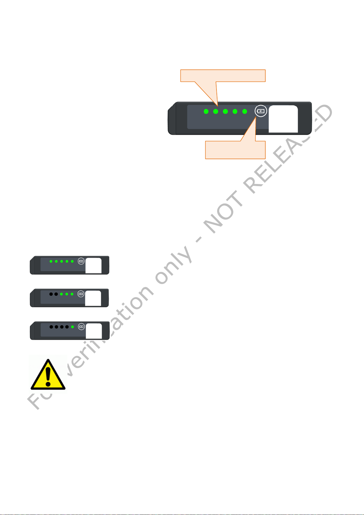
In case the application SW does not give you a status log about the
n SW does not give you indication about the need to
if the battery
0% of the original run time and/or the
battery charge time increases significantly.
Besides any indication given by the
keyboard LEDs on the battery
ck itself can
tions to the user
In fact , by pressing the button on
the front side of the pack for less
LEDs are
lighted on displaying the “relative
First four LEDs represent a
Battery charge / life
3.1.5 Battery pack indicators
charge, the battery pa
give some indica
about life and charge
than two seconds, the 5
State of Charge”with these criteria:
20% of the total charge.
The fifth LED represent a
minimum 15% of the charge.
This means that all the 5 LEDs on are ind icating a charge of mor e than 9 5%, wh ile, e.g. 2
LEDs on represent a charge state of more than 40% , but less than 60%.
If the button is pressed instead for more than 2 seconds then the LED indicator displays
the indication of how the full charge capacity has degraded with respect to the original
design capacity, after a give life or number of charge cycles.
The indication is according the below table:
Dual function LED indicators
monitor button
100 % - 80 % Full charge capacity / Design capacity – LED
battery pack health, it is advisable to per iodically check about the health
status of your battery with the built-in indicator.
In case the applicatio
replace the battery pack, please consider its replacement
run time drops below about 6
1 – 5 blink five seconds at 2 Hz frequency
79 % - 60 % Full charge capacity / Design capacity
LED 1 – 3 blink five seconds at 2 Hz frequency
Less than 60 % Full charge capacity / Design capacity –
LED 1 blinks five seconds at 2 Hz frequency
VERIFICATION ONLY 27 NOT RELEASED
Page 28

nd the metal parts of the
When there is an external peripheral connected, the NGP1 Computing
When connecting external equipments to any door , follow the IEC 60601-
4 Using your NGP1 Computing Platform
4.1 Booting the system
When the system starts up, the selected splash screen is displayed and prior to that,
indications o f BIOS an d FW versions area shown on the to p r ight c o rner. The CMOS menu
setup is locked and allowed only to service personnel.
4.2 Connecting external peripherals
The computing platform is offering a large deal of connectivity through a series of
interfaces that are compliant with the most popular IT standards.
All the connectors are placed on the sides of the Computing platform and are hidden and
sealed by silicon rubber door, that are guar ante e ing the IP2 1 pr o perty o f the de vice whe n
closed.
A series of precautions are needed when connecting external devices .
The operator shall avoid to touch the patient a
interface ports simultaneously
Platform should not be used in wet environments or cleaned with liquids.
1-1 requirements in order to guarantee patient or bystander safety.
If not aware of the requirement, verify the current leakages
VERIFICATION ONLY 28 NOT RELEASED
Page 29
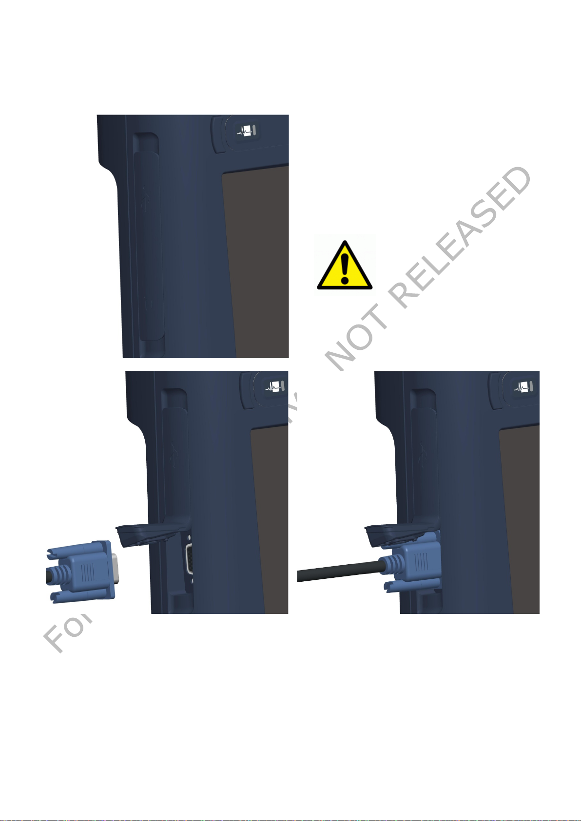
This VGA output is permanently enabled
in clone mode, so the output format is
16 million
Warning: The IP 21
performance requires
door is fully
external monitor
losing its IP21 grade.
4.2.1 External Monitor Connection
On the left side of the Co mputing platform , under the spec ifically designated rubber door,
there is a D-sub connector meant for an analog video connection to an external VGA
monitor.
1024 x 768 dots @. 60 Hz –
colors
that the VGA
closed. When there is an
connected, the NGP1
Computing Platform is
VERIFICATION ONLY 29 NOT RELEASED
Page 30
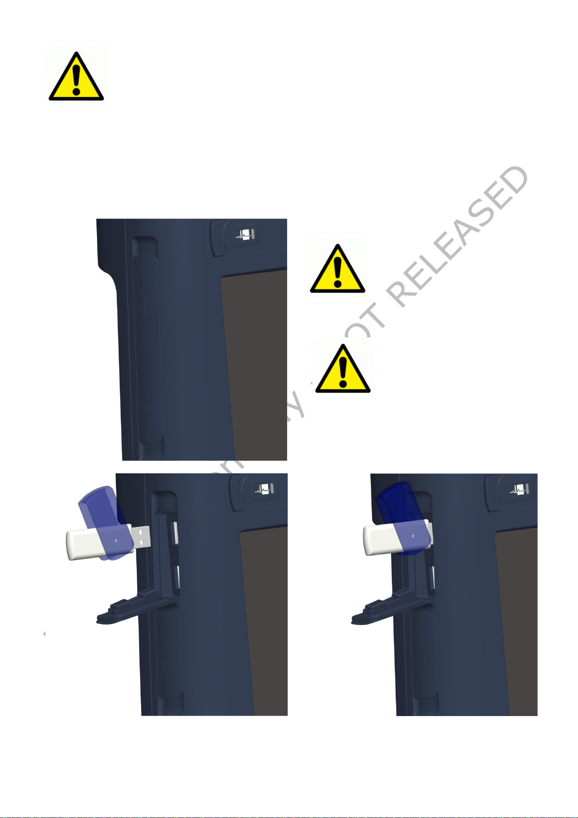
Even if the
ors are sufficiently
spaced and the connectors
strength is very robust, it
is advised to use extension
cables in case of bulky or
Warning: The IP 21
performance requires
that the Express Card
losing its IP21 grade.
When connecting external equipments to the VGA door , follow the IEC
in order to guarantee patient or bystander
60601-1-1 requirements
safety.
Verify the current leakages
4.2.2 USB doors
The NGP1 Computing Platform has two USB 2.0 standard Type A connection, located at its
left side, under the same rubber element that covers the VGA connector.
These USB connections can deliver power to the plugged device according to the USB
specifications: 0.5 Ampere max on a +5V supply line. A multiplicity of types of
peripherals are supported by the standard.
Warning:
do
heavy USB peripherals .
door is fully closed. When
there is an external USB
device inserted, the NGP1
Computing Platform is
VERIFICATION ONLY 30 NOT RELEASED
Page 31
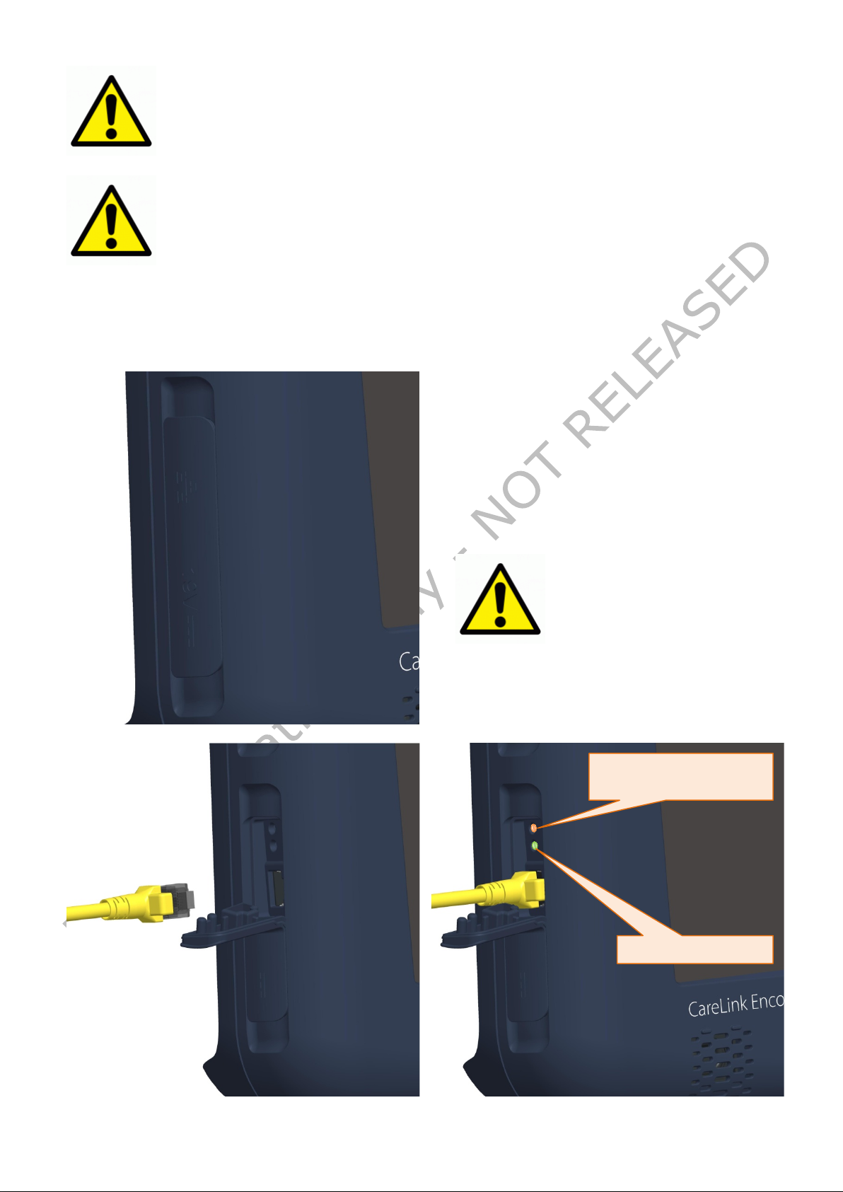
Under the same door also two LED
onnection (Green
Warning: The IP 21
performance requires
door is fully
losing its IP21 grade.
When connecting external equipments to the USB ports , follow the IEC
in order to guarantee patient or bystander
USB and VGA ports requires a check of the total patient leakage current
Green LED : Connected
Orange LED :
60601-1-1 requirements
safety.
Verify the current leakages
also using a device meeting the IEC 60601-1 requirements
4.2.3 Ethernet connection
On the top left side of the Co mputing platform , under the spe cifically designated rubbe r
door, there is 8 pin RJ45 LAN door (10/100 Mbit) that supports standard Ethernet cables.
indicators are provided. They are showing
the presence of a c
indicator) and the data transmission /
reception activities (Orange indicator blinking)
that the LAN
closed. When there is an
external cable, the NGP1
Computing Platform is
Transmitting / receiving
VERIFICATION ONLY 31 NOT RELEASED
Page 32
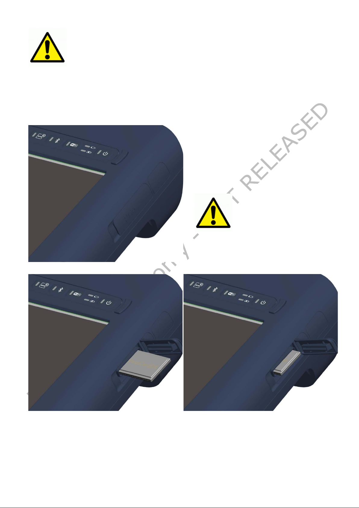
Several types of peripherals are
After opening the door, you need to
the slide in movement becomes
Warning: The IP 21
performance requires
that the Express Card
an external
ExpressCard34 based
When connecting external equipments to the LAN jack , follow the IEC
in order to guarantee patient or bystander
60601-1-1 requirements
safety.
Verify the current leakages
4.2.4 Express Card slot
On the top right side of the Co mputing platform , unde r the specifically designated rubbe r
door, there is a slot for Express Card 34 devices.
supported by the standard ( Phone cards,
Storage media, etc.).
gently insert the device till you feel that
contrasted and then reaches the end.
door is f ully c lose d. When
there is
device inserted, the NGP1
Computing Platform is
losing its IP21 grade.
VERIFICATION ONLY 32 NOT RELEASED
Page 33

5 NGP1 Computing Pla tfo r m features
5.1 Display
Your NGP1 Computing Platform has a sturdy 12.1" XGA TFT LCD display with the
following features:
• highly readable LCD (liquid crystal display) panel with a wide viewing angle
( typical +/-50°on both horizon tal and vertical directions).
• resolution of 1024 x 768 pixels
• Minimum output brightness ( with control set at 100%) of 400 cd/m2
• Long life LED backlight
5.2 Touch screen
Above the LCD display , a resistive touch screen panel allows both finger and passive
stylus pen input. High resolution and fast refresh rate are allowing precise and fast on
screen selection, dragging, scrolling.
Depending on the OS support or application, also right click features may be available.
The touch screen panel has a 4H hardness and it comes already fully calibrated. Due to
the specific 8 wire technology, long lasting precis ion is guaranteed and no use r calibration
is required.
The touch screen has an effective anti-glare and anti-reflection treatment acrylic screen,
with minimum impact on screen sharpness and light output.
5.3 Using your stylus pen
5.3.1 Pen characteristics
To be added
5.4 Using the RF-ID reader
The NGP1 Computing Platform has an integrated 13.56 MHz RF-ID (Radio Frequency
Identification) reader that you can use to retrieve information from RF-ID tags.
RF-ID technology makes use radio frequency (RF) transmissions to identify products or
persons. RF-ID does not require direct contact or line-of-sight scanning, and can be
scanned through many materials, including plastics, clothes, carton boxes etc., with the
exception of metal.
An RF-ID tag can store much more data than a typical bar code, and some RF-ID tags can
both transmit and record data. RF-ID can be used for asset tracking, identification,
process control, health care, and pharmaceutical applications.
The RF-ID reader supports the following formats ( proximity a nd vicinity ranges = 0 to 6
cm):
• ISO/IEC 15693
• ISO/IEC 18000-3
If supported by specific applications, the NGP1 Computing Platform allows you also to
write tags, provided that they are supporting the above standards. Using your RF-ID
reader is rather simple.
VERIFICATION ONLY 33 NOT RELEASED
Page 34
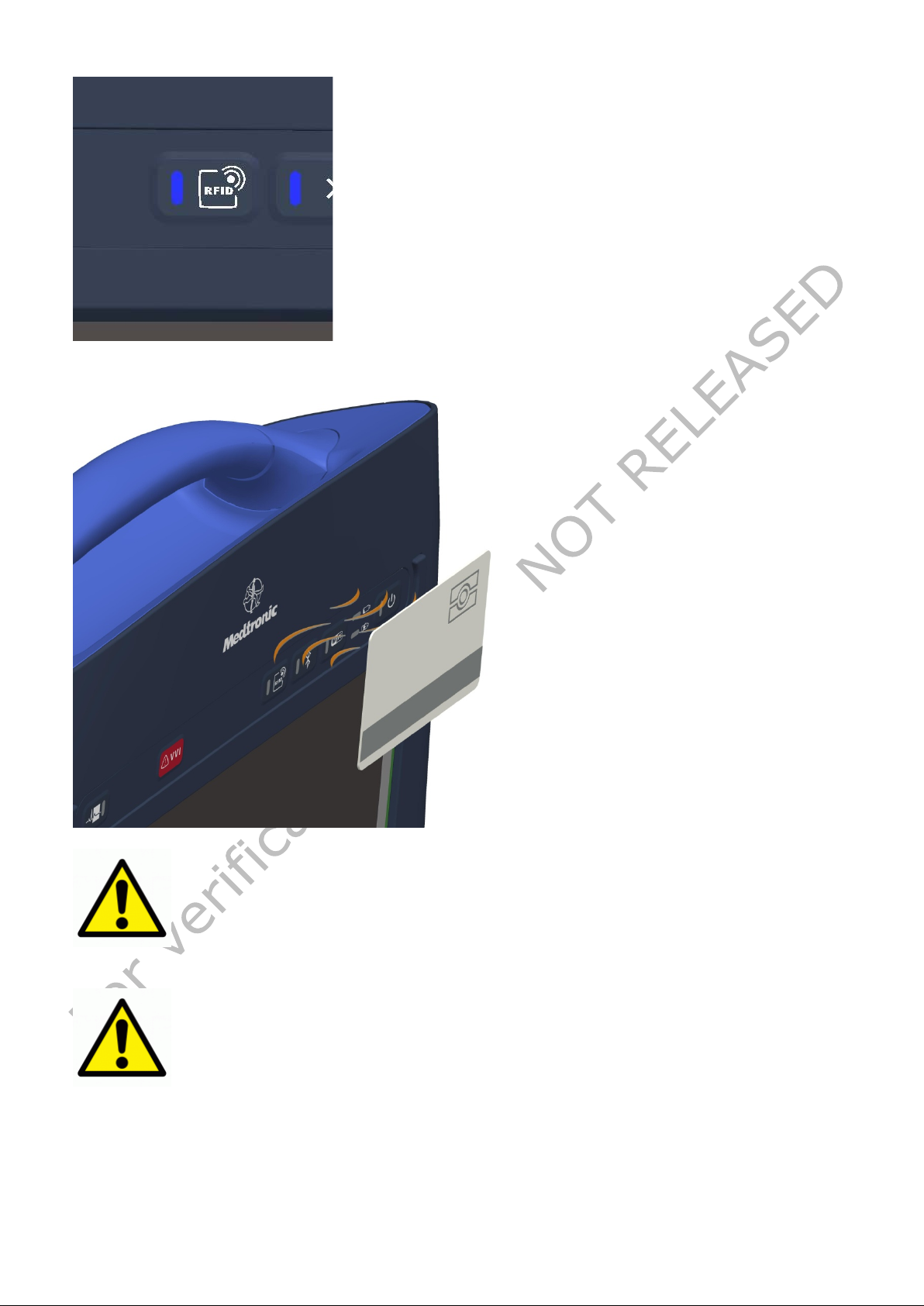
When the RF-ID button is pressed than the blue LED
you may have a
the LED
The use of wireless devices in medical environments may be restricted
about the policy that applies to the use of this device,
The use of the FCP - NGP1wireless devices during the pacemaker
programming phase must be evaluated and authorized by the final
ogrammer vendor, within their SW applications and within the
turns ON and the RF-ID section is energized. Depending
on the supporting SW application .
screen notification or hear also a start sound
Aim the RF-ID tag at the front of the unit, ensuring that
the tag is 2 to 4 cm from the RF-ID antenna scan area
(in case of large tags, having dimension of a credit card
size, the scanning distance can be up to 6-8 cm)
In case of a good read or at the end of t he scan time,
depending on the supporting SW application
turns off, there is a st o p so und and the tag contents are
displayed.
and must be evaluated and authorized by the Hospital authority. If you
are uncertain
please ask for authorization to use it prior to turning it on.
VERIFICATION ONLY 34 NOT RELEASED
Pr
prescribed operating instructions.
Page 35
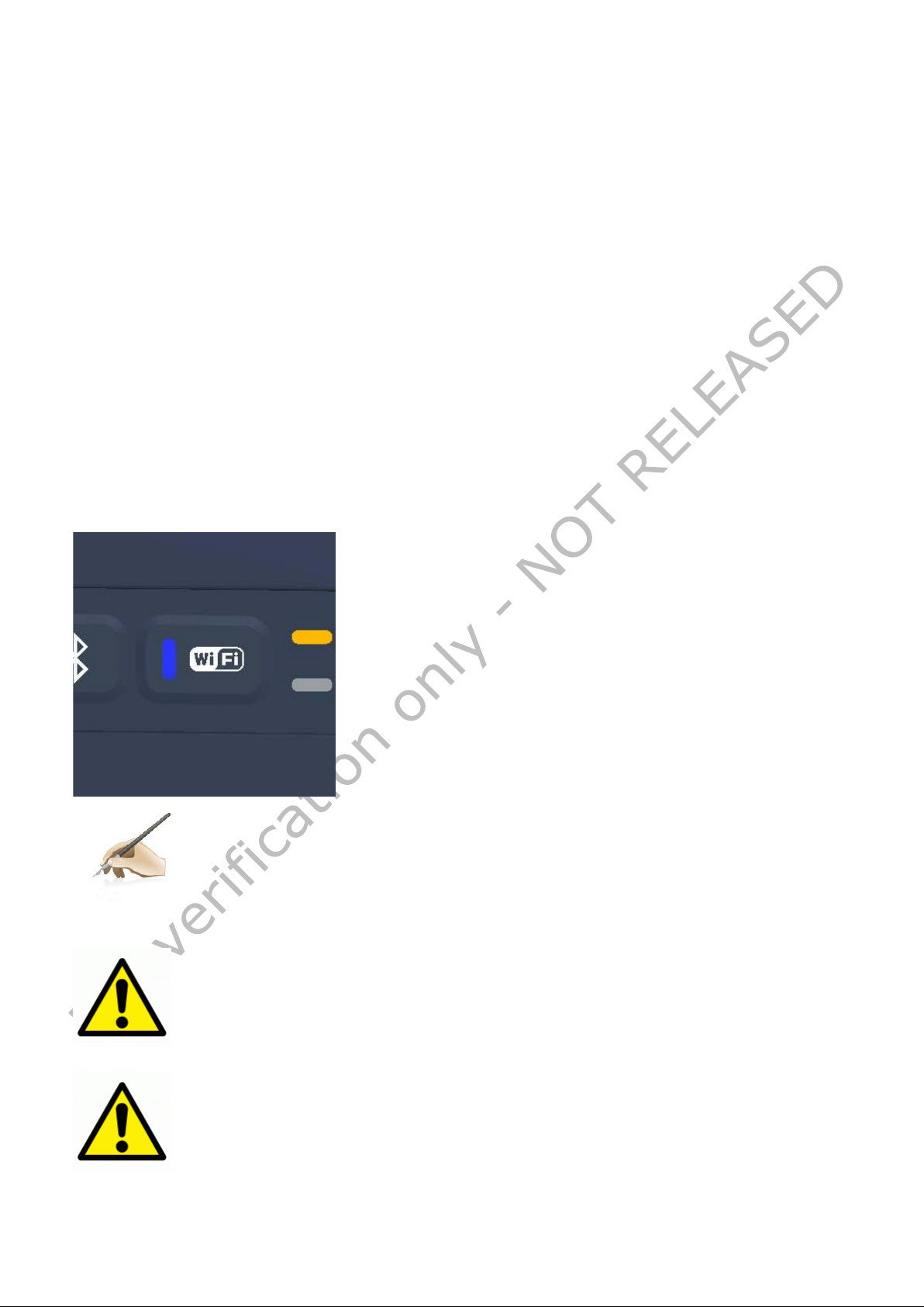
Besides a possible application software control, depending
Fi can be enabled or disabled via the button
and the corresponding LED will be
Note: The Wi-Fi control on the keyboard, if enabled, is a fast way for
adio emissions are
consume power. Then, in order to reduce
device, when not i n use.
The use of wireless devices in medical environments may be restricted
are uncertain about the policy that applies to the use of this device,
The use of the FCP - NGP1wireless devices during the pacemaker
programming phase must be evaluated and authorized by the final
Programmer vendor, within their SW applications and within the
5.5 Using the Wi-Fi (802-11 ABGN)
The NGP1 Computing Platform has an on-board 802.11a/b/g/n PCIe* Mini Card network
adapter that operates in both the 2.4 GHz and 5.0 GHz spectra.
The on board module is a highly integrated wireless local area network (WLAN) solution to
let users data content exchange through the latest wireless technology w ithout using the
extra cables and cords. It enables a h igh performance, co st effective, low power, co mpact
solution.
Compliant with the IEEE 802.11a/b/g/n standard, The module uses Direct Sequence
Spread Spectrum (DSSS), Orthogonal Frequency Division Multiplexing (OFDM), DBPSK,
DQPSK, CCK and QAM baseband modulation technologies.
A high level of integration and full implementation of power management functions
specified in the IEEE 802.11 standard minimize system power requirements
It features:
• IEEE 802.11a/b/g and n quad-mode
• Advanced security via 802.11i
• WEP 64-bit and 128-bit encryption
• WPA(Wi-Fi Protected Access)
• WPA2 with AES CCMP
on it, the Wilocated on the keyboard.
You have to touch the Wi-Fi button for enabling or disabling
the Wi-Fi functionality
turned on.
disabling it if you are entering in areas where the r
controlled or not allowed.
Furthermore wireless devices
power consumption and lengthen the battery life, disable the Wi-Fi module
and must be evaluated and authorized by the Hospital authority. If you
please ask for authorization to use it prior to turning it on.
VERIFICATION ONLY 35 NOT RELEASED
prescribed operating instructions.
Page 36
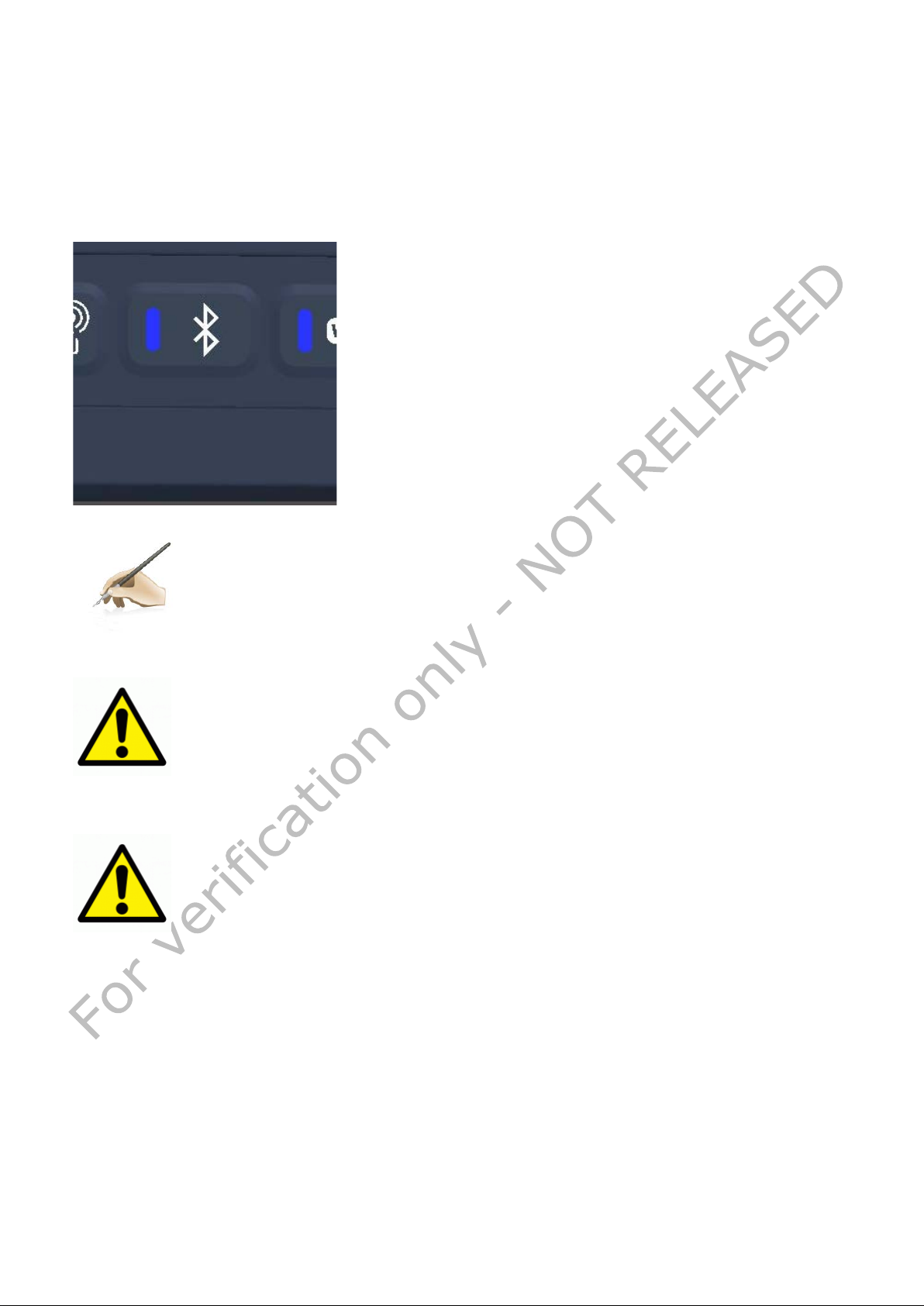
You have to touch the Bluetooth button for enabling or
, is this is not put
the corresponding LED
Note: The Bluetooth control on the keyboard, if ena bled, is a fast way for
disabling it if you are entering in areas where the radio emissions are
Furthermore wireless device consume power. Then, in order to reduce
he battery life, disable the Bluetooth
device, when not i n use.
The use of wireless devices in medical environments may be restricted
the use of this device,
The use of the FCP - NGP1wireless devices during the pacemaker
programming phase must be evaluated and authorized by the final
applications and within the
5.6 Using the Bluetooth
The NGP1 Computing Platform delivers a built in Bluetooth module designed according the
Bluetooth wireless technology 2.1 specifications, and including AFH (advanced frequency
hopping), EDR (enhanced data rate) functions, "HID Proxy" boot-time keyboard support
mode (if enabled) and other capabilities.
disabling the Bluetooth functionality
under control of a SW applicat ion.
will be turned on..
controlled or not allowed.
power consumption and lengthen t
and must be evaluated and authorized by the Hospital authority. If you
are uncertain about the policy that applies to
please ask for authorization to use it prior to turning it on.
Programmer vendor, within their SW
prescribed operating instructions.
VERIFICATION ONLY 36 NOT RELEASED
Page 37
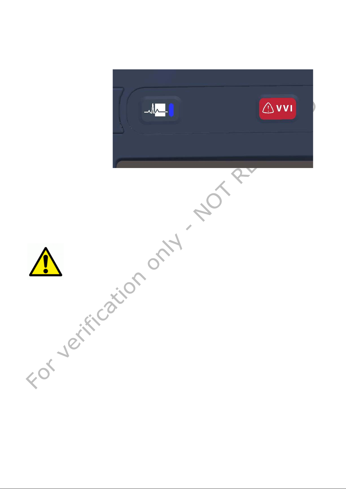
These two buttons are
under direct control of
the Customer SW
application and /or are
Keep the volume at the lowest level possible for a comfortable hearing.
Avoid noisy environments where you may be inclined to turn up the
become accustomed to the sound level, which may result in permanent
5.7 Using the Waveform Viewer (WFV) button and the Emergency
Hot Key (EHK)
directly managed by the
piggy-bagged MPI HW.
5.8 Audio solution
The NGP1 Computing Platform has a built-in high definition audio solution.
The system uses a couple of 2Watt speakers with a IP65 grade.
There is no embedded microphone or microphone input on the NGP1 Computing Platform.
It is recommended to use a cordless Bluetooth headset to enable voice processing
applications such as telephony, voice dictation or speech recognition.
volume.
Avoid long, continuous exposure to maximum sound pressure level as this
could impair your ability to hear other sounds. Furthermore your ears may
damage to your hearing without any noticeable discomfort.
Mute the audio if the prolonged hearing is causing discomfort
VERIFICATION ONLY 37 NOT RELEASED
Page 38
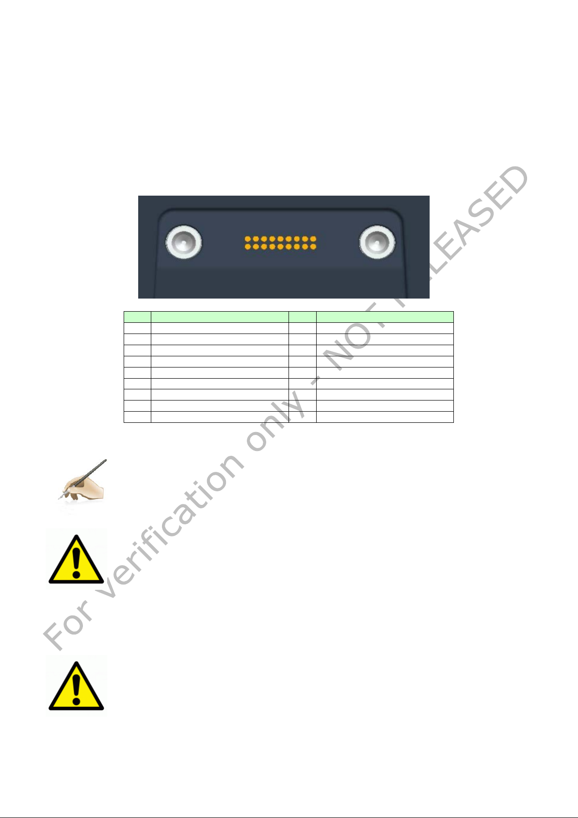
Pin
Signal
Pin
Signal
1
GND
10
DC - VCC
2
GND
11
DC - VCC
3
USBP3-
12
DC - VCC
4
USBP3+
13
Not Connected
5
Not Connected
14
PDL_Dock
6
Detect#_Dock
15
USBP4+
7
SUSC
16
USBP4-
8
SUSB
17
GND
9
DC - VCC
18
GND
Note: the docking connector is “enabled” only when the NGP1 Co mputing
As the mating of the NGP1 Computing Platform and its docking station
connectors needs to be very accurate, please, be sure that the NGP1
battery LED indicators that starts indicating that the NGP1
and icon shown in the icon
tray (if enabled on the used OS)
The NGP1 Computing Platform must be used in conjunction only with its
1 2 17
18
5.9 Docking connector
Even though the NGP1 Computing Platform has no docking station planned at the
moment, it offers docking provisions. In fact a docking connector is present on the
bottom of the NGP1 computing platform , sided by two metal docking / ground pins.
The NGP1 Computing Platform can be docked on its docking unit without any locking
mechanism. This allows a “grab and go” one hand removal when you have to take the
NGP1 Computing Platform seated in the docking station (please refers to the future
Docking station manual).
When the unit is docked all the funct ionalities of the system are anyhow available. Here
below the connector pi n-ou t for future references.
Table 6 - Connector l ayout specifications
Platform is fully docked. There are no voltages present on the connector
when the NGP1 Computing Platform is undocked.
Computing Platform is fully seated in its prescribed position, including:
change of the screen brightness
Computing Platform battery is charging
USB connection plug and play “sound”
future docking station. Do not attempt to connect or manipulate the
connections of the docking connector as this may resu lts in risks for the
user, bystander or patient
VERIFICATION ONLY 38 NOT RELEASED
Page 39

Use only the APS 100EM- 190530 AC adapter and power cord delivered
Note: The AC adapter supplied with the NGP1 Computing Platfo rm has no
form is
active, even with the NGP1 Computing Platform off.
5.10 _________________________________________________________
Security
5.10.1 Built-in features
Your NGP1 Computing Platform includes several features that are dedicated to increase
the level of security of your data. Among them:
• BIOS is accessible only by authorized personnel
• TPM (Trusted Platform Module) 1.2.
The Trusted Platform Module (TPM) is a specific protection against malware intelligent
attacks.
The nature of this security chip ensures that the information like keys, password and
digital certificates stored within is made more secure from external software attacks and
physical theft . W ith the handful of keys it stores, all cryptographic functions are performed
on the chip.
TPM provides the ability for a computing system to run app lications more secured, allows
secured remote access, performed electronic trans actions and co mmunication more safely.
These features are available but not activated in your NGP1 Computing Platform. T hey are
usually set up by your system administrators.
5.11 _________________________________________________________
Power adapter
Your NGP1 Computing Platform is delivered with a full range, IEC 60601-1 medical
approved, 100W full range (100-240V @ 50-60 Hz) AC power adapter APS 100EM190530 . This adapter is meant for safely supplying the most power demanding NGP1
Computing Platform configuration.
In fact the adapter can be used a lso for powering the NGP1 Computing Platform docking
station with the following configuration:
- NGP1 Computing Platform docked and fully ON
- NGP1 Computing Platform battery charger loaded and active
- docking station(refer to 5.9) battery charger loaded and active
- USB doors (NGP1 Computing Platform + docking station) loaded with Bus powered
devices
- LAN (on docking station) connected and active
Power-on LED indication.
But, as also shown in “Table 5 - Status and battery conditions vs. NGP1
Computing Platform status
connected to the AC adapter, there will be always a battery or Power LED
In case of incorrect use, the AC adapter, as well as the NGP1 C omputing Platform and its
docking station, have power limiting, over-current and short circuits protection.
Nonetheless, we rec ommend to follow the b elow warnings
“, once the NGP1 Computing Plat
with the NGP1 Computing P latform or its acces sories. Use of another type
of AC adapter or power cord may risk fire or explosion.
VERIFICATION ONLY 39 NOT RELEASED
Your NGP1 Computing Platform will be shipped with the right power cord
in use in all the countries. Power cord sets fo r use in other countries must
Page 40

meet the requirements of those countries.
Provide the right cord-set. In US and Canada “hospital grade” cord-set
has to be used, provided with instructions to indicate that grounding
rade. These
When in use, place the AC adapter in an open and ventilated area, such as
on a desktop or the floor (do not u se on w et surface). Do not cover the AC
Pay attention that the adapter cable and the power cord are routed far
Disconnect power cords and cables by grabbing the plug and not by
ble itself. As you pull out the connector, keep it evenly
If you use an extension cord with your AC adapter, ensure that the total
ampere rating of the products plugged into the extension cord does not
Anybody connecting additional equipment to medica l electrical equipment
he above mentioned
requirements. If in doubt, consult your local representative or the
protective earth conductor or the protective earthing system in the
reliability can be achieved only when the equipment is connected to an
equivalent receptacle marked hospital only or hospital g
instructions need to be marked either on the equipment or on a tag on the
power cord.
adapter with items that will reduce cooling.
from places where they can be tripped over or stepped on.
pulling on the ca
aligned to avoid bending any connector pins. Before you connect a cable,
make sure both connectors are correctly aligned.
exceed the ampere rating of the extension cable.
When using your power cord, make sure to position it around ob jec ts so it
will not be cut or punctured.
configures a medical system and is therefore re sponsible that the system
complies with the requirements for med ica l e lectr ica l s yste ms. Attention is
drawn to the fact that local laws take priority over t
technical service department
To avoid the risk of electric shock, this equipment must only be connected
to a supply mains with protective earth
The int ernal elec trical power source has to be used if the integrity of the
instal lation is in doubt.
5.12 _________________________________________________________
Battery
The NGP1 Computing Platform comes with a lithium ion rechargeable main battery having
a capacity of 4000mAh at an output vo ltage of 11.1 V (P/N 4519 208 81321). The first
instructions on how insert and charge the battery are given in section 3.1.1 The NGP1
Computing Platform has three battery indicators that show the charge/discharge status.
Refers to 3.1.5.
VERIFICATION ONLY 40 NOT RELEASED
Page 41
Note: The NGP1 Computing Platform OFF status is actually a minimum
it is possible that the completely charged battery can be found depleted.
adapter or with a charged battery pack
Note: A totally depleted battery will recharge with an initial peri od of pre-
This period may range
Replace the battery pack only with the replacement battery designed for
the NGP1 Computing Platform to avoid the risk of fire or explosion
cell battery packs) or battery packs with different
bly leading it to leak, overheat,
CAUTION:
to protect the battery from
ion batteries
ion batteries
Do not disassemble or modify the battery pack. If disassembled, the
Do not pierce the battery pack with a sharp object, strike it with a
circuiting can occur, possibly leading it to leak, overheat,
The battery pack enclosure should be checked upon collision damage;
If the battery pack leaks, gives off a bad odour, generates heat, becomes
discoloured or deformed, or in any way appears abnormal during use,
Do not transport the lithium ion batteries used in your NGP1 Computing
on baggage violates transportation law.
attery charger before
transporting it in carry-on or checked baggage
power quiescent state that anyhow draws energy from the battery. If the
NGP1 Computing Platform is left OFF on ba ttery for more than t wo weeks,
In this case the NGP1 Computing Platform must be turned ON with the AC
charge, during which the Windows Power Meter indicator of the remaining
battery charge (see
between 5 and 15 minutes.
resulting in personal injury.
Do not use the battery pack in combination with other types of battery
packs (such as drycapacities or brands. This can resu lt in it being over discharged during use
or overcharged during recharging, possi
emit smoke, burst and/or ignite.
3.1.4 ) will remain at 0%.
• Danger of explosion if battery is incorrectly replaced. Replace only with
the same or equivalent type recommended the manufacturer.
Li-ion batteries include special circuitry
damage due to overcharging or undercharging. As Lithiumalso require sophisticated chargers that can carefully mon itor the charge
process; put them in a charger not designed for Lithiumcreate a potentially dangerous situation.
• To charge the battery follow the instruction in this User’s Manual.
battery pack could leak, overheat, emit smoke, burst and/or ignite. Do not
connect the positive (+) and negative (-) terminals with a metal object
such as wire. Short-circuiting may occur leading the battery pack to leak,
overheat, emit smoke, burst and/or ignite.
hammer, step on it, or throw it. T hese actions could damage or deform it,
internal shortemit smoke, burst and/or ignite.
please refer to qualified service personnel.
recharging or storage, immediately remove it from the NGP1 Computing
Platform or charger and stop using it. If this is discovered whe n you first
use the battery, return it to your Supplier.
VERIFICATION ONLY 41 NOT RELEASED
Platform in checked baggage. You may take up to two spare batteries in
carryon luggage in addition to the one in your NGP1 Computing Platform.
Transporting batteries in checked baggage or transport ing more than two
spare batteries in carryRemember to remove battery packs from the b
Page 42
5.12.1 Storing main batteries
In case of long inactivity of the battery packs not inserted in the NGP1 Computing
Platform, it is preferable to store them neither fully charged nor totally empty. As the
battery will lose gradually its charge , it is recommended to recharge if the charge drops
below 20% or after a few months and possibly re-use it for a few recharge cycles.
5.12.2 Battery and energy management.
As already mentioned in paragraph 3.1.1, the battery charge can be wisely used and
extended by means of a few precautions. With a standard use, the typical battery life is
around two and half hours.
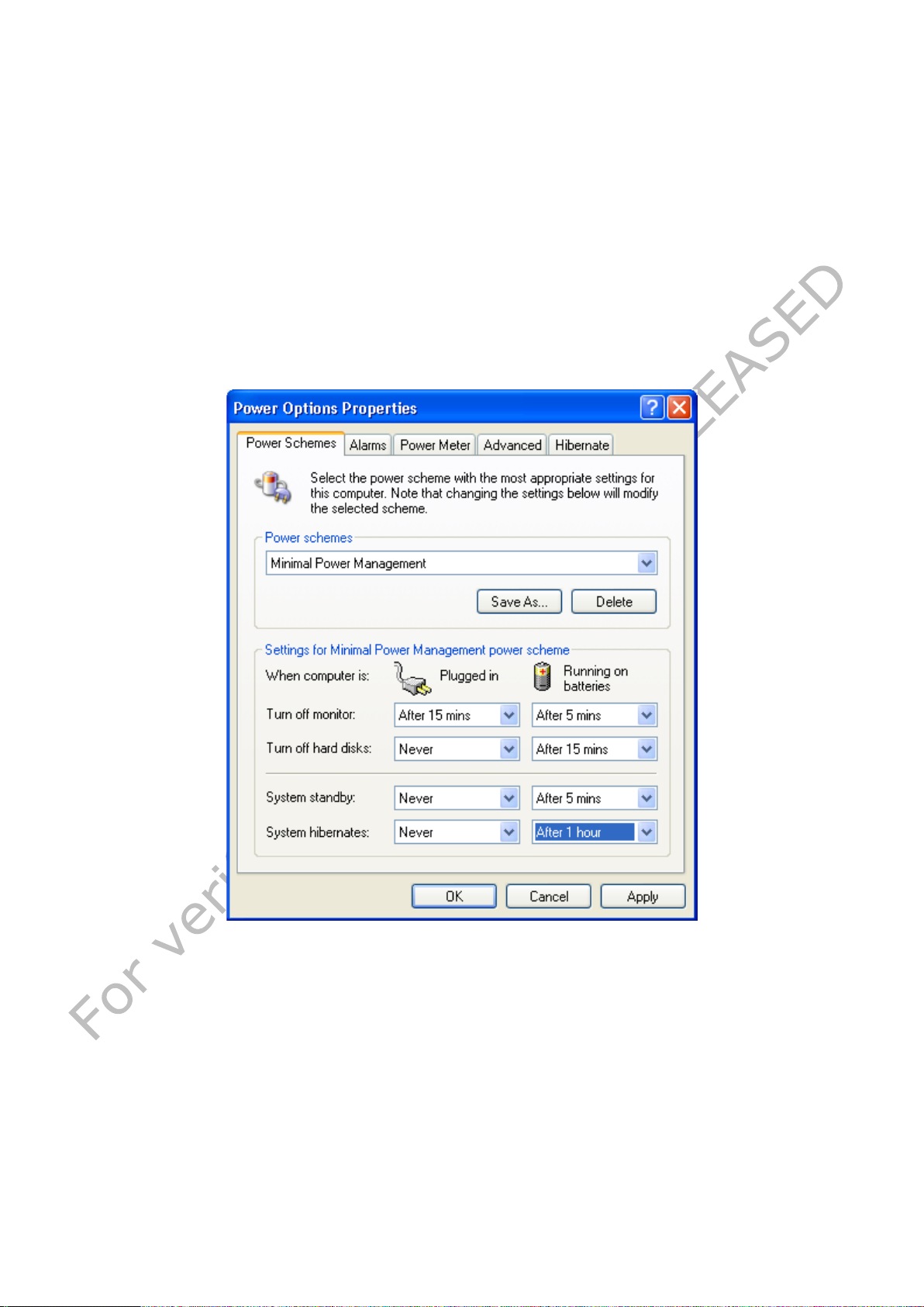
If a Windows OS is used, under Control panel / Power Options / Power schemes, you can
chose among Power management that matches the typical usage of the system while
maximizing the battery life and minimizing the waste of energy.
As example, turning off the display when the NGP1 Computing Platform is not used, can
help increasing the battery life of typically 10%.
Remember that the display, processor, wireless cards, and accessory drives all draw on
the battery, so adjust properties and disab le unused accessories while running on bat tery
power.
VERIFICATION ONLY 42 NOT RELEASED
Page 43
Liquids or fluids
Isopropanol 100% - CAS 67-630
Haemosol 1% in 1 litre water – 00-238-1
Chlorine 250 ppm in 1 litre distilled wa ter
Chlorehexidine 0,5% in 70% Ethanol – 00-125
Ethanol 70% - 70-CAS 64-17-5
Cidex- Phthalaldehyde solution – 00-237
Iodine 1% in 70% Ethanol – 06-318-1
Artificial sweat (5% KCL, pH=3) – 00-422-1
Hexabrix 320
Coffee with milk and sugar
Alcohol 95%
test due to Iodine, Haemosol and Hexabrix 320. Clean the product
s and
6 NGP1 Computing Pla tfo r m Maintenance
6.1 Cleaning
The NGP1 Computing Platform is designed for being subjected to periodic cleaning and
disinfection, as typical for infection control, in a healthcare environment, Materials and
shapes as such that the unit can be cleaned with sprays and liquids.
Recommended cleaning solutions have to follow specific institutional recommendations
and are depending on the environmental s ituations in which the NGP1 Computing Platform
is used.
Turn the system off and disconnect the AC adapter before cleaning.
6.1.1 Tested substances
Liquids in hospitals, expected to contac t/affect equipment can be divided in the following
groups:
• Disinfection / cleaning products on alcohol basis;
• Disinfection / cleaning products on alkali basis;
• Disinfection / cleaning products on water basis;
• Disinfection / cleaning products on chlorine basis;
• polluting agents;
• physiological fluids.
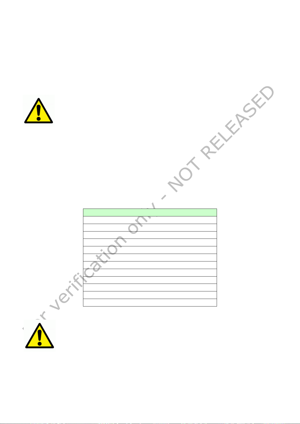
The NGP1 Computing Platform has been tes ted against rubbing forc e, long term exposure
and contrast liquid tests, with the following agents:
NaCI solution 0.9% – sodium chloride 00-236
Table 7 - Table of tested substances
WARNING: Small stain /affection has been observed after long exposure
immediately if exposed to this substances to avoid halo
discoloration.
6.1.2 To clean the screen
To removes dust and other particles, wipe the screen with a clean, soft, lint-free cloth.
For heavy duty cleaning, wipe the screen with a soft, clean cloth lightly sprayed with
prescribed cleaning or disinfectant material that should not contain wax or abrasives.
Preferably apply the cleaner to the cloth, not the screen.
VERIFICATION ONLY 43 NOT RELEASED
Page 44

WARNING: use of products on phenol base and fluids like ether, white
spirit, turpentine, trichlorethylene and perchlorethylene and iodine, can
cause damage to constituents of equipment (e.g. coated materials,
WARNING: If the is cleaned with liquids, allow the right time for a
If the display has become greasy, use isopropyl al coh ol.
6.1.3 To clean the cabinet:
For normal cleaning, use a soft cloth wetted or sprayed with disinfectant
For heavy duty cleaning, also a small brush can be used for cleaning the ventilation
apertures.
6.1.4 To clean the fan
The fan is not removable by the user. The clean of the fan could be done only by the
authorized Service Personnel.
complete drying
plastics, etc.)
6.2 Disposal
6.2.1 General warning
Your product is designed and manufactured with high qua lity materials and components,
which can be recycled and reused. Please inform yourself about the local separate
collection system for electrical and electronic products, including those marked by the
crossed-out wheel bin symbol.
6.2.2 For Countries in the European Union
This symbol indicates that this product (including the cables, plugs and accessory) must
not be disposed of with the other household waste. Instead, it is your responsibility to
dispose of your waste equipment by handing it over to a designated collection point for
the cling of waste electrical and electronic equipment. The separate collection and
recycling of your waste equipment at the time of disposal will help to conserve natural
resources and ensure that it is recycled in a manner that protects human health and the
environment. For more information about where you c an drop off your waste equipment
for recycling, please contact your local city office, or your supplier’s office.
6.2.3 For countries outside the European Union
Disposal of electrical products in co untries outside the European Union shou ld be done in
line with local regulations.
Please act according to your local rules and do not dispose of your old products with your
normal household waste.
6.2.4 Disposal of your NGP1 Computing Platform
Do not dispose of this device with general unsorted household waste.
VERIFICATION ONLY 44 NOT RELEASED
Page 45

Lithium-ion battery should never be incinerated or disposed in fire
generate a gas that may
explosion that can cause serious injuries. Never try to extinguish
Contact your local waste disposal agency for the address of the
6.2.5 Dispose of Lithium ion battery (Li-ion)
in order to avoid the risk of explosion.
Do not disassemble batteries as this can
irritate the throat and lungs. If the battery is opened, lithium in the
battery may react with moisture and generate heat or fire, which
could re sult in injury.
6.2.6 Dispose o f coin battery inside of the NGP1 C omputing Platform (Moun ted on main board):
The coin battery contain Perchlorate Material-special handling may apply,
See
www.dtsc.ca.gov/hazardouswaste/perchlorate.
Special precautions must be taken to avoid L i-ion battery fire up or
such a fire with water but only with suitable extinguisher.
nearest battery deposit site.
VERIFICATION ONLY 45 NOT RELEASED
Page 46

Note: Pressing the Power button of the device for more then five seconds
the correct shutdown procedure. This is an extreme remedy in case the
Note: You might need to practice a couple of time in to operate your
7 Troubleshooting
7.1 My NGP1 Computing Platform is not turning ON.
Make sure that the battery is properly inserted and latched or the AC adapter is fully
connected or that the unit is well docked.
Plugging the AC adapter into the DC in jack located under the protective cover on the
bottom of the unit, makes sure that the Adapter is also plugged into the wall socket.
If running with battery only, be sure that the inserted battery pack has some capacity left.
7.2 My NGP1 Computing Platform Power on LED is ON, but
nothing happens.
Make sure that the unit is not is stand-by by tapping on the screen.
As a last resort remove the power cord and the battery, wait ten seconds then insert
again the battery and power cord, restarting a power on procedure.
7.3 My NGP1 Computing Platform does not run smoothly
Simultaneous opening of too many applications will cause deterioration in application
performance.
To free up memory, close applications that are not in use, especially if they are CPU or
memory intensi ve (e.g. video playback)
If networked, Check wireless signal quality:
When the WLAN icon indicator in the icon tray is green, a wireless signal is available. If
you position your pointing device over it, you can get info abo ut the current connection
and the related signal strength.
.Otherwise, double taps the Network icon on the bar at the bottom of the screen. Choose
the Wireless Information tab to show the current connection Access Point, or try
repositioning the antenna of the access point.
7.4 How do I turn off my NGP1 Computing Platform
To end operation, press the Power / Stand-by on the NGP1 Computing Platform right side.
Or tap the “START Menu” and then choo se “Shut Down” to turn off the pad (if W indo ws is
installed).
will make a hard turn OFF preventing the Operating System to perform
device is not responding.
7.5 When I use the touch screen.
7.5.1 the cursor is not following the pen movement.
If you have just booted the system, allows more time for the touch functions to come up.
7.5.2 . the system does not respond to taps.
Be sure that you are tapping on a target (e.g. an icon) . If there is a misalignment
between pen tip and Windows indicator, please perform a new calibration, once that you
have realized that this is not due to the v iewing angle with which you are operating the
system
screen with taps. Please customize the pen a ct ion:
VERIFICATION ONLY 46 NOT RELEASED
Page 47

8 Specification
8.1 System Specifications
• CPU Intel® Atom
• CPU Speed 1.6 GHz
• RAM Size 2 GB DDR2 SDRAM
• Solis State Disk size 32 GB SSD
• Operating System Microsoft® Windows® XP Embedded
(not supplied)
8.2 Display
• Touch panel Touch Sensor
• Screen Type Transmissive TFT LCD
• Screen Size 12.1 inch / 310 mm diagonal
• Screen Resolution XGA, 1024 x 768
(4:3 aspect ratio)
• Active Screen Area 245.7 mm x 184.3 mm
• Brightness 450 cd/m2 (typical)
• Contrast Ratio 600:1 (typical)
• Display Color 256k colors (18 bits)
• Backlight LED
TM
Z530P
8.3 Connectivity and Controls
•I/O Interfaces USB ports (x 2)
VGA output
100 Mbps wired LAN on RJ-45
18 - 26.5 VDC Power Input Jack
Express card 1.2
Docking connector
•Embedded Devices I/Os IEEE 802.11 a/b/g/n WLAN
Bluetooth 2.0+ EDR
2W speakers
•Peripherals: RFID reader
2D Barcode imager (optional)
• Controls Touch screen
Waveform Viewer activation Button
VVI Emergency activation Button
(Barcode activation Button)
RFID activation Button
Bluetooth activation Button
WiFi activation Button
Power ON/OFF Button
• Indicators Battery Status LEDs (x 3)
Power status LED
Buttons LEDs (x 5)
LAN LED’s (x2)
VERIFICATION ONLY 47 NOT RELEASED
Page 48

8.4 Docking Station Connectivity
• I/O Interfaces USB ports (x 2)
18 - 26.5 VDC Power Input Jack
TBD
8.5 Power
• AC/DC Adapter In 100-240 VAC 1.5 A @ 50/60 Hz
• AC/DC Adapter Out 19 VDC 5.3 A
• Battery type Li-ion, rechargeable
• Battery capacity 4000 mAh
• Charge duration Stand-by 15 days
Operating 2hrs (min.)
8.6 Physical Characteristics
• Dimensions Width: 353.0 mm
Height: 357.0 mm
Depth: 102 mm
• Weight 3.3 kg ()
• Shock Resistance (non operating) according to Medtronic
• Dust/Water Protection IP21 (Vertical position,
rubber doors closed)
8.7 Optional Configurations
• Barcode Scanner Intermec Mod. EA15
8.8 Environmental Specifications
• Temperature (operating) 0°C to 40°C
• Temperature (transport and storage) -20 °C to 60°C
• Altitude (operating) 70 -110 kPA
• Altitude (transport and storage) 70 -110 kPA
• Humidity (operating) 15% to 93%
• Humidity (transport and storage) 15% to 93%
VERIFICATION ONLY 48 NOT RELEASED
Page 49

8.9 Applicable International Standards
• Safety ANSI/AAMI ES 60601-1:2005
EN / IEC 60601-1
CAN/CSA-C22.2 nr. 601-1-M90
• EMC FCC CFR 47 P.15 Sub B - Class A
CISPR 22 - Class A
EN / IEC 60601-1-2
EN 55011/ CISPR11 - Class A
• Radio FCC CFR 47 P.15 Sub C
EN 301 489-3
EN 300 330-2
RSS-210, SAR, IC ID
• Marks C-UL-US, CE, DEMKO, FCC
VERIFICATION ONLY 49 NOT RELEASED
Page 50

9 Options
9.1 Docking station
The NGP1 Computing Platform has a companion docking station: the Mod. 26904 ( cod:
XXXXXXXXXXXXXX)
It delivers a “grab and go” undocking process (no release buttons o r levers), allows the
user to store the unit while charging the battery and provides c onvenient desk-top acce ss
by placing the display at a comfortable height. The docking station can be powered with
the same power adapter of the NGP1 Computing Platform.
9.2 Optional additional battery pack
Additional battery packs Mod. FBT3S2P (P/N 4519 208 81321) can be purchased
9.3 Optional spare AC adapter
In case you want to have separate AC ad apter for the NGP1 Computing Platform , when
on the go, and the docking stat ion, a separate AC adapter Mod. APS100EM-190530 (P/N
9919 208 85192)can be purchased .
10 Customers care and warranty
10.1 _________________________________________________________
Contacts
FIMI s.r.l.
Via Saul Banfi , 1
21047 Saronno (VA)
Italy
Tel: +39-02-96175.1
Web site:
www.barco.com
For questions or inquiries:
TBD
VERIFICATION ONLY 50 NOT RELEASED
Page 51
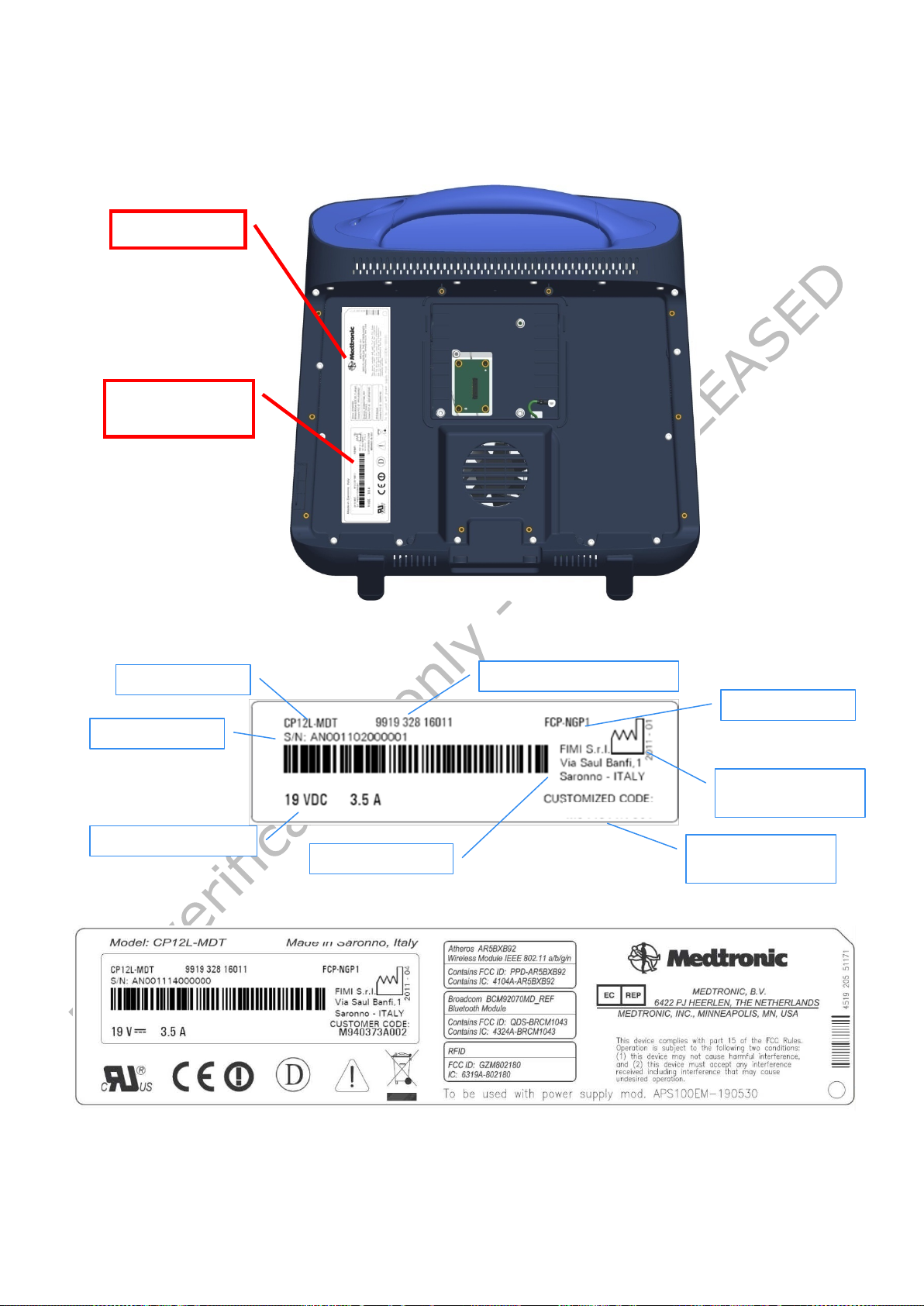
Model number
Manufacturing
Code number (12NC)
Factory address
Serial number
Power supply ra ting
Customer code
Identification
Rating label
11 Labels and stickers
A group of labels is placed on the lower part of the back of the unit.
The identification label, detailed below, is placed under a transparent window:
Here below the details of the rating label:
label
Type number
date
number
VERIFICATION ONLY 51 NOT RELEASED
Page 52

12 Y our notes
VERIFICATION ONLY 52 NOT RELEASED
Page 53

FIMI S.r.l.
Via Saul Banfi 1
21047 Saronno (VA). Italy
Note:
This Product has been designed to make it able to withstand certain mechanical stresses and /or to withstand exposure to
harsh, wet and dusty environment in accordance to the applicable industrial standards (IP grade). These measures are
taken to enhance its durability. How ever, it cannot be guaranteed that this Product w ill not be damaged when dropped or
when subjected to liquid spill or al ike. The re fo re the us er is req uired to take appropriate care of the Product and to apply the
following recommendations:
(i)Do not drop the Product, do not hit the touch screen and do not place heavy objects on the Produc t;
(ii)Do not expose the Product to moisture, dust and liq uid sprays;
(iii)Do not scratch the touch screen with sharp edge s and only us e the pr ov id ed too ls (stylus pen);
(iv)Use a dry soft cloth to clean the Product and, specificall y , the to uc h scre e n;
(v)Do not use the Product in environments exceeding the specifie d tem perature and humidity range.
1
4519 206 1084.1
Printed in Italy by FIMI srl
VERIFICATION ONLY 53 NOT RELEASED
 Loading...