


TM 230 - TM 260 - TM 300 - TM 350 - TM 320W
TM 360W - TM 420W - TM 500W - TM 650W
Instruction Manual

Istruzioni Originali
Original instructions
Übersetzung der Originalbetriebsanleitung
Notice originale
Manual original
Подлинный инструкций
2
0
0
5
0 RONCO BRIANTINO (MI) Italy
V
ia Bri
gatti, 59
Tel. +3
9 03
9 6
0
79
3
26
- Fax. +39 039 6079334
www.fimer.com - info@fimer.com

TM 230 -TM 260 - TM 300 - TM 350 - TM 320W
TM 360W - TM 420W - TM 500W - TM 650W
2006/42/CE
2006/95/CE
2004/108/CE
2002/95/CE
(RoHS)

1
2
3
4
14
7
5
15
6
16
17
18
19
108 12 139 11
NOMINAL DATA
NOMINAL DATA
WEIGHT:
DIMENSIONS:
STATIC CHARACTERISTIC:
POWER SUPPLY PROTECTION:
INPUT LOAD:
THERMAL PROTECTION:
INTERVENTION TEMPERATURE:
Overheating tests run at 40°C
WIRE DIAMETER:
OTHER TECHNICAL CHARACTERISTICS
OTHER TECHNICAL CHARACTERISTICS
1. NAME, ADDRESS AND LOGO OF THE PRODUCER
2. MODEL
3. SERIAL NUMBER
4. BLOCKS SCHEME
5. WELDING OUTPUT
6. SUITABLE FOR USE IN HIGH-VOLTAGE AREAS
7. INPUT VOLTAGE
8. PROTECTION CLASS
9. TYPE OF WELDING OUTPUT CURRENT
10. INPUT VOLTAGE
11. NOMINAL INPUT TENSION
12. MAXIMUM NOMINAL INPUT CURRENT
13. MAXIMUM ACTUAL INPUT CURRENT
14. PRODUCT STANDARDS
15. RANGE OF WELDING VOLTAGE-CURRENT
16. DUTY CYCLE
17. NOMINAL WELDING CURRENT
18. CONVENTIONAL LOAD TENSION
19. YEAR OF MANUFACTURE
4
61 Kg.
330x900x820
constant
400V +/- 10%
thermostat bimetallic
16A Delay-Fuses
Two-Pole 16A k- or C- Standard Switch
0,6 - 0,8 - 1,0 mm
TTMM 22330
0
Serial Numbe r :
6S4.230.152
Code :
Description :
Serial Number :
091079944
Fimer SpA
Via Brigatti, 59
20050 Ronco Briantino (MI)
Serial Number :
091079944
EN.60974-1
EN.60974-10
Model :
TM 230
V0=38V
da 25A / 15,25V a 220A / 25V
X
I
2
U
2
35%
220A
25V
60%
160A
22V
100%
115A
19,75V
MADE IN ITAL Y
3 - 50/60 Hz
V
1
=400V
I
1max
=12,1A
I
1ass
=7,2A
IP 21S 2009

1
2
3
4
14
7
5
15
6
16
17
18
19
108 12 139 11
NOMINAL DATA
NOMINAL DATA
WEIGHT:
DIMENSIONS:
STATIC CHARACTERISTIC:
POWER SUPPLY PROTECTION:
INPUT LOAD:
THERMAL PROTECTION:
INTERVENTION TEMPERATURE:
Overheating tests run at 40°C
WIRE DIAMETER:
OTHER TECHNICAL CHARACTERISTICS
OTHER TECHNICAL CHARACTERISTICS
1. NAME, ADDRESS AND LOGO OF THE PRODUCER
2. MODEL
3. SERIAL NUMBER
4. BLOCKS SCHEME
5. WELDING OUTPUT
6. SUITABLE FOR USE IN HIGH-VOLTAGE AREAS
7. INPUT VOLTAGE
8. PROTECTION CLASS
9. TYPE OF WELDING OUTPUT CURRENT
10. INPUT VOLTAGE
11. NOMINAL INPUT TENSION
12. MAXIMUM NOMINAL INPUT CURRENT
13. MAXIMUM ACTUAL INPUT CURRENT
14. PRODUCT STANDARDS
15. RANGE OF WELDING VOLTAGE-CURRENT
16. DUTY CYCLE
17. NOMINAL WELDING CURRENT
18. CONVENTIONAL LOAD TENSION
19. YEAR OF MANUFACTURE
Serial Number :
6S4.260.152
Code :
Description :
Serial Number :
091079944
Fimer SpA
Via Brigatti, 59
20050 Ronco Briantino (MI)
Serial Number :
091079944
EN.60974-1
EN.60974-10
Model :
TM 260
V0=38V
da 25A / 15,25V a 250A / 26,5V
X
I
2
U
2
35%
250A
26,5V
60%
190A
23,5V
100%
130A
20,5V
MADE IN ITAL Y
3 - 50/60 Hz
V
1
=400V
I
1
max
=14,8A
I
1
ass
=8,7A
IP 21S 2009
TTMM 22660
0
5
67 Kg.
330x900x820
constant
400V +/- 10%
thermostat bimetallic
16A Delay-Fuses
Two-Pole 16A k- or C- Standard Switch
0,6 - 0,8 - 1,0 mm

1
2
3
4
14
7
5
15
6
16
17
18
19
108 12 139 11
NOMINAL DATA
NOMINAL DATA
WEIGHT:
DIMENSIONS:
STATIC CHARACTERISTIC:
POWER SUPPLY PROTECTION:
INPUT LOAD:
THERMAL PROTECTION:
INTERVENTION TEMPERATURE:
Overheating tests run at 40°C
WIRE DIAMETER:
OTHER TECHNICAL CHARACTERISTICS
OTHER TECHNICAL CHARACTERISTICS
1. NAME, ADDRESS AND LOGO OF THE PRODUCER
2. MODEL
3. SERIAL NUMBER
4. BLOCKS SCHEME
5. WELDING OUTPUT
6. SUITABLE FOR USE IN HIGH-VOLTAGE AREAS
7. INPUT VOLTAGE
8. PROTECTION CLASS
9. TYPE OF WELDING OUTPUT CURRENT
10. INPUT VOLTAGE
11. NOMINAL INPUT TENSION
12. MAXIMUM NOMINAL INPUT CURRENT
13. MAXIMUM ACTUAL INPUT CURRENT
14. PRODUCT STANDARDS
15. RANGE OF WELDING VOLTAGE-CURRENT
16. DUTY CYCLE
17. NOMINAL WELDING CURRENT
18. CONVENTIONAL LOAD TENSION
19. YEAR OF MANUFACTURE
6
Serial Numbe r :
6S4.300.152
Code :
Description :
Serial Number :
091079944
Fimer SpA
Via Brigatti, 59
20050 Ronco Briantino (MI)
Serial Number :
091079944
EN.60974-1
EN.60974-10
Model :
TM 300
V0=55V
da 30A / 15,25V a 300A / 29V
X
I
2
U
2
35%
300A
29V
60%
250A
26,5V
100%
170A
22,5V
MADE IN ITAL Y
3 - 50/60 Hz
V
1
=400V
I
1max
=19,4A
I
1ass
=8,5A
IP 21S 2009
100 Kg.
520x1070x850
400V +/- 10%
0,6 - 0,8 - 1,0 - 1,2 mm
TTMM 33000
0
constant
thermostat bimetallic
16A Delay-Fuses
Two-Pole 16A k- or C- Standard Switch

1
2
3
4
14
7
5
15
6
16
17
18
19
108 12 139 11
NOMINAL DATA
NOMINAL DATA
WEIGHT:
DIMENSIONS:
STATIC CHARACTERISTIC:
POWER SUPPLY PROTECTION:
INPUT LOAD:
THERMAL PROTECTION:
INTERVENTION TEMPERATURE:
Overheating tests run at 40°C
WIRE DIAMETER:
OTHER TECHNICAL CHARACTERISTICS
OTHER TECHNICAL CHARACTERISTICS
1. NAME, ADDRESS AND LOGO OF THE PRODUCER
2. MODEL
3. SERIAL NUMBER
4. BLOCKS SCHEME
5. WELDING OUTPUT
6. SUITABLE FOR USE IN HIGH-VOLTAGE AREAS
7. INPUT VOLTAGE
8. PROTECTION CLASS
9. TYPE OF WELDING OUTPUT CURRENT
10. INPUT VOLTAGE
11. NOMINAL INPUT TENSION
12. MAXIMUM NOMINAL INPUT CURRENT
13. MAXIMUM ACTUAL INPUT CURRENT
14. PRODUCT STANDARDS
15. RANGE OF WELDING VOLTAGE-CURRENT
16. DUTY CYCLE
17. NOMINAL WELDING CURRENT
18. CONVENTIONAL LOAD TENSION
19. YEAR OF MANUFACTURE
Serial Number :
6S4.350.152
Code :
Description :
Serial Number :
091079944
Fimer SpA
Via Brigatti, 59
20050 Ronco Briantino (MI)
Serial Number :
091079944
EN.60974-1
EN.60974-10
Model :
TM 350
V0=55V
da 30A / 15,5V a 330A / 30,5V
X
I
2
U
2
35%
330A
30,5V
60%
300A
29V
100%
210A
24,5V
MADE IN ITAL Y
3 - 50/60 Hz
V
1
=400V
I
1max
=22,4A
I
1ass
=14,9A
IP 21S 2009
TTMM 33550
0
7
110 Kg.
520x1070x850
400V +/- 10%
0,6 - 0,8 - 1,0 - 1,2 mm
constant
thermostat bimetallic
20A Delay-Fuses
Two-Pole 20A k- or C- Standard Switch

1
2
3
4
14
7
5
15
6
16
17
18
19
108 12 139 11
NOMINAL DATA
NOMINAL DATA
WEIGHT:
DIMENSIONS:
STATIC CHARACTERISTIC:
POWER SUPPLY PROTECTION:
INPUT LOAD:
THERMAL PROTECTION:
INTERVENTION TEMPERATURE:
Overheating tests run at 40°C
WIRE DIAMETER:
OTHER TECHNICAL CHARACTERISTICS
OTHER TECHNICAL CHARACTERISTICS
1. NAME, ADDRESS AND LOGO OF THE PRODUCER
2. MODEL
3. SERIAL NUMBER
4. BLOCKS SCHEME
5. WELDING OUTPUT
6. SUITABLE FOR USE IN HIGH-VOLTAGE AREAS
7. INPUT VOLTAGE
8. PROTECTION CLASS
9. TYPE OF WELDING OUTPUT CURRENT
10. INPUT VOLTAGE
11. NOMINAL INPUT TENSION
12. MAXIMUM NOMINAL INPUT CURRENT
13. MAXIMUM ACTUAL INPUT CURRENT
14. PRODUCT STANDARDS
15. RANGE OF WELDING VOLTAGE-CURRENT
16. DUTY CYCLE
17. NOMINAL WELDING CURRENT
18. CONVENTIONAL LOAD TENSION
19. YEAR OF MANUFACTURE
8
Serial Numbe r :
6S4.321.152
Code :
Description :
Serial Number :
091079944
Fimer SpA
Via Brigatti, 59
20050 Ronco Briantino (MI)
Serial Number :
091079944
EN.60974-1
EN.60974-10
Model :
TM 320 W
V0=55V
da 30A / 15,5V a 300A / 29V
X
I
2
U
2
35%
300A
29V
60%
260A
27V
100%
185A
23,25V
MADE IN ITAL Y
3 - 50/60 Hz
V
1
=400V
I
1max
=18,9A
I
1ass
=11,8A
IP 21S 2009
125 Kg.
520x1070x1400
400V +/- 10%
0,6 - 0,8 - 1,0 - 1,2 mm
TTMM 332200W
W
constant
thermostat bimetallic
16A Delay-Fuses
Two-Pole 16A k- or C- Standard Switch

1
2
3
4
14
7
5
15
6
16
17
18
19
108 12 139 11
NOMINAL DATA
NOMINAL DATA
WEIGHT:
DIMENSIONS:
STATIC CHARACTERISTIC:
POWER SUPPLY PROTECTION:
INPUT LOAD:
THERMAL PROTECTION:
INTERVENTION TEMPERATURE:
Overheating tests run at 40°C
WIRE DIAMETER:
OTHER TECHNICAL CHARACTERISTICS
OTHER TECHNICAL CHARACTERISTICS
1. NAME, ADDRESS AND LOGO OF THE PRODUCER
2. MODEL
3. SERIAL NUMBER
4. BLOCKS SCHEME
5. WELDING OUTPUT
6. SUITABLE FOR USE IN HIGH-VOLTAGE AREAS
7. INPUT VOLTAGE
8. PROTECTION CLASS
9. TYPE OF WELDING OUTPUT CURRENT
10. INPUT VOLTAGE
11. NOMINAL INPUT TENSION
12. MAXIMUM NOMINAL INPUT CURRENT
13. MAXIMUM ACTUAL INPUT CURRENT
14. PRODUCT STANDARDS
15. RANGE OF WELDING VOLTAGE-CURRENT
16. DUTY CYCLE
17. NOMINAL WELDING CURRENT
18. CONVENTIONAL LOAD TENSION
19. YEAR OF MANUFACTURE
Serial Number :
6S4.361.152
Code :
Description :
Serial Number :
091079953
Fimer SpA
Via Brigatti, 59
20050 Ronco Briantino (MI)
Serial Number :
091079953
EN.60974-1
EN.60974-10
Model :
TM 360 W
V0=55V
da 30A / 15,5V a 330A / 30,5V
X
I
2
U
2
35%
330A
30,5V
60%
300A
29V
100%
210A
24,5V
MADE IN ITAL Y
3 - 50/60 Hz
V
1
=400V
I
1max
=22,4A
I
1ass
=14,9A
IP 21S 2009
TTMM 336600W
W
9
138 Kg.
520x1070x1400
costante
400V +/- 10%
termostato bimetallico
Fusibili 20A Ritardati
Int. Bipolari: 20A Curva K o C
0,6 - 0,8 - 1,0 - 1,2 mm

1
2
3
4
14
7
5
15
6
16
17
18
19
108 12 139 11
NOMINAL DATA
NOMINAL DATA
WEIGHT:
DIMENSIONS:
STATIC CHARACTERISTIC:
POWER SUPPLY PROTECTION:
INPUT LOAD:
THERMAL PROTECTION:
INTERVENTION TEMPERATURE:
Overheating tests run at 40°C
WIRE DIAMETER:
OTHER TECHNICAL CHARACTERISTICS
OTHER TECHNICAL CHARACTERISTICS
1. NAME, ADDRESS AND LOGO OF THE PRODUCER
2. MODEL
3. SERIAL NUMBER
4. BLOCKS SCHEME
5. WELDING OUTPUT
6. SUITABLE FOR USE IN HIGH-VOLTAGE AREAS
7. INPUT VOLTAGE
8. PROTECTION CLASS
9. TYPE OF WELDING OUTPUT CURRENT
10. INPUT VOLTAGE
11. NOMINAL INPUT TENSION
12. MAXIMUM NOMINAL INPUT CURRENT
13. MAXIMUM ACTUAL INPUT CURRENT
14. PRODUCT STANDARDS
15. RANGE OF WELDING VOLTAGE-CURRENT
16. DUTY CYCLE
17. NOMINAL WELDING CURRENT
18. CONVENTIONAL LOAD TENSION
19. YEAR OF MANUFACTURE
10
Serial Numbe r :
6S4.421.152
Code :
Description :
Serial Number :
091079953
Fimer SpA
Via Brigatti, 59
20050 Ronco Briantino (MI)
Serial Number :
091079953
EN.60974-1
EN.60974-10
Model :
TM 420 W
V0=55V
da 35A / 15,75V a 400A / 34V
X
I
2
U
2
35%
400A
34V
60%
360A
32V
100%
300A
29V
MADE IN ITAL Y
3 - 50/60 Hz
V
1
=400V
I
1max
=29,9A
I
1ass
=19,6A
IP 21S 2009
156 Kg.
520x1070x1400
400V +/- 10%
0,8 - 1,0 - 1,2 - 1,6 mm
TTMM 442200W
W
constant
thermostat bimetallic
25A Delay-Fuses
Two-Pole 25A k- or C- Standard Switch

1
2
3
4
14
7
5
15
6
16
17
18
19
108 12 139 11
NOMINAL DATA
NOMINAL DATA
WEIGHT:
DIMENSIONS:
STATIC CHARACTERISTIC:
POWER SUPPLY PROTECTION:
INPUT LOAD:
THERMAL PROTECTION:
INTERVENTION TEMPERATURE:
Overheating tests run at 40°C
WIRE DIAMETER:
OTHER TECHNICAL CHARACTERISTICS
OTHER TECHNICAL CHARACTERISTICS
1. NAME, ADDRESS AND LOGO OF THE PRODUCER
2. MODEL
3. SERIAL NUMBER
4. BLOCKS SCHEME
5. WELDING OUTPUT
6. SUITABLE FOR USE IN HIGH-VOLTAGE AREAS
7. INPUT VOLTAGE
8. PROTECTION CLASS
9. TYPE OF WELDING OUTPUT CURRENT
10. INPUT VOLTAGE
11. NOMINAL INPUT TENSION
12. MAXIMUM NOMINAL INPUT CURRENT
13. MAXIMUM ACTUAL INPUT CURRENT
14. PRODUCT STANDARDS
15. RANGE OF WELDING VOLTAGE-CURRENT
16. DUTY CYCLE
17. NOMINAL WELDING CURRENT
18. CONVENTIONAL LOAD TENSION
19. YEAR OF MANUFACTURE
Serial Number :
6S4.501.152
Code :
Description :
Serial Number :
091079953
Fimer SpA
Via Brigatti, 59
20050 Ronco Briantino (MI)
Serial Number :
091079953
EN.60974-1
EN.60974-10
Model :
TM 500 W
V0=55V
da 35A / 15,75V a 500A / 39V
X
I
2
U
2
35%
500A
39V
60%
430A
35,5V
100%
320A
30V
MADE IN ITAL Y
3 - 50/60 Hz
V
1
=400V
I
1max
=42,5A
I
1ass
=25,8A
IP 21S 2009
TTMM 550000W
W
11
215 Kg.
520x1070x1400
400V +/- 10%
0,8 - 1,0 - 1,2 - 1,6 mm
constant
thermostat bimetallic
32A Delay-Fuses
Two-Pole 32A k- or C- Standard Switch

1
2
3
4
14
7
5
15
6
16
17
18
19
108 12 139 11
NOMINAL DATA
NOMINAL DATA
WEIGHT:
DIMENSIONS:
STATIC CHARACTERISTIC:
POWER SUPPLY PROTECTION:
INPUT LOAD:
THERMAL PROTECTION:
INTERVENTION TEMPERATURE:
Overheating tests run at 40°C
WIRE DIAMETER:
OTHER TECHNICAL CHARACTERISTICS
OTHER TECHNICAL CHARACTERISTICS
1. NAME, ADDRESS AND LOGO OF THE PRODUCER
2. MODEL
3. SERIAL NUMBER
4. BLOCKS SCHEME
5. WELDING OUTPUT
6. SUITABLE FOR USE IN HIGH-VOLTAGE AREAS
7. INPUT VOLTAGE
8. PROTECTION CLASS
9. TYPE OF WELDING OUTPUT CURRENT
10. INPUT VOLTAGE
11. NOMINAL INPUT TENSION
12. MAXIMUM NOMINAL INPUT CURRENT
13. MAXIMUM ACTUAL INPUT CURRENT
14. PRODUCT STANDARDS
15. RANGE OF WELDING VOLTAGE-CURRENT
16. DUTY CYCLE
17. NOMINAL WELDING CURRENT
18. CONVENTIONAL LOAD TENSION
19. YEAR OF MANUFACTURE
12
Serial Numbe r :
6S4.651.152
Code :
Description :
Serial Number :
091079953
Fimer SpA
Via Brigatti, 59
20050 Ronco Briantino (MI)
Serial Number :
091079953
EN.60974-1
EN.60974-10
Model :
TM 650 W
V0=63V
da 35A / 15,75V a 600A / 44V
X
I
2
U
2
35%
600A
44V
60%
500A
39V
100%
380A
33V
MADE IN ITAL Y
3 - 50/60 Hz
V
1
=400V
I
1max
=58A
I
1ass
=34,3A
IP 21S 2009
230 Kg.
520x1070x1400
400V +/- 10%
0,8 - 1,0 - 1,2 - 1,6 - 2,0 mm
TTMM 665500W
W
constant
thermostat bimetallic
40A Delay-Fuses
Two-Pole 40A k- or C- Standard Switch

ITALIANO
USE AND MAINTENANCE MANUAL
USE AND MAINTENANCE MANUAL
Fimer S.p.a. thanks you for selecting this unit, it will prove to be a useful, problem-free
tool for many years to come if the instructions contained in this manual are followed scrupulously.
This manual must be considered as an integral part of the unit and must accompany it
when it change location or is resold.
The user must assume responsability for maintaining this manual intact and legible at all
times.
Fimer S.p.a. reserves the right to modify this manual at any time without notice.
All rights of translation and total or partial reproduction by any means whatsoever (including scanner, photocopy, film, and microfilm) are reserved and reproduction is prohibited
without the express written consent of Fimer S.p.a.
INDEX
INDEX
• WARNING SYMBOLS .................................................................................................
...................................................................................................... pag. 14, 15, 16
1. MIG WELDING ...................................................................................... pag .17
2. POWER SUPPLY CONNECTION ......................................................... pa g.1 7
3. OUTPUT CONNECTIONS .................................................................... pag. 17
4. UNIT DESCRIPTION ............................................................................ pag .18
5. INSTALLATION OF THE WELDING WIRE .......................................... pag.2 1
6. CONNECTION BETWEEN THE SEPARATE TROLLEY AND BASE ............ pag.22
7. CONNECTION OF THE GAS CYLINDER AND REGULATOR. ..................... pag.23
8. MIG TORCH .......................................................................................... pag .23
9. PREPARING FOR THE WELDING ....................................................... pag.23
10. WELDING PROCESS ......................................................................... pag.24
11. HOW TO OBTAIN THE BEST WELDING RESULTS ......................... pag.2 4
12. REGULATING THE WELDING MACHINE ......................................... pag.2 4
13. TROUBLESHOOTING ........................................................................ pag.25
14. WIRE LINER REPLACEMENT ........................................................... pag. 26
15. INSTALLATION INSTRUCTIONS FOR
INDOOR WATER COOLING SYTEM ...................................................... pag. 27
16. SPARE PARTS ................................................................................... pag. 32
17. BLOCK DIAGRAM TM 230 - TM 260 ............................................... pag. 33
18. BLOCK DIAGRAM TM 300 .............................................................. pag. 34
19. BLOCK DIAGRAM TM 350 - TM 320W - TM 360W .......................... pag. 35
20. BLOCK DIAGRAM TM 420W - TM 500W - TM 650W ...................... pag. 36
ENGLISH
DEUTSCHFRANÇAIS
ESPAÑOLРУССКИЙ
13
WARNING SYMBOLS
WARNING SYMBOLS
CAUTION
CAUTION
D
ANGER
(Indicating a hazard that could cause injury or damage)
DANGER
O
F FIRE OR EXPLOSION.
Indicating that eye protection is required to avoid
b
urns and eye damage.
TOXIC GAS
Indicating the risk of toxic gas hazards
HOT SLAG
Indicating the risk of being burned by hot slag
EYE PROTECTION
Indicating that eye protection is required to avoid flying debris
E
LECTRIC SHOCK
(Indicating the danger of electric shock)
DANGER COMPRESSED GAS
Indicating the risk of injury or death in the event of improper handl
ing or maintenance of compressed gas cylinders or regulators
IMPORTANT INFORMATION
Indicating the precautions to be taken when installing and
using the unit.
D
ISPOSAL
INFORMATION
FIRE
PRECAUTIONS
SAFETY WARNINGS
This equipment is designed solely for industrial or
professional use. As such, only experienced or ful-
ly-trained people should use the equipment. The user
and/or owner is responsible for ensuring inexperienced personnel does not have access to the equipment.
The safety information contained in this manual is a guide to
ensure you are not subjected to unnecessary risks. However,
the operator must be competent and careful at all times.
Fimer SpA declines all responsibility for injury or dama-
ge caused by inexperienced, improper or neglectful use
of its equipment.
A workman must look after his tools carefully ! Remember that
any tool or equipment can become a hazard if it is not looked
after properly.
Equipment in a state of disrepair or neglect can be dangerous. If it
does not operate properly or overheats, the electricity supply should
be removed immediately and the unit should be returned to the supplier for repair.
All equipment connected to electric power supplies can be dangerous if the manufacturers instructions are not read and obser-
ved. Read, understand and observe these safety instructions
to reduce the risk of death or injury from electric shock. Ensure that
even bystanders are aware of, and understand, the dangers that exist in the welding area.
Read this manual carefully before using your Welder.
You can then do a better and safer job.
By reading this manual you will learn more about the
possibilities, limitations and potential dangers of welding.
Retain this manual for the entire life of the equipment. It should be
kept within the operator’s reach at all times.
Fires and explosions can seriously injure or cause dama-
ge ! Read, understand and observe all safety warnings
to reduce the risk of death or injury from fire or explosion. Pay particular attention to the fact that even bystanders should
be aware of, and understand, the dangers existing in the welding area.
Remember that welding, by nature, produces sparks, hot spatter, molten metal drops, hot slag and hot metal parts that can cause fires, can
burn skin and damage eyes.
Arc rays can damage your eyes and burn your skin ! Read,
understand and observe all safety warnings to avoid dama-
ge from arc rays. Pay particular attention to the fact that
even bystanders should be aware of, and understand, the dangers existing in the welding area. Wear a protective mask and make sure bystanders do the same.
Fumes, toxic gases and vapours can be harmful ! Read,
understand and observe all safety warnings to avoid harm
from toxic welding gases. Pay particular attention to the fact that even
bystanders should be aware of, and understand, the dangers.
Carelessness while using or maintaining the compres-
sed gas cylinders or regulators can injure or kill the
operator and/or bystanders ! Read, understand and observe all safety
warnings to avoid the dangers of compressed gas. Pay particular
attention to the fact that even bystanders should be aware of, and
understand, the dangers.
HIGH VOLTAGE
The unit carries potentially lethal voltage.
The high voltage areas of the equipment have been segregated
and can be reached only by using tools that are not provided with the
Welder.
All maintenance or repair operations requiring access to such areas may
only be performed by Fimer-trained technicians.
FOREIGN OBJECTS
Never block the air vents with foreign objects and avoid
any contact with liquids. Clean using just a dry cloth. The-
se safety precautions apply even when the unit is switched off.
CABLE GAUGES
Check that all cables are appropriately gauged for
the input power required by your specific Welder.
This precaution applies also to extension cables, if used. All extension
cables must be straight. Coiled cables can overheat, becoming dangerous. Twisted or coiled cables can also cause Welder malfunction.
WEIGHT LOADS
The upper part of the Welder was not designed to withstand heavy loads. Never stand on the unit.
INSTALLATION
INSTRUCTIONS
OPERATING
INSTRUCTIONS
UNPACKING
INSTRUCTIONS
14
WELDING OPERATION
WELDING OPERATION
SAFETY INSTRUCTIONS
SAFETY INSTRUCTIONS
PERSONNEL PROTECTION
PERSONNEL PROTECTION
LOCATION
Place the Welder well away from heat sources. Place the
Welder in a well-ventilated environment. Place the Welder in
a safe, protected area. It must not be installed outdoors. Do not install the
Welder in dusty environments. Dust can get into the inner parts of the unit
and inhibit cooling. The Welder must be positioned on a flat, stable surface that extends further than the units own dimensions in all directions.
CLEAN LOCATIONS
The installation area must be kept clean and dry to be sure the Welder
fans do not draw in small objects or liquids. Not only could the equipment malfunction but a serious risk of fire outbreak could be created.
REPAIRS
Never attempt to repair the Welder yourself. Always
refer to the manufacturer or an authorized repairer.
All warranty provisions will immediately become null and void if any repair,
or attempt to repair, not specifically authorized in writing or handled by
Fimer S.p.A. is carried out. Furthermore, Fimer S.p.A. will accept no
responsibility for any malfunction or damage resulting as a consequence of such unauthorized action.
SPARE PARTS
U
se only manufacturer-recommended spare parts.
Other spare parts could cause equipment malfunction. The use of non-original spare parts will also result in the warranty provisions becoming null and void, releasing the manufacturer
from any responsibility for malfunction or damage resulting as a cons
equence of such action.
C
AUTION !
Welding processes can be dangerous for the operator and bystanders
if the safety warnings and instructions are not heeded.
WORK-AREA FLOORING
The work-area flooring MUST be fireproof.
WORK-AREA SURFACES
Work benches or tables used during welding
MUST have fireproof surfaces.
PROTECTION MASK
Wear a protective non-flammable welding mask
t
o protect your neck, your face and the sides of
your head. Keep the front lens clean and replace it if it is broken
or cracked. Place a transparent protection glass between the mask
and the welding area.
CLOTHING
Wear close-fitting, closed, non-flammable, pocketless clothing.
EXTINGUISHER
Always place an approved fire extinguisher in the immediate vicinity
of the work area. Fire extinguishers should be checked regularly.
EYE PROTECTION
NEVER look at the arc without appropriate eye protection.
FUMES AND GASES 1
Clean away paint, rust or any other dirt from the item to
be welded to avoid the creation of dangerous fumes.
FUMES AND GASES 2
NEVER weld on metals containing zinc, mercury, chromium, graphite, heavy metals, cadmium or beryllium unless
the operator and the bystanders use appropriate air-supplied respirators.
CONFINED SPACES
When welding in small environments, leave the power
source outside the area where welding will take place and
attach the grounding clamp to the part to be welded.
HUMIDITY
Never weld in wet or humid environments.
DAMAGED CABLES
Never use damaged cables. (This applies to both
the power and the welding cables.)
DAMAGED CABLES
Never remove the unit side panels. If the side panels
can be opened, always checked they are closed
tightly before starting any work.
HIGH VOLTAGE PROTECTION
HIGH VOLTAGE PROTECTION
Together with the previous instructions, the following precautions should be strictly observed
FIRE PREVENTION
FIRE PREVENTION
Together with the previous instructions, the following precautions should be strictly observed.
Welding operations require high temperatures therefore
the risk of fire is great.
TECHNICAL ASSISTANCE
The Welder must be taken to an authorized Technical Assi-
stance Centre if the equipment has been damaged in any way
or if any one of the following events occurs : liquid infiltration; damage caused by falling objects; exposure to rain or humidity (exceeding
the specified limits); malfunction; performance failure or if the equipment has been dropped.
O
VERLOAD PROTECTION
Check that the power source supplying the Welder carries the
correct voltage and is safety-protected. The power switch must open all the
p
ower supply circuits. (If a single-phase connection is used, both the live and
the neutral poles must be open. If a three-wire connection is used , all three
p
oles must be open. Four-wire circuits require all poles and neutral open).
Time-delayed fuses or K-standard circuit breakers should be used.
CABLE COLOURS
The green-yellow wire is for earthing. (Don’t use it for
a
nything else !)
INSTALLATION ENVIRONMENT
The equipment is not suitable for use in washrooms,
shower cubicles, pool areas or similar environments. If
you are obliged to use the unit in such areas, turn off all water supplies and check the area has been evacuated.
OPERATING AND/OR INSTALLATION ENVIRONMENT 3
Never use the Welder in an explosive, corrosive, abra-
sive or saline environment.
VENTILATION
Weld in a well-ventilated environment that does not have
direct access to other work areas.
E
ARTHING
If the Welder was not already supplied with a plug, connect the
earth wire first. When removing the plug, disconnect the earth
wire last.
PLUG AND POWER SUPPLY
If the Welder already has a plug attached, check that it is approp
riate for the wall-socket you intend using. Never tamper with
t
he power cable.
RELOCATION 1
Some Welders are extremely heavy therefore care should be
t
aken when relocating the unit. Check the floor or platform weight load limitations before relocating the unit if the Welder is to be used,
even only temporarily, in a non-industrial environment
OPERATING AND/OR INSTALLATION ENVIRONMENT 1
The Welder was not designed for installation or use in areas where it
could be subject to blows or vibration, such as road-vehicles, railway
carriages, cable-cars, aircraft, ships or boats or similar environments (including
cranes, conveyor-carriers or any other mobile equipment prone to vibration)
OPERATING AND/OR INSTALLATION ENVIRONMENT 2
The Welder should never be used or stored in the rain or in snow.
RELOCATION 2
Never store or move the Welder in an inclined position or on its
side.
Together with the previous instructions, the following
precautions should be strictly observed
15

CLEAN ENVIRONMENT
Remove all flammable materials away from
the work environment.
S
ERIOUS DANGER ! 1
NEVER weld in confined spaces (e.g. in a con-
t
ainer vehicle, a cistern or a storeroom etc.) where toxic, inflammable or explosive materials are, or have been, located or stored.
Cisterns, in particular, may still contain toxic, flammable or explosive gases and vapours years after they have been emptied.
SERIOUS DANGER! 3
NEVER use the Welder to melt frozen water
pipes.
SERIOUS DANGER ! 2
NEVER weld a cistern that contains (or has stored)
t
oxic, inflammable or explosive materials. They could
still contain toxic, flammable or explosive gases and vapours years
after they have been emptied. If you are obliged to weld a cistern,
ALWAYS passivate it by filling it with sand or a similar inert substance before starting any work.
WELDING ENVIRONMENT VENTILATION
Ventilate the welding environment carefully. Maintain
sufficient air-flow to avoid toxic or explosive gas accumulation.
Welding processes on certain kinds or combinations of metals can
generate toxic fumes. In the event of this happening, use air-supply respirators. BEFORE welding, read and understand the welding alloy safety provisions.
GAS TYPES
These welders use only inert (non-flammable) gases for welding
arc protection. It is important that the appropriate type of gas is
chosen for the type of welding being performed.
UNIDENTIFIED GAS CYLINDERS
NEVER use unidentified gas cylinders.
PRESSURE REGULATOR 1
NEVER connect the cylinder directly to the Welder.
Always use a pressure regulator.
PRESSURE REGULATOR 2
Check the regulator is performing its function properly.
Read the regulator instructions carefully.
PRESSURE REGULATOR 3
Never lubricate any part of the regulator.
PRESSURE REGULATOR 4
All regulators are designed for a specific type of gas.
Check the regulator is appropriate for the protective
gas to be used.
VENTILATION
VENTILATION
Together with the previous instructions, the following pre-
cautions should be strictly observed
PROTECTIVE WELDING GASES
PROTECTIVE WELDING GASES
Together with the previous instructions, the following
precautions should be strictly observed when welding
with protective gases
W
ALL AND FLOOR PROTECTION
The walls and flooring surrounding the welding
environment must be shielded using non-flammable materials. This
not only reduces the risk of fire but also avoids damage to the walls and floors during welding processes.
E
XTINGUISHER
Place an approved and appropriately-sized fire extinguisher in
the work environment.
C
heck its working order regularly (carry out scheduled inspections)
and ensure that all parties involved know how to use one.
D
AMAGED GAS CYLINDERS
NEVER use damaged or faulty cylinders.
CYLINDER RELOCATION
NEVER lift a gas cylinder by holding the regulator.
GAS CYLINDERS
Do not expose gas cylinders to excessive heat sources, sparks, hot slag or flames.
GAS HOSE 1
Check the gas hose is not damaged.
GAS HOSE 2
Always keep the gas hose well away from the work
area.
ELECTRIC SHOCK
Together with the previous instructions, the following pre-
cautions should be strictly observed to reduce the risk of
electric shock
ELECTRIC SHOCK INJURY
DO NOT touch a person suffering from electric shock if
he/she is still in contact with the cables. Switch the mains power
source off immediately THEN provide assistance.
CABLE CONTACT
Do not tamper with power cables if the mains power is still
switched on. Do not touch the welding circuitry. Welding circuitry is usually low voltage, however, as a precaution, do not touch the welder electrodes.
CABLE AND PLUG PRECAUTIONS
Check the power supply cable, plug and wall-socket regularly.
This is particularly important if the equipment is relocated often.
REPAIRS
Never attempt to repair the Welder yourself. The result would
not only cause warranty cancellation but also high danger risks.
MAINTENANCE PRECAUTIONS
Always check that the electric power supply has been discon-
nected before performing any of the maintenance operations listed in this manual ( e.g. before replacing any of the following: worn electrodes, welding wires, the wire feeder etc.)
Never point the welding gun or the electrode towards yourself
or others.
Check no power supply cables, telephone cables or other
electrical items (e.g. computer cables, control lines etc.) are
in the vicinity of the Welder.
Check there are no telephones, televisions, computers or other
transmission devices close to the Welder.
ELECTROMAGNETIC COMPATIBILITY
Make sure that people with pace-makers are not in the immediate vicinity of the Welder.
Do not use the Welder in hospitals or medical environments
(including veterinary surgeries). Make especially sure there
is no electrical medical equipment being used close to where welding is being done.
Should the Welder interfere with other apparatus, take the fol-
lowing precautionary measures:
1. Check the Welder’s side panels are securely fastened.
2. Shorten the power supply cables.
Place EMC filters between the Welder and the power source. (Contact Fimer Technical Dept. in this respect )
EMC compatibility : CISPR 11, Group 1, Class A.
16

17
ITALIANO
1. MIG WELDING
In MIG welding, a metal electrode consisting of a wire is melted in a weld pool. The
wire electrode is continuously fed by a
welding torch at a constant and controlled
speed. The torch is connected to the positive pole, while the ground cable is connected to the negative pole. When the wire
is fed and touches the workpiece, an electric arc is produced. The arc melts the wire
which is then deposited on the workpiece.
MIG welding uses a special metallic wire as
an electrode and an inert gas (CO2,
CO2/Argon mix or pure Argon) to protect
the weld pool. Welding with continuous
feeding of the wire allows using a higher
current density than that used in welding
with coated electrodes. This allows increasing the weld penetration and reducing the
number of passes required to fill the joint.
The welding unit consists of a DC power
source, a wire feeder, a torch and a ground
clamp. Each welder has two switches (13
and 14 of Fig. 1) used to regulate the welding current (the TM 230 and TM 260 models
only have Switch 13 for this purpose) and
two potentiometers (1 and 9 of Fig. 1) to
respectively regulate the welding time and
wire speed. The welding current and wire
speed must be regulated taking into consideration the thickness of the workpiece to be
welded. Thicker pieces require a higher
welding current and higher wire speed. The
wire speed can be adjusted during welding
to obtain better results.
IMPORTANT: The welding machine must
only be used by trained personnel.
All the TM welding machines are wire
welders produced with advanced technology that makes them extremely reliable. In
fact, minimal maintenance is required to
ensure long life of the equipment without
any problems.
The user-friendliness of the welding
machine allows for rapid interchangeability
of operators.
For an excellent welding performance, it is
recommended to use a welding spray. This
will increase the sealing capacity and
reduce weld spatter.
2. POWER SUPPLY CONNECTION
Before connecting the machine, check the
voltage, number of phases and power frequency. The admissible power supply voltage is reported in the “Technical
Specifications” section of this manual and
in the machine’s rating label. Make sure
there is sufficient power to run the
machine. The “Technical Specifications”
section of this manual contains information
on the type of line protection devices to
use. The machine comes with a specific
power cord which should not be extended.
If an extension cord is necessary, use one
that has the same or a larger cross section
than the machine’s cord depending on the
length of the cord.
3. OUTPUT CONNECTIONS
The welding cables are connected with a
quick coupling system that uses special connectors. The ground cable must first be connected to its connector (15 or 16 of Fig.1) and
then the torch cable (19 di Fig. 1). This connector also allows connecting the electrical
contacts of the torch and the hose that carries
the welding gas to the torch.
Refer to the following sections for more information on the connections to be carried out
before proceeding with the welding.
ESPAÑOL
FRANÇAIS DEUTSCH
ENGLISH
РУССКИЙ

19
12
13
14
18
17
16
19
18
17
15b
15a
20
12
13
14
20
20
TM 320W - TM 360W
TM 420W TM 500W TM 650W
9
19
18
17
14
13
10
1
11
8
6
7
2
5
TM 3 50
TM 3 00
1
9
6
8
7
11 10
15b
15a
14
14
15c
20
Fig. 1: FRONT VIEW
4. UNIT DESCRIPTION
TM 230 - TM 260
8
9
1
11
TM 320W - TM 360W - TM 420W - TM 500W - TM 650W
10,12
13
19
16
3
4
20
15b
15a
7
12
18

19
ITALIANO
FIGURE 1
1. TIMER SPOT: Sets the maximum welding
time from 0 to 20 seconds (if the torch button is
kept pressed for a longer period, the welding
duration is automatically interrupted)
2. DISPLAY FOR VISUALISING the value of
the welding current or voltage: Press button 3
to switch-over between the current and voltage
value.
3. VOLTAGE/CURRENT SWITCH: see point 2
4. WIRE FEED BUTTON: Allows the welding
wire to be fed without pressing the torch button.
5. 4T LED: this light turns on when the machine
is operating in 4T mode.
6. 2T/4T OPERATING MODE SELECTOR:
When the 2T (two-stroke) mode is selected,
press the torch button to start the welding
process and wire feed.
When the 4T (4-stroke) mode is selected, press
the torch button to start the welding process and
wire feed, and press this button again to stop the
welding process.
7. BURN BACK: Accurately adjusts the time during which the current is maintained in the welding circuit after the torch button has been
released (this allows safely separating the electrode from the workpiece).
This adjustment must be made using a screwdriver, preferably in plastic (turn in a clockwise
direction to increase the time).
8. SOFT START: Sets the departure ramp of the
wire speed: use a screwdriver (preferably in
plastic) to set the time of the ramp (turn in a
clockwise direction to increase the time).
9. WIRE SPEED CONTROL: Regulates the outgoing speed of the wire by controlling the motor
speed.
10. MACHINE IN OPERATION INDICATING
LIGHT
11. THERMAL PROTECTION INDICATING
LIGHT: Turns on when the machine is overheat-
ing and the exit is interrupted. This usually
occurs if the intermittence factor of the machine
is exceeded. Make sure the air grills positioned
on the back and front of the machine are not
obstructed and leave the machine running to
allow the internal components to cool down; normal welding operations can be resumed when
this LED turns off.
If the welding machine is equipped with a
cooling unit, the LED may also turn on if the
cooling liquid does not circulate correctly
(see paragraph 14).
12. ON-OFF SWITCH: Turns the machine on
a
nd off
13. WELDING LEVEL SWITCH: Allows selecting the welding current according to the thickness of the material to be welded.
14. SWITCH FOR CHANGING THE WELDING
CURRENT RANGES:
TM 230, 260: not present
TM 300, 350, 320W, 360W:
- in the MIN position, turn switch 13 to move the
welding current from the minimum value to the
value halfway between the minimum and maximum values.
- in the MAX position, turn switch 13 to move the
welding current from the halfway value to the
maximum value.
The combination of the 10 positions of switch 13
and 2 positions of switch 14 allows selecting
from 20 possible welding currents.
TM 420W, 550W, 650W:
- in the MIN position, turn switch 13 to move the
welding current from the minimum value to onethird of the maximum value.
- in the MED position, turn switch 13 to move the
welding current from one-third of the maximum
value to two-thirds of the maximum value.
- in the MAX position, turn switch 13 to move the
welding current from two-thirds of the maximum
value to the maximum value.
The combination of the 10 positions of switch 13
and the 3 positions of switch 14 allows selecting
from 30 possible welding currents.
15a. GROUND CONNECTOR: The minimum inductance value is inserted when the
negative welding cable is connected to this
connector.
Only use this connector (which guarantees the
best performances) during spray-arc welding
(see paragraph 10).
15b. GROUND CONNECTOR: A higher inductance value is inserted when the negative welding cable is connected to this connector.
Only use this connector when the machine is
operating in short-arc mode (see par. 10).
15c. GROUND CONNECTOR (only for TM
420W, 500W, 650W): The highest inductance
value is inserted when the negative welding
cable is connected to this connector.
Only use this connector when the machine is
operating in short-arc mode (see par.10).
16. GROUND CONNECTOR: Allows connecting
the negative cable to the workpiece (TM230,
TM260 and TM300).
РУССКИЙ
ESPAÑOL
FRANÇAIS DEUTSCH
ENGLISH

21
23
24
Fig.2A
28
27
29
26
TM 230 - TM 260
23
24
22
33, 34
25
21
F
ig.2A
28
27
29
26
TM 300- TM 350
Fig.2A
28
27
27
29
26
20
TM 320W
TM 360W - TM 420W
TM 500W - TM 650W
17. H²O out: Only to be used with the “liquid
cooling” option
18. H²O in: Only to be used with the “liquid cooling” option
19. TORCH QUICK CONNECTOR: Output connection (positive) for the welding circuit, electrical
contacts and torch gas.
FIGURE 2
20. AIR INLET
21. GAS PIPE CONNECTOR: to be connected
to the pressure reducer of the cylinder
22. INPUT CABLE: connect this cable to the
mains power supply.
23. WIRE SPOOL
24. WIRE FEED UNIT: for more details refer to
Figure 2A.
25. SUPPORT FOR WELDING GAS CYLINDER.
26. WIRE ENTRANCE OF THE WIRE-FEED
MOTOR
27. WIRE PRESSURE REGULATOR: Allows
regulating the tension of the welding wire
28. WIRE-FEED MOTOR
29. WIRE-FEED ROLLERS
30. ELECTRICAL CONNECTOR FOR THE
SIGNALS (cable bundle) (separate trolley)
Fig. 2: SIDE VIEW
22
20
25
30
23 24
31
32
33, 34
22
21
35
36
20
37, 38
25
20

21
ITALIANO
31. POWER ELECTRICAL CONNECTOR
(cable bundle) (separate trolley)
32. GASE TUBE CONNECTION (cable bundle)
(separate trolley) (Black)
33. CONNECTION FOR LIQUID COOLING
(separate trolley) (Red)
34. CONNECTION FOR LIQUID COOLING
(separate trolley) (Blue)
35. ELECTRICAL CONNECTOR FOR THE
SIGNALS (cable bundle) (Base)
36. ELECTRICAL CONNECTOR FOR THE
POWER (cable bundle) (Base)
37. CONNECTION FOR LIQUID COOLING
(Base) (Blue)
38. CONNECTION FOR LIQUID COOLING
(Base) (Red)
5. INSTALLATION OF THE WELDING
WIRE
Follow the instructions below to install the welding wire (refer to Figure 2A).
Attention: before installing the welding wire,
always remove the gas nozzle (Fig. 3A) and
wire-guide tip (Fig. 3B) from the welding torch.
1. Disconnect the power cord from the mains
outlet (22 of Fig. 2 and 4C).
2. Unscrew the knurled knob positioned in the
middle of the welding wire spool (23 of Fig. 2)
and, if necessary, remove the used spool.
3. Remove the plastic wrapper from the new
spool and place the spool on the special spool
holder (23 of Fig. 2). Reassemble the knurled
knob. The allen screw (M8) positioned underneath the knurled knob forms the braking system
of the wire spool. Tighten the allen screw in order
to obtain the best braking result. Too much pressure may cause excessive braking which in turn
may block the wire-feed motor. Too little pressure
may not allow the wire spool to immediately stop
at the end of the welding.
4. TM 230, TM 260: Unscrew the knob of the
wire-feed unit (27 of Fig.2A) and lift the upper
feed roll (29 of Fig. 2A).
TM 300, TM 350: Unscrew the knob of the wirefeed unit (27 of Fig.2A) and turn outwards. This
will lift the upper feed rolls (29 of Fig. 2A).
TM 360W, TM 420W, TM 500W, TM 650W:
Unscrew the knobs of the wire-feed unit and turn.
This will lift the upper feed roll (29 of Fig. 2A)
Remove any wire left over from the previous
welding.
5. Insert the wire into the little in-feed tube (26 di
Fig. 2A) of the wire-feed motor and let it slide
under the wire-feed rolls.
6. Lower the upper rolls(29 of Fig. 2A) and tight-
en the plastic knob (27 of Fig. 2A) of the wire
pressure regulator.
Tighten slightly. If tightened too much, the wire
Fig.3A
Fig.3B
GA S NOZZL E
WIRE-FEEDER GUIDE
Fig.3
TORCH CABLE
ENGLISHESPAÑOL
РУССКИЙ FRANÇAIS
DEUTSCH

may get blocked which could
cause motor damage. If not tightened enough, the
rolls may not be able to feed the wire.
For the TM 360W, TM 420W, TM 500W, TM
650W machines, repeat this operation for the second knurled knob.
N.B. When changing the diameter of the wire,
make sure the correct groove of the wire-feed roll
is facing towards the inside of the machine.
To do this, check that the value corresponding to
the wire diameter and wire type being used is legible (facing towards the outside of the machine).
Remember that the rolls with a “V-shaped” slot
are suitable for feeding iron or steel wires.
Rolls with a “U-shaped” slot are suitable for aluminium wires.
Attention: Before proceeding with the next steps,
make sure the torch cable (Fig. 3) is tight and that
no angles or burrs are present on the welding
wire. Please follow these precautions to ensure
the correct operation of the wire guide.
6. CONNECTION BETWEEN THE SEPARATE TROLLEY AND BASE
Before carrying out the operations described in
the following paragraphs, connect the separable trolley and the machine base for the TM
360W - TM 420W - TM 500W -TM 650W
machines.
N.B. The red and blue tubes (33 and 34 of Fig
4A) are only supplied with some machines.
1. Find the connection side as shown in
Figure 4B.
2. Connect the power electrical connector (36 of
Fig 4B) to the appropriate coupler (36 of Fig 4C).
3. Connect the signal connector (35 of Fig 4B) to
the appropriate coupler (35 of Fig 4C).
Wiew Feeder
Base
32 (black)
34 (blue)
33 (red)
38 (red)
37 (blue)
35 36
gas
30
31
Fig. 4C
Fig. 4A
Fig. 4B
36
38
37
35
22
21
30
31
34
33
32
22

23
ITALIANO
4. Connect(if present) the quick connector (38 of
Fig 4B) of the red tube to the quick coupler (38
of Fig 4C).
5. Connect(if present) the quick connector (37 of
Fig 4B) of the blue tube to the quick coupler (37
of fig 4C).
6. Connect the gas hose (Fig 4B) to the cylinder
(Fig 5) by carefully following the instructions out-
lined in Paragraph 7.
7. Take hold of the other end of the cable bundle
(Fig 4A).
8. Connect the power electrical connector (31
of Fig 4A) to the appropriate coupler (31 of
Fig 4C).
9. Connect the signal connector (30 of fig 4A) to
the appropriate coupler (30 of Fig 4c).
10. Connect the quick connector of the black gas
hose (32 of Fig 4A) to the appropriate coupler
(32 of Fig 4C).
11. Connect the quick connector of the red tube
(33 of Fig 4A) to the appropriate coupler (33 di
Fig 4C).
12. Connect the quick connector of the blue tube
(34 of Fig 4A) to the appropriate coupler (34 of
Fig 4C.
7. CONNECTION OF THE GAS CYLINDER AND REGULATOR (see Fig 5)
1. Connect the pressure regulator (2) to the gas
cylinder (3).
Tighten the connecting nut (6) of the regulator (2)
to the cylinder (3).
Do not over-tighten because this may damage
the valve (1) of the cylinder (3).
2. Connect the gas hose (4) to the regulator (2)
by securing it with a tube clamp (5).
3. Make sure the gas hose is correctly connected to the welding machine.
4. Open the valve (1) of the gas cylinder (3).
Press the torch button and make sure the gas
flows correctly.
Attention: The cylinders contain highly pressurized
gas. Handle with care. Improper handling could lead
to serious accidents. Do not place the cylinders on top
of each other and do not expose to excessive heat,
flames or sparks. Do not allow the cylinders to strike
against each other. Contact your gas supplier for more
information on the use and handling of the cylinders.
Attention: Do not use the cylinder if you find
oil leaks, grease or damaged parts.
Immediately contact your gas supplier if these
conditions exist.
8. MIG TORCH
It is recommended to periodically check the condition of the welding torch. In particular, check
the gas nozzle (Fig 3A) and wire-guide tip (Fig
3B). These parts must be kept clean and intact.
Replace the wire-guide when the wire does not
run smoothly.
9. PREPARING FOR THE WELDING
1. Connect the welding machine to the mains
power.
2. Make sure the polarity of the torch and ground
cables are positioned correctly.
3. Connect the ground terminal to the workpiece,
making sure the contact is good.
Fig. 5
2
5
3
4
5
4
3
1
2
6
1
РУССКИЙ
ESPAÑOL
FRANÇAIS DEUTSCH
ENGLISH

10. WEL D ING PR O CESS
The TM230 and 260 welding machines have 11 regulating positions (13 of Fig. 1), the TM300, 350,
320W and 360W machines have 20 regulating positions (13 and 14 of Fig. 1) and the TM420W, 500W
and 650W welding machines have 30 regulating positions (13 and 14 of Fig. 1). The choice of the best
current is determined by the thickness of the material to weld. Refer to the following table for setting
the correct welding current.
11. HOW TO OBTAIN THE BEST
WELDING RESULTS
1. During welding, keep the torch at a 45° angle
from the workpiece. Keep the gas nozzle (Fig.
3A) at around 6 mm from the workpiece.
2. Continuously move the torch.
3. Do not weld in the presence of strong wind.
Strong wind could carry away the gas from the
weld pool and lead to porous welding.
4. Keep the wire clean: never use rusty wires.
5. Do not fold or twist the torch cable.
6. When changing the wire spool, clean the wireguide tube with compressed air.
7. Periodically remove any dust from the air
inlets using low-pressure compressed air.
Always direct the jet of air from the inside
of the machine towards the outside in order
to prevent dirt from being pushed inside the
welding machine.
12. REGULATING THE WELDING
MACHINE
Once the welding current has been set
according to the instructions in paragraph
9, keep the length of the electrical arc
between 5 and 10 mm and adjust the wire
speed to obtain the best welding result.
Carry out some test welds on a metallic
sheet that has been cleaned of any coating,
rust or paint.
NOTE: When the torch button is pressed, the following three functions are performed:
- gas flow;
- wire feed;
- welding current.
Start welding at a high wire speed and then gradually reduce the speed via the potentiometer (9
of Fig. 1).
Continue to reduce the wire speed and listen to
the sound produced. The sound will go from a
crackling noise to a strong and regular buzzing
noise (similar to the sound of oil being fried).
This buzzing sound indicates that the correct
wire speed has been reached for the workpiece. Each time the current is adjusted, reset
the wire speed.
Always start from the highest wire speed. This
operation prevents damaging the tip of the torch
during welding.
SPESSORE DEL PEZZO DIAMETRO FILO CORRENTE DI SALDATURA ARCO
mm mm A
0.8 - 1.0 0.6 - 0.8 60 - 100
Short - Arc
1.5 - 2.0 0.8 - 1.0 80 - 120
Short - Arc
2.0 - 3.0 1.0 - 1.2 100 - 130
Short - Arc
3.0 - 4.0 1.2 - 1.6 120 - 200
Short - Arc
> 4.0 1 150 ÷ 200
Spray - Arc
> 4.0 1.2 200 ÷ 300
Spray - Arc
> 4.0 1.6 300 ÷ 400
Spray - Arc
24

25
ITALIANO
The most common problems you may encounter and the relative solutions are listed below:
13. TROUBLESHOOTING
РУССКИЙ
ESPAÑOL
FRANÇAIS DEUTSCH
ENGLISH
DEFECT CAUSE SOLUTION
Welder does not start. 1) Make sure that there is vol-
tage in the supply mains
1) Switch-on the supply mains
The wire does not feed when the
wire-feeder roller rotates
1) Dirt on the tip of the wirefeeder
1) Blow with compressed air,
replace nozzle
2) Excessive spool torque. 2) Loose
3) Faulty torch. 3) Check wire-feeder liner.
Jerky or intermittent wire-feed. 1) Faulty gas nozzle. 2) Replace
2) Scorched gas nozzle. 2) Replace
3) Dirt in wire-feeder roller
groove.
3) Clean
4) Worn wire-feeder roller groove 2) Replace
Arc cut-out 1) Loose earth clamp grip. 1) Tighten clamp grip
2) Short circuit between contact
nozzle and gas hose.
2) Clean or replace contact
nozzle and wire-feed nozzle
Welder cuts out after prolonged
use
1) Unit overheated and thermal
protection device has set in
1) Leave the unit to cool down
for at least 1-20 minutes.
Porous welds 1) Lack of shielding gas caused
by build-up in gas nozzle
1) Clean away build-up
2) Incorrect torch angle 2) The air gap between the torch
and the workpiece must be 5-10 mm.
Ensure 60° torch angle.
3) Gas shortage 3) Increase gas flow
4) Damp workpieces 4) Dry workpieces with hot-air
gun or suchlike
5) Welding Arc too long 5) Shorten the arc
Hot cracks 1) Damp workpieces 1) Clean
2) Welding with very high heat
supply
2) Decrease the welding current
3) Impure welding wire 3) Change the welding wire
4) Base material with high con-
tent of carbon, sulphur and other
imputities
Insufficient penetration 1) current too low 1) increase the current
2) Inconstant wire feeding 2) See the above paragraph
3) Edges too apart from each
other
4) Bevel too small
Insufficient melting 1) Abrupt movements of the torch 1) Move the torch smoothly.
2) Non-optimized inductance value 2) Change the inductance value.
3) Oxidized workpieces 3) Clean
Lateral indentations 1) Excessive welding speed 1) Decrease the welding speed
Breakages 1) Unsuitable wire 1) Change the type of wire
2) Bad quality of the workpieces
Excessive splashes 1) current too high 1) Decrease the current value
2) Non-optimized inductance value 2) Increase the inductance value
3) torch too inclined 3) Straighten the torch

• Gun side: remove the gas nozzle (A)
• Unscrew the wire liner tip and the gas diffuser (B)
• Connector side (C): grab the end of wire liner using a plier and start to extract the wire liner
• Complete the extraction of the wire liner (G)
A
B
C
D
E
F
• Insert the new wire liner and push up to end (H)
• Now rescrew the diffusor on the gun (B)
G
H
14. WIRE LINER REPLACEMENT
26

27
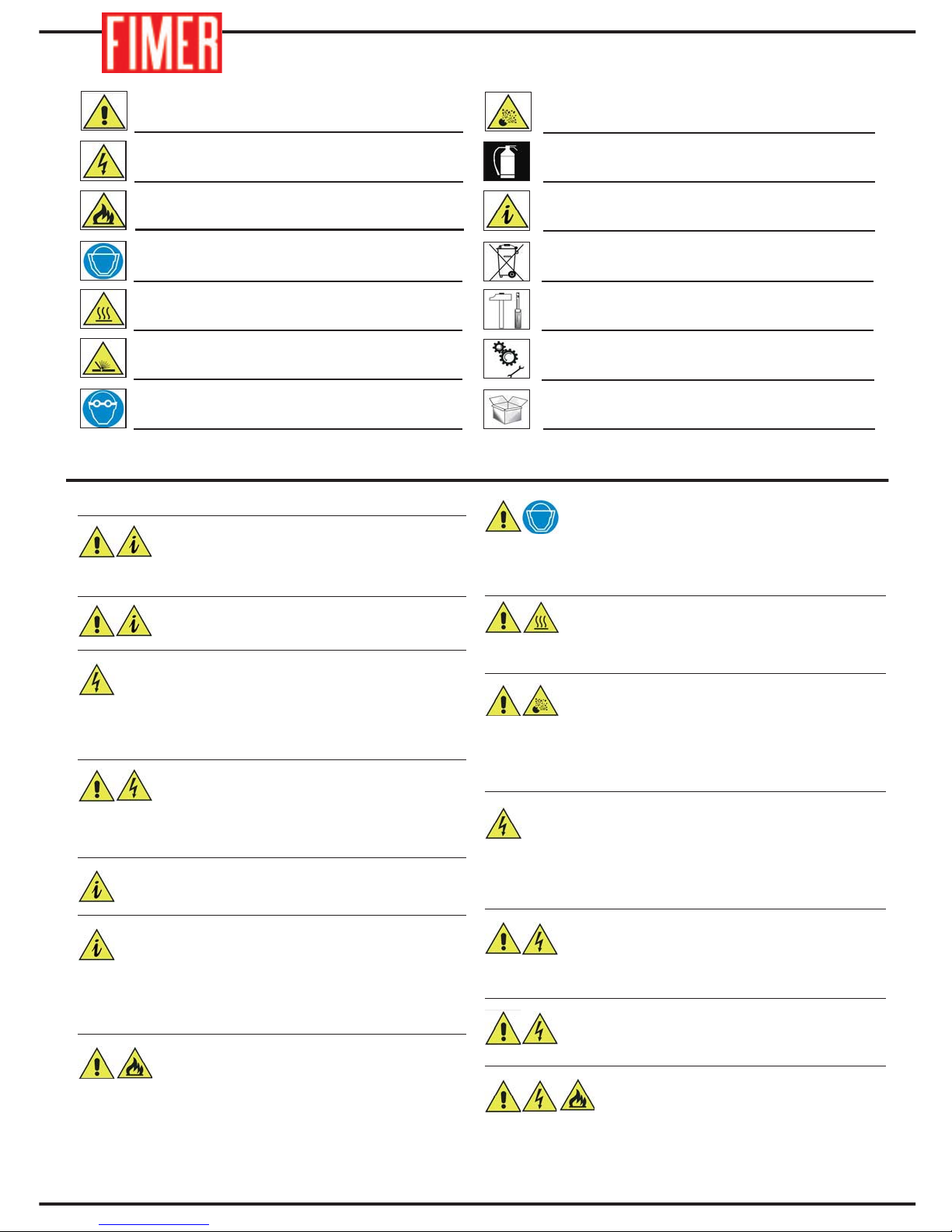
1. Using a screwdriver, remove the eyebolt on
the back of the appliance.
2. Remove the 14 black cross-head screws
which fasten the back wall.
3. Slide off the back wall.
4. Remove the MATE-N-LOCK connector posi-
tioned on the back.
15. INSTALLATION INSTRUCTIONS FOR INDOOR WATER COOLING SYTEM
РУССКИЙ
ESPAÑOL
FRANÇAIS DEUTSCH
ENGLISH
ITALIANO

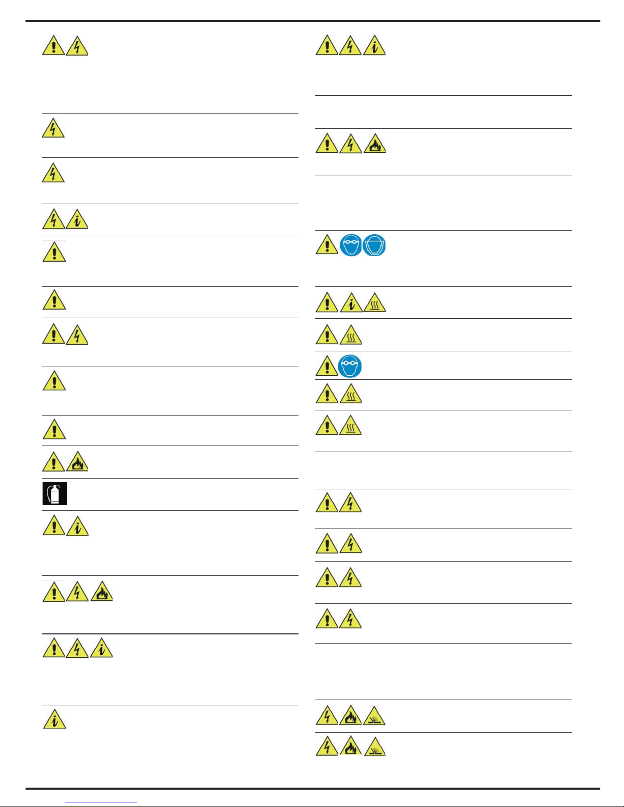
5. Free the hexagonal hole.
6. Take the control unit of the cooling system.
7. Position the control unit so that its resting sur-
face lines up with the outer most side of the
machine. Refer to the figure.
8. Connect the MATE-N-LOCK connector of the
control unit to the special connector located on
the back of the appliance.
28
29
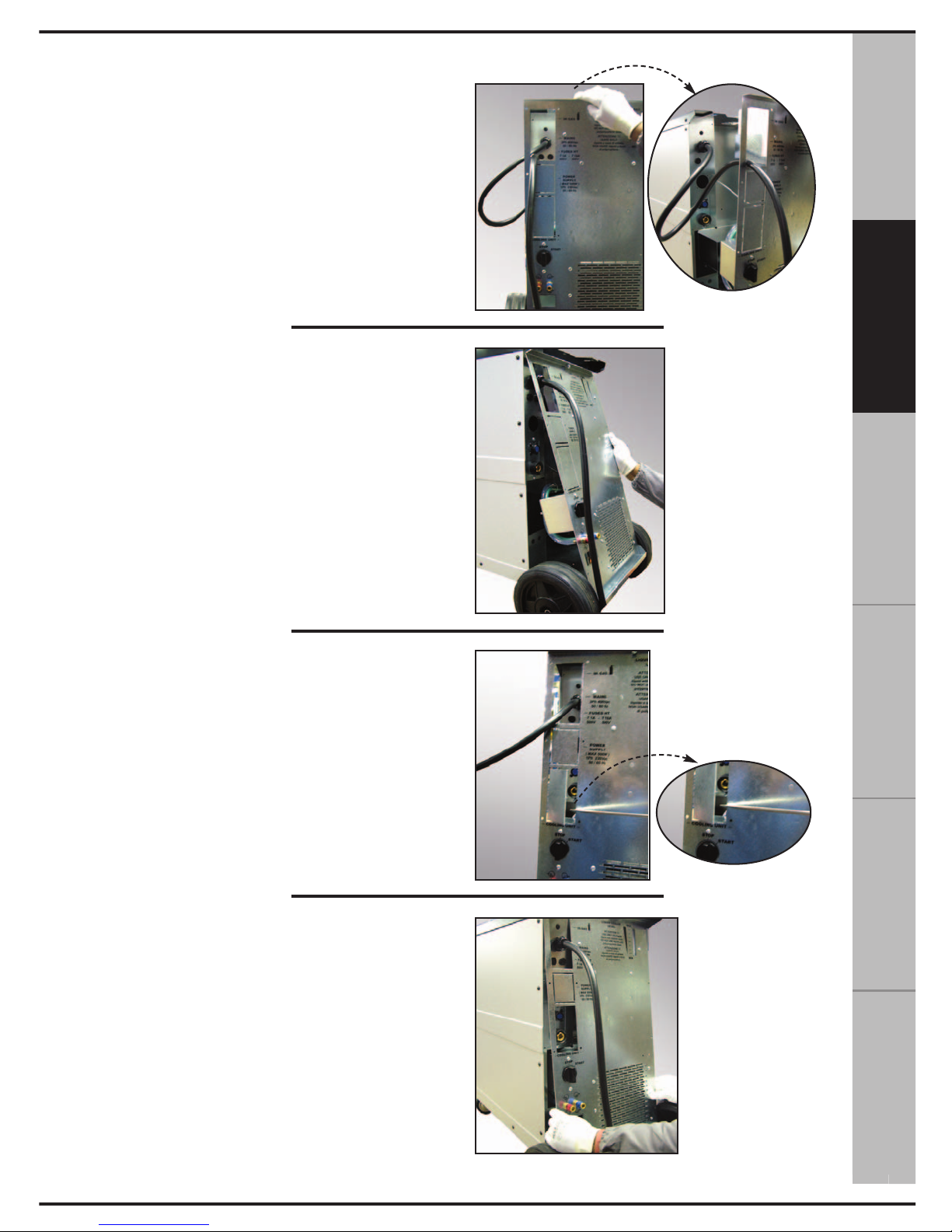
9. Slide through the power cord.
10. Position the top part of the control unit
against the upper side of the machine wall. Refer
to the figure.
In this operation, carefully check that none of the
tubes are crushed against the wall of the control
unit and the inside walls of the apparatus.
11. Free the second window located on the back
of the control unit.
12. Position the wall of the control unit so that it
rests perfectly against the back part of the
machine.
РУССКИЙ
ESPAÑOL
FRANÇAIS DEUTSCH
ENGLISH
ITALIANO
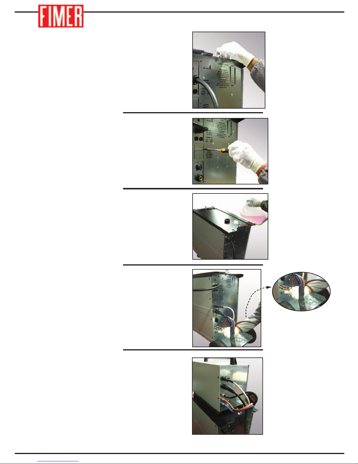
13. Replace the eyebolt.
14. Reinsert the 14 screws that were removed.
15. Fill the cooling circuit with cooling liquid.
16. Use a cable band to connect all the cables to
the back wall as shown in the figure.
17. Attach the trolley separated from the
machine and connect the five cables wrapped
up in the band.
30
31
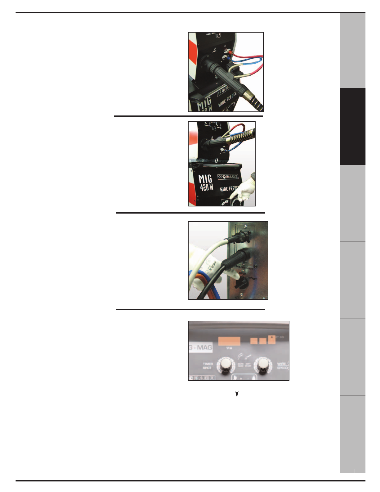
18. Connect the torch supplied with the
unit. Make sure the cooling tubes are
closed correctly.
19. Turn on the appliance via the switch positioned on the front of the machine. “0” indicates
that the machine is OFF, and “1” indicates that
the machine is ON.
20. Turn on the control unit by turning the switch
from “STOP” to “START”.
21. Wait for the tubes to be filled with the cooling
liquid, check the tank level, if necessary, add
more liquid.
22. Wait for the yellow LED located on the front
of the trolley to turn off.
If the yellow LED does not turn off:
- Check the level of the cooling liquid inside the
tank
- Make sure the cable band is not tangled, thereby preventing the liquid from circulating.
- Make sure the internal tubes are not crushed.
If so, repeat the operations described in point 10.
N.B. If the problem persists, contact an
Authorised Service Centre.
РУССКИЙ
ESPAÑOL
FRANÇAIS DEUTSCH
ENGLISH
ITALIANO
11

1. unit control card
2. auxiliary transformer
3. on/off switch
4. fan
5. rectifier
6. power transformer
7. 2/3 position switch
8. 7 position switch
9. inductance
10. wire-feeder motor
11. wire-feeder
1
8
7
10
10
11
TM 230,260
TM300, 350
2
3
6
9
5
4
11
8
2
3
6
5
9
10
11
4
7
1
2
3
4
5
6
8
16. SPARE PARTS
1
32
TM 320W - TM 360W - TM 420W
TM 500W - TM 650W

33
ENGLISH
DEUTSCHFRANÇAIS
ESPAÑOL
РУССКИЙ
ITALIANO
17. BLOCK DIAGRAM TM230-TM260
1. Contactor
2. Current switch
3. Current transformer
4. Rectifier bridge
5. Output connectors
6. Control board
6a Wire speed regulation
6b Soft Start selection
6c Burn Buck selection
6d Welding duration regulation
7. Wire feeder motor
8. Gas solenoid valve
9. Thermostat
10. Overheating warning
11. Fan
12. Auxiliary transformer
13. ON/OFF switch
14. ON welding machine lamp

1. Contactor
2a. Current switch
2b. Current range selector
3. Power transformer
4. Rectifier bridge
5. Output connectors
6. Control board
6a Wire speed regulation
6b Soft Start selection
6c Burn Buck selection
6d Welding duration regulation
7. Wire feeder motor
8. Gas solenoid valve
9. Thermostat
10. Overheating warning
11. Fan
12. Auxiliary transformer
13. ON/OFF switch
14. ON welding machine lamp
18. BLOCK DIAGRAM TM300
34

35
ENGLISH
DEUTSCHFRANÇAIS
ESPAÑOL
РУССКИЙ
ITALIANO
19. BLOCK DIAGRAM TM350 - TM320W - TM360W
1. Contactor
2a. Current switch
2b. Current range selector
3. Power transformer
4. Rectifier bridge
5. Smoothing inductance output
6. Output connectors
7. Control board
7a Wire speed regulation
7b Soft Start selection
7c Burn Buck selection
7d Welding duration regulation
8. Wire feeder motor
9. Gas solenoid valve
10. Thermostat
11. Overheating warning
12. Fan
13. Auxiliary transformer
14. ON/OFF switch
15. ON welding machine lamp

36
20. BLOCK DIAGRAM TM420 - TM500W - TM650W
1. Contactor
2a. Current switch
2b. Current range selector
3. Power transformer
4. Rectifier bridge
5. Smoothing inductance output
6. Output connectors
7. Control board
7a Wire speed regulation
7b Soft Start selection
7c Burn Buck selection
7d Welding duration regulation
8. Wire feeder motor
9. Gas solenoid valve
10. Thermostat
11. Overheating warning
12. Fan
13. Auxiliary transformer
14. ON/OFF switch
15. ON welding machine lamp

37
ENGLISH
DEUTSCHFRANÇAIS
ESPAÑOL
РУССКИЙ
ITALIANO
.................................................................................................................................................
.................................................................................................................................................
.................................................................................................................................................
.................................................................................................................................................
.................................................................................................................................................
.................................................................................................................................................
.................................................................................................................................................
.................................................................................................................................................
.................................................................................................................................................
.................................................................................................................................................
.................................................................................................................................................
.................................................................................................................................................
.................................................................................................................................................
.................................................................................................................................................
.................................................................................................................................................
.................................................................................................................................................
NNOOTTEE

.................................................................................................................................................
.................................................................................................................................................
.................................................................................................................................................
.................................................................................................................................................
.................................................................................................................................................
.................................................................................................................................................
.................................................................................................................................................
.................................................................................................................................................
.................................................................................................................................................
.................................................................................................................................................
.................................................................................................................................................
.................................................................................................................................................
.................................................................................................................................................
.................................................................................................................................................
.................................................................................................................................................
.................................................................................................................................................
38
NNOOTTEE

ESPAÑOL FRANÇAIS
ENGLISH
ITALIANO
DEUTSCH
P
er RAEE s’intendono i rifiuti di Apparecchiature Elettriche ed Elettroniche (AEE) incluse di tutti i componenti,i sottoinsiemi
ed i materiali di consumo che sono parte integrante del prodotto nel momento in cui si assume la decisione di disfarsene.
L
a Legislazione prevede la suddivisione in 2 categorie principali chiamate RAEE PROFESSIONALI o RAEE DOMESTICI.
Per RAEE PROFESSIONALI s’intendono tutti i rifiuti di apparecchiature elettriche ed elettroniche destinate ad uso prettamente industriale.
Per RAEE DOMESTICO s’intendono tutti i generatori ad alimentazione monofase con corrente di uscita MAX <= 200A
c
on i loro accessori.
P
er lo smaltimento di un RAEE DOMESTICO si avranno 2 possibilita’:
a)Nel caso si decidesse di comprare una nuova apparecchiatura equivalente l’utilizzatore potrà consegnarlo al distribu-
tore il quale dovrà ritirarlo gratuitamente.
b)Dovrà depositarlo nella piazzola Comunale, nel contenitore o apposita area identificata come “RAGGRUPPAMENTO 4”.
Per lo smaltimento di un RAEE PROFESSIONALE alla data di redazione del Manuale di istruzioni non essendo ancora
definitiva l’applicazione della Normativa si prega di contattare il distributore e/o Il costruttore per informazioni in merito allo
smaltimento.
A
LLA DATA DELLA REDAZIONE DEL PRESENTE MANUALE D’ISTRUZIONI QUESTE INFORMAZIONI SONO DA
RITENERSI NON DEFINITIVE IN QUANTO SUSCETTIBILI DI POSSIBILI MODIFICHE SECONDO GLI OBBLIGHI
L
EGATI AL DECRETO LEGISLATIVO N° 151/2005 CHE OTTEMPERA LA DIRETTIVA 2002/96/CE.
This product contains electrical or electronic materials.
The presence of these materials may, if not disposed of properly, have potential adverse affects
on the environment. Presence of this label on the product means it must not be disposed of in
normal household waste and must be disposed of separately.
As a consumer you are responsible for ensuring that this product is disposed of properly. If your
supplier offers a disposal facility please use it or alternatively contact your local authority/council to find out how to properly dispose of this product.
Nur für EU-Länder
Werfen Sie Elektrogeräte nicht in den Hausmüll
Gemäß Europäischer Richtlinie 2002/96/EG über Elektro- und Elektronik-Altgeräte und Umsetzung in nationales Recht müssen verbrauchte Elektrowerkzeuge getrennt gesammelt und einer
umweltgerechten Wiederverwertung zugeführt werden.
No tirar nuncalos aparatos eléctricos junto con los residuos en general!
De conformidad a la Directiva Europea 2002/96/EC relativa a los Residuos de Equipos Eléc-
tricos o Electrònicos (RAEE) y al acuerdo de la legislaciòn nacional, los equipos eléctricos
deberàn ser recogidos y reciclados respetando el medioambiente.
Como propietario del equipo, deberà informar de los sistemas y lugares apropiados para la reco-
gida de los mismos.
Aplicar esta Directiva Europea protegerà el medioambiente y su salud!
Ne pas jeter les appareils électriques avec les déchets ordinaires!
Conformément à la Directive Européenne 2002/96/EC relative aux Déchets d’Équipements
Électriques ou Électroniques (DEEE), et à sa transposition dans la législation nationale,
les appareils électriques doivent être collectés à part et être soumis à un recyclage
respectuex de l’environnement.
En tant que propriétaire de l’équipement, vous devriez vous informer sur les systèmes
de collecte approuvés auprès nos représentants locaux.
Appliquer cette Directive Européenne améliorera l’environnement et la santé!
Per RAEE s’intendono i rifiuti di Apparecchiature Elettriche ed Elettroniche (AEE) incluse di tutti i componenti,i sottoinsiemi
ed i materiali di consumo che sono parte integrante del prodotto nel momento in cui si assume la decisione di disfarsene.
La Legislazione prevede la suddivisione in 2 categorie principali chiamate RAEE PROFESSIONALI o RAEE DOMESTICI.
Per RAEE PROFESSIONALI s’intendono tutti i rifiuti di apparecchiature elettriche ed elettroniche destinate ad uso pret-
tamente industriale.
Per RAEE DOMESTICO s’intendono tutti i generatori ad alimentazione monofase con corrente di uscita MAX <= 200A
con i loro accessori.
Per lo smaltimento di un RAEE DOMESTICO si avranno 2 possibilita’:
a)Nel caso si decidesse di comprare una nuova apparecchiatura equivalente l’utilizzatore potrà consegnarlo al distribu-
tore il quale dovrà ritirarlo gratuitamente.
b)Dovrà depositarlo nella piazzola Comunale, nel contenitore o apposita area identificata come “RAGGRUPPAMENTO 4”.
Per lo smaltimento di un RAEE PROFESSIONALE alla data di redazione del Manuale di istruzioni non essendo ancora
definitiva l’applicazione della Normativa si prega di contattare il distributore e/o Il costruttore per informazioni in merito allo
smaltimento.
ALLA DATA DELLA REDAZIONE DEL PRESENTE MANUALE D’ISTRUZIONI QUESTE INFORMAZIONI SONO DA
RITENERSI NON DEFINITIVE IN QUANTO SUSCETTIBILI DI POSSIBILI MODIFICHE SECONDO GLI OBBLIGHI
LEGATI AL DECRETO LEGISLATIVO N° 151/2005 CHE OTTEMPERA LA DIRETTIVA 2002/96/CE.
This product contains electrical or electronic materials.
The presence of these materials may, if not disposed of properly, have potential adverse affects
on the environment. Presence of this label on the product means it must not be disposed of in
normal household waste and must be disposed of separately.
As a consumer you are responsible for ensuring that this product is disposed of properly. If your
supplier offers a disposal facility please use it or alternatively contact your local authority/coun-
cil to find out how to properly dispose of this product.
Nur für EU-Länder
Werfen Sie Elektrogeräte nicht in den Hausmüll
Gemäß Europäischer Richtlinie 2002/96/EG über Elektro- und Elektronik-Altgeräte und Umset-
zung in nationales Recht müssen verbrauchte Elektrowerkzeuge getrennt gesammelt und einer
umweltgerechten Wiederverwertung zugeführt werden.
No tirar nuncalos aparatos eléctricos junto con los residuos en general!
De conformidad a la Directiva Europea 2002/96/EC relativa a los Residuos de Equipos Eléctricos o Electrònicos (RAEE) y al acuerdo de la legislaciòn nacional, los equipos eléctricos
deberàn ser recogidos y reciclados respetando el medioambiente.
Como propietario del equipo, deberà informar de los sistemas y lugares apropiados para la recogida de los mismos.
Aplicar esta Directiva Europea protegerà el medioambiente y su salud!
Per RAEE s’intendono i rifiuti di Apparecchiature Elettriche ed Elettroniche (AEE) incluse di tutti i componenti,i sottoinsiemi
ed i materiali di consumo che sono parte integrante del prodotto nel momento in cui si assume la decisione di disfarsene.
L
a Legislazione prevede la suddivisione in 2 categorie principali chiamate RAEE PROFESSIONALI o RAEE DOMESTICI.
P
er RAEE PROFESSIONALI s’intendono tutti i rifiuti di apparecchiature elettriche ed elettroniche destinate ad uso pret-
tamente industriale.
P
er RAEE DOMESTICO s’intendono tutti i generatori ad alimentazione monofase con corrente di uscita MAX <= 200A
con i loro accessori.
Per lo smaltimento di un RAEE DOMESTICO si avranno 2 possibilita’:
a)Nel caso si decidesse di comprare una nuova apparecchiatura equivalente l’utilizzatore potrà consegnarlo al distribu-
tore il quale dovrà ritirarlo gratuitamente.
b)Dovrà depositarlo nella piazzola Comunale, nel contenitore o apposita area identificata come “RAGGRUPPAMENTO 4”.
P
er lo smaltimento di un RAEE PROFESSIONALE alla data di redazione del Manuale di istruzioni non essendo ancora
definitiva l’applicazione della Normativa si prega di contattare il distributore e/o Il costruttore per informazioni in merito allo
s
maltimento.
ALLA DATA DELLA REDAZIONE DEL PRESENTE MANUALE D’ISTRUZIONI QUESTE INFORMAZIONI SONO DA
R
ITENERSI NON DEFINITIVE IN QUANTO SUSCETTIBILI DI POSSIBILI MODIFICHE SECONDO GLI OBBLIGHI
LEGATI AL DECRETO LEGISLATIVO N° 151/2005 CHE OTTEMPERA LA DIRETTIVA 2002/96/CE.
This product contains electrical or electronic materials.
The presence of these materials may, if not disposed of properly, have potential adverse affects
on the environment. Presence of this label on the product means it must not be disposed of in
normal household waste and must be disposed of separately.
As a consumer you are responsible for ensuring that this product is disposed of properly. If your
supplier offers a disposal facility please use it or alternatively contact your local authority/coun-
cil to find out how to properly dispose of this product.
Nur für EU-Länder
Werfen Sie Elektrogeräte nicht in den Hausmüll
Gemäß Europäischer Richtlinie 2002/96/EG über Elektro- und Elektronik-Altgeräte und Umset-
zung in nationales Recht müssen verbrauchte Elektrowerkzeuge getrennt gesammelt und einer
umweltgerechten Wiederverwertung zugeführt werden.
No tirar nuncalos aparatos eléctricos junto con los residuos en general!
De conformidad a la Directiva Europea 2002/96/EC relativa a los Residuos de Equipos Eléc-
tricos o Electrònicos (RAEE) y al acuerdo de la legislaciòn nacional, los equipos eléctricos
deberàn ser recogidos y reciclados respetando el medioambiente.
Como propietario del equipo, deberà informar de los sistemas y lugares apropiados para la reco-
gida de los mismos.
Aplicar esta Directiva Europea protegerà el medioambiente y su salud!
Ne pas jeter les appareils électriques avec les déchets ordinaires!
Conformément à la Directive Européenne 2002/96/EC relative aux Déchets d’Équipements
Électriques ou Électroniques (DEEE), et à sa transposition dans la législation nationale,
les appareils électriques doivent être collectés à part et être soumis à un recyclage
respectuex de l’environnement.
En tant que propriétaire de l’équipement, vous devriez vous informer sur les systèmes
de collecte approuvés auprès nos représentants locaux.
Appliquer cette Directive Européenne améliorera l’environnement et la santé!
39

Cod. 910.100.336GB REV00
 Loading...