

Page 1
Cod. 910.100.335 REV08
TM 236
DUAL PULSE SYNERGIC
Manuale d’Istruzione Instruction Manual
Manuel d’emploi Bedienungsanleitung
Manual de instrucciones
Page 2
Page 3
TM 236
DUAL PULSE SYNERGIC
Page 4
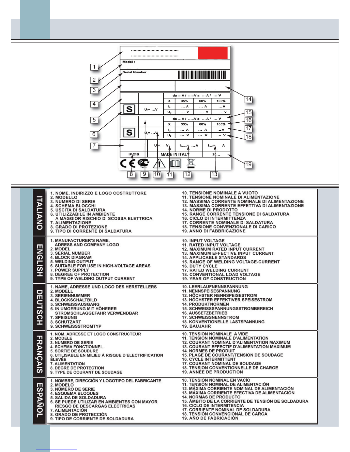
TARGA DATI, NOMINAL DATA, LEISTUNGSCHILDER,
PLAQUE DONÉES, PLACA DE CARACTERÌSTICAS
Page 5
1
ESPAÑOL FRANÇAIS
DEUTSCH
ENGLISH
ITALIANO
• AVVERTENZE .................................................................................. pag. 2, 3, 4
1. CARATTERISTICHE GENERALI E NOTE PER LA CONSULTAZIONE
DEL MANUALE............................................................................................ pag. 5
2. DESCRIZIONE DELL’APPARATO.................................................................... pag. 5
3. CARICAMENTO DEL FILO DI SALDATURA..................................................... pag. 8
4. SALDATURA MIG/MAG................................................................................. pag. 9
4. 1 SALDATURA MIG Short Arc Manuale........................................................... pag. 10
4. 2 SALDATURA MIG Short Arc Sinergico......................................................... pag. 11
4. 3 SALDATURA MIG Arco Pulsato Sinergico.................................................... pag. 14
5. COLLEGAMENTO PER SALDATURA MIG...................................................... pag. 16
5.1 TORCIA MIG................................................................................................. pag. 16
5. 2 COLLEGAMENTO PER SALDATURA MIG con torcia tradizionale...................... pag. 16
5. 3 COLLEGAMENTO PER SALDATURA MIG con torcia Push-Pull..................................... pag. 16
6. INNESCO DELL’ARCO MIG............................................................................ pag. 17
7. REGOLAZIONE DELLA SALDATRICE............................................................. pag. 17
8. COME OTTENERE I MIGLIORI RISULTATI DI SALDATURA............................... pag. 17
9. SALDATURA MMA........................................................................................ pag. 18
9. 1 SALDATURA MMA Manuale........................................................................... pag. 18
10 TABELLA DI SALDATURA ............................................................................. pag. 19
11 COLLEGAMENTO PER SALDATURA MMA..................................................... pag. 19
12. INNESCO DELL’ARCO MMA.......................................................................... pag. 19
13. SALDATURA TIG........................................................................................... pag. 20
13. 1 SALDATURA TIG (Lift-Arc)............................................................................. pag. 21
14. COLLEGAMENTO PER SALDATURA TIG........................................................ pag. 23
15. COLLEGAMENTO DELL’ALIMENTAZIONE...................................................... pag. 23
16. COLLEGAMENTO REMOTO........................................................................... pag. 23
16.1 COLLEGAMENTO REMOTO CORRENTE DI SALDATURA................................ pag. 24
17. COLLEGAMENTO DELLE USCITE.................................................................. pag. 24
18. COLLEGAMENTO DELLA BOMBOLA E DEL REGOLATORE DEL GAS......................... pag. 24
19. MANUTENZIONE ORDINARIA DELLA MACCHINA........................................... pag. 24
20. SOSTITUZIONE DELLA GUAINA GUIDAFILO DELLA TORCIA.......................... pag. 25
21. MEMORIZZAZIONE DEL PUNTO DI LAVORO.................................................. pag. 26
22. BLOCCO DEL PUNTO DI LAVORO................................................................. pag. 26
23. CODICE ERRORI........................................................................................... pag. 29
24. RICERCA GUASTI......................................................................................... pag. 30
25. SCHEMA BLOCCHI ...................................................................................... pag. 31
26. PARTI DI RICAMBIO...................................................................................... pag. 32
Page 6
2
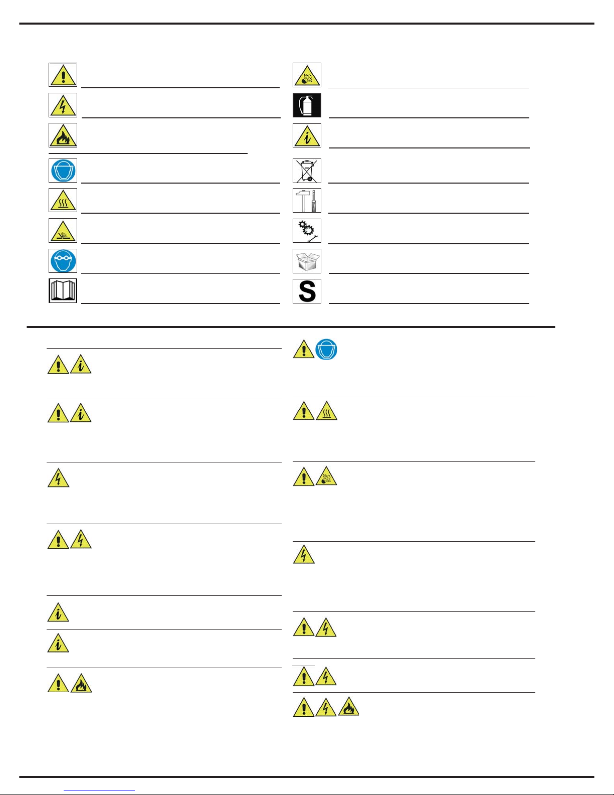
SIMBOLI UTILIZZATI
SIMBOLI UTILIZZATI
AVVERTENZE
AVVERTENZE
Situazione che può causare gravi danni alle persone e/o
alla apparecchiatura
PERICOLO
DI SVILUPPO FIAMMA
Indica che è necessario indossare la visiera protettiva per evitare scottature e danni agli occhi
GAS TOSSICI
Indica il pericolo, in condizioni anomale, di sviluppo di gas tossici
PERICOLO SCORIE
Indica la possibilità di venir scottati da scorie bollenti
Indica la necessità di indossare occhiali protettivi per
evitare danni dovuti a scorie proiettate
PERICOLO DI FULMINAZIONE
Grave pericolo di fulminazione per le persone
Indica il pericolo di ferimento o di morte dovuto a trascuratezza durante l’utilizzo o manutenzione di bombole o valvole per gas compresso
Informazione importante da tenere in debito conto. Indica le precauzioni da tenere in conto per una migliore
installazione ed utilizzo.
INFORMAZIONI
RELATIVE ALLO SMALTIMENTO
ISTRUZIONI
D’INSTALLAZIONE
ISTRUZIONI
D’USO
ISTRUZIONI
DI DISIMBALLAGGIO
PRECAUZIONI PER
L’ESTINZIONE DELL’INCENDIO
Leggere il manuale d’istruzioni
UTILIZZABILE IN AMBIENTE A MAGGIOR RISCHIO
DI SCOSSA ELETTRICA
RIGUARDO ALLA SICUREZZA DELL’APPARATO
Questo apparato è un prodotto previsto solamente per uso
industriale e professionale e, come tale, deve essere uti-
lizzato solamente da specialisti o da persone addestrate.
È compito dell’utilizzatore fare in modo che l’apparato non sia accessibile a personale non professionale.
Fimer SpA declina ogni responsabilità per danni a persone o
cose derivanti da un uso inesperto, improprio o disattento delle proprie apparecchiature.
L’utilizzatore deve avere cura del proprio strumento
di lavoro! si rammenta esplicitamente che un utensi-
le o un apparato può diventare pericoloso se non è
integro. Anche apparati ed accessori deteriorati o guasti possono
essere pericolosi: in caso di funzionamento anomalo o di surriscaldamento disconnettere immediatamente l’intero apparato dalla rete elettrica e renderlo al fornitore per l’opportuna riparazione.
Leggere il presente manuale prima di utilizzare il vostro sistema
di saldatura, questo vi aiuterà ad effettuare un lavoro migliore e in
condizioni di maggiore sicurezza.
Tramite la lettura del manuale conoscerete più a fondo le possibilità, le
limitazioni e i potenziali pericoli del lavoro di saldatura.
Conservate il presente manuale per tutta la vita dell’apparato e riponetelo in un luogo facilmente accessibile all’addetto all’utilizzo della macchina.
Le informazioni sulla sicurezza che troverete nel seguito devono essere considerate come una guida per la vostra incolumità, ma non possono comunque sostituirsi completamente
alla competenza e al corretto comportamento dell’utente.
Tutti gli apparati connessi alla rete elettrica possono risultare pericolosi se le istruzioni relative all’utilizzo sicuro del-
l’apparato non sono conosciute o non sono seguite. Di
conseguenza per ridurre il rischio di morte o di gravi danni dovuti a scossa elettrica occorre leggere, capire e seguire queste avvertenze sulla
sicurezza. Prestate la massima attenzione al fatto che anche eventuali
persone che assistono alle operazioni di saldatura devono essere opportunamente istruite sui pericoli relativi all’attività in corso.
Il fuoco e le esplosioni possono provocare seri danni a per-
sone e cose! Per ridurre il rischio di morte o di gravi danni
dovuti al fuoco o ad esplosioni occorre leggere, capire e seguire queste avvertenze sulla sicurezza. Prestate la massima attenzione al fatto che anche eventuali persone che assistono alle operazioni di saldatura
devono essere opportunamente istruite sui pericoli relativi all’attività in corso. Ricordate sempre che l’operazione di saldatura, per sua stessa natura,
produce scintille, spruzzi di materiale bollente, gocce di metallo fuso, scorie
e schegge bollenti che possono provocare incendi, bruciare la pelle e danneggiare gravemente gli occhi.
I raggi emessi dall’arco elettrico possono danneggiare gli occhi
e bruciare la pelle! Per ridurre il rischio di danni dovuti ai rag-
gi emessi dall’arco occorre leggere, capire e seguire queste
avvertenze sulla sicurezza. Prestate la massima attenzione al fatto che anche
eventuali persone che assistono alle operazioni di saldatura devono essere
opportunamente istruite sui pericoli relativi all’attività in corso. Indossare e far
indossare alle persone presenti la maschera protettiva
.
I FUMI, I GAS E I VAPORI POSSONO DETERMINARE
DANNI!
Per ridurre il rischio di danni dovuti ai fumi di saldatura
occorre leggere, capire e seguire queste avvertenze sulla sicurezza.
Prestate la massima attenzione al fatto che anche eventuali persone
che assistono alle operazioni di saldatura devono essere opportunamente istruite sui pericoli relativi all’attività in corso.
L
a trascuratezza durante l’utilizzo o la manutenzione di
bombole o valvole per gas compresso può determinare il
ferimento o la morte dell’utente o delle persone circostanti!
Per ridurre il rischio di danni dovuti ai gas compressi occorre leggere,
capire e seguire queste avvertenze sulla sicurezza. Prestate la massima attenzione al fatto che anche eventuali persone che assistono alle
operazioni di saldatura devono essere opportunamente istruite sui pericoli relativi all’attività in corso.
TENSIONI PERICOLOSE
L’apparato contiene al suo interno tensioni potenzialmente letali.
Tutte le tensioni pericolose all’interno dell’apparato sono segregate in apposite zone accessibili solamente utilizzando attrezzi non
forniti in dotazione con la saldatrice.
Tutte le operazioni di manutenzione o riparazione che richiedono
l’accesso a queste parti dell’apparato possono essere effettuate solamente da personale tecnico appositamente istruito dalla Fimer S.p.A.
INTRODUZIONE OGGETTI
Non introdurre oggetti nelle feritoie di aerazione ed evi-
tare il contatto con qualsiasi tipo di sostanza liquida;
provvedere alla pulizia solamente con panno asciutto. Tali attenzioni
devono essere osservate anche a macchina spenta.
SEZIONE DEI CAVI
Verificare che i cavi dell’impianto siano di sezione ade-
guata alla corrente di ingresso della saldatrice. Estendere il controllo ad eventuali prolunghe. Si raccomanda che il cavo della prolunga sia sempre completamente steso: un cavo arrotolato può surriscaldarsi e divenire pericoloso, inoltre un cavo avvolto a matassa o arrotolato sul
proprio rocchetto può determinare grossi malfunzionamenti nella saldatrice.
CALPESTABILITÀ
La parte superiore delle saldatrici non sono progettati per
reggere pesi consistenti. Non salire mai sull’apparto.
SIMBOLI UTILIZZATI
Page 7
3
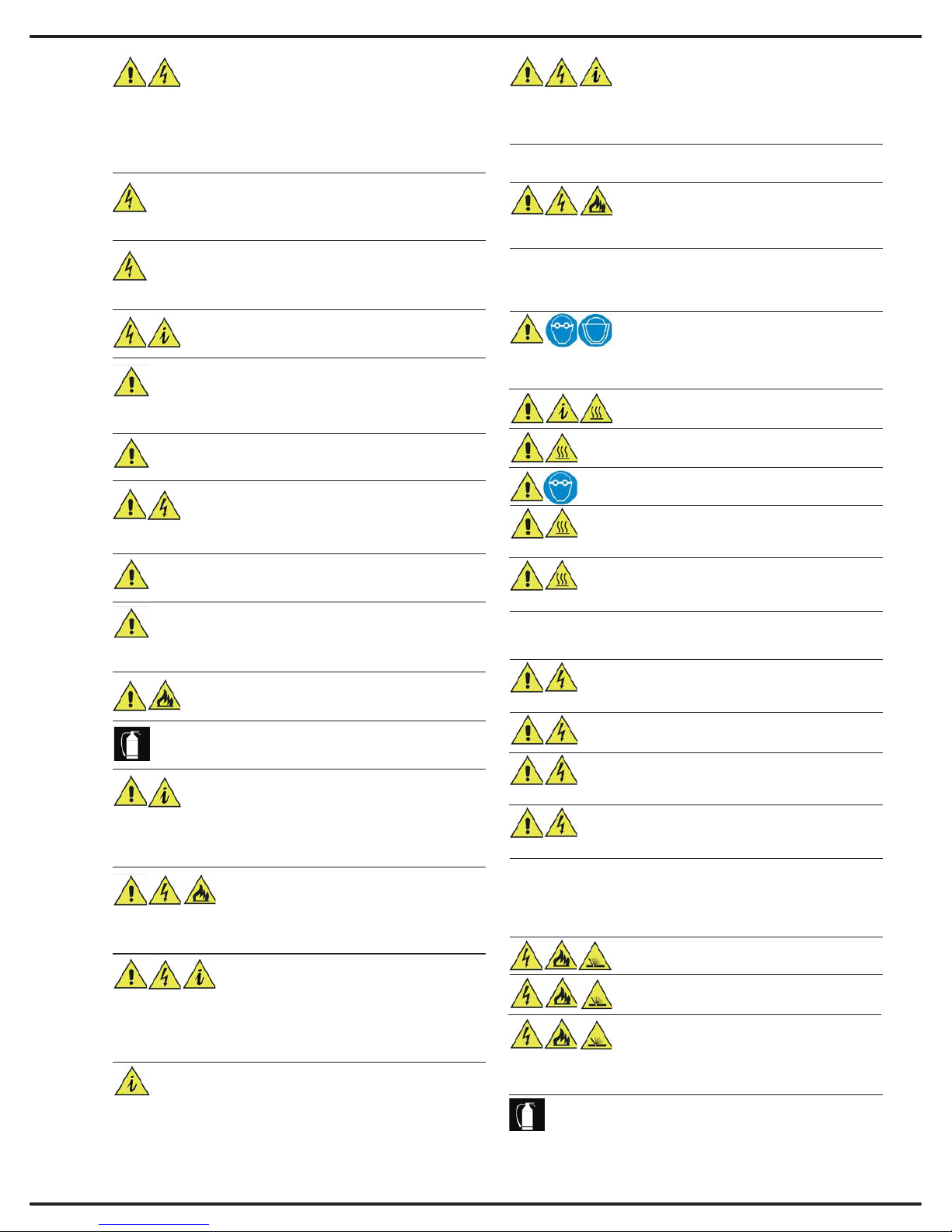
AVVERTENZE RELATIVE ALLA SICUREZZA
AVVERTENZE RELATIVE ALLA SICUREZZA
DEL PROCESSO DI SALDATURA
DEL PROCESSO DI SALDATURA
PROTEZIONE DEL PERSONALE
PROTEZIONE DEL PERSONALE
POSIZIONAMENTO
Posizionare lontano da fonti di calore.Posizionare in locali aven-
ti una sufficiente aerazione. Posizionare in locali ben riparati: non
è possibile installarla all’aperto. Non posizionare in locali molto polverosi: la polvere può entrare all’interno dell’apparato impedendone il corretto raffreddamento. La saldatrice deve essere posizionata su una superficie di sostegno
piana e stabile che si estende oltre la base del prodotto in tutte le direzioni.
PULIZIA DEL LUOGO DI UTILIZZO
Il luogo dove è utilizzata la saldatrice deve esse-
re mantenuto pulito e asciutto per evitare che
qualsiasi oggetto o liquido possa essere aspirato all’interno dell’apparato. Tale circostanza può portare, oltre che al malfunzionamento dell’apparato, ad un concreto pericolo di incendio.
RIPARAZIONE
Non tentare mai di riparare il prodotto da soli, ma
rivolgersi sempre al costruttore o ad un suo centro
di assistenza autorizzato. Qualsiasi tentativo di riparazione non autorizzato per iscritto e non gestito direttamente dal costruttore oltre ad
essere oggettivamente pericoloso, determina l’immediata scadenza della garanzia e la cessazione di qualsiasi responsabilità per eventuali malfunzionamenti e per le conseguenze che da essi possono derivare.
ACCESSORI
Usare solo accessori previsti dal costruttore, l’uti-
lizzo di accessori di tipo differente può determinare gravi malfunzionamenti dell’apparato. L’utilizzo di accessori non originali determina l’immediata scadenza della garanzia e la cessazione
di qualsiasi responsabilità per eventuali malfunzionamenti e per le conseguenze che da essi possono derivare.
ATTENZIONE!
Il processo di saldatura, se non si rispettano atten-
tamente le istruzioni relative alla sicurezza e all’uso, può essere pericoloso non solo per l’operatore, ma anche per le
persone vicine al luogo in cui avviene la saldatura.
PAVIMENTO DELL’AREA DI LAVORO
Il pavimento dell’area di lavoro DEVE essere
realizzato in materiale ininfiammabile.
PIANO DELL’AREA DI LAVORO
Il piano del tavolo da lavoro su cui si effettua la saldatu-
re DEVE essere realizzato in materiale ininfiammabile.
PROTEZIONE DEI MURI E DEI PAVIMENTI
I muri circostanti l’area di saldatura e i pavimenti
devono essere protetti da schermi realizzati in materiale ininfiammabile; questo, non solo per ridurre il rischio di incendio,
ma anche per fornire una protezione atta ad evitare che i muri e/o il
pavimento siano danneggiati durante le operazioni di saldatura.
ESTINTORE
Posizionare nell’area di lavoro un estintore omologato di
tipo e dimensioni appropriate. Verificarne periodicamente
lo stato (effettuare la manutenzione prog1rammata) e assicurarsi
che il personale si opportunamente istruito per il suo utilizzo
MASCHERA DI PROTEZIONE
Indossare una maschera di protezione per sal-
datura non infiammabile per proteggersi il collo,
la faccia e i lati della testa. Mantenete il vetro protettivo pulito e sostituirlo se è rotto o crepato. Posizionare un vetro di protezione trasparente tra lo schermo della maschera e la zona di saldatura.
ABBIGLIAMENTO
Indossare un abbigliamento di protezione non ecces-
sivamente largo, chiuso, ininfiammabile e senza tasche.
Posizionare sempre nelle immediate vicinanze dell’area di
lavoro un estintore di tipo omologato.Effettuare sempre le
revisioni periodiche all’estintore.
PERICOLO PER GLI OCCHI
Non guardare MAI l’arco senza le opportune protezioni.
FUMI E GAS 1
Pulire bene la parte da saldare da vernici, ruggine o qualsiasi sporcizia per evitare l’emissione di fumi pericolosi
di composizione non conosciuta.
FUMI E GAS 2
Non saldare MAI metalli contenenti zinco, mercurio, cromo,
grafite, metalli pesanti, cadmio o berillio senza che l’operato-
re e le persone presenti durante la saldatura indossino appositi respiratori.
SPAZI RISTRETTI
Quando si lavora in spazi ristretti occorre lasciare la sorgente di potenza al di fuori della zona in cui avviene la
saldatura e fissare il cavo di terra al pezzo da lavorare.
AREE UMIDE
Non effettuare mai l’operazione di saldatura in
ambienti umidi o bagnati.
CAVI DANNEGGIATI 1
Non utilizzare mai cavi danneggiati (tale precauzione deve essere rispettata sia per i cavi di rete
che per quelli di saldatura)
CAVI DANNEGGIATI 2
Non rimuovere mai i pannelli della saldatrice. Nel caso
in cui la saldatrice sia dotata di pannelli apribili veri-
ficare sempre che, al momento dell’uso, siano ben chiusi.
PROTEZIONE DALLE SCOSSE ELETTRICHE
PROTEZIONE DALLE SCOSSE ELETTRICHE
Oltre alle avvertenze generali precedentemente riportate occorre rispettare scrupolosamente anche le seguenti precauzioni.
PREVENZIONE DEGLI INCENDI
PREVENZIONE DEGLI INCENDI
Oltre alle avvertenze generali precedentemente riportate occorre rispettare scrupolosamente anche le seguenti precauzioni. Il
processo di saldatura richiede il raggiungimento di temperature
elevate, di conseguenza esiste un concreto rischio di incendio.
ASSISTENZA
La saldatrice dovrà esser consegnata al centro di assistenza
quando l’apparato è stata in qualche modo danneggiato, come
nei casi in cui vi sia penetrato del liquido, vi siano caduti sopra o dentro
oggetti, quando sia stato esposto alla pioggia o all’umidità (al di fuori dei
valori specificati), quando non funziona normalmente, quando presenta
evidenti cambiamenti di prestazione o quando è stato fatto
cadere.
INTERRUTTORE DI PROTEZIONE
Verificare che l’impianto che alimenta la saldatrice sia
dotato di opportuno organo di sezionamento e protezione. L’interruttore deve aprire tutti i cavi di alimentazione (Nel
caso di linea monofase: Fase e neutro; nel caso di linea trifase:
tutte e tre le fasi; nel caso di linea a quattro cavi: tutte le fasi e il
conduttore di neutro). Si consiglia l’uso di fusibili ritardati o di interruttori magnetotermici con curva K.
COLORAZIONE DEI CAVI
Il cavo di collegamento giallo-verde serve per la connessio-
ne della terra di protezione (non utilizzarlo per altri scopi!)
AMBIENTE DI UTILIZZO E/O INSTALLAZIONE1
Apparato non adatto a locali da bagno, docce, piscine o aree
similari. Nel caso sia necessario operare in tali ambienti verificare preventivamente il serraggio di tutti i rubinetti di adduzione dell’acqua
e verificare che nessuno stia utilizzando l’ambiente per la propria funzione.
AMBIENTE DI UTILIZZO E/O DI INSTALLAZIONE 4
Non utilizzare la saldatrice in ambienti in cui sia presente
una atmosfera esplosiva o corrosiva o abrasiva o salina.
VENTILAZIONE DEL LOCALE
Saldare in un locale ben ventilato senza accesso diretto
ad altri luoghi di lavoro
CONNESSIONE DI TERRA
Nel caso che la saldatrice non sia fornita della spina di alimentazione, connettere sempre per primo il cavo di terra. In caso
di scollegamento dell’apparato scollegare il cavo di terra per ultimo.
SPINA E PRESA DI COLLEGAMENTO
Nel caso che la saldatrice sia fornita di spina di collegamento alla
rete verificare sempre con attenzione che sia conforme al tipo di
presa montata a parete. Non manomettere mai il cavo di collegamento.
MOVIMENTAZIONE 1
Alcune tipologie di saldatrici sono apparati pesanti, effettuare le ope-
razioni di movimentazione con attenzione. Nel caso la saldatrice sia
utilizzata, anche momentaneamente, in ambienti civili controllare sempre
preventivamente la tenuta delle solette e dei pavimenti “sopraelevati”.
AMBIENTE DI UTILIZZO E/O INSTALLAZIONE 2
La saldatrice non è idonea al funzionamento e immagazi-
namento sotto pioggia o neve
AMBIENTE DI UTILIZZO E/O INSTALLAZIONE 3
La saldatrice non è prevista per essere installata o utilizzata in
luoghi soggetti ad urti o vibrazioni; ad esempio: mezzi di trasporto
su strada, su rotaia, su fune, aerei, navali ed equiparabili (come gru, carri ponte, parti di macchine utensili soggette a movimento o vibrazione)
MOVIMENTAZIONE 2
Non conservare o trasportare la saldatrice inclinata o
appoggiato su un lato.
Oltre alle avvertenze generali precedentemente riportate occorre rispettare scrupolosamente anche le seguenti precauzioni
Page 8
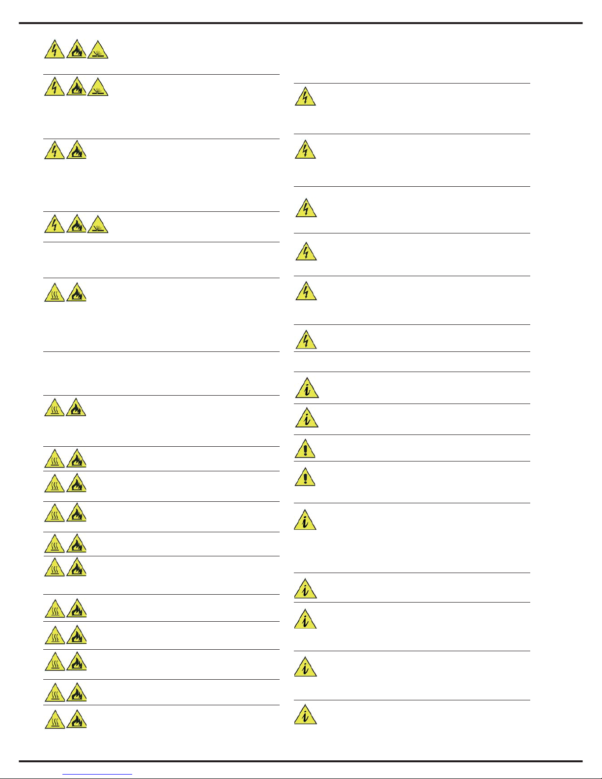
PULIZIA DELL’AREA CIRCOSTANTE ALLA
ZONA DI LAVORO
Ripulire accuratamente la zona di lavoro da qualsiasi materiale combustibile.
GRAVISSIMO PERICOLO! 1
Non effettuare assolutamente MAI le operazioni di sal-
datura in un ambiente ristretto (per esempio un container, una cisterna, un ripostiglio) che abbia contenuto o contenga materiali o
liquidi tossici, infiammabili o esplosivi. Prestare la massima attenzione al fatto che soprattutto le cisterne possono conservare al loro interno gas e vapori tossici, infiammabili o esplosivi anche dopo anni dal loro svuotamento.
GRAVISSIMO PERICOLO! 3
Attenzione non utilizzare mai le apparecchiature
per saldatura per sgelare i tubi dell’acqua
GRAVISSIMO PERICOLO! 2
Non effettuare assolutamente MAI le operazioni di salda-
tura su un serbatoio che abbia contenuto o contenga materiali o liquidi tossici, infiammabili o esplosivi. Prestare la massima attenzione al fatto che i serbatoi possono conservare al loro interno vapori
infiammabili ed esplosivi anche dopo anni dal loro svuotamento. Nel
caso sia necessario effettuare saldature su di un serbatoio occorre SEMPRE passivarlo riempiendolo di sabbia o equivalente materiale inerte.
VENTILAZIONE DEL LOCALE DOVE AVVIENE LA
SALDATURA.
Ventilare il locale dove avviene la saldatura adeguata-
mente. Mantenere un sufficiente flusso d’aria per evitare l’accumulo di gas tossici o esplosivi. L’operazione di saldatura effettuata su
certi tipi o combinazioni di materiali può generare fumi tossici. In questi casi utilizzare appropriati sistemi di respirazione. PRIMA di iniziare
a saldare leggere e capire le prescrizioni di sicurezza della lega di saldatura.
TIPI DI GAS DA UTILIZZARE
Queste saldatrici devono essere impiegate solamente con
gas inerti (non infiammabili) per la protezione dell’arco di saldatura.
Ovviamente è della massima importanza scegliere il tipo di gas appropriato per la saldatura che deve essere eseguita.
BOMBOLE NON MARCATE
Non usare MAI gas da bombole prive della propria etichetta.
RIDUTTORE DI PRESSIONE 1
Non collegare MAI la bombola direttamente alla salda-
trice. Utilizzare sempre un riduttore di pressione.
RIDUTTORE DI PRESSIONE 2
Assicurarsi che il regolatore di pressione funzioni correttamente.
Leggere con attenzione le istruzioni del regolatore di pressione.
RIDUTTORE DI PRESSIONE 3
Non lubrificate mai alcuna parte del riduttore di pressione
RIDUTTORE DI PRESSIONE 4
Ciascun regolatore è progettato per essere utilizzato con
uno specifico tipo di gas. Assicurarsi che il riduttore sia
del tipo indicato per il gas di protezione in uso.
VENTILAZIONE
VENTILAZIONE
Oltre alle avvertenze generali precedentemente riportate occorre rispettare scrupolosamente anche le seguenti precauzioni.
GAS DI PROTEZIONE ALLA SALDATURA
GAS DI PROTEZIONE ALLA SALDATURA
Nel caso si utilizzino processi di saldatura utilizzanti gas di protezione, oltre alle avvertenze generali precedentemente riportate
occorre rispettare scrupolosamente anche le seguenti precauzioni.
BOMBOLE DANNEGGIATE
Non usare MAI bombole danneggiate o deteriorate.
MOVIMENTAZIONE DELLE BOMBOLE
Non spostare MAI la bombola prendendola per la valvola
BOMBOLE
Non esporre le bombole ad un calore eccessivo, a
scintille, a scorie o alla fiamma.
TUBO DEL GAS 1
Assicurarsi che il tubo del gas sia in buono stato
TUBO DEL GAS 2
Mantenere sempre il tubo del gas lontano dal
punto di saldatura
SCARICHE ELETTRICHE
SCARICHE ELETTRICHE
Per ridurre il rischio di seri danni dovuti alle scariche elettriche,
oltre alle avvertenze generali precedentemente riportate occorre rispettare scrupolosamente anche le seguenti precauzioni.
INFORTUNIO DOVUTO A SCARICA ELETTRICA
Nel caso in cui una persona sia colpita da scarica elettrica NON
prestarle soccorso se è ancora in contatto coi cavi. Togliere immediatamente tensione e POI soccorrerla.
CONTATTO COI CAVI
Non fare manovre sui cavi di ingresso se l’alimentazione non
è stata interrotta.
Non toccare il circuito di saldatura: anche se normalmente la tensione del circuito di saldatura non è molto elevata, è comunque buona
norma prudenziale non toccare mai gli elttrodi di saldatura.
STATO DI CONSERVAZIONE DEI CAVI E DELLA PRESA
Verificare spesso l’integrità del cavo di alimentazione e del-
la relativa spina e presa. Ciò è particolarmente necessario
nelle apparecchiature che subiscono ripetuti movimenti.
RIPARAZIONI
Non tentare mai di effettuare in proprio delle riparazioni sul-
la saldatrice; questo determina non solo l’immediata deca-
denza della garanzia, ma può essere fonte di seri pericoli.
APERTURA DELLE ZONE ACCESSIBILI ALL’OPERATORE
Verificare sempre che la saldatrice sia disconnessa dalla rete
prima di effettuare le manovre di ordinaria manutenzione
riportate in questo manuale (ad esempio la sostituzione di un elettrodo consumato, del filo di saldatura, il cambio del trainafilo ecc)
Non puntare mai la pistola di saldatura o l’elettrodo verso se
stessi o verso le persone presenti
Assicurarsi che vicino alla saldatrice non passino cavi di controllo,
telefonici e bus di segnale (come reti di computer, bus di campo ecc)
Assicurarsi che vicino alla saldatrice non vi siano telefoni,
televisori, computer o altri apparati di controllo.
COMPATIBILITA’ ELETTROMAGNETICA
Assicurarsi che vicino alla saldatrice non vi siano persone
portatrici di pace-macker.
Non utilizzare la saldatrice in ambiente ospedaliero o in ambulatori (sia medici che veterinari). Prestare particolare attenzione al fatto che nelle immediate vicinanze della zona di saldatu-
ra non vi siano apparecchi elettromedicali in funzione.
Nel caso in cui la saldatrice provochi disturbi ad altre apparecchiature
si può cercare di diminuirne l’effetto tramite le seguenti precauzioni
1. Verificare che tutti gli sportelli eventualmente presenti nella saldatrice siano ben chiusi
2. Accorciare i cavi di alimentazione
3. Interporre dei filtri EMC tra la saldatrice e la linea di alimentazione
Classificazione per compatibilità elettromagnetica: CISPR
11, gruppo2, classe A.
Questo è un apparato in Classe A e non è adatto a funzionare in ambienti residenziali in cui la potenza elettrica è fornita
tramite rete pubblica in bassa tensione. In questi ambienti
potrebbero sorgere problemi per garantire la compatibilità elettromagnetica, sia per quanto riguarda i disturbi condotti che irradiati.
Questa apparecchiatura non è conforme con la IEC 61000-
3-12.Se viene collegata ad una rete pubblica in bassa ten-
sione, è responsabilità dell’installatore o dell’utilizzatore
assicurarsi, contattando, se necessario, il gestore della rete, che
l’apparato possa essere connesso.
Questa apparecchiatura è adatta ad essere utilizzata in ambien-
te industriale con rete protetta da interruttore differenziale ritar-
dato all’intervento, di tipo B e con corrente di intervento >200mA
4
Page 9
5
ESPAÑOL FRANÇAIS
DEUTSCH
ENGLISH
ITALIANO
1. CARATTERISTICHE GENERALI E
NOTE PER LA CONSULTAZIONE DEL
MANUALE
Le saldatrici tipo “TM236 EVO” sono
apparecchiature realizzate con tecnologia
INVERTER; si tratta di apparati
estremamente compatti e versatili utilizzabili
in tutte le situazioni in cui, il minimo
ingombro, si deve coniugare con le più
elevate prestazioni.
Queste saldatrici permettono di effettuare
saldature in tecnologia MMA, TIG e
MIG/MAG manuale o sinergica (short arc,
pulsata o doppio pulsata).
L’innovativo sistema di interfacciamento con
l’operatore tramite l’ampio display TFT a
colori di 5,7’’ consente un utilizzo
dell’apparato semplice ed intuitivo, senza
rinunciare alla possibilità di personalizzare
tutti i parametri di saldatura.
Tutti i principali parametri della macchina
sono memorizzati in un’apposita scheda di
memoria (SD-Card); in questo modo sarà
sempre possibile mantenere il vostro
apparato aggiornato ai più recenti sviluppi
nell’ambito della saldatura.
L’estrazione della scheda di memoria
impedisce il funzionamento dell’apparato,
costituendo così un valido sistema di
antifurto e di sicurezza contro gli usi impropri.
Grazie alle avanzate tecniche di controllo
adottate, il prodotto ha un’elevatissima
affidabilità e facilità d’uso.
Questo manuale di istruzione riporta nel
dettaglio le regolazioni e le modalità di
funzionamento della macchina: la sua lettura
completa vi permetterà di apprezzarne
l’estrema flessibilità e la praticità di utilizzo.
Attenzione: l'apparecchio può essere
utilizzato solo per gli impieghi descritti nel
manuale e non deve essere utilizzato per
altri fini impropri.
2. DESCRIZIONE DELL’APPARATO
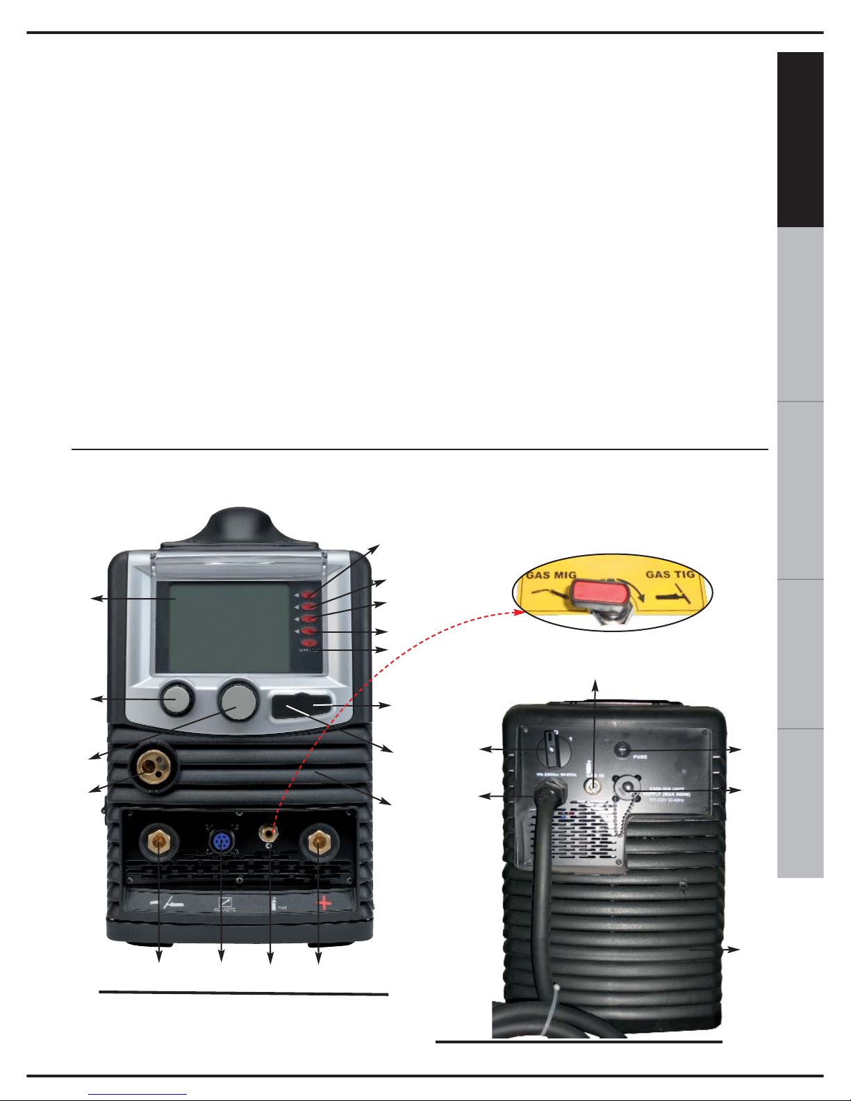
Fig. 1
11
20
Fig. 2
17
19
18
1
2
3
4
5
6
10
9
16
12
14
15
13
11
7
8
R
U
B
I
N
E
T
T
O
I
N
T
E
R
N
O
21
tramite questo selettore è
possibile scegliere l’uscita
del gas dedicata per ogni
processo di saldatura
Page 10
6
FIGURA 1:
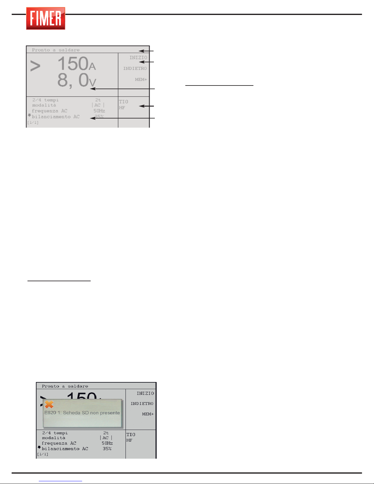
1. Display Grafico:
Il display a colori da 5,7’’ visualizza differenti
schermate a secondo che sia in modalità di
saldatura o in modalità di settaggio.
In modalità saldatura il display è diviso in 5
zone principali:
Parte 1: Stato della macchina
Parte 2: Significato dei pulsanti attivi
(pulsanti 2, 3, 4, 5, 6 di fig.1)
Parte 3: Valore delle grandezze impostate
Parte 4: Tipo di processo selezionato
Parte 5: Indica i valori impostabili per i vari
parametri di saldatura (per variare il valore
impostato evidenziarlo tramite la manopola 10
e confermare la scelta premendo la manopola
stessa; il valore viene evidenziato in
contrasto. Ruotando la manopola si varia il
valore, per confermare il nuovo valore occorre
premere nuovamente la manopola 10).
Valore evidenziato:
Indica il parametro che
viene variato tramite la manopola 10.
VISUALIZZAZIONI:
- All’accensione viene visualizzato il logo
Fimer e la revisione del Firmware caricata.
PULSANTI DI COMANDO:
(2, 3, 4, 5,6 di fig.1)
Ad ogni pulsante di comando è associata una
specifica funzione visualizzata sul display.
7.Alloggiamento SD: questo alloggiamento,
coperto da un apposito tappo in gomma,
contiene la SD-Card fornita in dotazione con
la macchina; senza di essa la macchina
rimane inattiva ed un’ apposita segnalazione
viene riportata sul display.
8. Porta USB: solo per assistenza tecnica.
9. Manopola di impostazione del parametro
principale di saldatura: tramite questa
manopola si imposta il parametro principale di
saldatura:
Saldatura MMA/TIG:
imposta la corrente di
saldatura.
11. Griglie di aerazione (non devono mai
essere ostruite).
12. Presa dinse frontale “-”: presa polo
negativo. Presa di collegamento della torcia
in modalità TIG.
Modalità MMA: Pinza di massa
Modalità MIG: Pinza di massa
13. Connettore per controllo remoto.
14. Presa dinse frontale “+”: presa polo
positivo.
Modalità MMA: Pinza porta elettrodo
Modalità TIG: Pinza di massa
Modalità MIG con gas: Non usato
15. Uscita Gas:
Modalità MMA: inattiva
Modalità TIG: connessione gas alla torcia di
saldatura (rubinetto interno in posizione GAS TIG)
Modalità MIG con gas: inattiva (rubinetto
interno in posizione GAS MIG)
16. ATTACCO RAPIDO TORCIA Attacco in
uscita (positivo), per il connettore (tipo euro)
della torcia di saldatura permette i contatti
elettrici e per il gas.
FIGURA 2:
17. Interruttore ON-OFF: accende e
spegne la macchina.
18. Cavo di ingresso: Cavo di
collegamento alla rete elettrica.
19. Ingresso gas di saldatura:
Modalità MMA: non usato
Modalità TIG: connessione gas alla bombola
Modalità MIG con gas: connessione gas alla
bombola
20. Fusibile
21.CONNETTORE PER L’ALIMENTAZIONE
DEL SISTEMA DI RAFFREDDAMENTO A
LIQUIDO (Opzione): Attenzione il
connettore presenta al suo interno tensioni
pericolose: non utilizzarlo MAI per funzione
diversa da quella specificata.
Parte 1
Parte 2
Parte 3
Parte 4
Parte 5
Page 11
ITALIANO
ENGLISH
DEUTSCH
FRANÇAISESPAÑOL
7
22
23
24
26
25
27
28
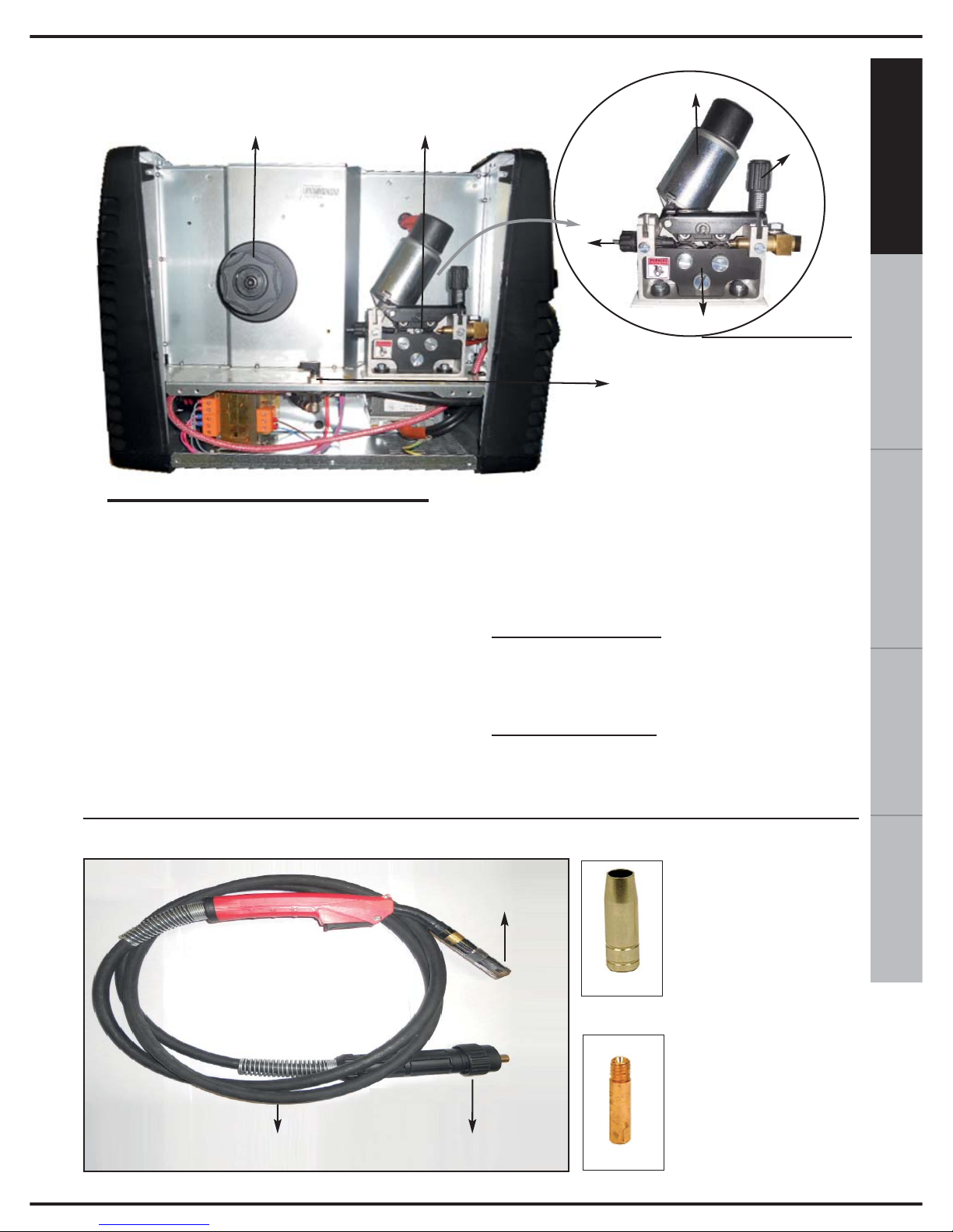
FIGURA 3:
22. SUPPORTO PER BOBINA FILO
la bobina di filo da 300mm necessita di un
supporto esterno (cod. 580.727.001)
23. GRUPPO TRAINAFILO: evidenziato
con maggior dettaglio in figura 3A.
24. MOTORE TRAINAFILO
25. REGOLATORE PRESSIONE FILO:
Permette di regolare la tensione del filo di
saldatura.
26. INGRESSO FILO DEL MOTORINO
TRAINAFILO
27. RULLINI TRAINAFILO
28. RUBINETTO DEL GAS: Il rubinetto del
gas presenta tre posizioni
Posizione GAS MIG:
invia il gas di saldatura,
proveniente dalla connessione 19 della
bombola, all’Euroconnettore (Utilizzare questa
posizione per la saldatura MIG con gas)
P
osizione GAS TIG: invia il gas di saldatura,
proveniente dalla connessione 19 della bombola,
alla presa 14 posta sul frontale (Utilizzare questa
posizione per la saldatura TIG)
Fig. 3
Fig. 3A
TORCIA DI SALDATURA
Fig.4A
Fig.4B
UGELLO
DIFFUSORE GAS
PUNTA
GUIDAFILO
CORPO TORCIA
CAVO
EUROCONNETTORE
Fig.4
Page 12
8
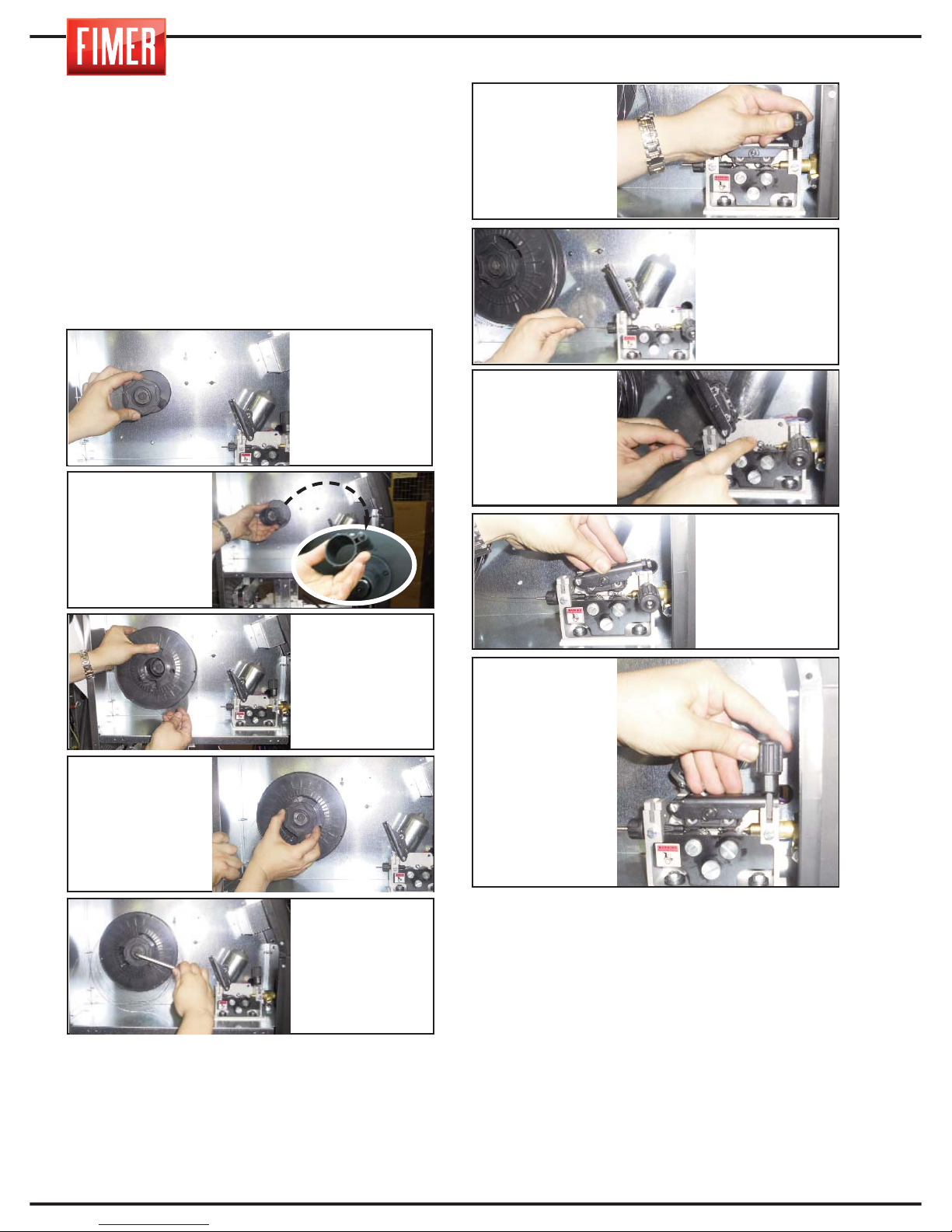
3. CARICAMENTO DEL FILO DI
SALDATURA
Per caricare il filo di saldatura seguire queste
istruzioni e fare riferimento alla sequenza sotto
riportata.
Attenzione: prima di effettuare le operazioni
per l’istallazione del filo rimuovere sempre l’ugello
diffusore del gas (Fig. 4A) e la punta guidafilo (Fig.
4B) dalla torcia di saldatura.
1. scollegare il cavo di alimentazione di rete
(18 di Fig. 2)
N.B. Quando si effettua un cambio di diametro del filo biso-
gna assicurarsi che la cava corretta del rullino trainafilo sia
rivolta verso l’interno della macchina. Per far questo verificare che sia leggibile (rivolto verso l’esterno della macchina) il valore corrispondente al diametro e al tipo di filo
utilizzato. Si ricorda che i rullini dotati di cava a “V” sono
adatti al trascinamento di fili tipo ferro e acciaio. I rullini con
cava ad “U” sono adatti a fili tipo alluminio.
Attenzione: prima di procedere ai passi successivi verificare che il cavo della torcia (Fig. 4) sia ben teso e che il filo
di saldatura non presenti angoli o sbavature. Se non si
segue questa precauzione si potrebbe danneggiare la
guaina guidafilo interna alla torcia.
Una volta fatto scorrere il filo attraverso la torcia, serrare
nuovamente la punta guidafilo e l’ugello/diffusore del gas.
Avvitare la brugola in modo da ottenere la frizione ottimale: se si stringe troppo si rischia una
frizione eccessiva che tende a bloccare il regolare svolgimento della bobina. Al contrario una
frenatura troppo scarsa fa sì che il filo al termine della saldatura si srotoli accidentalmente.
2. Svitare il
pomello zigrinato
posto al centro
del supporto
della bobina del
filo di saldatura
(22 di Fig. 3).
7. Inserire il filo
nel tubetto di
ingresso (26 di
Fig. 3A) del
motore trainafilo.
9. Abbassare il rullino superiore
4. Rimuovere la
protezione di plastica della nuova
bobina e sistemare la bobina sull’apposito supporto (22 di Fig. 3).
5. Prestare attenzione al fatto che la
brugola (M8) posta
al centro del supporto bobina costituisce il sistema di
frizione del filo.
3. Rimuovere
eventualmente
il distanziale a
seconda della
dimensione
della bobina
utilizzata.
4. Rimontare il
pomello zigrinato.
6. Abbassare il rullino trainafilo (25 di
Fig. 3A)
8. Far scorrere il
filo fin sotto ai
rullini trainafilo
fino all’imboccatura dell’euroconnettore.
10. Alzare il pomello
di plastica (25 di
Fig. 3A) del regolatore di pressione del
filo.
Page 13
9
ESPAÑOL FRANÇAIS
DEUTSCH
ENGLISH
ITALIANO
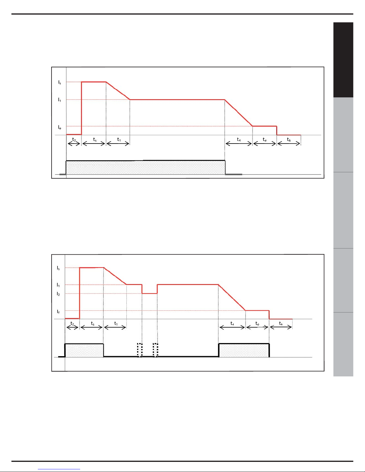
Al fine di permettere una migliore comprensione dei parametri di saldatura relativi alla
modalità MIG, quando necessario, fare riferimento agli andamenti riportati di seguito:.
t
2
: pre gas
I
s
, t
s
: corrente iniziale , tempo iniziale
t
1
: rampa I
s
->I
1
I
1
: corrente di saldatura
I
2
: corrente secondo livello
t
4
: rampa I
1
->I
e
I
e
, t
e
: corrente finale, tempo finale
t
6
: post gas
t
2
: pre gas
I
s
, t
s
: corrente iniziale , tempo iniziale
t
1
: rampa I
s
->I
1
I
1
: corrente di saldatura
I
2
: corrente secondo livello
t
4
: rampa I
1
->I
e
I
e
, t
e
: corrente finale, tempo finale
t
6
: post gas
Pulsante torciaP. T.
4. SALDATURA MIG/MAG
Pulsante torcia
MIG modalità 2t con rampe
MIG modalità 4t/4bi con rampe
Page 14
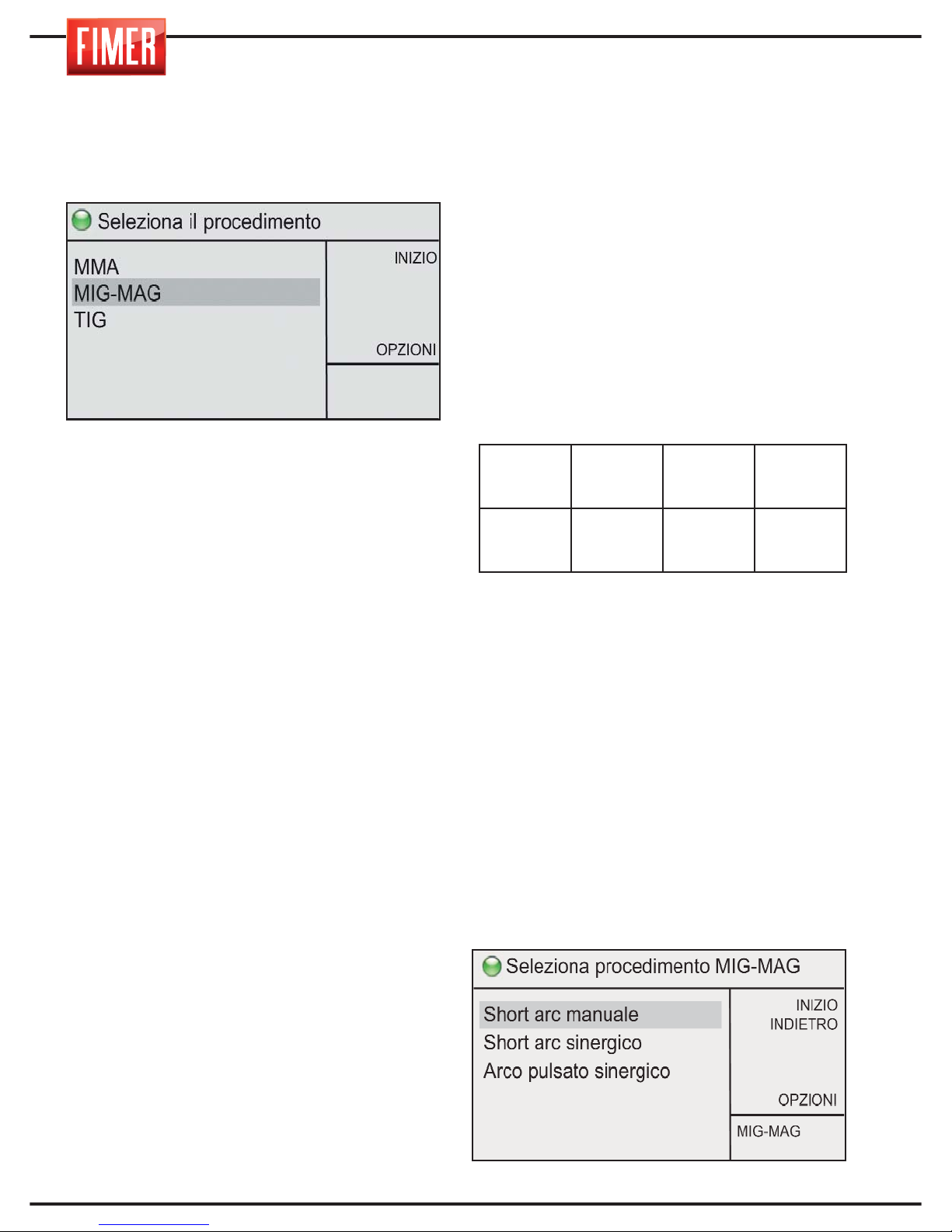
Per scegliere questa modalità di saldatura :
tramite la manopola 10 scegliere MIG e
premere per conferma.
La saldatura MIG/MAG (Metal Inert Gas e
Metal Active Gas) è una saldatura a filo
continuo che permette di utilizzare densità di
corrente più elevate rispetto alla saldatura
con elettrodi rivestiti; questo permette di
avere penetrazioni e velocità maggiori ed
ottenere un riempimento del giunto con un
numero minore di passate.
La saldatura viene eseguita sciogliendo in un
bagno di saldatura un elettrodo metallico
costituito da un filo fornito in continuazione
con velocità costante e controllata tramite la
torcia di saldatura.
Quando il filo comincia a scorrere e tocca il
pezzo da saldare, si genera l’arco elettrico;
l’arco scioglie il filo che si deposita sul pezzo
da saldare.
Questa saldatrice può utilizzare i seguenti tipi
di filo:
1. filo pieno: deve sempre essere usato con
gas protettivo.
2. filo animato per saldatura con gas: ha
nella parte centrale un prodotto minerale che
ha lo scopo di migliorare le caratteristiche di
saldatura (deve essere sempre usato con gas)
La corretta connessione della torcia e del
cavo di massa è mostrata nella tabella sotto
riportata:
Attraverso il pulsante 9 è possibile
regolare, la potenza macchina.
Vi sono tre principali modi di saldatura
MIG-MAG:
1.Short arc manuale
2.Short arc sinergico
3. Arco pulsato sinergico
4.1 SALDATURA MIG Short Arc Manuale
La rotazione della manopola 10 permette
la scelta tra i differenti modi di saldatura
MIG-MAG; la pressione della manopola
conferma la scelta effettuata.
WELDING
PROCESS
Euroconnettor
16 of Fig.1
‘+’
Front socket
14 of Fig.1
‘-’
Front socket
12 of Fig.1
MIG/MAG
TORCH
CABLE
NOT USED
EARTH
CABLE
10
Page 15
11
ESPAÑOL FRANÇAIS
DEUTSCH
ENGLISH
ITALIANO
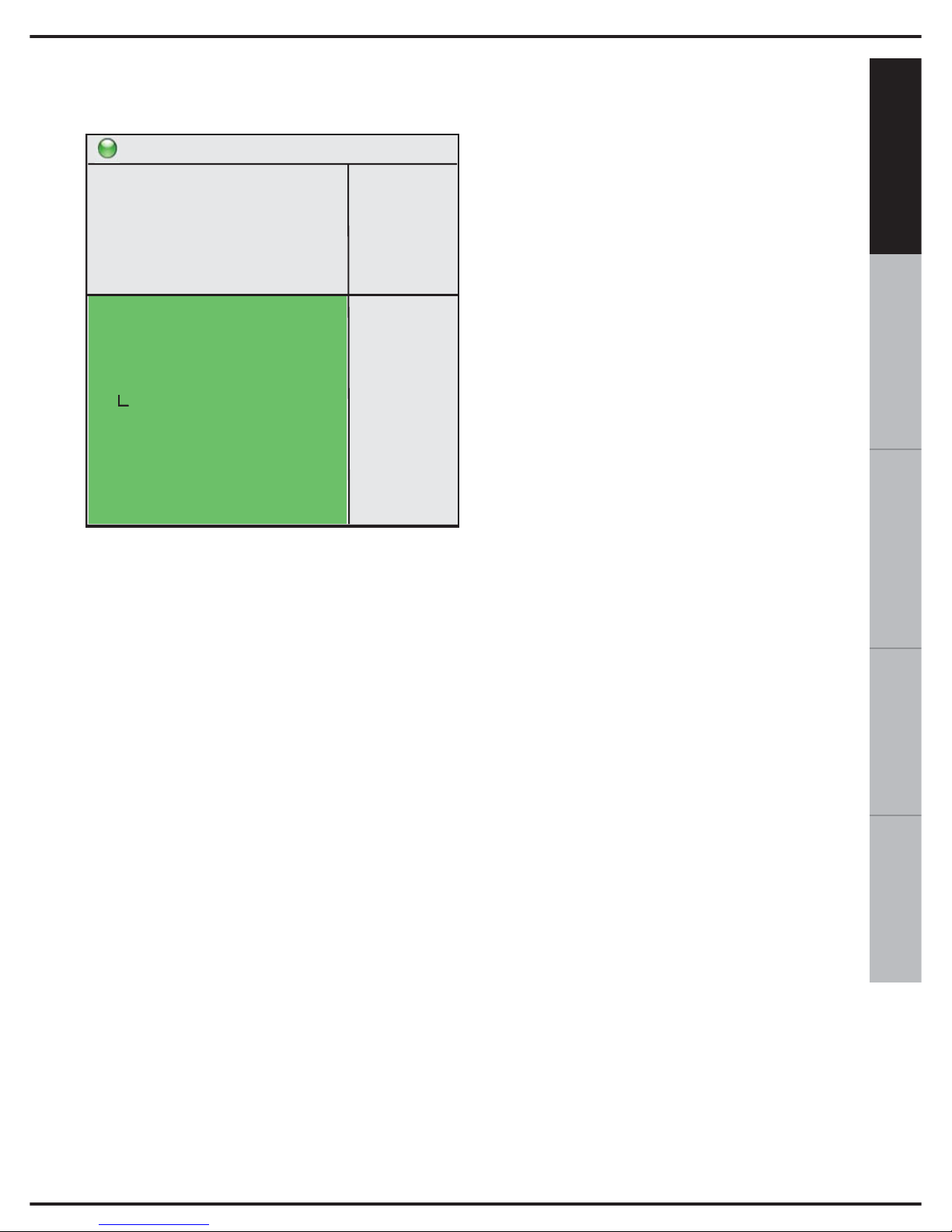
Effettuata la selezione si accede alla
schermata di saldatura:
Velocità filo: Permette di impostare la
velocità del filo utilizzato per la saldatura.
Soft-start: Permette di modificare la velocità
di accosto del filo in modo da ottenere un
innesco di saldatura morbido; valori elevati
corrispondono a velocità di accosto più
basse.
Induttanza: Permette di modificare la veloc-
ità di variazione della corrente di saldatura
per ottenere un arco più secco (valori bassi)
o più morbido (valori alti).
2t-4t-4bilevel: Permette di impostare il fun-
zionamento in modalità 2 tempi o 4 tempi
2t: Nel funzionamento in modalità 2 tempi, la
macchina effettua la saldatura per tutto il
tempo in cui il pulsante torcia è premuto.
4t: Nel funzionamento in modalità 4 tempi,
una prima pressione del pulsante torcia da
inizio alla saldatura, la seconda ne provoca
la fine
Puntatura: Permette di impostare (se diver-
so da 0) la durata massima della saldatura.
Pausa: Permette di impostare (se diverso da
0) la durata della pausa tra due successive
puntature.
Pre gas: Permette di impostare il tempo di
erogazione del gas prima dell’innesco del-
l’arco elettrico.
Post gas: Permette di impostare il tempo di
erogazione del gas dopo la fine del-
l'erogazione della corrente di saldatura.
Burnback: Permette di variare il tempo di
bruciatura del filo alla fine della saldatura.
Hot start: Permette di impostare la corrente
di innesco della saldatura in modo da
ottenere un innesco di saldatura morbido; in
genere viene usato insieme con il parametro
di Soft-start.
Pompa acqua: Permette di accendere (ON)
o spegnere (OFF) la centralina dell'acqua,
se presente.
4.2 SALDATURA MIG Short Arc Sinergico
La saldatura Mig Sinergica permette di ade-
guare facilmente i parametri di saldatura ai
differenti materiali da saldare. Durante la sal-
datura con regolazione sinergica la manopo-
la 9 di Fig 1 regola simultaneamente la ten-
sione o la velocità del filo.
Gli altri parametri vengono automaticamente
adeguati alla potenza impostata, in funzione
del tipo e del diametro del filo scelto.
La lunghezza dell’arco può essere variata in
percentuale tramite il parametro “tensione
saldatura”. La qualità della saldatura può
essere ulteriormente migliorata regolando il
parametro “Induttanza elettronica” e deposito.
Pronto a saldare
INIZIO
INDIETRO
MEM +
SPURGO
150
A
15,0
V
>
MIG-MAG
S.A.M.
velocità filo
soft start
induttanza
2t-4t-4bilevel
puntatura
pausa
pre gas
post gas
burnback
hot start
pompa acqua
1,0 m/'
0
0
2t
0,0 s
0,0 s
0,1 s
2,0 s
2,0ms
0
OFF
2,8m/'
Page 16
12
La rotazione della manopola 10 permette la
scelta tra i differenti modi di saldatura MIGMAG; la pressione della manopola conferma
la scelta effettuata.
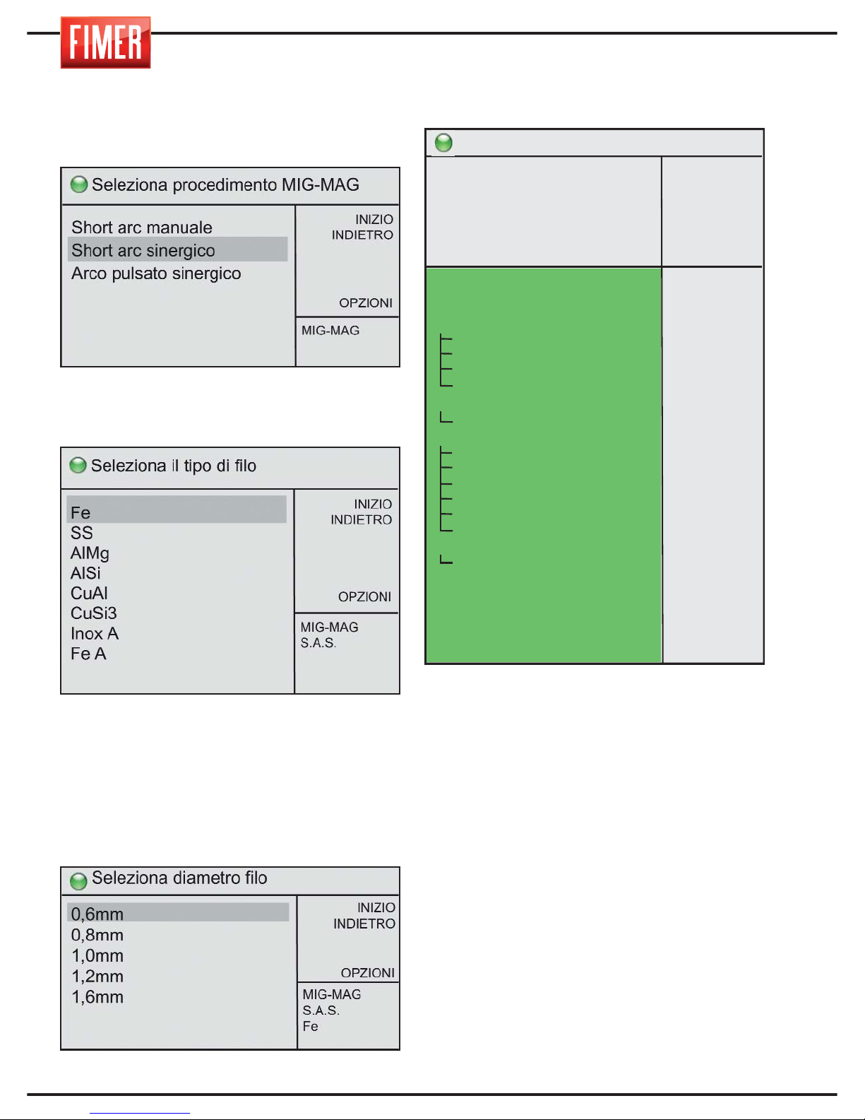
Effettuata la selezione si accede alla
schermata relativa alla scelta del materiale
del filo di saldatura:
I parametri che non appaiono sullo
schermo sono accessibili ruotando la
manopola 10.
Una volta selezionato il tipo di filo (tramite la
pressione della manopola 10), si accede alla
pagina di impostazione del diametro del filo
di saldatura.
Effettuata la selezione si accede alla
schermata di saldatura:
Lunghezza arco: Permette di variare la
tensione di riferimento usata per la saldatura
Deposito: Permette di modificare il deposito
di materiale di apporto (velocità del filo)
rispetto al valore sinergico predefinito
Induttanza: Permette di modificare la
velocità di variazione della corrente di
saldatura per ottenere un arco più rigido
(valori bassi) o più morbido (valori alti)
Doppio short: Permette di attivare (ON) o
disattivare (OFF) la modalità a due livelli,
ovvero la commutazione continua tra due
diversi livelli di corrente di saldatura
Tempo L1: Quando la modalità a due livelli
è attiva permette di impostare la durata del
primo livello di corrente
Pronto a saldare
INIZIO
INDIETRO
MEM +
SPURGO
80
A
23,2
V
>
MIG-MAG
S.A.S.
Fe
0,6mm
lunghezza arco
deposito
induttanza
doppio short
tempo L1
tempo L2
livello L2
tensione L2
2t-4t-4bilevel
secondo livello
corrente iniziale/finale
corrente iniziale
tempo iniziale
rampa ls->l1
rampa l1->le
corrente finale
tempo finale
puntatura
pausa
pre gas
post gas
burnback
soft start
hot start
pompa acqua
0,0v
0,0m/’
0
OFF
0,3s
0,3s
60%
0,0v
2t
80%
OFF
125%
0,0s
0,0s
0,0s
80%
0,0s
0,0s
0,0 s
0,1 s
2,0 s
0,0 s
0
0
OFF
10,5m/'
1,8mm
Page 17

13
ESPAÑOL
FRANÇAIS
DEUTSCH
ENGLISH
ITALIANO
Tempo L2: Quando la modalità a due livelli
è attiva permette di impostare la durata del
primo livello di corrente
Livello L2: Quando la modalità a due livelli
è attiva permette di impostare la corrente del
secondo livello (L2) rispetto alla corrente
impostata (livello L1)
Tensione L2: Quando la modalità a due
livelli è attiva permette di modificare la
tensione del secondo livello (L2) in modo
indipendente dalla tensione del livello L1
(parametro Lunghezza arco)
2t-4t-4bilevel: Permette di impostare il
funzionamento in modalità 2 tempi o 4 tempi.
2t: Nel funzionamento in modalità 2 tempi, la
macchina effettua la saldatura per tutto il
tempo in cui il pulsante torcia è premuto.
4t: Nel funzionamento in modalità 4 tempi,
una prima pressione del pulsante torcia da
inizio alla saldatura, la seconda ne provoca
la fine.
4bi: Il funzionamento è analogo alla modalità
4t con la sola differenza che pressioni brevi
(< 1s) del pulsante torcia durante la fase di
saldatura causano il passaggio tra la
corrente di primo livello I1 e quella di
secondo livello I2; una pressione prolungata
(> 1s) causa l’inizio della fase di chiusura
della saldatura.
Secondo livello: Permette di impostare il
valore di corrente relativo al secondo livello
di potenza, attivo quando il valore del
parametro 2t-4t-4bilevel è impostato su 4bi
Corrente iniziale/finale: Permette di attivare
(ON) o disattivare (OFF) la modalità con
corrente iniziale e finale.
Corrente iniziale: Permette di impostare il
livello iniziale in percentuale della corrente di
saldatura (es. 130% implica I
s
=1,30xI1)
Tempo iniziale: Nella modalità 2t permette di
impostare il tempo di applicazione della corrente
iniziale I
s
Rampa ls->l1: Permette di impostare la
durata della rampa di corrente dal livello
iniziale I
s
alla corrente di saldatura I
1.
Rampa l1->le: Permette di impostare la
durata della rampa di corrente dalla corrente
di saldatura I
1
al livello finale I
e.
Corrente finale: Permette di impostare la
corrente finale in percentuale della corrente di
saldatura (es. 80% implica I
f
=0,80xI1)
Tempo finale: Nella modalità 2t permette di
impostare il tempo di applicazione della
corrente finale I
f
Puntatura: Permette di impostare (se
diverso da 0) la durata massima della
saldatura.
Pausa: Permette di impostare (se diverso da
0) la durata della pausa tra due successive
puntature.
Pre gas: Permette di impostare il tempo di
erogazione del gas prima dell’innesco
dell’arco elettrico.
Post gas: Permette di impostare il tempo di
erogazione del gas dopo la fine
dell'erogazione della corrente di saldatura.
Burnback: Permette di variare il tempo di
bruciatura del filo alla fine della saldatura.
Soft start: Permette di modificare la velocità
di accosto del filo in modo da ottenere un
innesco di saldatura morbido; valori elevati
corrispondono a velocità di accosto più
basse.
Hot start: Permette di impostare la corrente
di innesco della saldatura in modo da
ottenere un innesco di saldatura morbido; in
genere viene usato insieme con il parametro
di Soft-start.
Pompa acqua: Permette di accendere (ON)
o spegnere (OFF) la centralina dell'acqua, se
presente.
Page 18
14
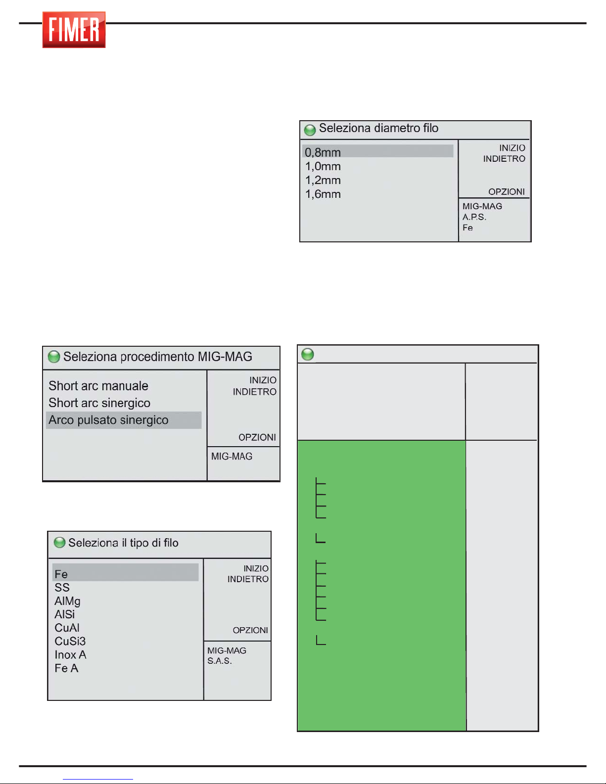
4.3 SALDATURA MIG Arco pulsato sinergico
La saldatura MIG ad arco pulsato sinergico permette di ottenere un bagno relativamente freddo
contestualmente ad una buona penetrazione.
Questa modalità di saldatura, grazie al
basso apporto di energia, è particolarmente
indicata per spessori molto sottili e per materiali quali l’acciaio inox e l’alluminio.
Durante la saldatura con regolazione sinergica la manopola 9 di Fig.1 regola la velocità
del filo (cioè la potenza di saldatura).
Gli altri parametri vengono automaticamente
adeguati alla potenza impostata, in funzione
del tipo e del diametro del filo scelto.
La rotazione della manopola 10 permette
la scelta tra i differenti modi di saldatura
MIG-MAG; la pressione della manopola
conferma la scelta effettuata.
Effettuata la selezione si accede alla
schermata relativa alla scelta del materiale
del filo di saldatura:
I parametri che non appaiono sullo schermo
sono accessibili ruotando la manopola 10.
Una volta selezionato il tipo di filo (tramite
la pressione della manopola 10), si
accede alla pagina di impostazione del
diametro del filo di saldatura.
I diametri filo potrebbero non essere
disponibili per tutti i modelli.
Effettuata la selezione si accede alla
schermata di saldatura:
Pronto a saldare
INIZIO
INDIETRO
MEM +
SPURGO
150A
30,7V
>
MIG-MAG
A.P.S.
Fe
0,8mm
lunghezza arco
deposito
doppio pulsato
tempo L1
tempo L2
livello L2
lunghezza arco L2
2t-4t-4bilevel
secondo livello
corrente iniziale/finale
corrente iniziale
tempo iniziale
rampa Is->l1
rampa I1->lf
corrente finale
tempo finale
puntatura
pausa
pre gas
post gas
burnback
soft-start
hot start
induttanza
pompa acqua
0,0v
0,0m/’
OFF
0,3s
0,3s
60%
0,0v
2t
80%
OFF
125%
0,0s
0,0s
0,0s
80%
0,0s
0,0s
0,0s
0,1 s
2,0 s
0,0
0
0
0
OFF
14,8m/'
5,0mm
Page 19

15
ESPAÑOL FRANÇAIS
DEUTSCH
ENGLISH
ITALIANO
Lunghezza arco: Permette di variare la ten-
sione di riferimento usata per la saldatura.
Deposito: Permette di modificare il deposito
di materiale di apporto (velocità del filo)
rispetto al valore sinergico predefinito.
Doppio pulsato: Permette di attivare (ON) o
disattivare (OFF) la modalità a due livelli,
ovvero la commutazione continua tra due
diversi livelli di corrente di saldatura.
Tempo L1: Quando la modalità a due livelli
è attiva permette di impostare la durata del
primo livello di corrente.
Tempo L2: Quando la modalità a due livelli
è attiva permette di impostare la durata del
primo livello di corrente
Livello L2: Quando la modalità a due livelli
è attiva permette di impostare la corrente del
secondo livello (L2) rispetto alla corrente
impostata (livello L1)
Lunghezza arco L2: Quando la modalità a
due livelli è attiva permette di modificare la
lunghezza arco del secondo livello (L2) in
modo indipendente dalla lunghezza arco del
livello L1 (parametro Lunghezza arco)
2t-4t-4bilevel: Permette di impostare il funzionamento in modalità 2 tempi o 4 tempi.
2t: Nel funzionamento in modalità 2 tempi, la
macchina effettua la saldatura per tutto il
tempo in cui il pulsante torcia è premuto.
4t: Nel funzionamento in modalità 4 tempi,
una prima pressione del pulsante torcia da
inizio alla saldatura, la seconda ne provoca
la fine.
4bi:Il funzionamento è analogo alla modalità
4t con la sola differenza che pressioni brevi
(< 1s) del pulsante torcia durante la fase di
saldatura causano il passaggio tra la corrente di primo livello I1 e quella di secondo livello I2; una pressione prolungata (> 1s) causa
l’inizio della fase di chiusura della saldatura
Secondo livello: Permette di impostare il
valore di corrente relativo al secondo livello
di potenza, attivo quando il valore del parametro 2t-4t-4bilevel è impostato su 4bi.
Corrente iniziale/finale: Permette di attivare (ON) o disattivare (OFF) la modalità
con corrente iniziale e finale.
Corrente iniziale: Permette di impostare il
livello iniziale in percentuale della corrente di
saldatura (es. 130% implica I
s
=1,30xI1)
Tempo iniziale: Nella modalità 2t permette
di impostare il tempo di applicazione della
corrente iniziale I
s
Rampa Is->I1: Permette di impostare la durata della rampa di corrente dal livello iniziale I
s
alla corrente di saldatura I
1
Rampa I1->If: Permette di impostare la durata della rampa di corrente dalla corrente di
saldatura I
1
al livello finale I
f.
Corrente finale: Permette di impostare la
corrente finale in percentuale della corrente
di saldatura (es. 80% implica I
f
=0,80xI1)
Tempo finale: Nella modalità 2t permette di
impostare il tempo di applicazione della corrente finale I
f.
Puntatura: Permette di impostare (se diverso da 0) la durata massima della saldatura.
Pausa: Permette di impostare (se diverso da
0) la durata della pausa tra due successive
puntature.
Pre gas: Permette di impostare il tempo di
erogazione del gas prima dell’innesco dell’arco elettrico.
Post gas: Permette di impostare il tempo di
erogazione del gas dopo la fine dell'erogazione della corrente di saldatura.
Burnback: Permette di variare il tempo di
bruciatura del filo alla fine della saldatura.
Soft-start: Permette di modificare la velocità
di accosto del filo in modo da ottenere un
innesco di saldatura morbido; valori elevati
corrispondono a velocità di accosto più
basse.
Hot start: Permette di impostare la corrente
di innesco della saldatura in modo da
ottenere un innesco di saldatura morbido; in
genere viene usato insieme con il parametro
di Soft-start.
Induttanza: Permette di modificare la velocità di variazione della corrente di saldatura
per ottenere un arco più rigido (valori bassi)
o più morbido (valori alti).
Pompa acqua: Permette di accendere (ON)
o spegnere (OFF) la centralina dell'acqua,
se presente.
Page 20
16
Fare riferimento alla tabella seguente per l’impostazione della corretta corrente di saldatura:
5. COLLEGAMENTO PER
SALDATURA MIG
Il collegamento dei cavi di saldatura avviene
con un sistema di attacco rapido che impiega
appositi connettori.
5.1. TORCIA MIG
Si raccomanda di effettuare dei controlli
periodici sullo stato della torcia di saldatura;
in particolare, occorre verificare l’ugello/diffusore del gas (Fig. 4A) la punta guidafilo
(Fig. 4B), e la guaina interna alla torcia.
Queste parti devono essere ben pulite e
intatte. Sostituire il guidafilo quando il filo
non scorre regolarmente.
N.B. Per ogni filo e diametro corrispondono
un’ apposita punta guidafilo e guaina.
Accertarsi che siano corrette.
5.2 COLLEGAMENTO PER SALDATURA
MIG con torcia tradizionale
1) Collegare il cavo di massa all’apposito
connettore “-“ posto sul frontale (12 di Fig 1).
L’inserimento deve avvenire allineando la
chiavetta con la scanalatura e stringendo il
connettore fino all’arresto tramite una rotazione
in senso orario. Non stringere troppo!
2) Collegare la torcia all’apposito
connettore posto sul frontale (16 di Fig 1),
avvitandolo in senso orario fino all’arresto.
Non stringere troppo!
Attenzione: la macchina viene fornita di serie
con la propria torcia per saldatura MIG (Fig 4)
Questo accessorio avrà una lunga durata se si
effettuano dei controlli periodici dell’ugello del gas
(Fig 4A) e alla punta guidafilo (Fig 4B). Queste
parti devono essere ben pulite e intatte. Sostituire
il guidafilo quando il filo non scorre regolarmente.
5.3 COLLEGAMENTO PER SALDATURA
MIG con torcia Push-Pull
1) Collegare il cavo di massa all’apposito
connettore “-“ (12 di figura 1). L’inserimento deve
avvenire allineando la chiavetta con la scanalatura
e stringendo fino all’arresto tramite una
rotazione in senso orario. Non stringere troppo!
2) Collegare la torcia all’apposito connettore
posto sul frontale (16 di Fig 1), avvitandolo in
senso orario fino all’arresto. Non stringere troppo!
3) Collegare il connettore dei segnali della
torcia all’apposita presa femmina.
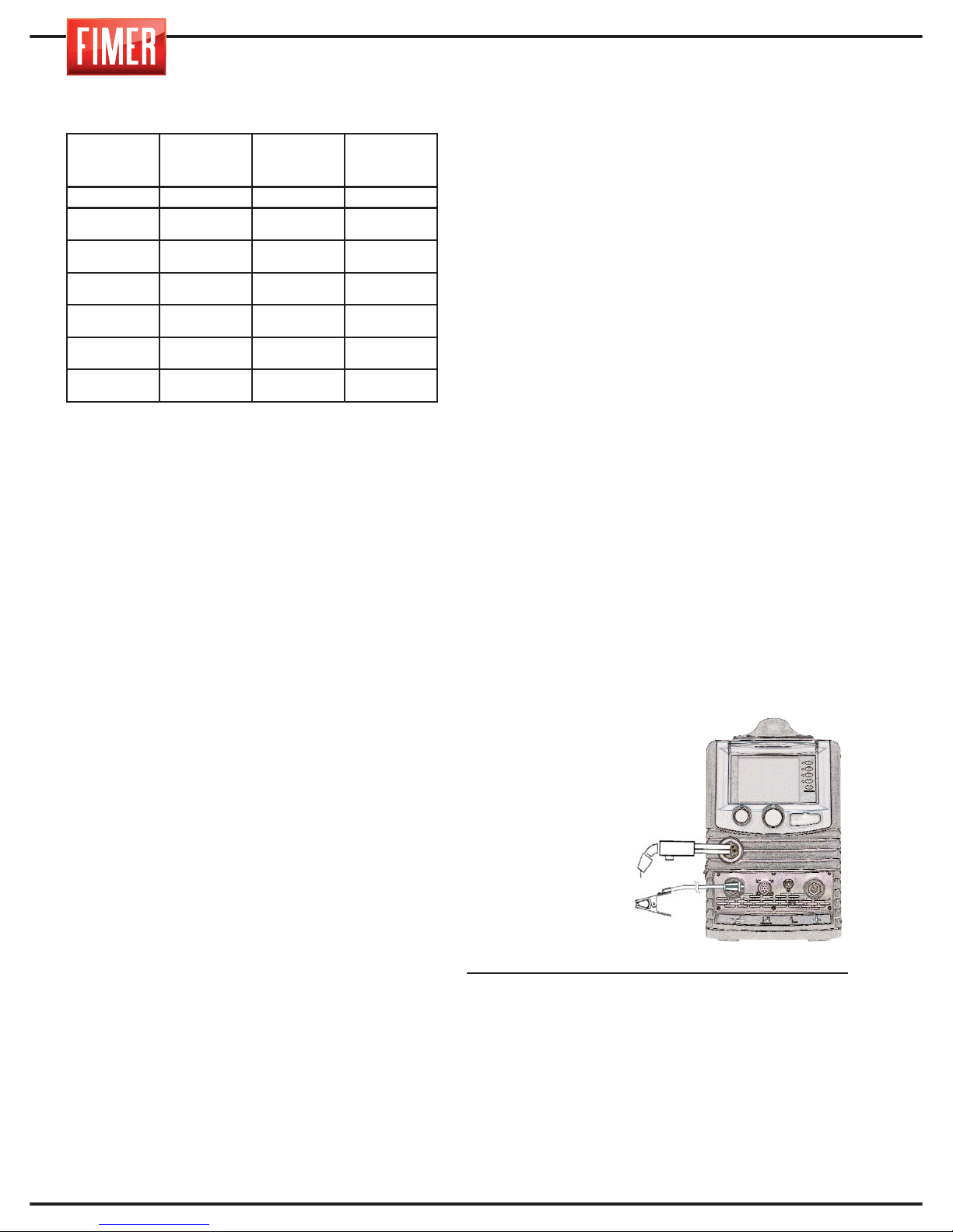
SALDATURA MIG:
Prima di effettuare il collegamento della bombola
occorre verificare che la bombola contenga gas
inerte. Non utilizzare altri gas.
Connettere alla bombola il riduttore di pressione, dopo di che collegare a quest’ultimo il
tubo del gas della torcia.
Le saldature MIG vengono generalmente eseguite in c.c. con polo positivo (“+”
vedi fig.5).
Il cavo della torcia
MIG andrà collegato all’euroconnettore (16 di fig.1), men-
tre il cavo di massa del pezzo da saldare andrà collegato alla presa frontale “-” (12 di fig.1).
A questo punto si potrà regolare la corrente di saldatura tramite il potenziometro (9 di
fig.1) posto sul pannello frontale.
Il diametro dell’elettrodo e il valore della corrente di saldatura dovranno essere scelti in
funzione dello spessore del pezzo da saldare.
SPESSORE
DEL
PEZZO
DIAMETRO
FILO
CORRENTE
DI
SALDATURA
ARCO
mm mm A
0.8 - 1.0 0.6 - 0.8 60-100
Short-Arc
1.5 - 2.0 0.8 - 1.0 80-120
Short-Arc
2.0 - 3.0 1.0 - 1.2 100-130
Short-Arc
3.0 - 4.0 1.2 120-200
Short-Arc
> 4.0 1 150÷200
Spray-Arc
> 4.0 1.2 200÷300
Spray-Arc
Fig.5
Page 21
17
ESPAÑOL FRANÇAIS
DEUTSCH
ENGLISH
ITALIANO
6. INNESCO DELL’ARCO MIG
Il procedimento di saldatura MIG-MAG si realizza quando si crea un arco elettrico fra un
filo fusibile ed il pezzo da saldare sotto la protezione di una atmosfera gassosa. Questa
può essere un’atmosfera inerte (Argon) o attiva (CO² o una miscela di Argon e CO²).
Il filo viene fatto avanzare con continuità da
un trainafilo attraverso la torcia fino al bagno
di fusione. Si possono usare o un filo pieno
o un filo animato.
Le modalità di trasferimento del materiale
d’apporto definiscono diverse tipologie di arco:
- la tensione influenza direttamente l’aspetto
del cordone, ma le dimensioni della superficie saldata possono essere variate a seconda delle esigenze, agendo manualmente sul
movimento della torcia in modo da ottenere
depositi variabili con tensione costante.
- la velocità di avanzamento del filo è in
relazione con la corrente di saldatura.
7. REGOLAZIONE
DELLA SALDATRICE
Una volta impostata la tensione di saldatura
mantenere la lunghezza dell’arco elettrico tra i
5 e i 10 mm e regolare la velocità del filo per
ottenere il miglior risultato di saldatura. Inizialmente fare una prova di saldatura su un campione ben pulito da patine, ruggine o vernice.
NOTA Quando si preme il pulsante della torcia si determinano queste tre funzioni:
- flusso del gas
- avanzamento del filo
- corrente di saldatura.
8. COME OTTENERE I MIGLIORI
RISULTATI DI SALDATURA
1. Inclinare la torcia di circa 45° rispetto al pez-
zo da saldare. Mantenere l’ugello del gas (Fig.
4A) a circa 6 mm dal pezzo da saldare.
2. Muovere la torcia con continuità spingendola e non tirandola. Questo garantisce la protezione gassosa dell’arco.
3. Evitare di saldare in presenza di forte vento. Un vento troppo forte può portare via il
gas dal bagno di saldatura e quindi determinarne una saldatura porosa (debole).
4. Mantenere il filo pulito: non usare mai fili arrugginiti.
5. Evitare pieghe e spirali sul cavo della torcia che rischiano di compromettere lo scorrimento del filo.
6. Quando si cambia il rocchetto del filo, pulire
il tubetto guidafilo con aria compressa.
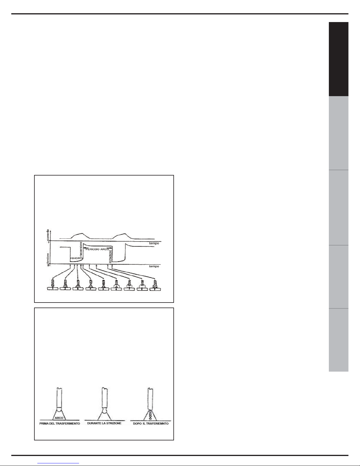
SHORT ARC (trasferimento a corto circuito):
fa entrare l’elettrodo a contatto diretto
con il bagno , si fa quindi un cortocircuito con effetto fusibile da parte del filo che
si interrompe, dopo di che l’arco si riaccende ed il ciclo si ripete.
SPRAY ARC (trasferimento a spruzzo):
consente alle gocce di staccarsi dall’elettrodo e in un secondo tempo giungono nel
bagno di fusione.
La visibilità dell’arco riduce la necessità di
una rigida osservanza delle tabelle di regolazione da parte dell’operatore che ha la
possibilità di controllare direttamente il bagno
di fusione.
Page 22
18
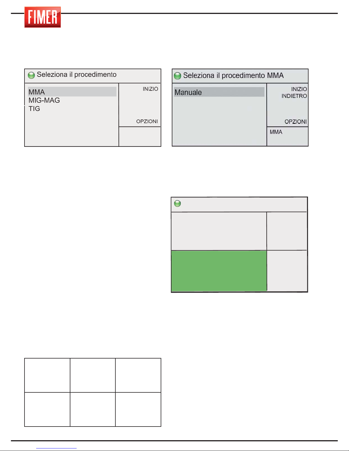
9. SALDATURA MMA
Per scegliere questa modalità di saldatura:
Tramite la manopola 10 scegliere MMA e
premere per conferma.
La saldatura ad arco elettrico con elettrodo
rivestito MMA (Metal Manual Arc) o SMAW
(Shilded Metal Arc Welding) è un
procedimento di saldatura manuale che
sfrutta il calore gen erato da un arco elettrico
che scocca tra un elettrodo fusibile rivestito
ed i pezzi da saldare. Questo procedimento
consente di realizzare giunti in qualunque
posizione, in officina, all' aperto, in zone
ristrette o di difficile accesso.
Con le TM 236 è possibile saldare qualsiasi
tipo di elettrodo e diametro. L’innesco
dell’arco avviene avvicinando l’elettrodo al
pezzo da saldare.
La corretta connessione della pinza porta
elettrodo e del cavo di massa è mostrata
nella tabella sotto riportata:
Verificare sempre che la massa e la pinza
porta elettrodo siano ben separate.
9.1 SALDATURA MMA Manuale
Si accede a queste modalità di
funzionamento premendo la manopola 10.
Effettuata la selezione si accede alla
schermata di saldatura:
La manopola 9 di figura 1 permette di
regolare la corrente di saldatura (pezzi da
saldare di spessore più elevato, richiedono
correnti maggiori).
Tramite la manopola 10 è possibile inoltre
regolare gli altri parametri mostrati in figura:
Arc Force: Permette di impostare la
percentuale di incremento di corrente,
rispetto
alla corrente di saldatura, che la saldatrice
può forzare allo scopo di mantenere ben
innescato l’arco.
Hot Start: Permette di impostare la
percentuale di incremento di corrente,
rispetto alla corrente di saldatura, che la
saldatrice può forzare al momento
dell’innesco dell’arco.
Durata hot start: Permette di impostare il
tempo durante il quale viene forzata la
corrente di hot start.
Controllo remoto: Permette di accendere
(ON) o spegnere (OFF) il controllo remoto
dell’intensità di corrente erogata
PROCESSO DI
SALDATURA
Presa Frontale
+
14 di Fig.1
Presa Frontale
-
12 di Fig.1
MMA
PINZA PORTA
ELETTRODO
CAVO MASSA
Pronto a saldare
INIZIO
INDIETRO
MEM +
OPZIONI
arc force
hot start
durata hot start
controllo remoto
20%
20%
0.5s
OFF
MMA
Manuale
150
A
15,0V
>
Page 23
19
ESPAÑOL FRANÇAIS
DEUTSCH
ENGLISH
ITALIANO
10. TABELLA DI SALDATURA
Attraverso la tabella riportata di seguito sarà
possibile calcolare la corrente di saldatura a
seconda dell’elettrodo utilizzato.
11. COLLEGAMENTO PER
SALDATURA MMA
L’inserimento dei connettori “dinse” deve
avvenire allineando la “chiavetta” con la
scanalatura e stringendo fino all’arresto
tramite una rotazione in senso orario.
Pinza porta elettrodo e massa sono da
collegare alla polarità “+” e “-” a seconda
della specifica riportata sulla confezione degli
elettrodi utilizzati.
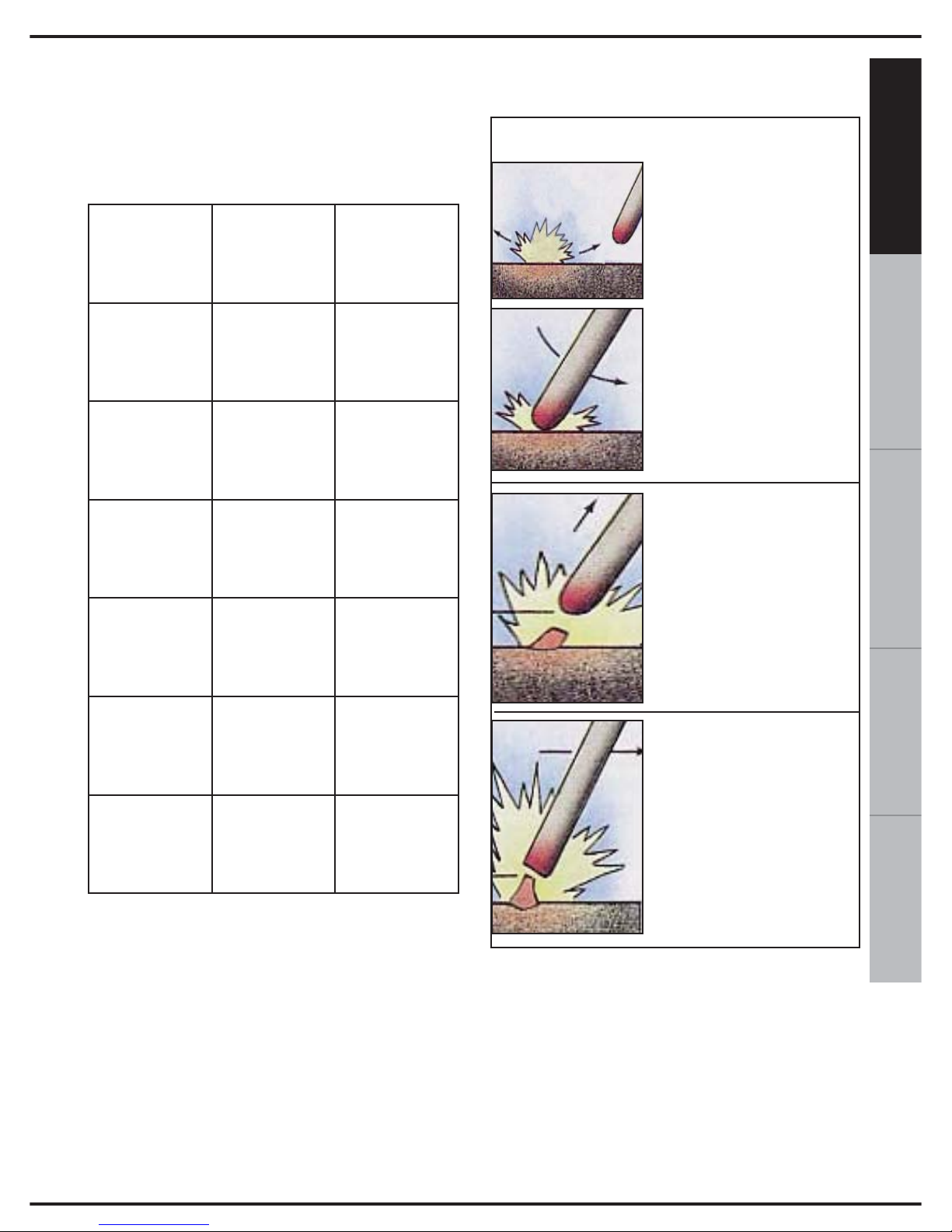
12. INNESCO DELL’ARCO
SPEGNIMENTO
Va effettuato soffermandosi un attimo sul
cratere finale (cioè sulla fine del cordone),
ritornanti lentamente sul cordone già
depositato per circa due centimetri e, solo a
questo punto, allontananti l'elettrodo per
spegnere l'arco.
DIAMETRO
ELETTRODO
CORRENTE DI
SALDATURA
LUNGHEZZA
ELETTRODO
mm A mm
2.0 45 ÷ 60
300
2.5 60 ÷ 100
300
3.25 90 ÷ 140
450
4.0 140 ÷ 170
450
5.0 190 ÷ 230
450
Creare il contatto per
accendere l’arco a circa
5 cm di distanza rispetto
al punto di inzio
saldatura.
Ravvicinare immediatamente
l'elettrodo al pezzo senza
toccarlo in modo che l'arco
rimanga acceso.
Portarsi con una certa
velocità, senza spegnere
l'arco, al punto dove si
intende iniziare il cordone
di saldatura.
Iniziare la saldatura
avanzando lentamente.
La distanza fra la punta
dell'elettrodo ed il pezzo
deve essere circa uguale
al diametro dell'elettrodo
che si sta utilizzando.
ACCENSIONE
Page 24
20
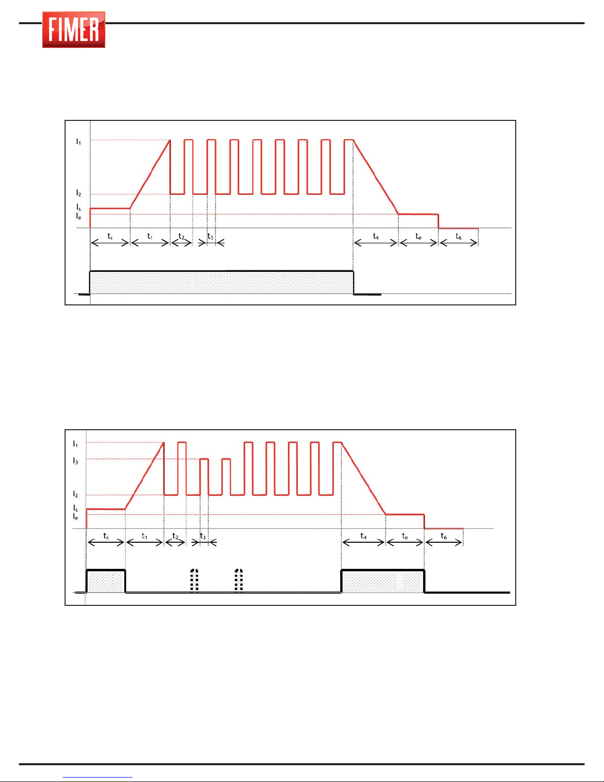
Al fine di una migliore comprensione delle descrizioni dei parametri di saldatura riportati, relativi alla modalità TIG, quando necessario fare riferimento agli andamenti
riportati di seguito:
Is, ts: corrente iniziale, tempo iniziale
I
1
: corrente di saldatura
I
2
: corrente di base
I
e
, te: corrente finale, tempo finale
t
3/t2
x100: bilanciamento
1/t
2
: frequenza
t
6
: post gas
Is, ts: corrente iniziale, tempo iniziale
I
1
: corrente di saldatura
I
3
: corrente 2° livello
I
2
: corrente di base
I
e
, te: corrente finale, tempo finale
t
3/t2
x100: bilanciamento
1/t
2
: frequenza
t
6
: post gas
Pulsante torcia
Pulsante torciaP. T.
13. SALDATURA TIG
MIG modalità 2t con rampe
MIG modalità 4t/4bi con rampe
Page 25
21
ESPAÑOL FRANÇAIS
DEUTSCH
ENGLISH
ITALIANO
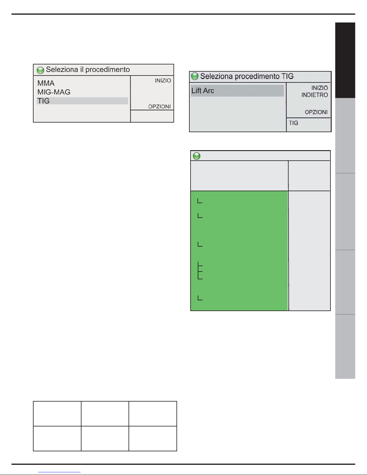
Per scegliere questa modalità di saldatura :
tramite la manopola 10 scegliere TIG e
premere per conferma.
La saldatura in gas inerte con elettrodo
infusibile di tungsteno (TIG: Tungsten Inert
Gas) è un procedimento di saldatura in cui il
calore è prodotto da un arco che scocca tra un
elettrodo in tungsteno (che non si consuma)
ed i pezzi da saldare. La saldatura viene
eseguita portando a fusione i lembi del pezzo
da saldare oppure aggiungendo
eventualmente altro materiale d’apporto
proveniente da specifiche bacchette così da
realizzare il giunto.
L’accensione dell’arco avviene toccando con
l'elettrodo il pezzo da saldare e sollevandolo
dopo averlo toccato (innesco lift).
Il procedimento TIG si adatta a qualsiasi
posizione di lavoro e può essere applicato anche
su lamiere di spessore assai ridotto (0,2-0,3 mm).
Il procedimento TIG si contraddistingue per
avere una grande facilità di controllo dell'arco,
una sorgente termica potente e concentrata e
per poter facilmente controllare la quantità di
materiale d'apporto.
Questo rende il procedimento TIG
particolarmente indicato per saldature di
precisione su una vasta gamma di spessori,
per saldature in posizioni difficoltose e su
tubazioni, dove è richiesta la piena
penetrazione. Il procedimento TIG consente
la saldatura di svariate tipologie di materiali,
come materiali ferrosi, leghe di nichel, rame,
titanio, magnesio…;
Durante la saldatura il potenziometro 9 di fig 1
regola la corrente di saldatura.
La corretta connessione della torcia e del
cavo di massa è mostrata nella tabella
sotto riportata:
13.1 SALDATURA TIG (Lift-Arc)
La rotazione della manopola 10 permette la
scelta tra i differenti modi di saldatura TIG; la
pressione della manopola conferma la
scelta effettuata.
Effettuata la selezione si accede alla
schermata di saldatura:
REGOLAZIONI E PARAMETRI:
Attraverso il pulsante 9 è possibile regolare,
in corrente, la potenza macchina.
Tramite la manopola 10 è possibile regolare i
parametri di saldatura visualizzati sul display:
2t-4t-4bilevel: Permette di impostare il funzionamento in modalità 2 tempi o 4 tempi
2t: Nel funzionamento in modalità 2 tempi,
la pressione del pulsante causa la fuoriuscita del gas di protezione; al sollevamento
dell’elettrodo dal pezzo si innesca l’arco
elettrico, con esecuzione della Corrente
iniziale e/o della Rampa di salita,che rimane
acceso per tutto il tempo in cui il pulsante
rimane premuto. Al rilascio la macchina
inizia la Rampa di discesa della corrente e/o
la Corrente finale, se impostate.
PROCESSO DI
SALDATURA
Presa Frontale
+
14 di Fig.1
Presa Frontale
-
12 di Fig.1
TIG CAVO MASSA CAVO TORCIA
Pronto a saldare
INIZIO
INDIETRO
MEM +
OPZIONI
150A
15,0V
>
TIG
Lift
2t-4t 4bilevel
corrente 2° livello
corrente iniziale
tempo iniziale
rampa di salita
rampa di discesa
corrente finale
tempo finale
post gas
pulsazione
corrente di base
frequenza
bilanciamento
pompa acqua
controllo remoto
corrente minima
puntatura
2t
-50%
50%
0,0s
0,0s
0,0s
20%
0,0s
5,0s
OFF
50%
10,0
50%
OFF
OFF
10A
0,0s
Page 26

22
4t: Nel funzionamento in modalità 4 tempi, la
prima pressione del pulsante causa la fuoriuscita del gas di protezione, quindi al sollevamento dell’elettrodo dal pezzo si innesca
l’arco elettrico.
La corrente erogata è quella corrispondente
al parametro Corrente iniziale fintanto che il
pulsante non viene rilasciato, quindi la
macchina esegue la Rampa di salita se
impostata. Alla successiva pressione del pulsante la macchina esegue la Rampa di
discesa della corrente, se impostata, e la
Corrente finale (fino al rilascio del pulsante),
quindi la fase di Post gas. Qualora il pulsante venga rilasciato subito, la macchina
esegue la Rampa di discesa della corrente
(se impostata), quindi la fase di Post gas.
4bi: Il funzionamento è analogo alla modalità 4t con la sola differenza che pressioni
brevi (< 1s) del pulsante torcia durante la
fase di saldatura (ovvero dopo l’esecuzione
della Rampa iniziale) causano il passaggio
tra la corrente di primo livello I
1
e quella di
secondo livello I
2
; una pressione prolungata
(> 1s) causa l’inizio della fase di chiusura
della saldatura (Rampa di discesa e/o
Corrente finale se impostate)
Corrente 2° livello: Qualora venga
selezionata il valore 4bi del parametro 2t-4t4bilevel permette di impostare la corrente di
2° livello in percentuale della corrente di saldatura.
Corrente iniziale: Permette di impostare il
valore a cui si porta la corrente di saldatura
subito dopo l'innesco dell'arco elettrico.
Tempo iniziale: Permette di impostare il
tempo per cui è applicata la corrente stabilita dal parametro Corrente iniziale.
In modalità 4t/4bi (se il parametro
Puntatura è uguale a 0) tale tempo è ininfluente e la corrente iniziale viene mantenuta fintanto che il pulsante torcia viene
mantenuto premuto.
Rampa di salita: Permette di impostare la
durata della rampa di salita della corrente di
saldatura.
Rampa di discesa: Permette di impostare la
durata della rampa di discesa della corrente
di saldatura.
Corrente finale: Permette di impostare il
valore a cui si porta la corrente di saldatura
al completamento della rampa di discesa.
Tempo finale: Permette di impostare il
tempo per cui è applicata la corrente stabilita dal parametro Corrente finale.
In modalità 4t/4bi tale tempo è ininfluente e
la corrente finale viene mantenuta fintanto
che il pulsante torcia viene mantenuto premuto.
Post gas: Permette di impostare il tempo di
erogazione del gas dopo la fine dell'erogazione della corrente di saldatura.
Pulsazione: Permette di attivare (Hz) o disattivare (OFF) la modalità di saldatura pulsata; con la modalità di saldatura pulsata attiva
(Hz) la macchina eroga per un certo periodo
di tempo la corrente di saldatura e per un
altro periodo di tempo la corrente definita dal
parametro Corrente di base. Il numero di
impulsi di corrente per unità di tempo è dato
dal valore del parametro Frequenza.
La pulsazione è attuata solo durante la fase
di saldatura e non nelle fasi di corrente
iniziale/finale o durante le rampe.
Corrente di base: Permette di impostare la
corrente di base attuata durante la generazione della pulsazione.
Frequenza: Permette di impostare il numero
di impulsi di corrente per unità di tempo
quando la modalità di saldatura pulsata è
attiva.
Bilanciamento: Rappresenta la percentuale
di tempo per cui è applicata la corrente di
saldatura quando la modalità di saldatura
pulsata è attiva.
Pompa acqua: Permette di accendere (ON)
o spegnere (OFF) la centralina dell'acqua,
se presente.
Controllo remoto: Permette di accendere
(ON) o spegnere (OFF) il controllo remoto
dell’intensità di corrente erogata.
Corrente minima:Permette di impostare la
corrente minima di uscita quando il controllo
remoto è al minimo di regolazione.
Puntatura: Permette di impostare (se diverso da 0) la durata massima della saldatura.
Page 27
23
ESPAÑOL FRANÇAIS
DEUTSCH
ENGLISH
ITALIANO
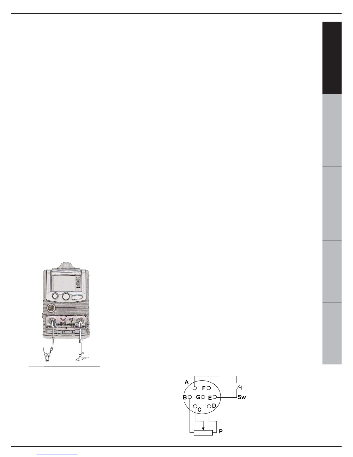
14. COLLEGAMENTO PER
SALDATURA TIG
1) Collegare il cavo di massa all’apposito
connettore + posto sul frontale (14 di fig 1).
L’inserimento deve avvenire allineando la
chiavetta con la scanalatura e stringendo
fino all’arresto tramite una rotazione in senso
orario. Non stringere troppo!
2) Collegare la torcia all’apposito connettore “-”
posto sul frontale (12 di fig 1).
3) L’inserimento deve avvenire allineando la
chiavetta con la scanalatura e stringendo fino
all’arresto tramite una rotazione in senso
orario. Non stringere troppo!
4) Collegare il connettore dei segnali del
pulsante torcia all’apposita presa.
SALDATURA TIG:
Prima di effettuare il collegamento della bombola
occorre verificare che la bombola contenga gas
inerte. Non utilizzare altri gas.
Connettere alla bombola il riduttore di pressione, dopo di che
collegare a quest’ultimo il tubo del gas
della torcia.
Le saldature TIG vengono generalmente
eseguite in c.c. con
polo negativo (“-” vedi
fig.6).
Il cavo della torcia TIG andrà quindi inserito
nella presa negativa (12 di fig.1), mentre il
cavo di massa del pezzo da saldare andrà
collegato alla presa positiva (14 di fig.1).
A questo punto si potrà regolare la corrente di saldatura tramite il potenziometro
(9 di fig.1) posto sul pannello frontale.
Il diametro dell’elettrodo e il valore della corrente di saldatura dovranno essere scelti in
funzione delle caratteristiche del materiale da
saldare.
15.COLLEGAMENTO
DELL’ALIMENTAZIONE
Prima di collegare la macchina controllare
tensione, numero di fasi e frequenza di
alimentazione. La tensione di alimentazione
ammissibile è indicata sulla targa dati della
macchina. Verificate il corretto collegamento
a terra della saldatrice. Verificare inoltre che
la spina fornita in dotazione con l’apparato sia
di tipo compatibile con la presa di
distribuzione locale.
Assicuratevi che l’alimentazione fornisca
una potenza sufficiente per il
funzionamento della macchina (range di
tensioni). La macchina è fornita di uno
specifico cavo di alimentazione che non
dovrebbe essere prolungato; nel caso ciò
fosse necessario, usarne uno di sezione
uguale o maggiore a quello della macchina
in funzione della lunghezza del cavo.
È necessario utilizzare un cavo tripolare + terra
con sezione uguale o maggiore a 2.5 mm².
16. COLLEGAMENTO REMOTO
In figura 7 sono riportati i collegamenti del
connettore remoto (13 di fig 1).
Dove:
Sw è il pulsante torcia
P è il potenziometro
per il controllo della
corrente
Fig.6
Fig.7
Page 28
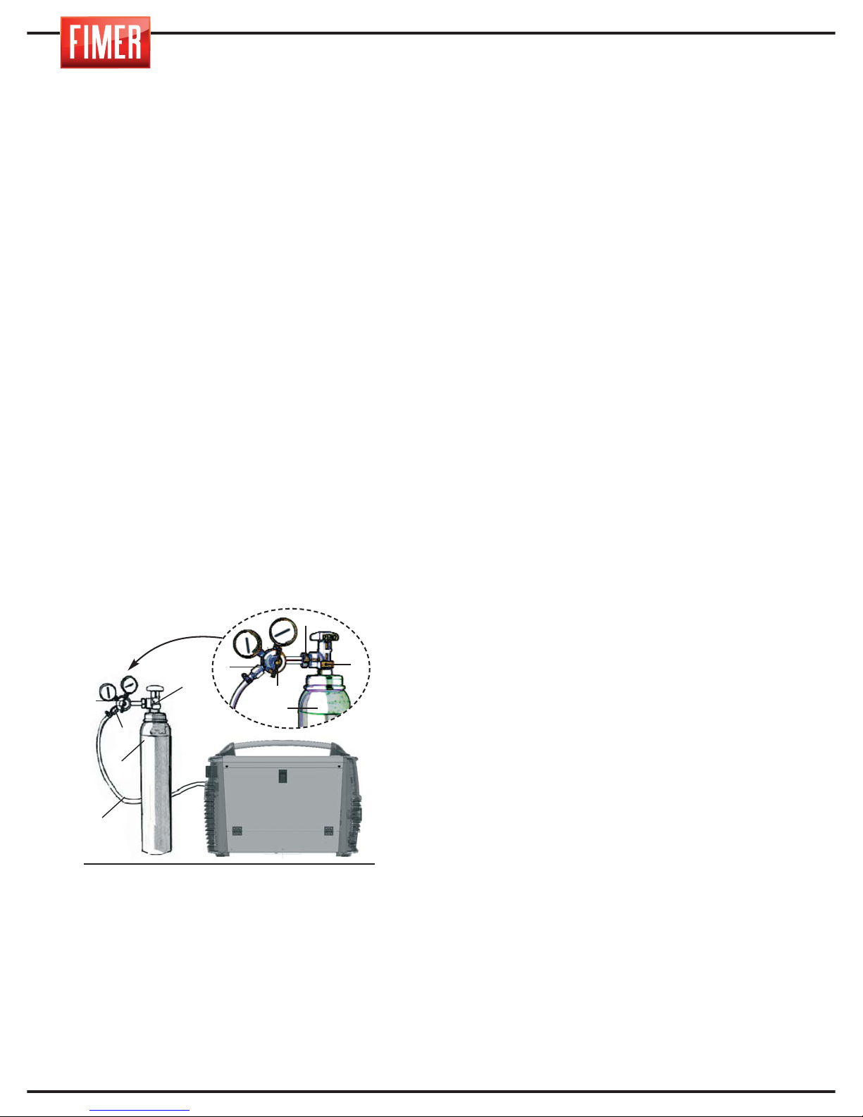
24
16.1 CONTROLLO REMOTO CORRENTE
DI SALDATURA
Tramite il connettore remoto 13 di Fig 1 è
possibile portare la regolazione di corrente
vicino al punto in cui si sta eseguendo la
saldatura.
Per far questo è necessario realizzare il
collegamento al potenziometro P mostrato in
figura 7. Il valore del potenziometro non è
critico: sono utilizzabili componenti tra
2.2kOhm e 10kOhm 1/2W.
Ruotando il potenziometro è possibile settare
la corrente di saldatura in un range
compreso tra la corrente minima impostata
da display e il valore impostato.
17. COLLEGAMENTI DELLE USCITE
Il collegamento dei cavi di saldatura
avviene con un sistema di attacco rapido
tipo dinse che impiega appositi connettori.
18. COLLEGAMENTO DELLA
BOMBOLA E DEL
REGOLATORE DEL GAS
Solo per saldatura TIG e MIG nel caso si
intenda procedere alla saldatura MMA
saltare completamente questo paragrafo.
1. Collegare il regolatore di pressione (2) alla
bombola (3). Accertarsi che il regolatore sia
adeguato alla pressione della bombola.
Stringere il dado (6) di collegamento del
regolatore (2) alla bombola (3). (Prestare la
massima attenzione a non stringere troppo;
un’eccessiva forza di serraggio può danneggiare la valvola (1) della bombola (3).)
2. Connettere il tubo del gas (4) al regolatore (2) assicurandolo con una fascetta
stringitubo (5).
3. Verificare il corretto collegamento del tubo
del gas alla saldatrice.
4. Aprire la valvola (1) della bombola (3).
Premere il pulsante della torcia e verificare
che il flusso del gas avvenga correttamente.
Per eseguire questa operazione aprire le frizioni del motore.
Attenzione: Le bombole contengono gas a
pressione elevata; maneggiarle con cura.
Un trattamento improprio può determinare
gravi incidenti.
Non sovrapporre le bombole e non esporle a calore eccessivo, a fiamme o a scintille. Non picchiare tra di loro le bombole.
Contattare il proprio fornitore per maggiori informazioni riguardo all’uso e alla
manutenzione delle bombole.
Attenzione: Non usare la bombola se danneggiate: in questo caso, informare immediatamente il fornitore.
19. MANUTENZIONE ORDINARIA
DELLA MACCHINA
Ogni tre mesi rimuovere periodicamente la
polvere dalle bocchette di aspirazione dell’aria
usando aria compressa a bassa pressione.
Dirigere sempre il getto d’aria dall’interno
della macchina verso l’esterno in modo da
evitare di spingere sporcizia all’interno della saldatrice.
Per effettuare questa operazione accertarsi che la macchina non sia collegata alla
rete elettrica.
4
3
2
1
6
2
5
1
3
5
Fig.8
Page 29
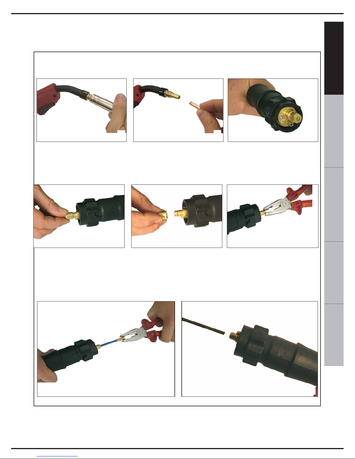
25
ESPAÑOL FRANÇAIS
DEUTSCH
ENGLISH
ITALIANO
In caso di sostituzione della guaina guidafilo seguire con attenzione queste istruzioni:
• Lato torcia: rimuovere l’ugello gas (A)
• Svitare la punta guidafilo (B)
• Lato connettore (C): svitare il dado di terminazione (D,E) e afferrare la fine della guaina
con una pinza e iniziare ad estrarla (F)
• Completare l’estrazione della guaina (G)
A
B
C
D
E
F
• Inserire la nuova guaina e spingerla dentro fino in fondo (H)
• Riavvitare la punta guidafilo (B) sulla torcia
• Completare la sostituzione della guaina riavvitando l’ugello gas (A)
G
H
20. SOSTITUZIONE DELLA GUAINA GUIDAFILO DELLA TORCIA
Nell’eseguire questa operazione assicurarsi di non smarrire l’O-RING (guarnizione in
gomma) che garantisce la tenuta senza perdite del gas.
Page 30
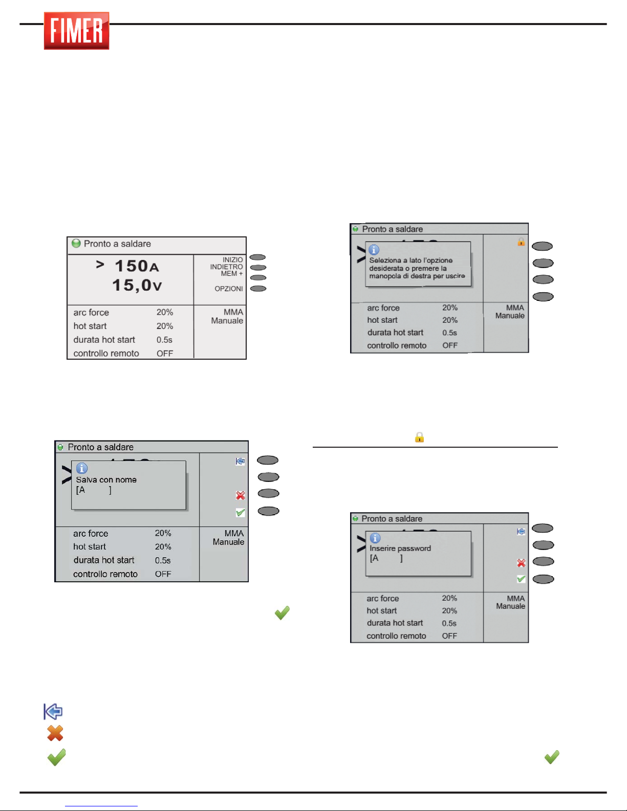
26
21. MEMORIZZAZIONE DEL PUNTO DI
LAVORO
Come illustrato nei paragrafi precedenti la
saldatrice permette un notevole
personalizzazione del punto di lavoro (sia durante
il funzionamento in manuale che in sinergico).
Il punto di lavoro ottimizzato per un pezzo da
saldare può essere salvato in memoria e
richiamato rapidamente in seguito.
Per salvare un nuovo punto di lavoro seguire
le seguenti istruzioni:
1. Stabilire i parametri opportuni per la
saldatura che si vuole impostare.
2. Premere il pulsante MEM+ (4 di fig 1).
3. Ruotando la manopola 10 (fig 1) scegliere
la prima lettera del nome con cui si vuole
salvare il punto di lavoro
4. Premere la manopola 10 per confermare
la scelta della lettera.
5. Ripetere i passi 2 e 3 fino al
completamento del nome.
6. Confermare il nome premendo il pulsante
Da questo momento il punto di lavoro viene
memorizzato col proprio nome e viene mostrato
assieme agli altri procedimenti di saldatura.
Significato dei pulsanti:
back sp: cancella l’ultima lettera inserita.
Cancella: annulla l’operazione eseguita.
OK: conferma il nome del punto di lavoro.
22. BLOCCO DEL PUNTO DI LAVORO
La saldatrice permette di bloccare le funzioni
delle manopole 9 e 10 in modo che, fissato
un punto di lavoro, esso non sia più
modificabile se non da personale in
possesso della password di sblocco che può
essere definita a discrezione dell’utente.
Per procedere con il blocco del punto di lavoro
occorre innanzitutto fissare il punto di lavoro,
ovvero impostare tutti i parametri necessari al
fine di ottenere il risultato di saldatura voluto.
Una volta fatto ciò, procedere come
indicato di seguito:
1. Premere per circa 5 secondi la manopola
9 di fig.1; apparirà il messaggio riportato in Fig.A.
Selezionare quindi il tasto 1 di fig.A, ovvero quello
con etichetta Blocca per il display in bianco e
nero, e il simbolo per il display a colori.
2. La saldatrice chiederà quindi l’immissione di
una password che dovrà essere conservata per
procedere ad eventuali future modifiche del punto
di lavoro (qualora tale evenienza si presenti).
Per l’immissione della password
procedere come di seguito descritto:
1- Ruotando la manopola 10 (fig 1) scegliere
la prima lettera della password.
2- Premere la manopola 10 per confermare
la scelta della lettera.
3- Ripetere i passi 2 e 3 fino al completamento
della password.
4- Confermare il nome premendo il pulsante.
Fig.A
Fig.B
Page 31
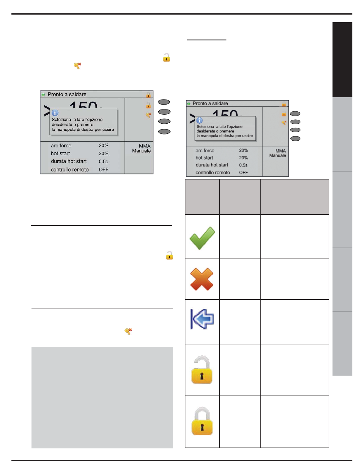
27
ESPAÑOL FRANÇAIS
DEUTSCH
ENGLISH
ITALIANO
3. Una volta confermata la password la
saldatrice riproporrà il messaggio in
Fig.C, una scritta Bloccato nella parte 1
del display e mostrerà le etichette Sblocca
e Reset pw. (reset password) associate
rispettivamente ai pulsanti 2 e 3 (fig.1) nella
parte 2 del display;
4. Per uscire dalla funzionalità di blocco
del punto di lavoro premere brevemente
la manopola 9 di fig.1;
5. Qualora si voglia procedere a
modificare il punto di lavoro salvato è
necessario attivare la funzione “Sblocca”
premendo il tasto funzione.
La funzione Sblocca richiede
l’inserimento della password che è stata
definita ed abilitata come sopra descritto.
6. La funzione reset password si attiva
premendo il tasto funzione (Reset pw).
ATTENZIONE:
la funzione Reset Password va utilizzata
qualora non si abbia tenuto traccia e non
ci si ricordi più la password di
Blocco/Sblocco impostata.
Per potere utilizzare questo tipo di
funzione è necessario contattare
direttamente il servizio di assistenza
tecnica FIMER.
Appendice:
etichette/icone dei pulsanti/tasti funzione
e pop-up informativi
Nella figura di seguito allegata e nella
successiva tabella sono descritte le principali
etichette/icone dei pulsanti/tasti funzione e i
pop-up informativi o relativi alle condizioni di
errore che possono comparire nelle zone del
display di seguito descritte:
Fig.C
Tasto F1
Tasto F2
Tasto F3
Tasto F4
Simbolo
Posizione
sul
display
Descrizione
Tasto F4
Nel caso in cui sia richiesto un inserimento dati da
parte dell’utente indica il
tasto da premere per confermare quanto inserito;
Tasto F3
Nel caso in cui sia richiesto un inserimento dati da
parte dell’utente indica il
tasto da premere per annullare l’operazione;
Tasto F1
Nel caso in cui sia richiesto un inserimento dati
da parte dell’utente indica il tasto da premere per
cancellare l’ultimo carattere inserito;
Tasto F1
Quando viene attivata la
funzionalità di gestione del
blocco della tastiera, tramite la manopola 10 (fig.1),
indica il tasto da premere
per disattivare il blocco.
Tasto F1
Quando viene attivata la
funzionalità di gestione
del blocco della tastiera,
tramite la manopola 10
(fig.1), indica il tasto da
premere per attivare il
blocco.
Page 32
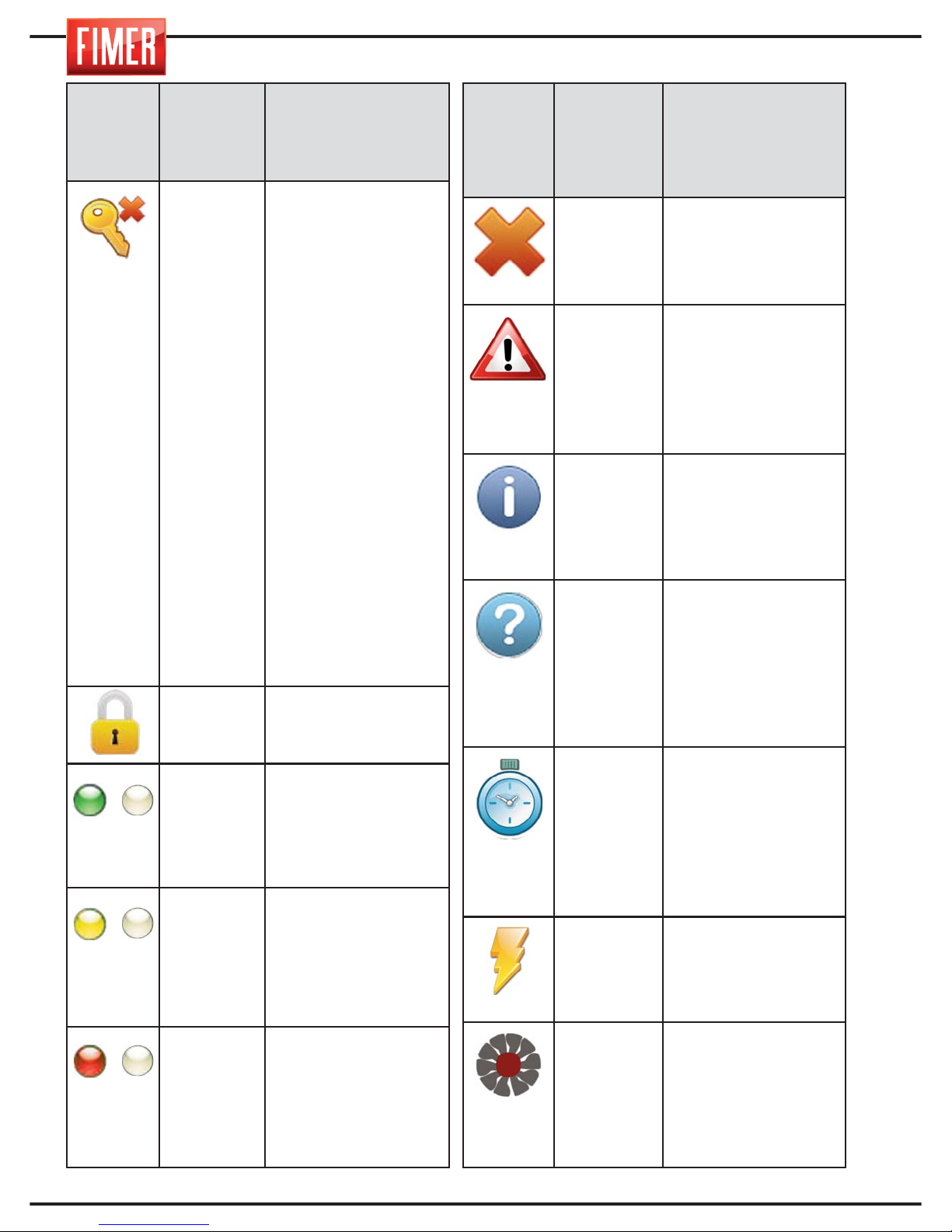
28
Simbolo
Posizione
sul
display
Descrizione
Tasto F2
Quando viene attivata la funzionalità di gestione del blocco della tastiera, tramite la
manopola 9 (fig.1), indica il
tasto da premere per effettuare l’operazione di eliminazione della password precedentemente memorizzata dall’utente (e permettere
così l’inserimento di una
nuova password); contemporaneamente all’operazione di eliminazione della
password precedentemente memorizzata, se è attivo
il blocco tastiera, viene effettuato lo sblocco.
ATTENZIONE: la funzione
Reset Password va utilizzata qualora non si abbia
tenuto traccia e non ci si
ricordi più la password
impostata. Per potere utilizzare questo tipo di funzione è necessario contattare direttamente il servizio di assistenza tecnica
FIMER.
(2)
Indica che il blocco
tastiera è attivo
(1)
Lampeggia con frequenza di 1Hz indicando che
l’applicazione è attiva; a
macchina in saldatura
indica che il duty-cycle
della stessa è compreso
nell’intervallo [60, 100]%
(1)
Lampeggia con frequenza di 1Hz indicando che
l’applicazione è attiva; a
macchina in saldatura
indica che il duty-cycle
della stessa è compreso
nell’intervallo [35, 60]%
(1)
Lampeggia con frequenza
di 1Hz indicando che l’applicazione è attiva; a macchina in saldatura indica
che il duty-cycle della
stessa è compreso nell’intervallo [0, 35]%
/
/
/
Simbolo
Posizione
sul
display
Descrizione
POP UP
Indica che il messaggio
riportato nel pop-up è
relativo ad un errore
che causa il blocco del
funzionamento della
macchina
POP UP
Indica che il messaggio
riportato nel pop-up è
relativo ad una operazione dell’utente in corso
sulla macchina alla quale
occorre prestare attenzione (es. caricamento filo o
spurgo gas)
POP UP
Indica che il messaggio
riportato nel pop-up è
informativo (es. visualizzazione versioni firmware/SD presenti a bordo
macchina)
POP UP
Indica che il messaggio
riportato nel pop-up
richiede un inserimento
dati da parte dell’utente
(es. inserimento nome
programma, inserimento
password di blocco/sblocco tastiera)
(1)
Sostituisce il led lampeggiante quando si effettua
il caricamento di un programma; una volta terminato il caricamento del
programma questo simbolo scompare e ritorna il
led lampeggiante
(2)
Sulle macchine dotate di
scheda HF indica l’attivazione continuativa di tale
scheda per un tempo
superiore a 0,5sec
(2)
Indica l’accensione delle
ventole di raffreddamento
sulle macchine che
abbiano le ventole attivabili da programma
Page 33
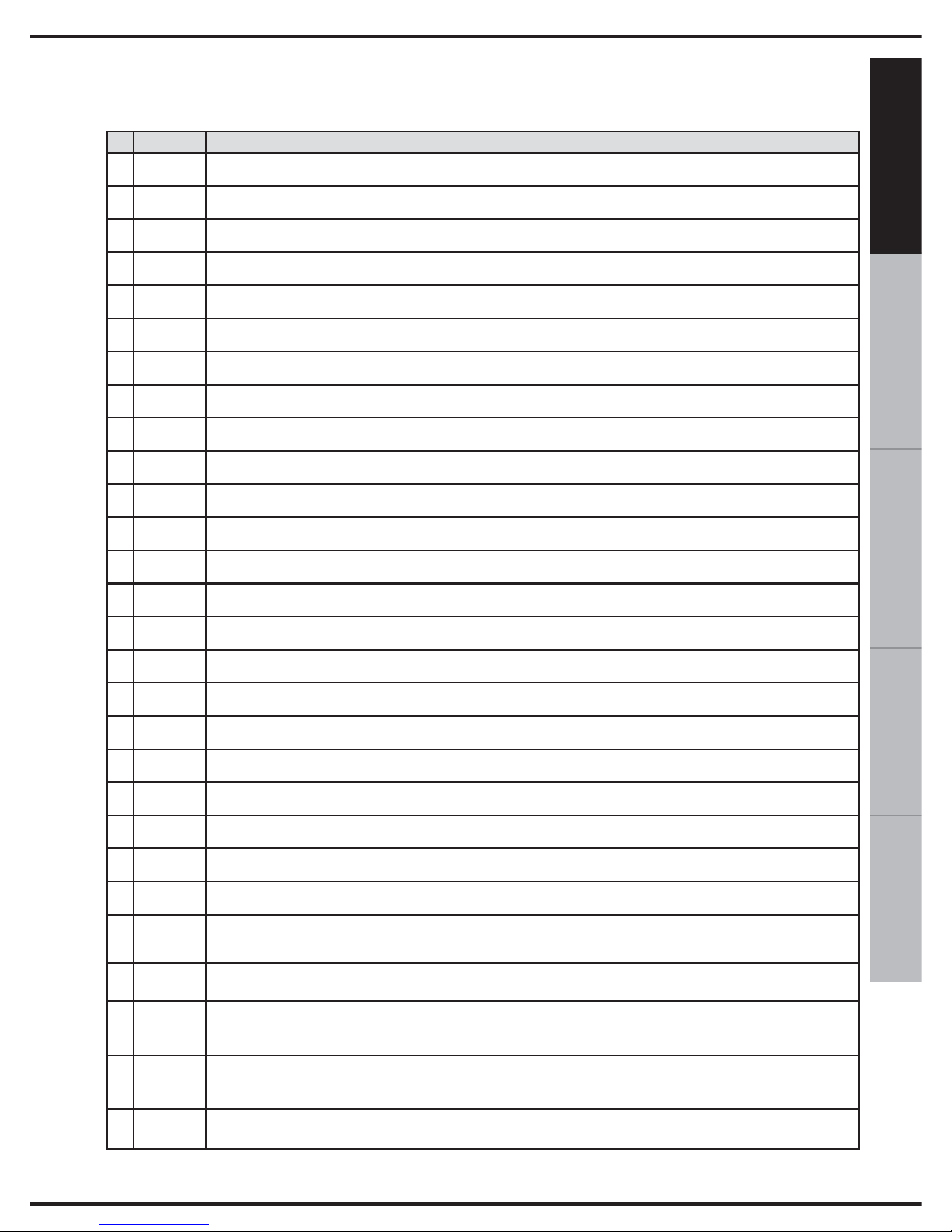
29
ESPAÑOL FRANÇAIS
DEUTSCH
ENGLISH
ITALIANO
E= error W= warning
23. CODICE ERRORI
Qui di seguito sono elencati gli errori che si possono incontrare e le relative descrizioni:
Codice
Descrizione
E 8101 Buffer dati non valido
E 8102 Errore durante la scrittura dati
E 8103 Indice/sottoindice CAN non valido
E 8104 Oggetto a sola lettura
E 8105 Errore durante la lettura dati
E 8106 Timeout durante scrittura dati
E 8107 Timeout durante lettura dati
E 8108 Dispositivo MMS non supportato
E 8109 Connessione dati interrotta
E 8201 Scheda SD non presente
E 8202 Scheda SD non formattata
E 8203 Errore durante la lettura dati da file
E 8206 File dati non presente
E 8209 Tabella sinergica non presente!
E 820c Richiesto aggiornamento SD!
E 8fa1 Creazione menu fallita
E 8fa2 Creazione gerarchia menu fallita
E 8fa3 Creazione parametri fallita
E 8fb1 Configurazione non corretta
W 4700
Caricamento filo manuale
Segnalazione che appare quando risulta premuto il pulsante di avanzamento
W 4701
Spurgo gas
Segnalazione che appare quando risulta premuto il pulsante di spurgo gas
E 9001
Antisticking
Segnalazione che appare quando l'uscita della macchina è in corto circuito, in modalità MMA o TIG
E 9002
Sovratemperatura inverter
Segnalazione che appare quando interviene la protezione hardware di temperatura del gruppo inverter
E 9003
Errore di rete
Segnalazione che appare quando la tensione di alimentazione eccede i limiti specificati o quando
mancano una o più fasi di alimentazione (solo macchine trifase)
E 9004
Sovraccarico termico
Segnalazione che appare quando la macchina ha superato il dutycycle di utilizzo dichiarato
E 9005
Bassa pressione acqua
Segnalazione che appare quando la pressione del liquido di raffreddamento è insufficiente, causa
mancanza del liquido stesso, presenza di bolle d'aria od occlusioni nel circuito di raffreddamento
E 9006
Sovratemperatura gruppo AC
Segnalazione che appare quando interviene la protezione hardware di temperatura del gruppo
per l'inversione di polarità
E 9010
Pulsante torcia premuto, rilasciare pulsante torcia e/o verificarne corretto funzionamento
Segnalazione che appare quando, all'accensione della macchina, risulti premuto il pulsante torcia
Page 34

30
SEGNALAZIONE
CAUSA/E
SOLUZIONI/CONSIGLI
Spegnimento della macchina
[display: spento]
Assenza di tensione sulla rete di alimentazione
Ripristinare la tensione di
alimentazione
24. RICERCA GUASTI
Qui di seguito sono elencati i più comuni problemi che si possono incontrare e le relative
soluzioni.
Errore di rete
1) Mancanza di una fase della rete
2) Sotto/sovratensione di rete
1) Controllare il collegamento alla
rete elettrica e verificare che i fusibili siano integri
2) Verificare che la rete abbia un
valore compreso fra 360Vrms e
440Vrms.
ANOMALIE DURANTE LA SALDATURA
[display:antisticking]
MMA: elettrodo in contatto con la massa
Allontanare l’elettrodo dal pezzo
Mancato innesco dell'arco
1) non sono collegati entrambi i cavi
(portapinza e massa)
2) i cavi sono interrotti
3) cattivo contatto tra pinza di massa
e pezzo
4) cattivo contatto tra pinza ed elettrodo
5) impostazione parametri di saldatura errata
6) la saldatrice non eroga corrente
1) controllare i collegamenti
2) controllare i cavi
3) controllare i collegamenti
4) controllare i collegamenti
5) controllare i parametri impostati
6) controllare la saldatrice
Cordone di saldatura poroso
Distanza e/o inclinazione sbagliata
della torcia
la distanza tra l'elettrodo ed il pezzo deve essere pari al diametro dell'anima dell'elttrodo stesso, circa,
per gli elettrodi basici la regola
L=diam. X 0.5, l'inclinazione non
deve essere eccessiva
Presenza di idrogeno dovuto dall'umidità nel rivestimento degli elettrodi, conservazione errata degli stessi
sostituire gli elettrodi,
conservare gli elettrodi secondo
istruzioni del costruttore/fornitore
Arco di saldatura troppo lungo
mantenere la corretta distanza
tra elettrodo e pezzo
Mancanza di fusione
1) parametri elettrici non corretti
2) velocità di saldatura troppo elevata
3) preparazione dei lembi sbagliata
4) posizione di saldatura errata
1) utilizzare i corretti parametri
diminuire la velocità
2) mantenere la corretta
posizione di saldatura
3) preparare correttamente il
giunto
(aprire l'angolo del cianfrino)
4) correggere la posizione di
saldatura
Incisioni marginali
1) parametri elettrici troppo elevati
2) posizione di saldatura errata
3) velocità di saldatura eccessiva
1) diminuire i parametri elettrici
2) correggere la posizione di saldatura
3) ridurre la velocità di saldatura
Page 35
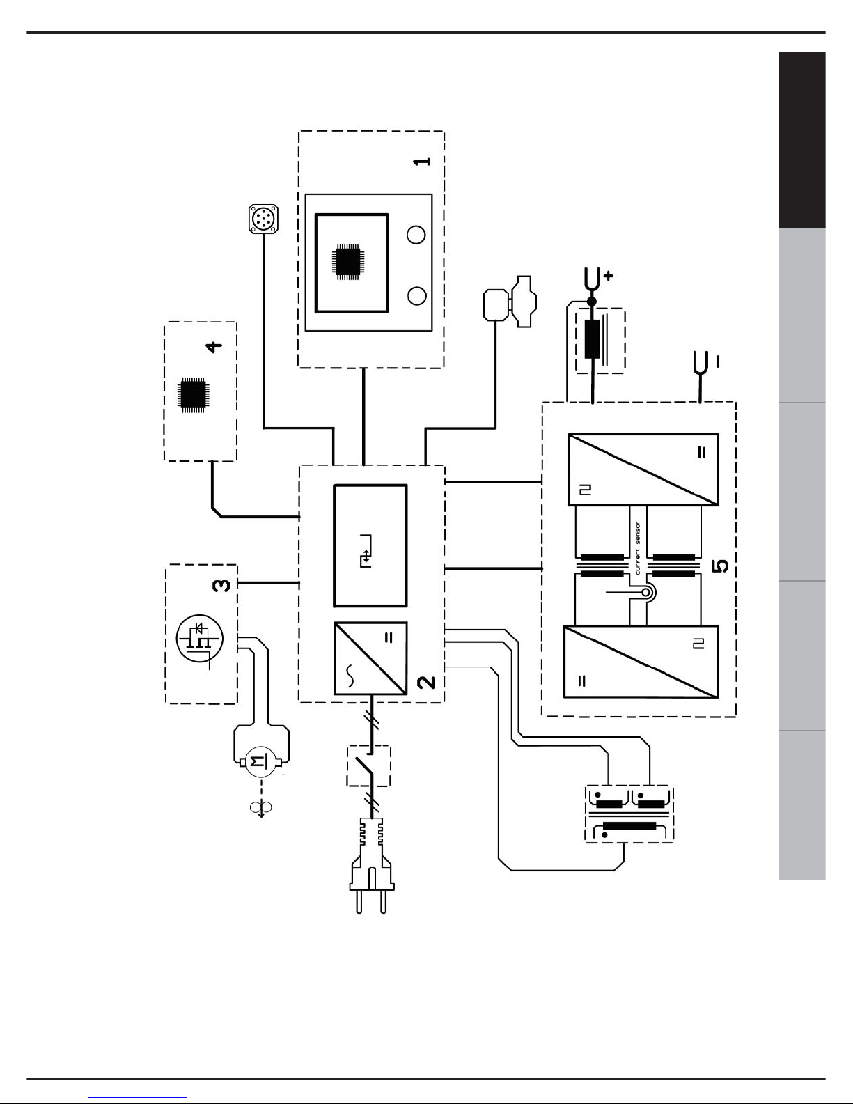
31
ESPAÑOL FRANÇAIS
DEUTSCH
ENGLISH
ITALIANO
25. SCHEMA BLOCCHI
1. Pannello di controllo
2. Scheda controllo di potenza
3. Scheda controllo motore
4. Scheda controllo di processo
5. Inverter di potenza
6. Trasformatore ausiliario
Page 36
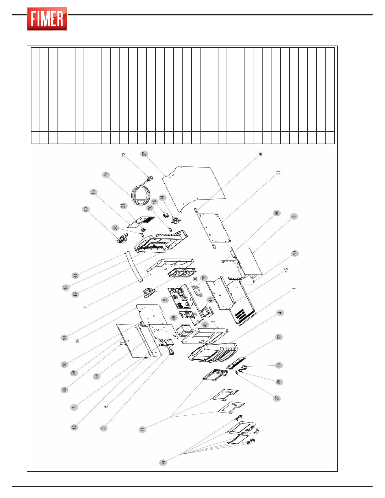
32
26. PARTI DI RICAMBIO
4
Frontale plastico parte superiore
5
Kit euroconnettore
7
Wire feeder
8
Scheda potenza
9
Scheda controllo
10
Aspo fissaggio bobina
12
Cerniera
13
Posteriore plastico parte superiore
14
Commutatore a camme 20A
15
Elettrovalvola
16
Pannello posteriore
19
Guscio parte inferiore
20
Portafusibile
21
Connettore 5 poli
22
Pannello potenza
23
Dinse
26
Connettore 7 poli
27
Connettore gas
31
Ventilatore
37
Cofano
38
Parete sinistra fissa
39
Parete mobile
40
Portamaniglia
41
Maniglia
42
Chiusura a slitta
47
Induttanza
48
Scheda Controllo motore
49
Trasformatore ausiliario
50
Convogliatore potenza
60
Staffa lexan per fissaggio dissipatori
70
Innesto rapido
71
Kit display
72
Cavo di linea
74
Kit cornice frontale
Page 37

1
ESPAÑOL FRANÇAIS
DEUTSCH
ENGLISH
ITALIANO
USER AND MAINTENANCE MANUAL
USER AND MAINTENANCE MANUAL
Fimer S.p.A. would like to thank you for choosing this machine; if used according to the
instructions reported in this user and maintenance manual, it will accompany you in your
work for many years without any problems.
This manual is an integral part of the machine and must accompany it whenever moved
or resold.
The user is responsible for making sure the machine is complete and in good working
order. The manufacturer has the right to make changes at any time, without notice.
Each Fimer product has been designed, built and made in Italy.
This is guarantee of maximum quality and reliability.
No part of this manual may be translated into another language, adapted or reproduced with any means (including
scanned documents, photocopies, film and microfilm) without the prior written consent of the manufacturer.
INDEX
INDEX
1. GENERAL SPECIFICATIONS AND NOTES FOR CONSULTING
THIS MANUAL .............................................................................. pag. 5
2. DESCRIPTION OF THE EQUIPMENT ............................................. pag. 5
3. LOADING THE WELDING WIRE................................................... pag. 8
4. MIG/MAG WELDING...................................................................... pag. 9
4. 1 Manual Short Arc MIG Welding ..................................................... pag. 9
4. 2 Synergic Short Arc MIG WELDING ................................................ pag. 11
4. 3 Pulse synergic MIG WELDING ....................................................... pag. 14
5. MIG WELDING CONECTOR............................................................. pag. 16
5.1 MIG TORCH.................................................................................. pag. 16
5. 2 CONNECTOR FOR MIG WELDING with a traditional torch............. pag. 16
5. 3 CONNECTOR FOR MIG WELDING with a Spool or Push-Pull torch ........ pag. 16
6. MIG ARC START............................................................................ pag. 17
7. ADJUSTING THE WELDER........................................................... pag. 17
8. HOW TO ACHIEVE THE BEST WELDING RESULTS............. pag. 17
9. MMA WELDING.............................................................................. pag. 18
9. 1 MMA WELDING Manual ................................................................. pag. 18
10 WELDING TABLE............................................................................. pag. 19
11 CONNECTION FOR MMA WELDING............................................... pag. 19
12. IGNITING THE MMA ARC ............................................................... pag. 19
13. TIG WELDING................................................................................ pag. 20
13. 1 TIG WELDING (Lift-Arc) ................................................................ pag. 21
14. CONNECTOR FOR TIG WELDING .................................................... pag. 23
15. POWER CONNECTOR................................................................... pag. 23
16. REMOTE CONNECTION ................................................................ pag. 23
16.1 REMOTE CONTROL OF THE WELDING CURRENT ....................... pag. 24
17. CONNECTING THE OUT-PUTS ...................................................... pag. 24
18. CONNECTING THE GAS CYLINDER AND THE GAS REGULATOR pag. 24
19. ORDINARY MACHINE MAINTENANCE.......................................... pag. 24
20. REPLACING THE WIREGUIDE SHEATH OF THE TORCH................ pag. 25
21. MEMORISING THE WORK POINT................................................... pag. 26
22. LOCKING A WORK POINT.............................................................. pag. 26
23. ERROR CODE................................................................................ pag. 29
24. TROUBLESHOOTING .................................................................... pag. 30
25. BLOCK DIAGRAM ......................................................................... pag. 31
26. SPARE PARTS .............................................................................. pag. 32
• CAUTION ......................................................................................... pag. 2, 3, 4
Page 38
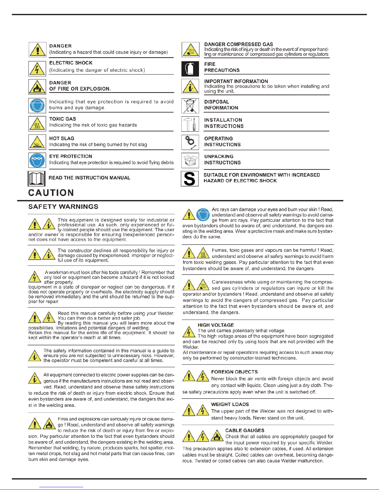
2
WARNING SYMBOLS
Page 39
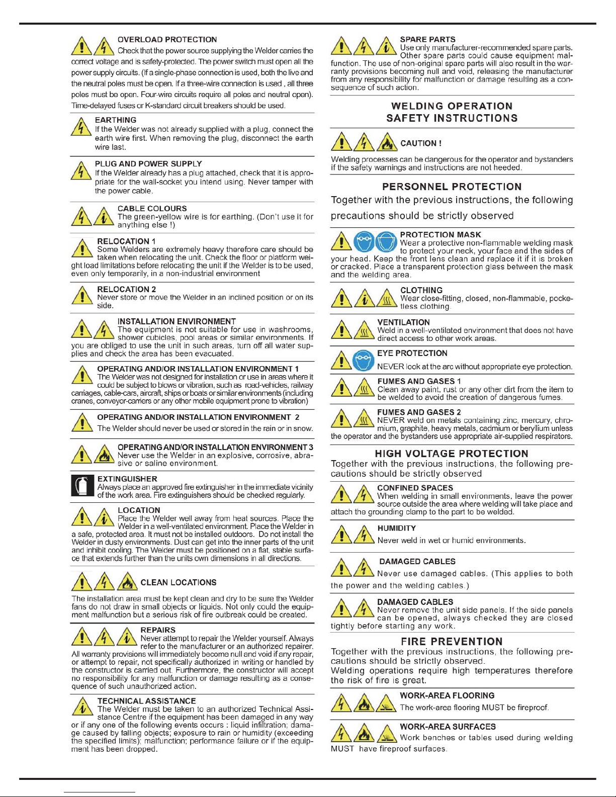
3
Page 40
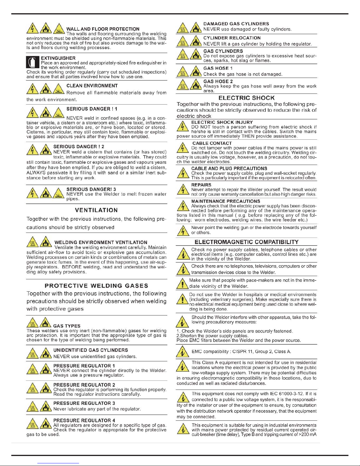
4
Page 41
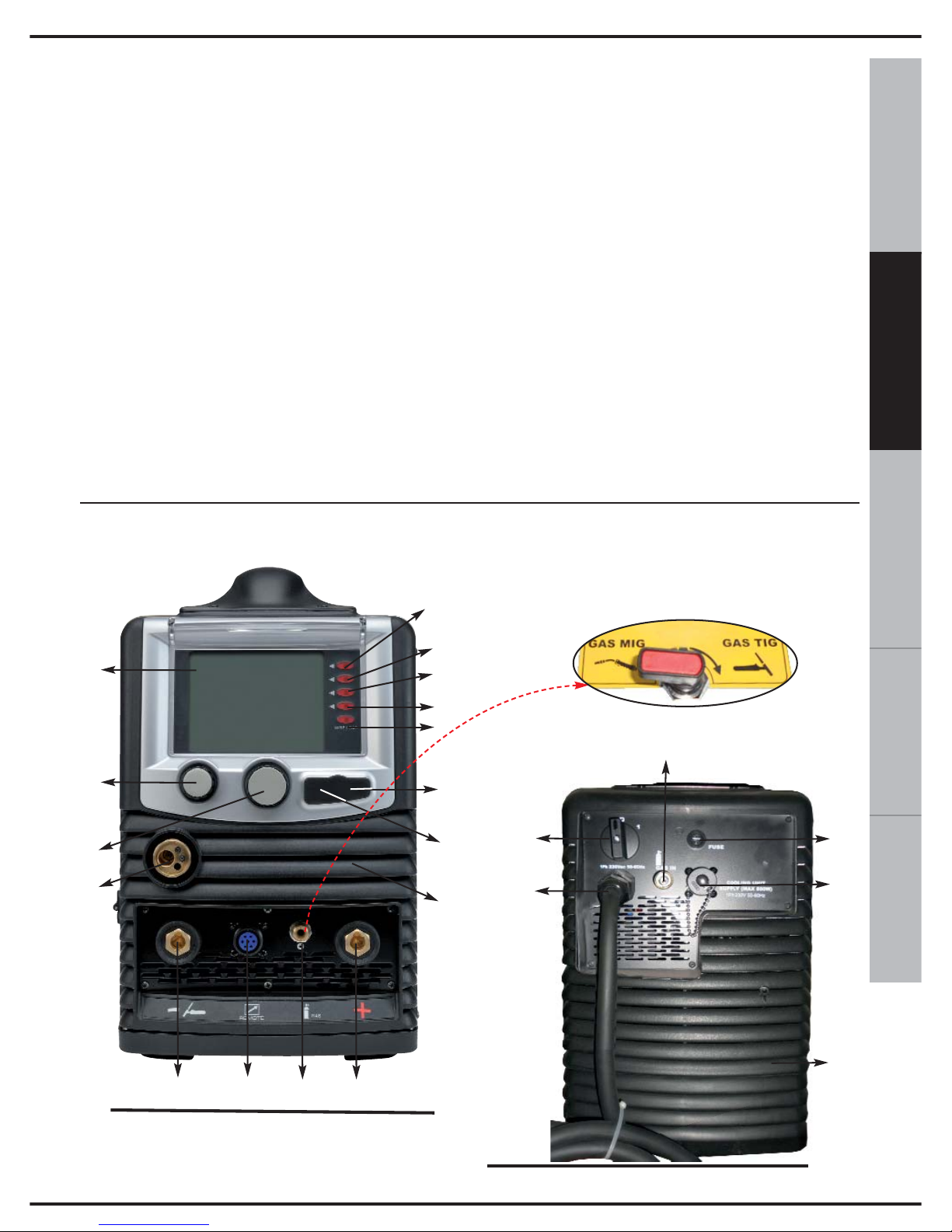
5
ESPAÑOL FRANÇAIS
DEUTSCH
ENGLISH
ITALIANO
1. GENERAL SPECIFICATIONS AND
NOTES FOR CONSULTING THIS MANUAL
The “TM236 EVO” welders are made using
INVERTER technology. They are extremely
compact and versatile devices that can be
used in all those situations that require
minimum obstruction, combined with the
highest performance.
These welders use both manual and synergic
MMA, TIG and MIG/MAG (short arc).
The innovative operator interface system, which
uses a large 5,7” TFT colour screen, allows for
simple and intuitive use of the equipment,
without renouncing on the possibility to
personalise all of the welding settings.
All of the main parameters of the machine
are stored on a memory card (SD-Card),
keeping the equipment constantly up-dated
with the latest welding developments. If the
memory card is removed the equipment will
cease to function, providing an optimal antitheft system and safeguard against
inappropriate use. Thanks to the advanced
control techniques adopted, the product is
extremely reliable and easy to use.
This instruction manual provides detailed
information on the machine settings: reading
the entire manual will allow you to appreciate
the extreme flexibility and practicality of use.
Caution: the device must only be used in the
manner and for the purpose described in this
manual. Never use inappropriately or for any
other purpose.
2. DESCRIPTION OF THE EQUIPMENT
Fig. 1
11
20
Fig. 2
17
19
18
1
2
3
4
5
6
10
9
16
12
14
15
13
11
7
8
I
N
T
E
R
N
A
L
T
A
P
21
using this selector you can
choose the gas outlet
dedicated for each
welding process
Page 42
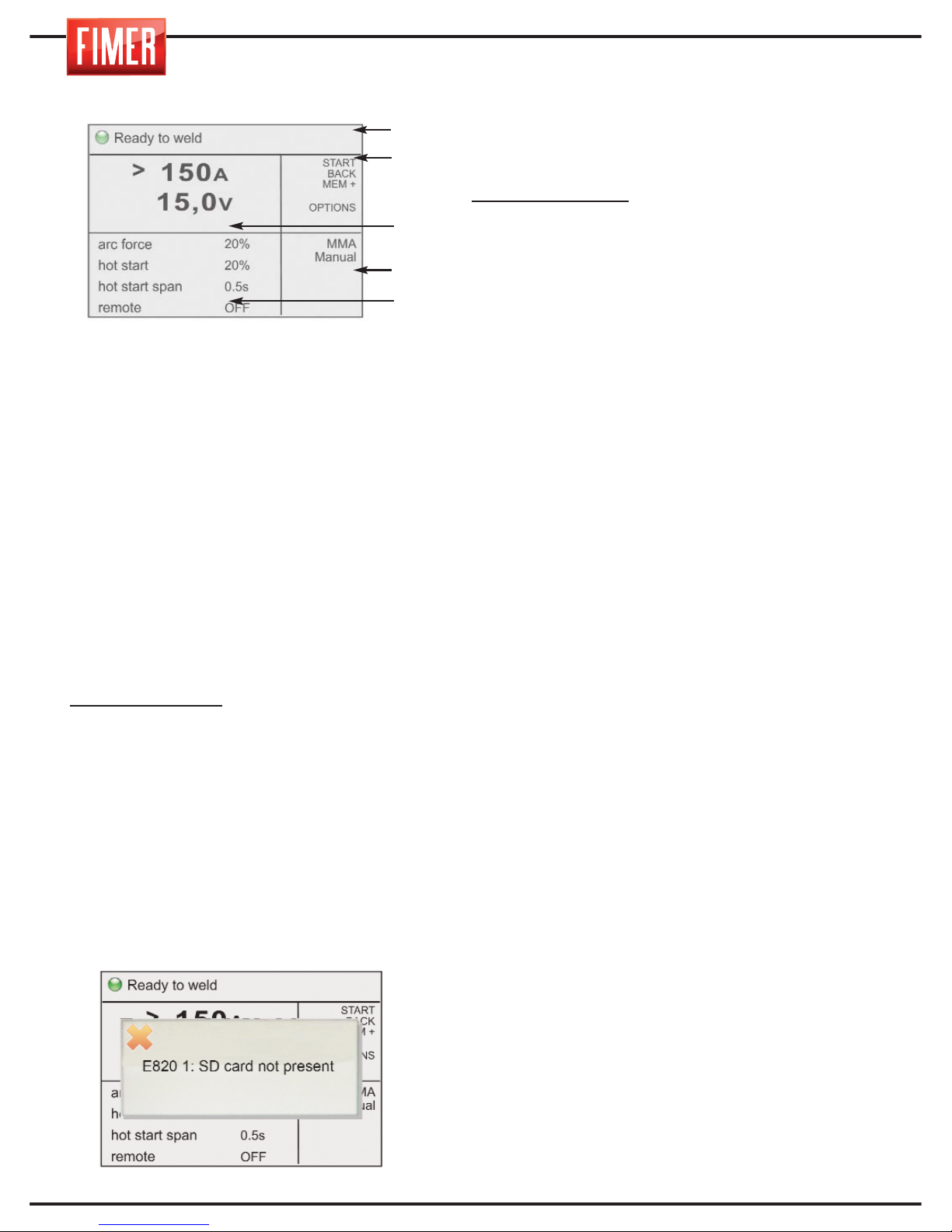
6
FIGURE 1:
1. Graphic display:
The 5,7’’ colour screen displays different
screens, according to the welding mode or
settings. In weld mode the display is divided
into five principal:
Part 1: Machine status
Part 2: Meaning of the active buttons
(buttons 2, 3, 4, 5,6 di fig.1)
Part 3: Size values set
Part 4: Type of process selected
Part 5: Indicates the values that can be set
for the various welding settings (to change
the values select using switch 10 and
confirm the selection by pressing the same
switch; the value will be highlighted in a
contrasting colour. The values can be
changed by turning the switch, to confirm
the new value press the switch again. 10).
Highlighted value:
Indicates the parameter
that is being changed using switch 10.
DISPLAYS:
- When the screen comes on, the Fimer logo
will appear and the Firmware revisions will load.
CONTROL BUTTONS:
(2, 3, 4, 5,6 in fig.1)
Each control button is associated with a
specific function shown on the display.
7. SD slot: this slot, covered with a rubber
cap, contains the SD-Card provided with the
machine; without the card, the machine will
be inactive and a warning message will
appear on the screen.
8. USB port: only for technical assistance.
9. Knob for setting the main welding
parameter: the main welding parameter can
be set with this knob:
Welding MMA/TIG:
sets the welding current.
11. Air grills (must never be obstructed).
12. “-” dinse front connector: negative
pole inlet.
Connection socket TIG torch mode.
MMA Mode: Ground clamp
MIG Mode: Ground clamp
13. Connector for remote control.
14. “+” dinse front connector: positive
pole inlet.
MMA Mode:Electrode holder
TIG Mode:Ground clamp
MIG Mode with gas: Not used
15. Gas Outlet:
MMA Mode: inactive
TIG Mode: Gas connection to the welding torch
(Internal tap positioned on TIG GAS)
MIG Mode with gas: inactive (internal tap
positioned on MIG GAS)
16. EUROCONNECTOR (SEPARATED
TROLLEY): quick connector for welding
torch. This connector is used to supply welding
gas to the torch, the electrical contacts of the
torch button and the welding current.
FIGURE 2:
17. ON-OFF switch: turns the machine on
and off.
18. Input cable: connection cable to the
mains power equipped.
19. Welding gas inlet
MMA Mode: Not used
TIG Mode: GAS connection to the cylinder
MIG Mode with gas: GAS connection to the
cylinder
20. Fuse
21.Connector for supplying power to the
liquid cooling system (Optional): Warning
the connector contains dangerous
voltages: NEVER use it for purposes other than
those for which it was specifically designed.
Part 1
Part 2
Part 3
Part 4
Part 5
Page 43
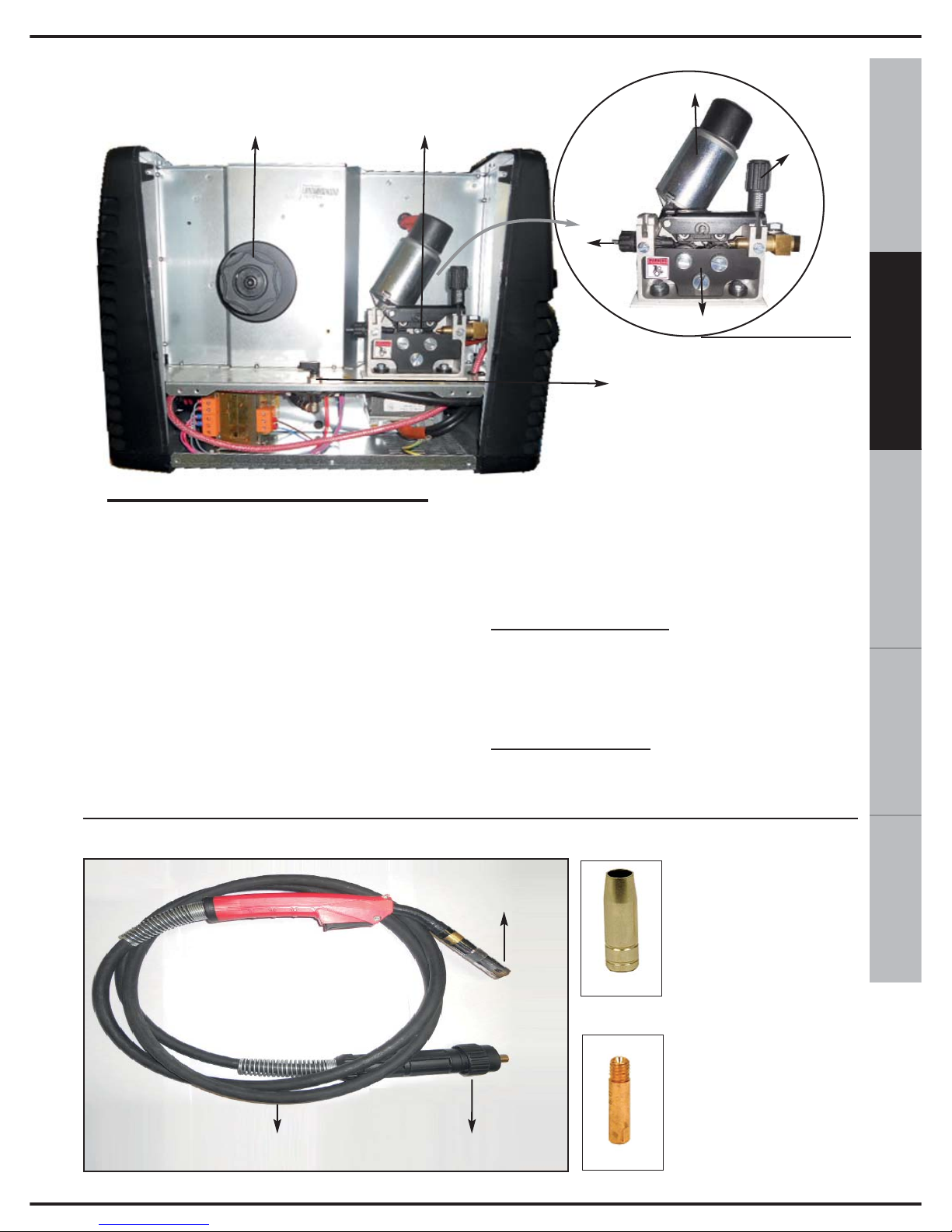
ITALIANO
ENGLISH
DEUTSCH
FRANÇAISESPAÑOL
7
22
23
24
26
25
27
28
FIGURE 3:
22. WIRE SPOOL SUPPORT
The 300mm MIG welding spool requires an
external support (cod. 580.727.001)
23. WIRE FEEDER SYSTEM: see figure 3A
for a more detailed image.
24. WIRE-FEEDER MOTOR
25. WIRE TENSION REGULATOR: Adjusts
the tension of the welding wire.
26. INLET OF THE WIRE FEEDER MOTOR
27. WIREFEEDER SPOOLS
28. GAS VALVE: The Gas Valve can be
rotated in three positions.
GAS MIG Position:
The tap feeds the
Euroconnector with the gas from the cylinder
connection (19) (For MIG with GAS
welding).
GAS TIG Position:
The tap feeds the front
connection (14) with the gas from the
cylinder connection (19) (For TIG welding).
Fig. 3
Fig. 3A
WELDING TORCH
Fig.4A
Fig.4B
GAS
NOZZLE
WIREFEEDER
TIP
TORCH BODY
CABLE
EUROCONNECTOR
Fig.4
Page 44
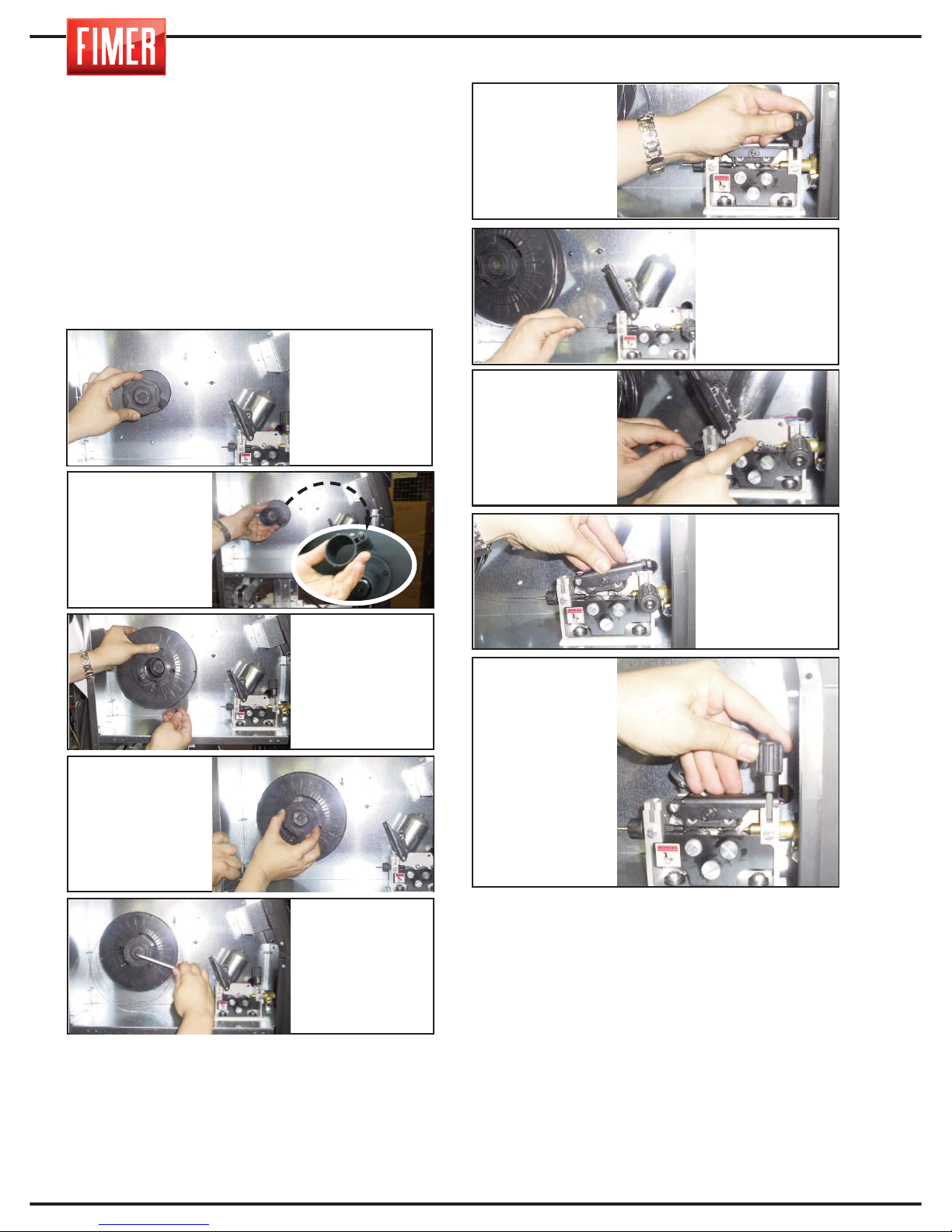
8
3. LOADING THE WELDING WIRE
To load the welding wire, follow these instructions carefully, in the order described below.
Warning: before inserting the wire, always
remove the gas nozzle (Fig. 4A) and the wire
feeder tip (Fig. 4B) from the welding torch.
1. Disconnect the cable from the power supply
(18 of Fig. 2).
Caution: before proceeding with the next step, make sure
the torch cable (Fig. 4) is well extended and that the welding wire does not have any bends or burrs. Failure to follow these precautions could damage the wire-feeding tube
inside the torch. Once the wire has been threaded through
the torch, attach the wire-feeder tip and the gas nozzle.
N.B. When changing the diameter of the wire, make sure
that the correct cable of the wire-feeder spool is facing
towards the inside of the machine. To do so, ensure that
the diameter and type of wire is legible (facing towards the
outside of the machine) Remember that the spools with a
‘V’ cable are suitable for feeding iron and steel wire. The
spools with a ‘U’ are suitable for aluminium wire.
Tighten or loosen the hex socket to set the correct tension: tightening too much can cause
excessive tension that could prevent the spool
from turning correctly. On the other hand, if the
tension is too loose, the welding wire could
accidentally unwind.
2. Unscrew the
ball-grip knob in
the centre of the
spool support of
the welding wire
(22 of Fig. 3).
7. Insert the wire
into the inlet tube
(26 of Fig. 3A)
of the wire feeder motor. .
9. Lower the
upper spools
4. Remove the
plastic wrap
from the new
spool and place
the spool on the
appropriate support (22 of Fig. 3).
5. Please note that
the hex socket
(M8) situated in the
centre of the spool
support is part of
the wire tension
system.
3. If necessary,
depending on
the size of the
spool used,
remove the
bearing spool.
4. Replace the
ball-grip knob.
6. Lower the roll
feeder (25 of Fig.
3A)
8. Run the wire
under the wire
feeder spools all
the way to the
out-let of the
Euroconnector.
10. Lift the knob
of plastic (25 of
Fig 3A) of the
pressure regulator of the wire.
Page 45
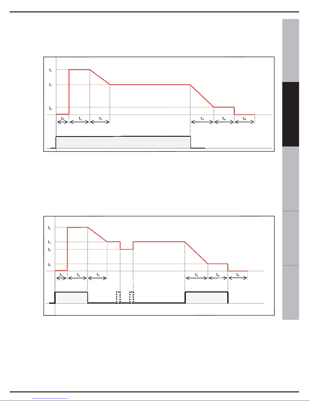
9
ESPAÑOL FRANÇAIS
DEUTSCH
ENGLISH
ITALIANO
In order to allow a better understanding of the welding parameters related to the MIG
mode, when necessary, refer to the following developments:.
t
2
: pre gas time
I
s
, t
s
: start current, start time
t
1
: l
s
->l
1
slope
I
1
: welding current
I
2
: current second level
t
4
: I
1
->I
e
slope
I
e
, t
e
: end current, end time
t
6
: post gas time
t
2
: pre gas time
I
s
, t
s
: start current, start time
t
1
: l
s
->l
1
slope
I
1
: welding current
I
2
: current second level
t
4
: I
1
->I
e
slope
I
e
, t
e
: end current, end time
t
6
: post gas time
Torch Button T.B.
4. MIG/MAG WELDING
Torch Button
MIG
2t mode with ramps
MIG 4t/4bi mode with ramps
Page 46
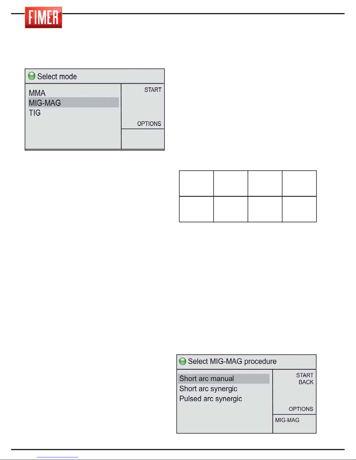
To select this welding mode :
To choose this welding mode use switch
10, select MIG and press confirm.
MIG/MAG welding (Metal Inert Gas and
Metal Active Gas) is continuous wire feed
welding that provides a higher current
density compared to welding with a flux-
covered electrode; this allows increased
penetration and speed and the joint can
be filled with less strokes.
Welding is carried out by melting a
metallic electrode, consisting of a
continuous wire, in a welding pool at a
constant speed, controlled by the welding
torch.
When the wire starts to feed, it touches the
area that requires welding, creating an
electric arc; the arc melts the wire, which
is then deposited on the workpiece.
This welder can be used with the following
types of wire:
1. solid wire: must always be used with a
gas shield.
2. Flux cored for gas welding: the centre of
the wire contains a mineral product that
improves the quality of the weld (this must
always be used with gas).
The correct method for connecting the torch
and the earth cable can be seen in the table
below:
Switch 9 adjusts the machine power.
There are two principal MIG-MAG welding
modes:
1.Manual short arc
2.Synergic short arc
3. Pulsed arc synergic
4.1 Manual Short Arc MIG Welding
By turning switch 10 it is possible to choose
from the different MIG-MAG welding modes;
press the switch to select the desired option.
WELDING
PROCESS
Euroconnettor
16 of Fig.1
‘+’
Front socket
14 of Fig.1
‘-’
Front socket
12 of Fig.1
MIG/MAG
TORCH
CABLE
NOT USED
EARTH
CABLE
10
Page 47
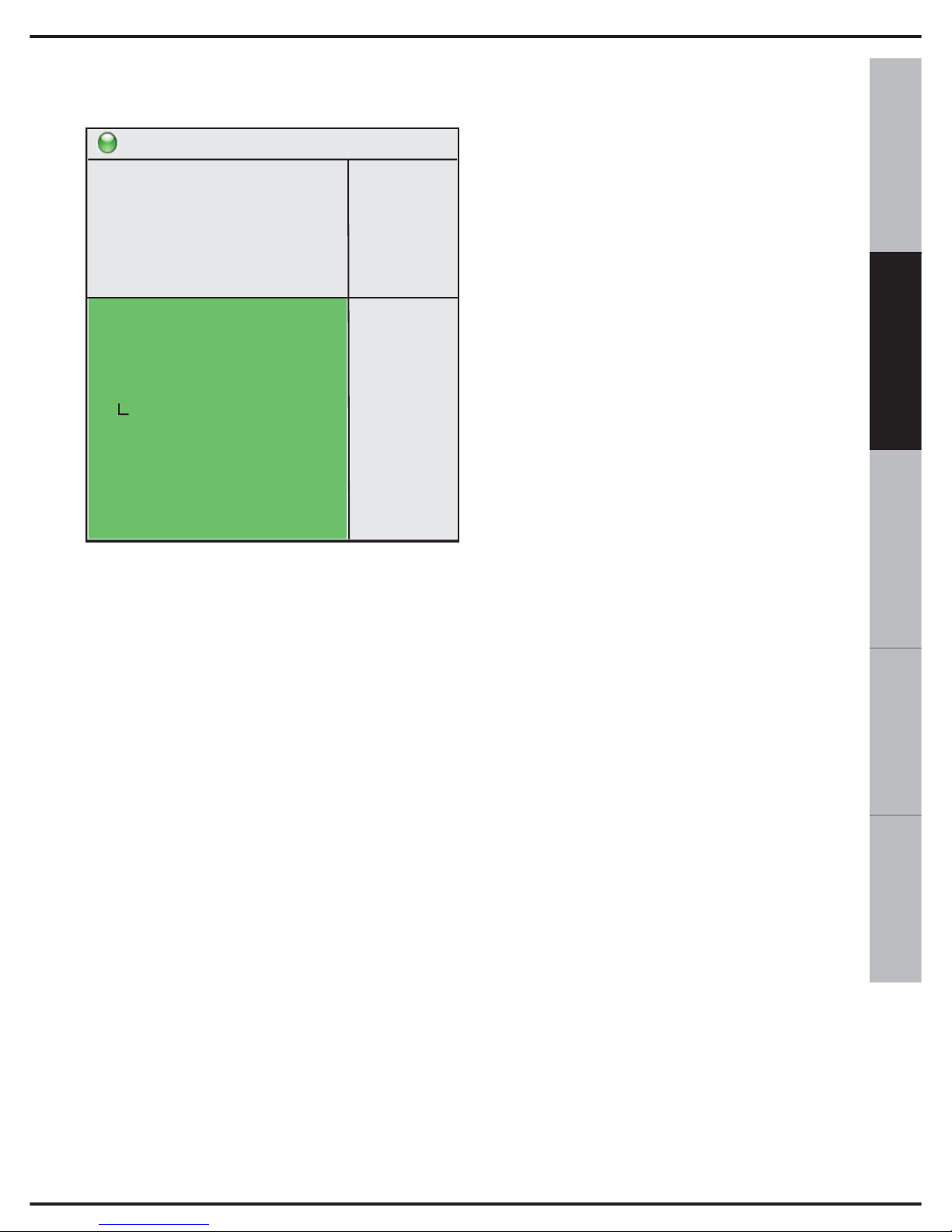
11
ESPAÑOL FRANÇAIS
DEUTSCH
ENGLISH
ITALIANO
Once selected the follow screen will appear:
ADJUSTMENTS AND SETTINGS:
Button 9 controls the current and the
machine power.
Button 10 adjusts the welding settings on the
screen:
Wire speed: Used to set the speed of the
welding wire.
Soft-start: Used to modify the speed at
which the wire approaches in order to obtain
a soft arc ignition; high values correspond to
low approach speeds.
Inductance: Used to modify the speed of
variation of the welding current to obtain a
harder arc (low values) or softer arc (high
values).
2t-4t-4bilevel: Used to set the operating
mode to 2 times or 4 times.
2t: In 2 time operating mode the machine
welds for the entire time the torch button is
held down.
4t: In 4 time operating mode pressing the
torch button once starts the weld and pres-
sing it a second time ends the weld.
Spot welding: Used to set (if other than 0)
the maximum duration of the weld.
Pause: Used to set (if other than 0) the dura-
tion of the pause between two successive
spot welds.
Pre gas time: Used to set the time for deli-
very of gas before striking the electric arc.
Post gas time: Used to set the time of
gas delivery after the welding current has
stopped.
Burnback: Used to vary the burnback time
of the wire at the end of the weld.
Hot start: Used to set the ignition current in
order to obtain a soft ignition; generally used
together with the Soft-start parameter.
Water pump: Used to switch on (ON) or
switch off (OFF) the water pump unit if pre-
sent.
4.2 Synergic Short Arc MIG WELDING
Synergic MIG welding allows the user to
easily adjust the weld settings, according to
the different materials that require welding.
During synergic welding, switch 9 of Fig 1
simultaneously adjusts the tension or the
speed of the wire. The other parameters
are automatically adjusted to the set power,
according to the diameter and type of wire
selected. The percentage of the length of
the arc can be varied using the ‘welding
tension’ setting. Welding quality can be
further improved by adjusting the ‘electronic
inductance’ and ‘deposit’ settings.
Ready to weld
START
BACK
MEM +
OPTIONS
150A
15,0V
>
MIG-MAG
S.A.M.
wire speed
soft start
inductance
2s-4s-4bilevel
spot welding
pause
pre gas time
post gas time
burnback
hot start
water pump
1,0 m/'
0
0
2t
0,0 s
0,0 s
0,1 s
2,0 s
2,0ms
0
OFF
2,8m/'
Page 48
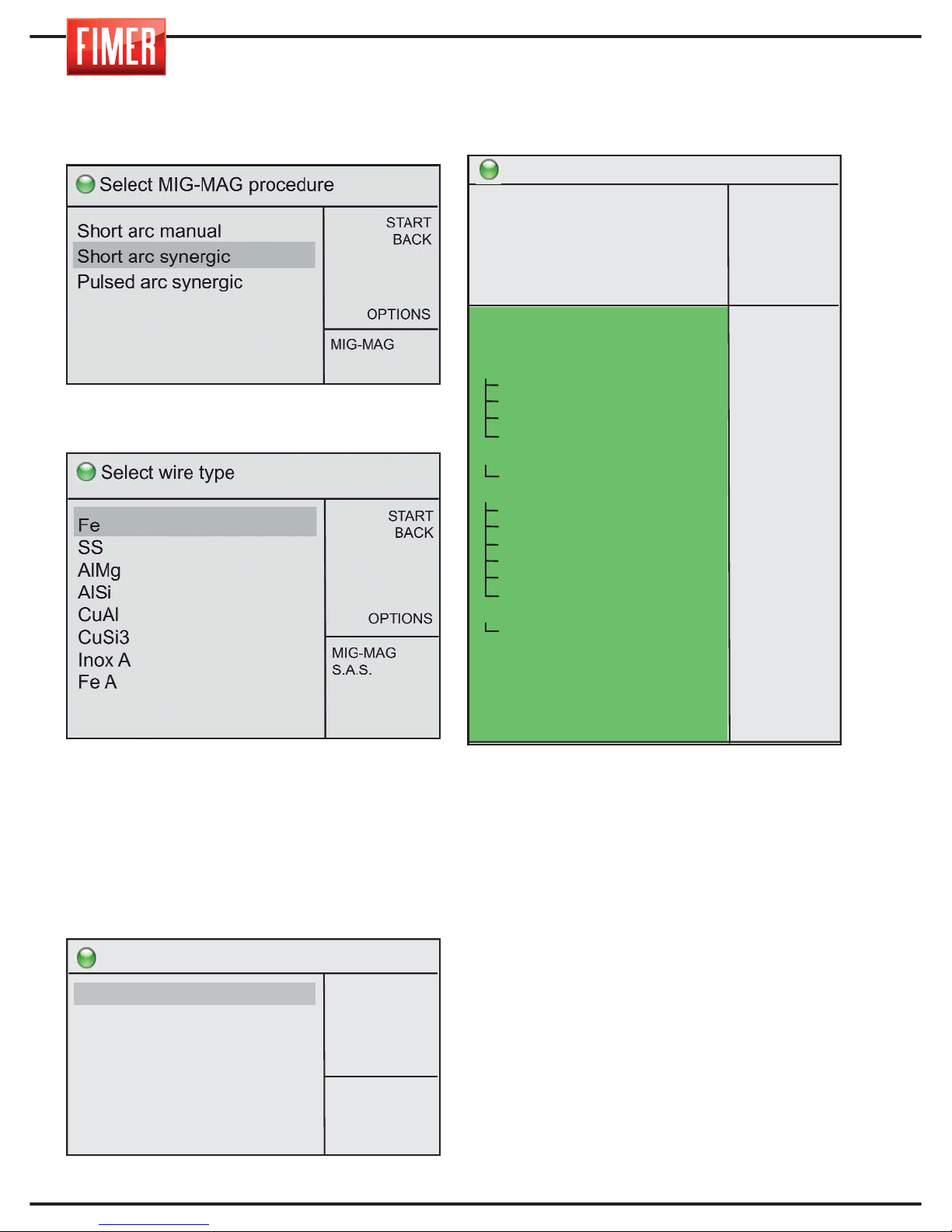
12
Turn switch 10 to choose from the different
MIG-MAG welding options; press the switch
again to confirm the chosen option.
Once selected, the screen with the welding
wire material options will appear:
Settings that do not appear on the screen
are accessible by turning switch 10.
Once the type of wire has been selected
(using switch 10), the settings page for the
welding wire diameter will appear.
Selecting this option will take you to the
welding screen:
ADJUSTMENTS AND SETTINGS:
Button 10 adjusts the welding settings on the
screen:
Arc length: Used to vary the basic voltage
used for welding.
Deposit: Used to modify the deposit of filler
material (wire speed) compared to the
predetermined synergic value.
Inductance: Used to modify the speed of
variation of the welding current to obtain a
harder arc (low values) or softer arc (high
values.
Double short: Used to activate (ON) or
START
BACK
OPTIONS
0,6mm
0,8mm
1,0mm
1,2mm
1,6mm
Select wire diameter
MIG-MAG
S.A.S.
Fe
Ready to weld
START
BACK
MEM +
OPTIONS
80A
23,2V
>
MIG-MAG
S.A.S.
Fe
0,6mm
arc lenght
deposit
inductance
double short
L1 span
L2 span
L2 amplitude
L2 voltage
2s-4s-4bilevel
2nd level
start/End level
Start level
Start level time
Ls->L1 slope
L1->Le slope
End level
End level time
spot welding
pause
pre gas time
post gas time
burnback
soft start
hot start
water pump
0,0v
0,0m/’
0
OFF
0,3s
0,3s
60%
0,0v
2t
80%
OFF
125%
0,0s
0,0s
0,0s
80%
0,0s
0,0s
0,0 s
0,1 s
2,0 s
0,0 s
0
0
OFF
10,5m/'
1,8mm
Page 49
13
ESPAÑOL
FRANÇAIS
DEUTSCH
ENGLISH
ITALIANO
Double short: Used to activate (ON) or
deactivate (OFF) the mode at two levels, in
other words the continual switching between
two different levels of welding current
L1 span: When the two level mode is active
this function is used to set the duration of the
first current level.
L2 span: When the two level mode is active
this function is used to set the duration of the
first current level.
L2 amplitude: When the two level mode is
active this function is used to set the second
current level (L2) compared to the current set
(level L1)
L2 voltage: When the two level mode is
active this function is used to modify the
voltage of the second level (L2)
independently of the voltage of the L1 level
(arc length parameter)
2t-4t-4bilevel: Used to set the operating
mode to 2 times or 4 times.
2t: In 2 time operating mode the machine
welds for the entire time the torch button is
held down.
4t: In 4 time operating mode pressing the
torch button once starts the weld and
pressing it a second time ends the weld.
4bi: This operation is similar to the 4t mode
with the only difference that pressing the
torch button for short periods (< 1s) during
welding causes the passage of the current
from the first level I1 to the second level I2;
holding the button down (> 1s) causes the
start of the end of the weld.
2nd level: used to set the value of the
current relative to the second power level,
active when the value of the 2t-4t-4bilevel
parameter is set to 4bi.
Start/End level: Used to activate (ON) or
deactivate (OFF) the mode with the initial
and final current.
Start level: Used to set the initial value as a
percentage of the welding current (e.g. 130%
implies Is=1,30xI1)
Start level time: Used in 2t mode to set the
time the initial current ls is applied
Ls->l1 slope: Used to set the duration of the
current ramp from the initial level Is to the
welding current I1.
L1->le slope: Used to set the duration of the
current ramp from the welding current I1 to
the final level Ie.
End level: Used to set the final current as a
percentage of the welding current (e.g. 80%
implies If=0.80xI1)
End level time: Used in 2t mode to set the
time of application of the final current If
Spot welding: Used to set (if other than 0)
the maximum duration of the weld.
Pause: Used to set (if other than 0) the
duration of the pause between two
successive spot welds.
Pre-gas time: Used to set the time for
delivery of gas before striking the electric arc.
Post-gas time: Used to set the time of gas
delivery after the welding current has
stopped.
Burnback: Used to vary the burnback time
of the wire at the end of the weld.
Soft start: Used to modify the speed at
which the wire approaches in order to obtain
a soft arc ignition; high values correspond to
low approach speeds.
Hot start: Used to set the ignition current in
order to obtain a soft ignition; generally used
together with the Soft-start parameter.
Water pump: Used to switch on (ON) or
switch off (OFF) the water pump unit if
present.
Page 50
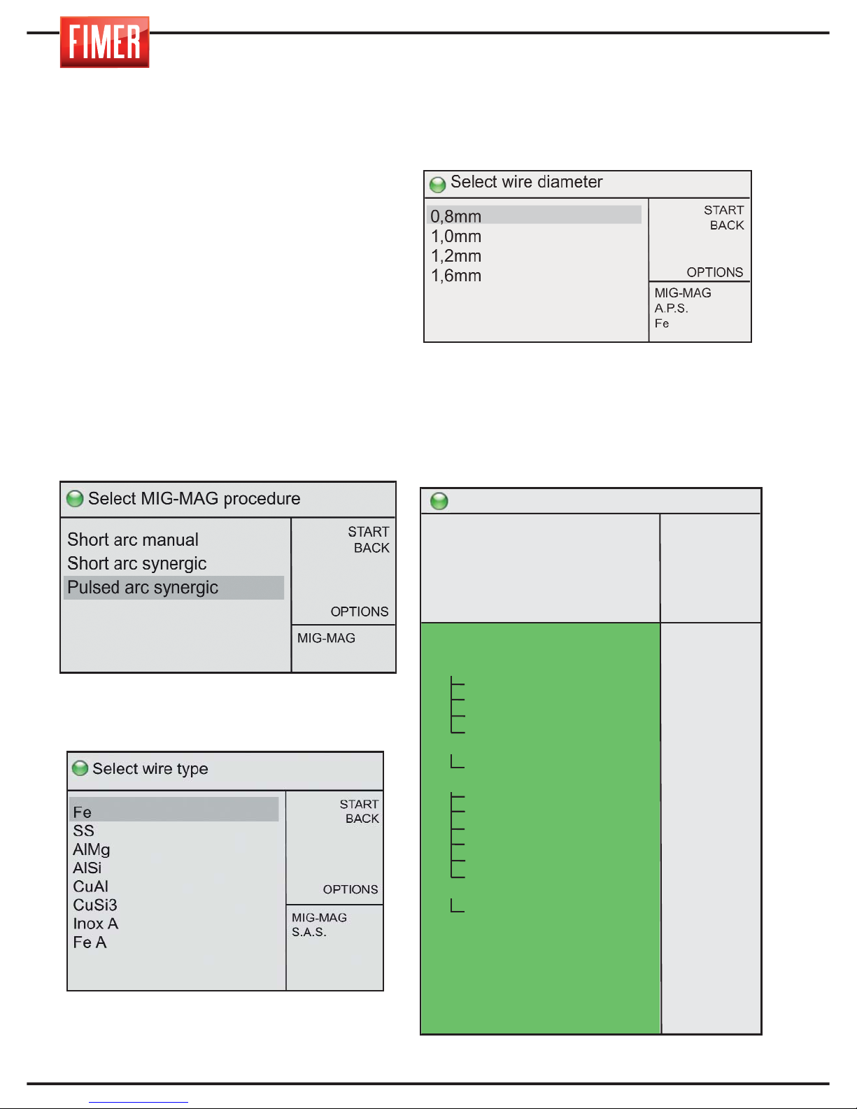
14
4.3 Pulse synergic MIG WELDING
Pulse synergic MIG welding allows obtaining
a relatively cold welding bead and good
penetration.
The low energy input makes this welding
process particularly suitable for thin layers
and for materials such as stainless steel and
aluminium.
During welding with synergic adjustment, the
wire speed (i.e. welding power) can be
adjusted with knob 9 shown in Fig.1.
The other parameters are automatically
adjusted to the set power depending on the
type and diameter of the wire selected.
By turning switch 10 it is possible to choose
from the different MIG-MAG welding modes;
press the switch to select the desired option.
Once selected, the screen with the welding
wire material options will appear:
Settings that do not appear on the screen
are accessible by turning switch 10.
Once the type of wire has been selected
(using switch 10), the settings page for the
welding wire diameter will appear.
The wire’s diameters could not be available
for all models.
Selecting this option will take you to the
welding screen:
Ready to weld
START
BACK
MEM +
OPTIONS
150A
30,7V
>
MIG-MAG
A.P.S.
Fe
0,8mm
arc lenght
deposit
double pulse
L1 span
L2 span
L2 amplitude
L2 arc length
2s-4s-4bilevel
2nd level
start/End level
Start level
Start level time
Ls->L1 slope
L1->Lf slope
End level
End level time
spot welding
pause
pre gas time
post gas time
burnback
soft-start
hot start
inductance
water pump
0,0v
0,0m/’
OFF
0,3s
0,3s
60%
0,0v
2t
80%
OFF
125%
0,0s
0,0s
0,0s
80%
0,0s
0,0s
0,0s
0,1 s
2,0 s
0,0
0
0
0
OFF
14,8m/'
5,0mm
Page 51
15
ESPAÑOL FRANÇAIS
DEUTSCH
ENGLISH
ITALIANO
Arc length: Used to vary the basic voltage
used for welding.
Deposit: Used to modify the deposit of filler
material (wire speed) compared to the predetermined synergic value.
Double pulse: Used to activate (ON) or
deactivate (OFF) the mode at two levels, in
other words the continual switching between
two different welding current levels.
L1 span: When the two level mode is active
this function is used to set the duration of the
first current level.
L2 span: When the two level mode is active
this function is used to set the duration of the
first current level.
L2 amplitude: When the two level mode is
active this function is used to set the second
level current (L2) compared to the current
set (L2l)
L2 arc length: When the two level mode is
active this function is used to modify the arc
length of the second level (L2) independently
of the arc length of level L1 (arc length
parameter)
2s: In 2 time operating mode the machine
welds for the entire time the torch button is
held down.
4s In 4 time operating mode pressing the
torch button once starts the weld and pressing it a second time ends the weld.
4bi: This operation is similar to the 4t mode
with the only difference that pressing the
torch button for short periods (< 1s) during
welding causes the passage of the current
from the first level I1 to the second level I2;
holding the button down (> 1s) causes the
start of the end of the weld
2nd level: Used to set the value of the
current relative to the second power level,
active when the value of the 2t-4t-4bilevel
parameter is set to 4bi.
start/End level: Used to activate (ON) or
deactivate (OFF) the mode with the initial
and final current.
Start level: Used to set the initial value as a
percentage of the welding current (e.g. 130%
implies Is=1,30xI1).
Start level time: Used in 2t mode to set the
time the initial current ls is applied
Ls->L1 slope: Used to set the duration of
the current ramp from the initial level Is to the
welding current I1.
L1->Lf slope: Used to set the duration of the
current ramp from the welding current I1 to
the final level If.
End level: Used to set the final current as a
percentage of the welding current (e.g. 80%
implies If=0.80xI1).
End level time: Used in 2t mode to set the
time of application of the final current If.
Spot welding: Used to set (if other than 0)
the maximum duration of the weld.
Pause: Used to set (if other than 0) the duration of the pause between two successive
spot welds..
Pre gas time: Used to set the time for
delivery of gas before striking the electric arc.
Post gas time: Used to set the time of gas
delivery after the welding current has
stopped.
Burnback: Used to vary the burnback time
of the wire at the end of the weld.
Soft-start: Used to modify the speed at
which the wire approaches in order to obtain
a soft arc ignition; high values correspond to
low approach speeds.
Hot start: Used to set the ignition current in
order to obtain a soft ignition; generally used
together with the Soft-start parameter.
Inductance: Used to modify the speed of
variation of the welding current to obtain a
harder arc (low values) or softer arc (high
values).
Water pump: Used to switch on (ON) or
switch off (OFF) the water pump unit if present.
Page 52
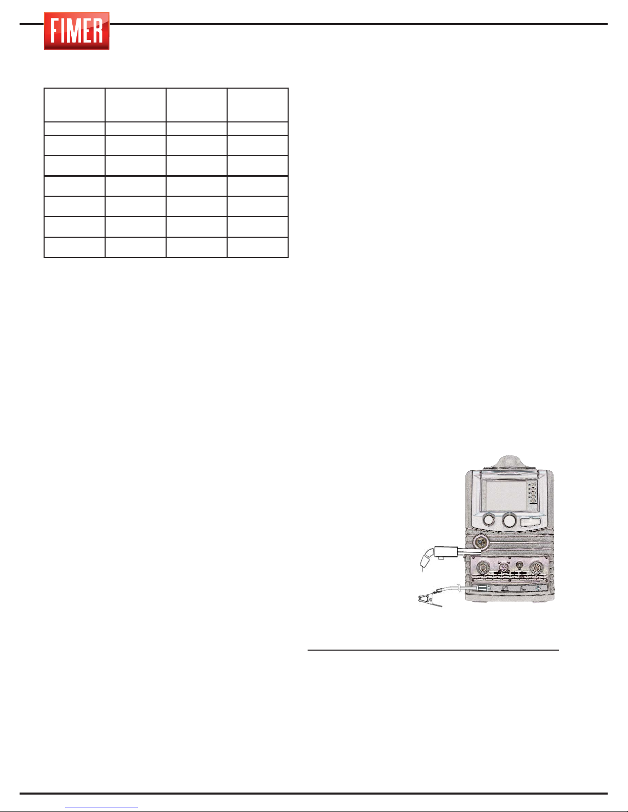
16
Please refer to the following table for the
correct welding current settings:
5. MIG WELDING CONECTOR
The connector for the welding cables comes
with a quick connect system that uses
appropriate connectors.
5.1. MIG TORCH
We would advise you to carry out regular
controls on the condition of the welding
torch; in particular, always check the nozzle/gas blowpipe (Fig. 4A) the wire feeder tip
(Fig. 4B), and the internal sheath of the
torch. These parts must be kept well-cleaned
and intact. If the wire stops threading correctly. replace the wire guide.
N.B. Each wire and diameter corresponds
to an appropriate wire feeder tip and
sheath. Always make sure you are using
the correct type.
5.2 CONNECTOR FOR MIG WELDING
with a traditional torch
1) Connect the earth cable to the appropriate
‘-‘ socket on the front of the device (12 of Fig 1).
Insert the connector by lining up the key with
the groove and turn in a clockwise direction
until it stops. Do not fasten too tightly!
2) Connect the torch to the appropriate
socket in the front of the device (16 di Fig 1),
turning the connector in a clockwise direction
until it stops. Do not fasten too tightly!
Warning: the machine is provided with
sockets for the MIG welding torch (Fig 4) This
accessory has a long life-time if periodical
controls of the gas nozzle and the wirefeeder tip are carried out (Fig 4A) (Fig 4B).
These parts must be kept well-cleaned and
intact. Replace the wire guide when the wire
no longer threads correctly.
5.3 CONNECTOR FOR MIG WELDING
with a Spool or Push-Pull torch
1) Connect the earth cable to the appropriate ‘-‘
socket. (12 of figure 1). Insert by lining up the
key with the groove and turn in a clockwise
direction until it stops. Do not fasten too tightly!
2) Connect the torch to the appropriate socket
on the front of the device (16 of Fig 1),
turning in a clockwise direction until it stops.
Do not fasten too tightly!
3) Insert the connector of the torch into the
appropriate female socket.
MIG WELDING:
Connect the pressure regulator to the cylinder, after which attach the gas tube of the
torch to the latter.
MIG welding is usually carried out with a
constant current, with
a positive pole (“+
“see fig.5).
The MIG torch cable
is connected to the
Euroconnector (16
of fig.1), whilst the
earth cable of the
workpiece is connected to the ‘-‘
socket on the front
(12 di fig.1).
At this stage adjust the welding current using
the potentiometer (9 of Fig.1), situated on the
front panel.
The diameter of the electrode and the wel-
ding current settings must be selected accor-
ding to the thickness of the workpiece.
WORKPIECE
THICKNESS
WIRE
DIAMETER
WELDING
CURRENT
ARC
mm mm A
0.8 - 1.0 0.6 - 0.8 60-100
Short-Arc
1.5 - 2.0 0.8 - 1.0 80-120
Short-Arc
2.0 - 3.0 1.0 - 1.2 100-130
Short-Arc
3.0 - 4.0 1.2 120-200
Short-Arc
> 4.0 1 150÷200
Spray-Arc
> 4.0 1.2 200÷300
Spray-Arc
Fig.5
Page 53
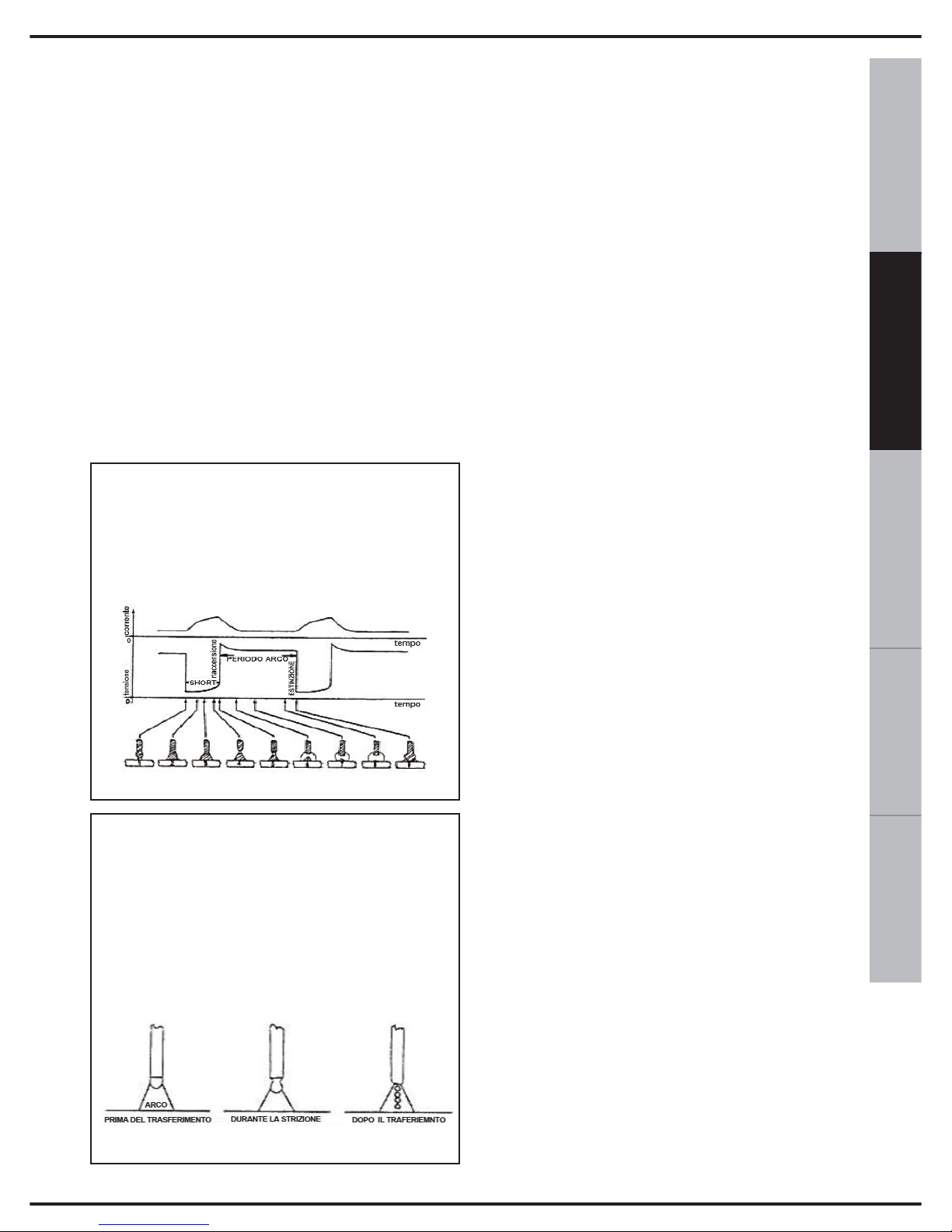
17
ESPAÑOL FRANÇAIS
DEUTSCH
ENGLISH
ITALIANO
6. STRIKING AN ARC IN
MIG WELDING
The MIG-MAG welding process is when an
electric arc is created between a consuma-
ble wire and the workpiece, protected within
a gas atmosphere. This atmosphere can be
either inert (Argon) or active (CO2 or a mix-
ture of Argon and CO2).
The wire is continuously fed through a torch
by a wire feeder to the weld pool. A solid wire
or flux-cored wire can be used.
The transfer methods of the filler material defi-
ne different arc types:
- the tension directly influences the appearance of the welding seam, but the dimensions of the welding surface can be varied,
according to requirements, by manual movement of the torch to obtain variable deposits
with a constant tension.
- the speed of the movement of the wire is
in relation to the welding current.
7. ADJUSTING THE WELDER
Once the welding tension has been set,
maintain the length of the electric arc between
5 and 10 mm and adjust the wire speed to
achieve the best welding results. Initially,
carry out a welding test on a well-cleaned
sample, free of any coating, rust or paint.
NOTE The torch trigger controls the following
functions:
- gas flow
- wire movement
- welding current
8. HOW TO ACHIEVE THE BEST
WELDING RESULTS
1. Hold the torch at an angle of 45° from the
workpiece. Keep the gas nozzle (Fig. 4A) at
a distance of approximately 6 mm from the
workpiece.
2. Move the torch with a continuous movement, using a push, not pull, motion. This will
guarantee the gaseous shield of the arc.
3. Avoid welding in high winds.
If the wind is too strong it could carry the gas
away from the welding pool, creating a porous
(weak) weld.
4. Keep the wire clean: never use rusty wire.
5. Make sure the torch cable is free of dents
or coils, which could compromise the correct
movement of the wire.
6. When changing the wire spool, always clean
the wire feed tube with compressed air.
SHORT ARC (short-circuit transfer):
this brings the electrode into direct contact with the weld pool, which creates a
short-circuit that extinguishes the arc,
after which the arc reignites and the cycle
is repeated.
SPRAY ARC (spray transfer):
this allows the droplets to detach from the
tip of the electrode, which successively reach the weld pool.
The fact the arc is visible, reduces the need
for the operator to strictly observe the adjustment tables, allowing for direct control of the
welding pool.
Page 54
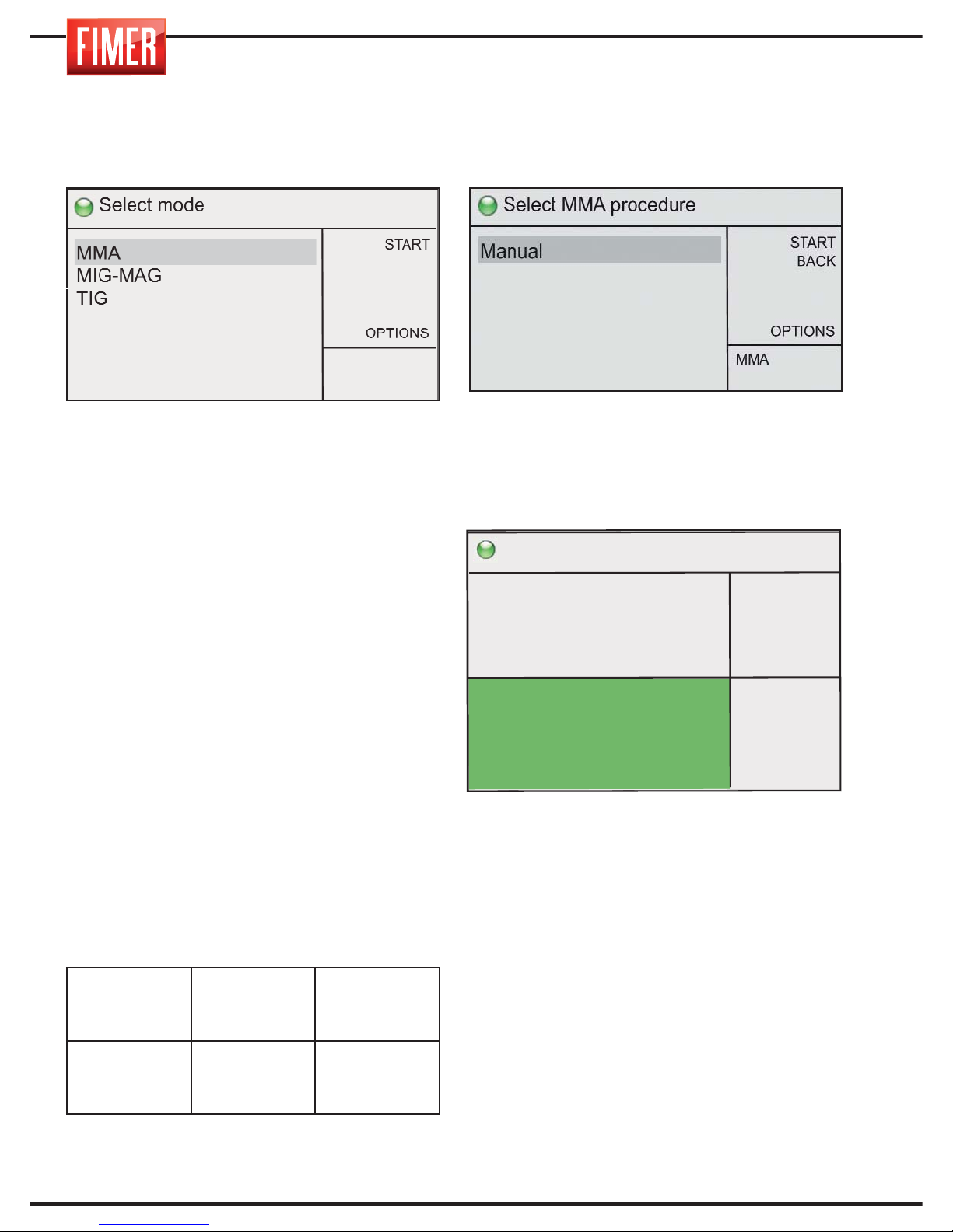
18
9. MMA WELDING
To select this welding mode, use switch 10,
select MMA and press confirm.
Electric arc welding with a covered MMA
(Metal Manual Arc) electrode or SMAW
(Shielded Metal Arc Welding) is a manual
welding procedure that takes advantage of
the heat generated by the electric arc, which
strikes between a covered earthed electrode
and the workpiece. This procedure allows for
the creation of joints in any position, in the
workshop, outdoors, in confined areas or
places that are difficult to access.
With the TM 236 it is possible to weld any
type of electrode and diameter. The spark of
the arc occurs by placing the electrode close
to the workpiece.
The correct connection of the electrode
clamp holder and the earth cable can be
seen in the table below:
Always make sure that the earth and the
electrode clamp holder are kept far apart.
9.1 MMA WELDING Manual
This mode can be accessed using switch 10.
Selecting this option will take you to the
welding screen:
Switch 9 in fig. 1 adjusts the welding current
(very thick workpieces require a higher
current).
Furthermore, switch 10 adjusts the
parameters shown in the figure below:
ADJUSTMENTS AND SETTINGS:
Button 10 adjusts the welding settings on the
screen:
Arc Force: Used to set the increase in current
as a percentage of
the welding current, which the welder can
provide to keep the arc fully ignited.
Hot start: Used to set the current increase as
a percentage of the welding current, which the
welder can provide at the time the arc is struck.
Hot start span: Used to set the time during
which the hot start current is provided.
Remote ctrl: Used to switch on (ON) or switch
off (OFF) the remote control of the intensity of
the current delivered.
WELDING
PROCESS
Front Socket
+
14 di Fig.1
Front Socket
-
12 di Fig.1
MMA
ELECTRODE
CLAMP HOLDER
EARTH CABLE
Ready to weld
START
BACK
MEM +
OPTIONS
arc force
hot start
hot start span
remote ctrl
20%
20%
0.5s
OFF
MMA
Manual
150
A
15,0V
>
Page 55
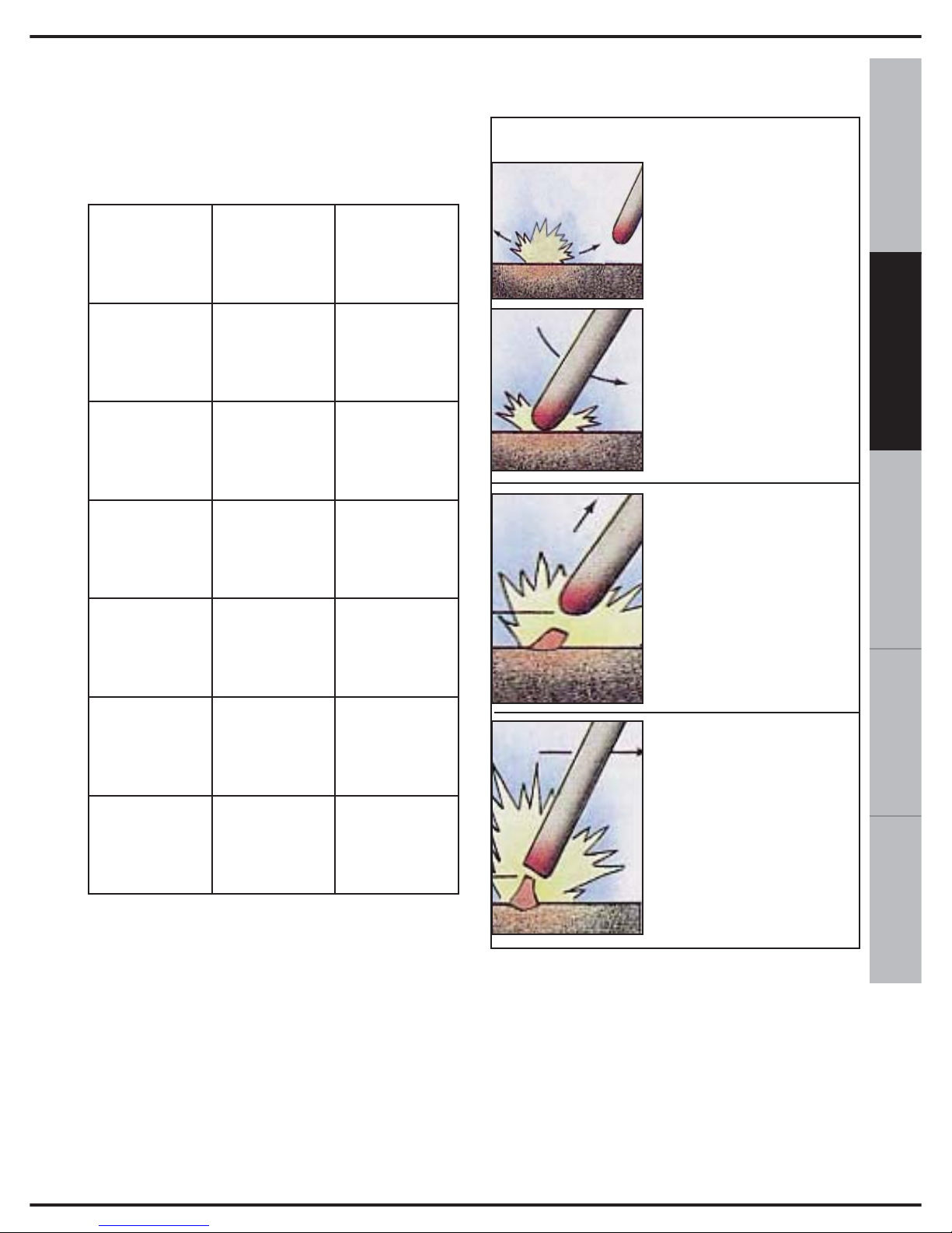
19
ESPAÑOL FRANÇAIS
DEUTSCH
ENGLISH
ITALIANO
10. WELDING TABLE
Use the table below to calculate the
welding current, according to the type of
electrode used:
11. CONNECTION FOR MMA
WELDING
The Dinse connector is inserted by
lining-up the key with the groove and
turning the connector in a clockwise
direction until it stops.
The electrode clamp holder and earth must
be connected to the ‘+’ and ‘-‘ terminals,
according to the specifications of the
electrodes used.
12. IGNITING THE MMA ARC
OFF
This is carried out by stopping a while over
the last crater (i.e. the end of the welding
seam), returning slowly on the previously
deposited seam for approximately two
centimetres and, only at this point, moving
the electrode away from the workpiece to
turn off the arc.
ELECTRODE
DIAMETER
WELDING
CURRENT
ELECTRODE
LENGTH
mm A mm
2.0 45 ÷ 60
300
2.5 60 ÷ 100
300
3.25 90 ÷ 140
450
4.0 140 ÷ 170
450
5.0 190 ÷ 230
450
Create the contact for
igniting the arc at a
distance of
approximately 5 cm from
the initial welding point.
Immediately move the
electrode towards the
workpiece, without touching
it, in order to keep the arc
ignited.
Quickly bring the
electrode, without turning
off the arc, towards the
point where the welding
seam will begin.
Begin welding, advancing
slowly. The distance
between the tip of the
electrode and the
workpiece must be as
identical as possible to the
diameter of the electrode
in use.
IGNITION
Page 56
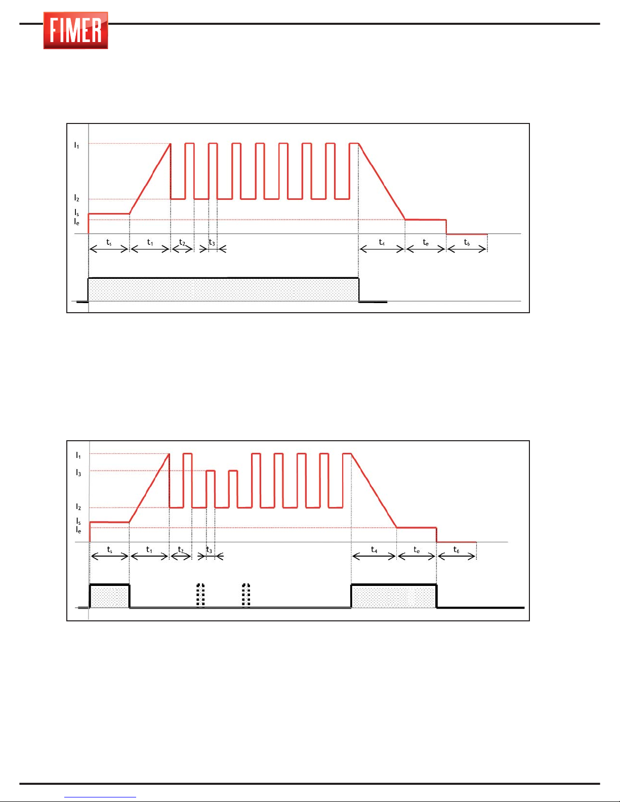
20
In order for a better understanding of the descriptions of the welding parameters
reported, related to the TIG mode, when necessary to make reference to the trends
shown below:
I0, t0: start current, start time
I
1
: welding current
I
2
: background current
I
5
, t5: end current, end time
t
3/t2
x100: pulse balance
1/t
2
: pulse frequency
t
6
: post gas time
I0, t0: start current, start time
I
1
: welding current
I
3
: 2nd level current
I
2
: background current
I
5
, I5: end current, end time
t
3/t2
x100: pulse balance
1/t
2
: pulse frequency
t
6
: post gas time
Torch Button
Torch Button T.B.
13. TIG WELDING
TIG 2t mode with ramps
TIG 4t/4bi mode with ramps
Page 57
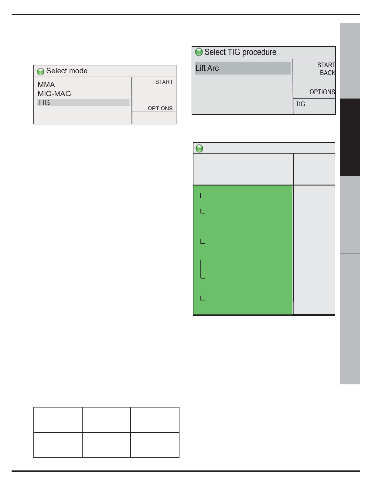
21
ESPAÑOL FRANÇAIS
DEUTSCH
ENGLISH
ITALIANO
To select this welding mode :
turn switch 10, select TIG and press
confirm.
Inert gas welding with an infusible Tungsten
electrode (TIG: Tungsten Inert Gas) for
short, is a welding procedure whereby the
heat is produced by an arc that strikes
between a tungsten electrode (which is not
consumable) and the workpiece. The
welding is carried out by fusing the edges of
the workpiece or by adding other filler
material using specific types of rod to create
a joint. The torch is ignited by touching the
workpiece with the electrode and then lifting.
The TIG procedure can be adapted to any
work position and can also be applied to
very thin sheets of metal (0,2-0,3 mm). The
TIG procedure is distinguished by the ease
with which the arc can be controlled, a
powerful and concentrated thermal source
and the simple manner in which the filler
material can be controlled. This makes the
TIG procedure particularly suitable for
precision welding on a wide variety of
thicknesses, in difficult positions and on
pipes which require full penetration. The TIG
procedure can be used on various types of
metals, such as, ferrous materials, alloys,
nickel, copper, titanium, magnesium.
During welding, potentiometer 9 in fig. 1, for
example, regulates the welding current. The
correct connection of the torch and earth
cable is shown in the following table:
13.1 TIG WELDING (Lift-Arc)
Select this option and the welding screen
will appear:
ADJUSTMENTS AND SETTINGS:
Button 9 controls the current and the
machine power.
Button 10 adjusts the welding settings on
the screen:
2t-4t-4bilevel: Used to set the operating
mode to 2 times or 4 times.
2t: In 2t operating mode pressing the button
causes the protective gas to be released;
when the electrode is raised from the piece
the electric arc is struck, with the initial current and/or ramp-up, which remains on for
the entire time the button is held down.
When the button is released the machine
starts the ramp-down of the current and/or
the final current, if set.
WELDING
PROCESS
Front socket
+
14 of Fig.1
Front socket
-
12 of Fig.1
TIG
EARTH
CABLE
TORCH
CABLE
Ready to weld
START
BACK
MEM +
OPTIONS
150A
15,0V
>
TIG
Lift
2s-4s-4bilevel
2nd level current
start current
start time
slope up
slope down
end current
end time
post gas time
pulse mode
background current
pulse frequency
pulse balance
water pump
remote
min current
spot welding
2t
-50%
50%
0,0s
0,0s
0,0s
20%
0,0s
5,0s
OFF
50%
10,0
50%
OFF
OFF
10A
0,0s
Page 58

22
4t: In the 4t operating mode, when the but-
ton is pressed for the first time the protective
gas is released, then when the electrode is
raised from the piece the electric arc is
struck.
The current delivered corresponds to the initial current parameter as long as the button
is not released, then the machine performs
the ramp-up if set. The next time the button
is pressed the machine performs the rampdown of the current, if set, and the final current (until the button is released), and then
the post gas phase. If the button is released
immediately the machine performs the rampdown of the current (if set) and then the post
gas phase.
4bi: This operation is similar to the 4t mode
with the only difference that pressing the
torch button for short periods (< 1s) during
welding (after the initial ramp) cause the passage of the current from the first level I1 to
the second level I2; holding the button down
(> 1s) causes the start of the end of the weld
(ramp-down and/or final current if set).
2nd level current: If the value 4bi of the 2t4t-4bilevel parameter is selected this makes
it possible to set the 2nd level current as a
percentage of the welding current.
Start current: Used to set the value to which
the welding current is raised immediately
after the electric arc has been struck.
Start time: Used to set the time for which
the current determined by the initial current
parameter is applied.
In 4t/4bi mode (if the spot weld parameter is
equal to 0) this time has no effect and the initial current is maintained as long as the torch
button is held down.
Slope up: Used to set the duration of the
ramp-up of the welding current.
Slope down: Used to set the duration of the
ramp-down of the welding current.
End current: Used to set the value which
the welding current reaches at the end of the
ramp-down.
End time: Used to set the time for which the
current determined by the final current
parameter is applied.
In 4t/4bi mode this time has no effect and the
initial current is maintained as long as the
torch button is held down.
Post gas time: Used to set the time of gas
delivery after the welding current has
stopped.
Pulse mode: Used to activate (Hz) or deactivate (OFF) the pulse welding mode; with
the pulse welding mode active (Hz) the
machine delivers the welding current for a
certain time and the current determined by
the base current parameter for another period of time. The number of current impulses
per unit time is given by the value of the frequency parameter.
The pulsation is activated only during the
welding phase and not during the initial/final
current phases or during the ramps.
Background current: Used to set the base
current used during generation of the pulses.
Pulse frequency: Used to set the number of
current impulses per unit time when the
pulse welding mode is active.
Pulse balance: This represents the percentage of time for which the welding current
is applied when the pulse welding mode is
active.
Water pump: Used to switch on (ON) or
switch off (OFF) the water pump unit if present.
Remote: Used to switch on (ON) or switch
off (OFF) the remote control of the intensity
of the current delivered.
Min current: Used to set the minimum output current when the remote control is at the
minimum adjustment value.
Spot welding: Used to set (if other than 0)
the maximum duration of the weld.
Page 59
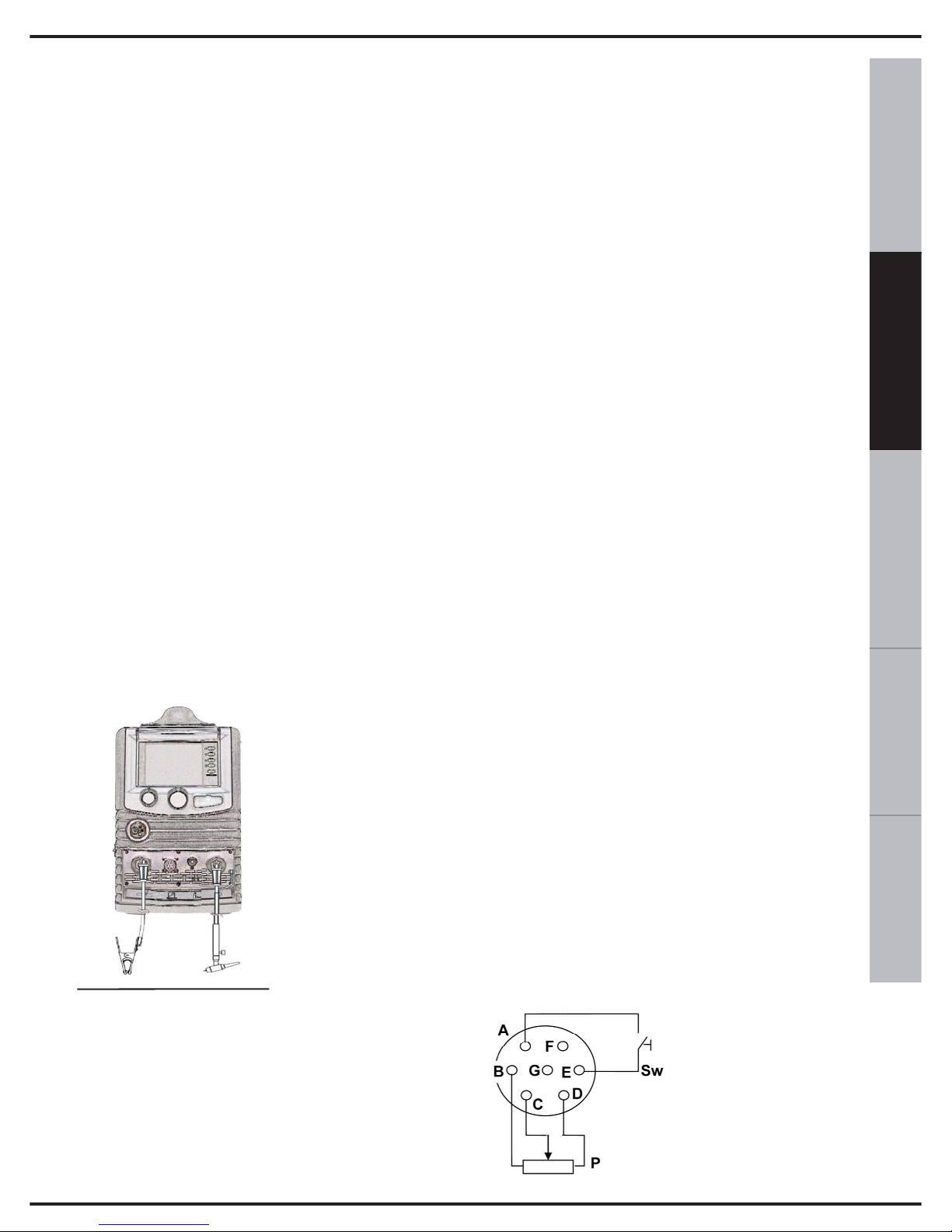
23
ESPAÑOL FRANÇAIS
DEUTSCH
ENGLISH
ITALIANO
14. CONNECTOR FOR TIG WELDING
1) Connect the earth cable to the appropriate
‘+’ socket on the front of the device (14 of fig.1).
Insert by lining-up the key with the groove
and turn in a clockwise direction until it stops.
Do not fasten too tightly!
2) Connect the torch to the appropriate ‘-‘
socket on the front of the device (12 of fig 1).
3) Insert by lining-up the key with the groove
and turn in a clockwise direction until it stops.
Do not fasten too tightly!
4) Insert the torch pulse signal connector into
the socket
TIG WELDING:
Before connecting the gas make sure the
cylinder contains Inert gas. Never use any
other type of gas.
Connect the pressure regulator to the
cylinder, after which, connect the latter to the gas tube
of the torch.
TIG welding is usual-
ly carried out with a
constant current, with
a negative pole (‘-‘
see fig.6).
The cable of the TIG torch is then inserted
into the negative socket (12of fig.1), whilst
the earth cable of the workpiece is connec-
ted to the positive socket. (14 of fig.1).
At this stage it is possible to adjust the welding
current using the potentiometer (9 of fig. 1) on
the front panel.
The diameter of the electrode and the welding current settings must be selected according to the characteristics of the material
to be welded.
15. POWER CONNECTOR
Before connecting the machine check the
tension, number of phases and the power
supply frequency. The admissible power
supply is indicated on the information plate
on the machine.
Check that the earth of the welder has been
connected correctly. Furthermore, make sure
that the plug provided with the equipment is
compatible with the local grid sockets. Make
sure that the power supply provides sufficient
power for the machine to function (tension
ranges).
The machine is provided with a specific
power cable that does not usually require an
extension lead; in the event an extension
lead is required, use one of the same
capacity or higher than the machine in use,
according to the length of the cable. A 2.5
mm² three-pole cable + earth, of the same
size or larger.
16. REMOTE CONNECTION
Figure 7 shows the connections of the
remote connector (13 of fig 1).
Where:
Sw is the torch
trigger
P is the potentiometer
for controlling the
current.
Fig.6
Fig.7
Page 60
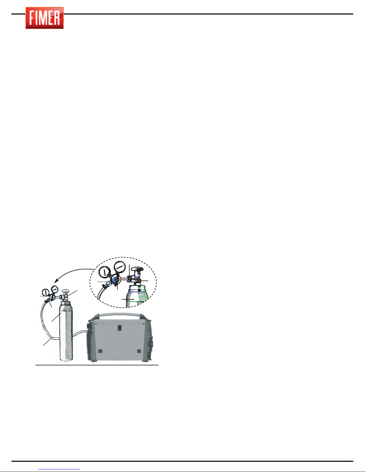
24
16.1 REMOTE CONTROL OF THE
WELDING CURRENT
With remote connector 13 in Fig. 1, it is
possible to adjust the current near to the
point where the welding is being carried out.
To do so, it is necessary to create a
connection with potentiometer P, shown in
figure 7. The value of the potentiometer is not
a critical factor: between 2.2kOhm and
10kOhm 1/2W can be used.
Turn the potentiometer and select the
welding current in a range between minimum
current from display and the set value and
the set value.
17.
CONNECTING THE OUT-PUTS
Connection of the welding cables occurs
via a Dinse quick-connect system with
appropriate connectors.
18.
CONNECTING THE GAS CYLINDER
AND THE GAS REGULATOR
For TIG and MIG welding only. For MMA
welding, skip this paragraph entirely.
1. Connect the pressure regulator (2) to the
cylinder (3). Make sure the regulator is suita-
ble for the cylinder pressure. Attach the con-
nector nut (6) of the regulator (2) to the cylin-
der (3). (Do not screw too tightly; excessive
force could damage the valve (1) of the cylin-
der (3).)
2. Connect the gas tube (4) to the regulator
(2) and secure with a cable tie (5).
3. Make sure that the gas tube is connected
to the welder correctly.
4. Open the valve (1) of the cylinder (3).
Press the torch trigger and check the gas is
flowing correctly.
Warning: Cylinders contain high-pressure
gas; handle with extreme care. Inappropriate
handling and use could cause serious acci-
dents. Never stack the cylinders or expose to
excessive heat, flames or sparks. Do not
bash the cylinders together. Contact your
supplier for further information on the use
and maintenance of the cylinders.
Warning: Never use damaged cylinders: in
this case, advise your supplier immediately.
19. ORDINARY MACHINE
MAINTENANCE
Every three months periodically remove
dust from the suction nozzle using com-
pressed air. Always direct the air from the
inside towards the outside of the machine
to avoid blowing dirt inside the welder.
When carrying out this operation, always
make sure the machine is not connected to
the power supply.
4
3
2
1
6
2
5
1
3
5
Fig.8
Page 61
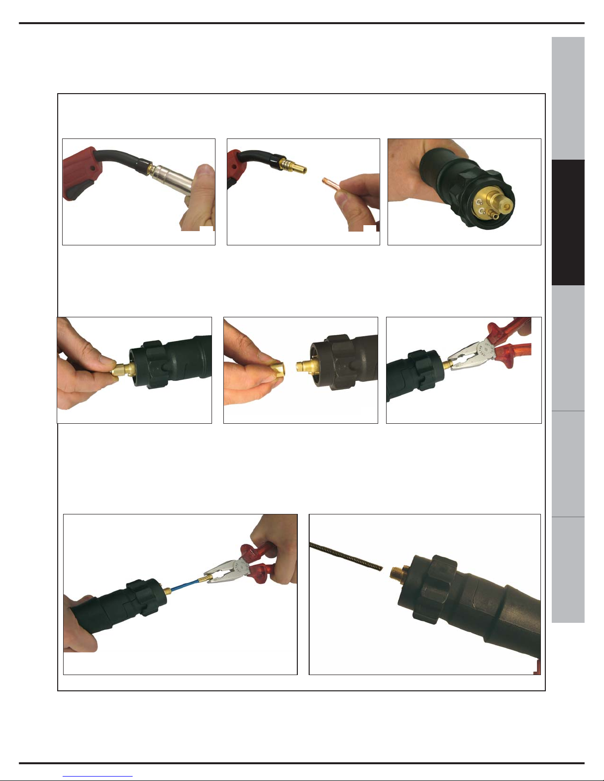
25
ESPAÑOL FRANÇAIS
DEUTSCH
ENGLISH
ITALIANO
When replacing the wire guide sheath follow these instructions carefully:
• Torch side: remove the gas pipe (A).
• Unscrew the wire feed tip (B)
• Connector side (C): turn the terminal nut (D, E) and hold the end of the sheath with a pair
of pliers and pull (F).
• Fully extract the sheath (G).
A
B
C
D
E
F
• Insert the new sheath and push it all the way down to the bottom (H).
• Fasten the wire feeder tip (B) to the torch.
• When replacement has been carried out, reattach the gas nozzle.
G
H
20. REPLACING THE WIREGUIDE SHEATH OF THE TORCH
When carrying out this operation make sure you do not lose the O-RING (rubber
gasket that prevents any eventual gas leaks.
Page 62
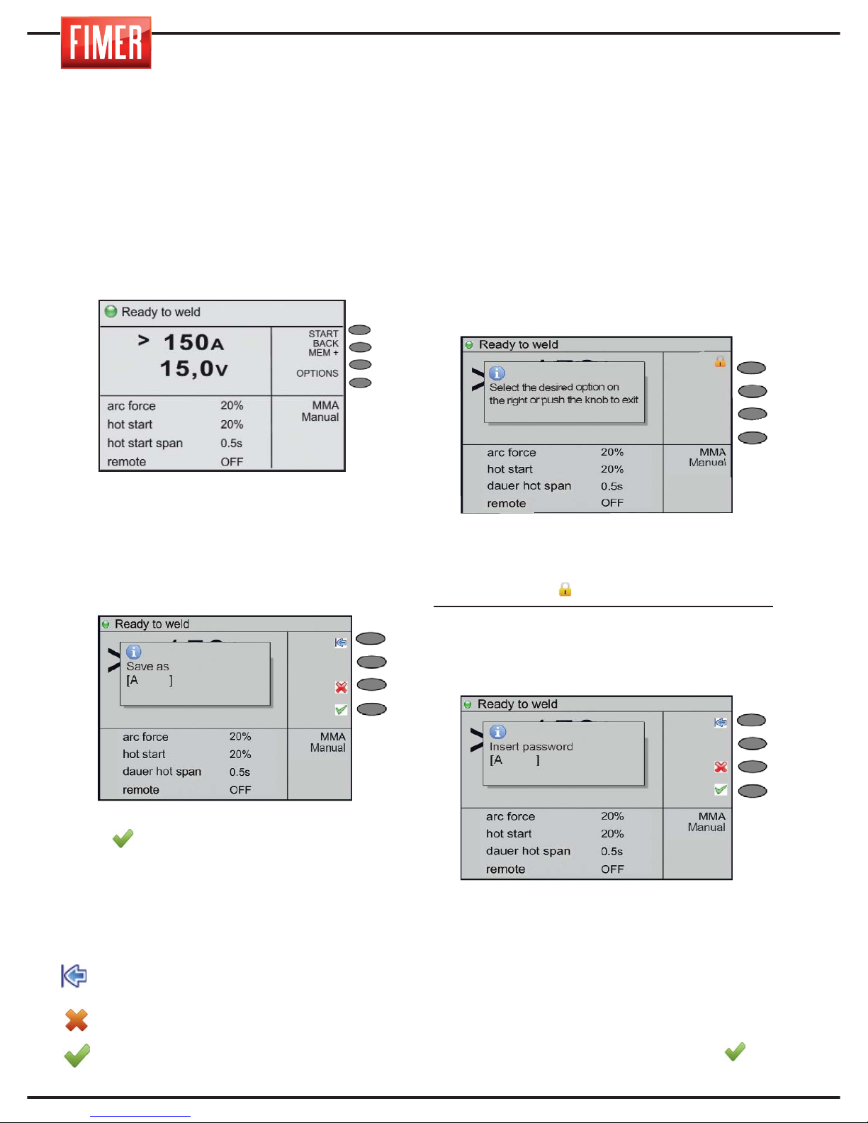
26
21. MEMORISING THE WORK POINT
As illustrated in the previous paragraphs, the
welder allows for a notable personalisation
of the work point (when used both manually
and synergically). The work point for a
workpiece can be saved in the memory and
rapidly recalled at a later date. To save a
work point follow the instructions below:
1. Set the appropriate parameters for the
welding mode required.
2. Press the MEM+ button (4 of fig 1).
3. Turn switch 10 (fig 1), chose the first letter
of the name with which you want to save the
4. Press switch 10 to confirm the selected
letter.
5. Repeat steps 2 and 3 to complete the name.
6. Confirm the name by pressing the button
again . From this moment onwards the
work point will be memorised with its own
name and displayed with the other welding
procedures.
Meaning of the back :
Sp button: cancels the previous letter
inserted.
Cancel: cancels the operation.
OK: confirms the name of the work point.
22. LOCKING A WORK POINT
The welder can lock the functions of
switch 9 and 10, so that once a work point
has been saved it cannot be changed,
unless modified by a member of staff with
a password, which can be defined at the
discretion of the user. To proceed with
locking a work point, it is necessary to first
enter the necessary parameters for the
required welding settings. Once this has
been done, proceed as follows:
1. Press switch 9 of fig. 1 for approximately 5
seconds; the message in Fig. A will appear.
After which, select button 1 of fig. A, with the
name ‘Lock’ on the black and white display
and the symbol for the colour display.
2. You will then be asked to enter the
password, which must be kept safe to make
future modifications of the work point, should
the need arise.
To enter the password, proceed as follows:
1- Turn switch 10 (fig 1) and select the first
letter of the password.
2- To confirm the selection press switch 10.
3- Repeat steps 2 and 3 to complete the
password.
4- Confirm by pressing the switch again.
Fig.A
Fig.B
Page 63
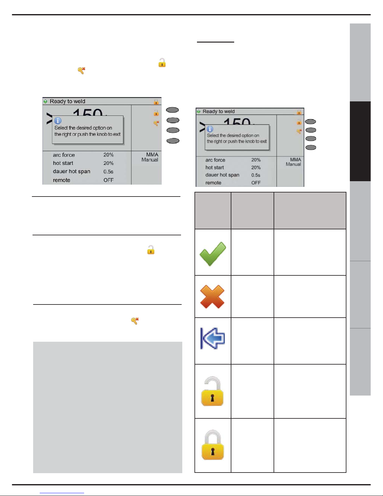
27
ESPAÑOL FRANÇAIS
DEUTSCH
ENGLISH
ITALIANO
3. Once the password has been confirmed
the display will show the message in Fig.
C, a lock symbol in the area 1 of the
display and the functions Unlock and
Reset pw (reset password) which
correspond to buttons 2 and 3 (fig. 1)
respectively, in area 2 of the display;
4. To exit the lock option of the work
stage, briefly press switch 9 in fig. 1;
5. Should the need to modify the work
stage arise, activate the ‘Unlock’ option
by pressing the function button. The
unlock function will require the user to
enter the password that was set and
activated as described above.
6. The reset password option can be
activated by pressing the (Reset pw)
button.
WARNING:
The Reset Password option should
only be used when there is no way of
tracing the work stage and when the
Lock/Unlock password has been lost.
To use this function contact the
constructor technical support
department directly.
Appendix:
titles/button symbols/function buttons
and pop-up notifications
In the following figure and table, you will find
the descriptions of the principal title/button
symbols/function buttons and pop-up
notifications, with regard to error messages
that may appear on the display:
Fig.C
Tasto F1
Tasto F2
Tasto F3
Tasto F4
Symbol
Position
on
display
Description
F4 key
If information needs to be
entered by the user, this
button must be pressed to
confirm the data
F3 key
Press this button in the
event user data is required and you need to cancel the operation;
F1 key
In the event there is a
request for the user to
enter data, use this button to cancel the last digit
entered;
F1 key
When the keyboard lock
function is activated, using
switch 10 (fig.1), this button must be pressed to
deactivate the lock.
F1 key
When the keyboard lock
function is activated,
using switch 10 (fig.1),
this button must be pressed to activate the lock.
Page 64
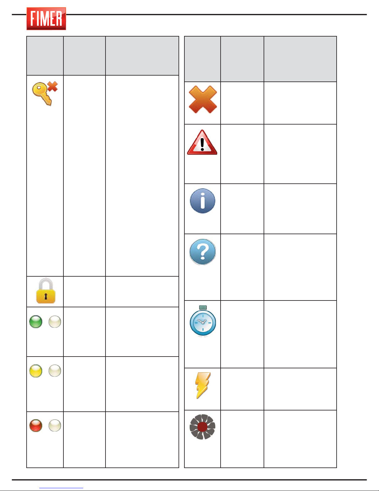
28
Symbol
Position
on
display
Description
F2 key
When the management
function of the keyboard
lock is activated, using switch 9 (fig.1), this indicates
the key to press for cancelling a password that has
been previously memorised by the user (hence
allowing for the insertion of
a new password); if the lock
keyboard function is active, at the same time the
previously memorised password is cancelled, this will
become unlocked.
WARNING: the Reset Password function should
only be used if there is
no trace of the password
or when the password
has been lost. To use this
function contact the constructor technical support department directly.
(2)
This means the keyboard
lock is active.
(1)
Frequently flashes at a frequency of 1Hz, meaning
the application is active;
when the machine is welding, this means that the
duty-cycle of the same is
set between [60, 100]%
(1)
Frequently flashes at a frequency of 1Hz, meaning
that the application is active; when the machine is
welding, this means that
the duty-cycle of the same
is set between [35, 60]%
(1)
Frequently flashes at a
frequency of 1Hz, meaning that the application is
active; when the machine
is welding, this means that
the duty-cycle of the same
is set between [0, 35]%
/
/
/
Symbol
Position
on
display
Description
POP UP
This means the information in the pop-message is an error message, which blocks the
machine functions.
POP UP
This means that the popup message relates to an
operation, carried out by
the user on the machine
that requires attention
(e.g. wire needs feeding
or gas leak)
POP UP
This means that the information in the pop-up
message is informative
(e.g. view firmware versions/SD installed on the
machine)
POP UP
This pop-up message is
advising the user that
they need to enter more
data (e.g.. enter programme name, enter
lock/unlock keyboard
password)
(1)
The replace LED symbol
flashes when a programme is being loaded; once
the programmed has loaded the symbol will disappear and the flashing LED
light will come back on.
(2)
With machines that are
equipped with a HF card,
this means the card will
be continually activated
for a duration of more
than 0.5 sec.
(2)
In machines with a vent
that can be activated by
the programme, this
means that the cooling
vent is switched on.
Page 65
29
ESPAÑOL FRANÇAIS
DEUTSCH
ENGLISH
ITALIANO
E= error W= warning
23. ERROR CODE
Below lists the errors that you may encounter and their description:
Codice
Description
E 8101 Invalid data buffer
E 8102 Error while writing data
E 8103 Invalid CAN index/subindex
E 8104 Read-only CAN object
E 8105 Error while reading data
E 8106 Timeout expired while writing data
E 8107 Timeout expired while reading data
E 8108 MMS application not supported
E 8109 Data connection lost
E 8201 SD card not present
E 8202 SD card unformatted
E 8203 Error while reading data from file
E 8206 Missing data file
E 8209 Synergic table missing!
E 820c SD update required!
E 8fa1 Menu creation aborted
E 8fa2 Hyerarchic menu creation aborted
E 8fa3 Parameters creation aborted
E 8fb1 Wrong configuration
W 4700
Manual wire loading
Warning which appears when the Feed button is pressed
W 4701
Gas purge
Warning which appears when the button is pressed purge gas
E 9001
Antisticking
Warning which appears when the output of the machine is short-circuited, MMA or TIG mode
E 9002
Inverter overtemperature
Warning which appears when the protection is hardware temperature of the inverter
E 9003
Power supply error
Warning which appears when the supply voltage exceeds the specified limits or when there are one or
more phases (three-phase machines only)
E 9004
Thermal overload
Warning which appears when the machine has passed the said duty cycle of Use
E 9005
Water low pressure
Signaling that appears when the pressure of the coolant is low, due to lack of the same liquid, presence
of air bubbles or air bubbles in the cooling circuit
E 9006
AC group overtemperature
Warning which appears when the protection is hardware assembly temperature for polarity reversal
E 9010
Torch trigger pressed, release the torch trigger and / or verify proper operation
Warning which appears when turning on the machine, the trigger is depressed
Page 66

30
INDICATION
CAUSE/S
SOLUTION/ADVICE
Machine switches off
[display: off]
Lack of tension on the supply grid.
Refresh the power supply
tension.
24. TROUBLESHOOTING
Below are a list of some of the most common problems that may arise, with the relative solutions.
Network error
1) Failure of one mains power supply phase
2) Mains overvoltage or undervoltage
1) Check the connection to the
power supply and check that the
fuses are intact
2) Check that the mains has a value
in the range from 360Vrms to
440Vrms.
MALFUNCTIONS DURING WELDING
[display:antisticking]
MMA: electrode in contact with the mass
Remove the electrode from the
workpiece
Failure to strike an arc
1) neither of the cables is
(pincer and earth clamps)
2) the cables are interrupted
3) bad contact between the earth
clamp and piece
4) bad contact between the pincer
and electrode
5) erroneous welding parameter settings
6) the welder does not produce current
1) check the connections
2) check the cables
3) check the connections
4) check the connections
5) check the parameters
6) check the welder
Porous welding seam
Erroneous distance and/or inclination of
the torch
the distance between the electrode and the piece must be approximately equal to the diameter of the
electrode core; for basic electrodes the rule is L=diam. X 0.5, the
inclination must not be excessive
Presence of hydrogen due to humidity in
the coatings of the electrodes, erroneous
conservation of electrodes
replace the electrodes,
keep the electrodes following the
manufacturer’s/supplier’s instructions
Welding arc is too long
keep the correct distance between
the electrode and the piece
No fusion
1) incorrect electrical parameters
2) welding speed to high
3) erroneous preparation of the patches
4) erroneous welding position
1) use the correct parameters,
reduce the speed
2) keep the correct welding
position
3) preparare the joint correctly
(open the angle of the caulker)
4) correct the welding position
Marginal incisions
1) electrical parameters too high
2) erroneous welding position
3) excessive welding speed
1) reduce the electrical parameters
2) correct the welding position
3) reduce the welding speed
Page 67
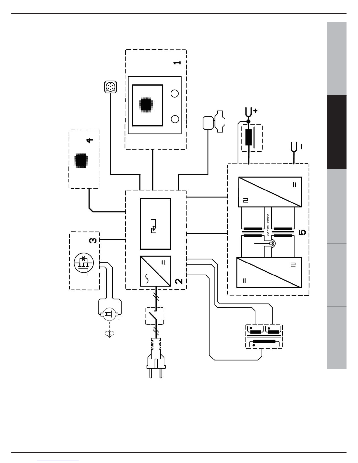
31
ESPAÑOL FRANÇAIS
DEUTSCH
ENGLISH
ITALIANO
1. Control panel
2. Power control board
3. Motor control board
4. Welding process control panel
5. Power Inverter
6. Auxiliary transformer
25. BLOCK DIAGRAM
Page 68
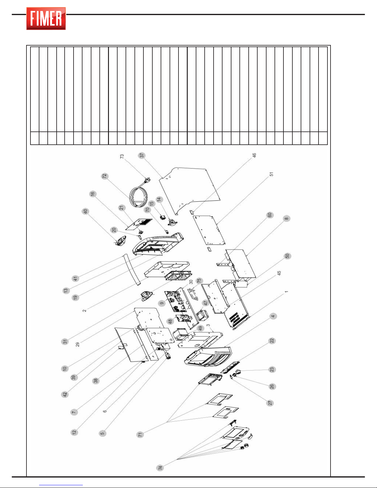
26. SPARE PARTS
4
Plastic front panel
5
Euroconnector Kit
7
Wire feeder
8
Power board
9
Control board
10
Reel support
12
Hinge
13
Upper part of plastic back panel
14
20A cam switch
15
Solenoid valve
16
Rear panel
19
Lower part of shell
20
Fuse block
21
5-pole connector
22
Power panel
23
Dinse
26
7-pole connector
27
Gas connector
31
Fan
37
Hood
38
Fixed left wall
39
Mobile wall
40
Handle holder
41
Handle
42
Sliding closure
47
Inductance
48
Motor control board
49
Auxiliary transformer
50
Power conveyor
60
Lexan fastening clamp for dissipaters
70
Quick connector
71
Kit display
72
Line cable
74
Frontal kit frame
Page 69

1
ESPAÑOL FRANÇAIS
DEUTSCH
ENGLISH
ITALIANO
HAND- UND WARTUNGSBUCH
HAND- UND WARTUNGSBUCH
Fimer dankt Ihnen für den Erwerb dieses Gerätes. Es wird Sie für viele Jahre ohne
Probleme bei Ihrer Arbeit begleiten, wenn Sie die folgenden Angaben und Hinweise
im diesem Hand- und Wartungsbuch richtig befolgen.
Das Handbuch ist Teil des Geräts und hat dieses bei Verkauf oder Weitergabe zu begleiten.
Es obliegt dem Verwender, das Handbuch vollständig und in gutem Zustand aufzubewahren. Der Hersteller behält sich das Recht vor, zu jedem Zeitpunkt ohne Ankündigung Änderungen am Handbuch vorzunehmen.
Jedes Produkt Fimer wurde in Italien in unserer Produktionsstätte entwickelt, geplant
und produziert.
Das garantiert beste Qualität und Zuverlässigkeit.
Die Rechte an Übersetzung, Vervielfältigung oder Anpassung, sei es teilweise oder vollständig, zu egal welchem
Preis (inbegriffen Kopien, Filme und Mikrofilm) sind geschützt und ohne schriftliche Erlaubnis des Herstellers
untersagt.
INHALTSANGABE
INHALTSANGABE
• WARNHINWEISE ........................................................................................... pag. 2, 3, 4
1. ALLGEMEINE EIGENSCHAFTEN UND ANGABEN ZUR
EINSICHT DES HANDBUCHS .................................................................. pag. 5
2. BESCHREIBUNG DES GERÄTS............................................................... pag. 5
3. EINSETZEN DES SCHWEISSDRAHTS................................................. pag. 8
4. MIG/ MAG SCHWEISSEN.......................................................................... pag. 9
4. 1 MIG SCHWEISSEN manueller Short Arc (Kurzbogen)................................... pag. 10
4. 2 MIG SCHWEISSEN synergischer Short Arc (Kurzbogen).......................... pag. 11
4. 3 MIG SCHWEISSEN synergisch mit pulsierendem Bogen.............................. pag. 14
5. VERBINDUNGEN FÜR MIG-SCHWEISSEN.................................................. pag. 16
5.1 MIG-BRENNER........................................................................................ pag. 16
5. 2 ANSCHLUSS FÜR MIG SCHWEISSEN traditionellem Brenner.................. pag. 16
5. 3 ANSCHLUSS FÜR MIG SCHWEISSEN mit Gas und Brenner Push-pull....... pag. 16
6. ERZEUGEN DES LICHTBOGENS BEIM MIG-SCHWEISSEN...................... pag. 17
7. EINSTELLUNG DES SCHWEISSGERÄTS................................................... pag. 17
8. FÜR BESTE SCHWEISSERGEBNISSE................................................................ pag. 17
9. MMA SCHWEISSEN................................................................................... pag. 18
9. 1 MANUELLES MMA SCHWEISSEN............................................................ pag. 18
10 SCHWEISSTABELLE................................................................................ pag. 19
11 ANSCHLUSS FÜR MMA SCHWEISSEN........................................................... pag. 19
12. ERZEUGEN DES LICHTBOGENS BEI MMA............................................. pag. 19
13. WIG SCHWEISSEN.................................................................................. pag. 20
13. 1 WIG SCHWEISSEN (Lift-Arc).................................................................... pag. 21
14. ANSCHLUSS FÜR WIG SCHWEISSEN....................................................... pag. 23
15. NETZANSCHLÜSSE................................................................................. pag. 23
16. FERNVERBINDUNG................................................................................. pag. 23
16.1 FERNBEDIENUNG DER STROMSTÄRKE................................................. pag. 24
17. AUSGANGSANSCHLÜSSE ...................................................................... pag. 24
18. ANSCHLUSS DER GASFLASCHE UND DES GASREGLERS.......................... pag. 24
19. NORMALE WARTUNG DES GERÄTS...................................................... pag. 24
20. ERSATZ DER VERKLEIDUNG ZUR DRAHTFÜHRUNG IM BRENNER........ pag. 25
21. SPEICHERN DES SCHWEISSPUNKTS..................................................... pag. 26
22. SPERREN DES SCHWEISSPUNKTES....................................................... pag. 26
23. ERROR CODE.......................................................................................... pag. 29
24. FEHLERSUCHE....................................................................................... pag. 30
25. BLOCKSCHALDBILD.............................................................................. pag. 31
26. ERSATZTEILE.......................................................................................... pag. 32
Page 70
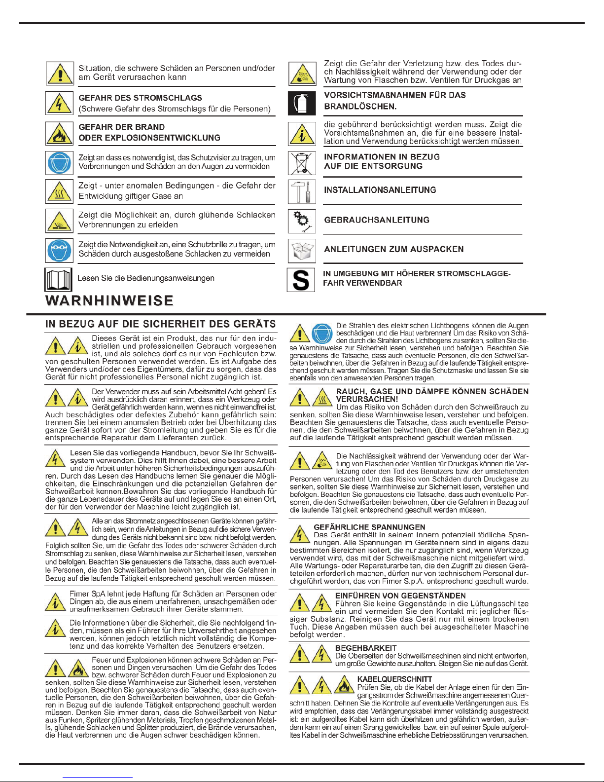
2
VERWENDETE SYMBOLE
Page 71
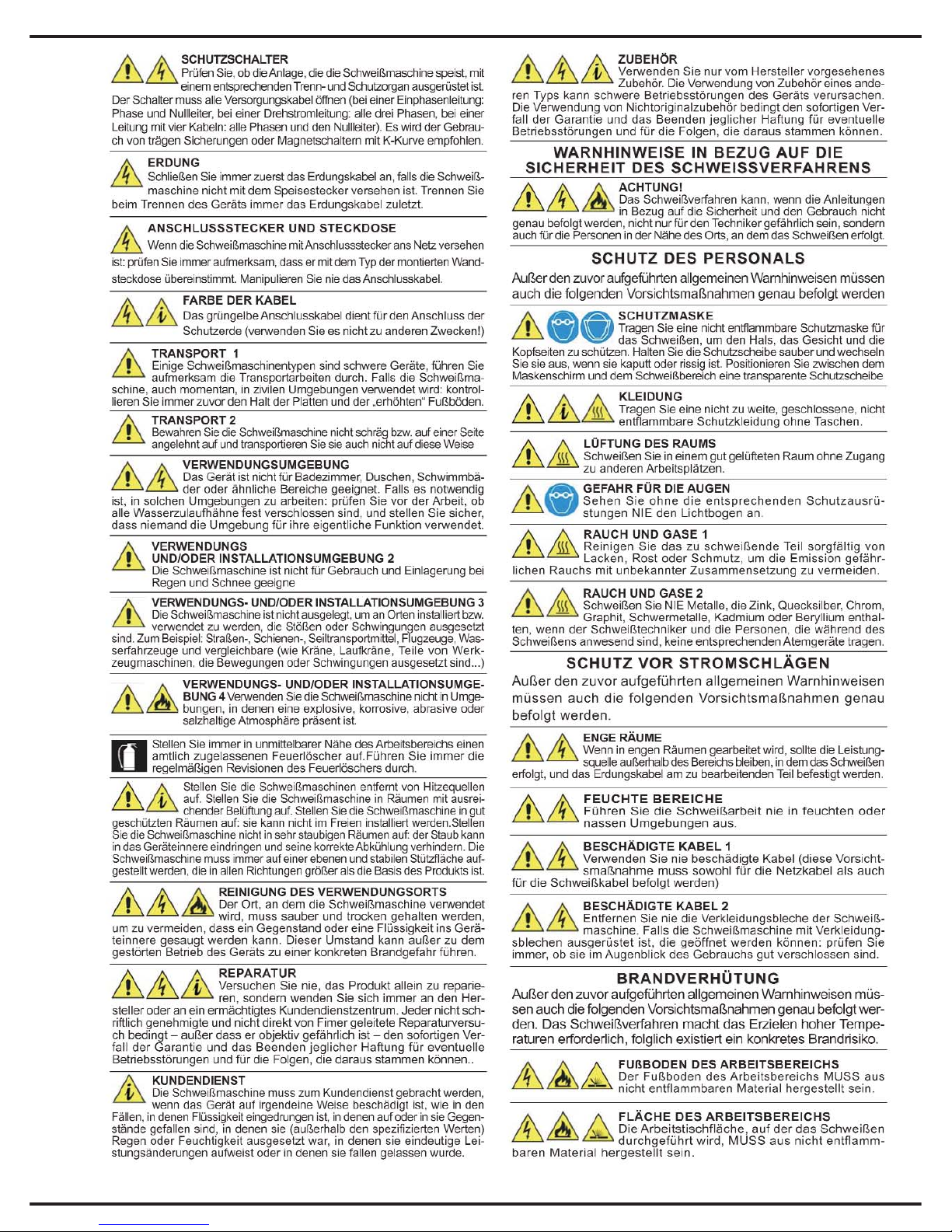
3
Page 72
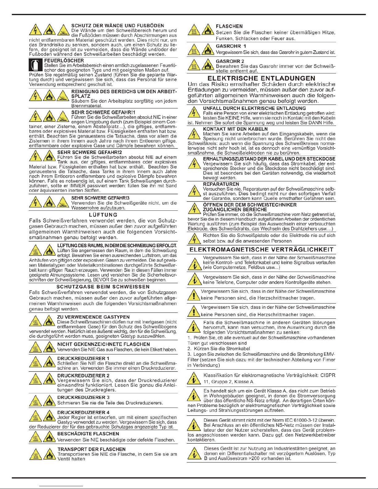
4
Page 73
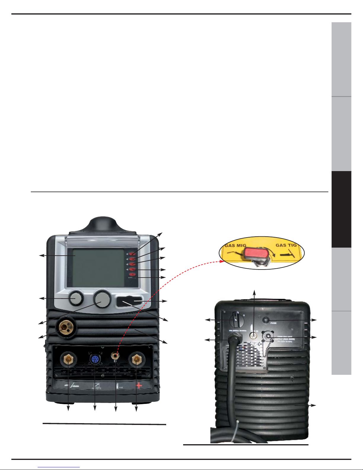
5
ESPAÑOL FRANÇAIS
DEUTSCH
ENGLISH
ITALIANO
1. ALLGEMEINE EIGENSCHAFTEN UND
ANGABEN ZUR EINSICHT DES
HANDBUCHS
Die Schweißgeräte des Typs „TM 236
EVO”
sind Geräte, die mit der Technologie
INVERTER hergestellt wurden. Es handelt
sich um Geräte, die extrem kompakt und
vielseitig sind, und in den Situationen
perfekt einsetzbar sind, in denen ein
Minimum an Platzaufwand und maximale
Leistung benötigt werden.
Diese Schweißgeräte erlauben das Schweißen
mit den Verfahren MMA, WIG und MIG/ MAG
manuell und synergisch (Short Arc, pulsend
und doppelpulsend).
Das innovative System eines Interface mit
dem Bediener über einen breiten TFT 5,7
Zoll Farbbildschirm gestattet einen einfachen
und intuitiven Gebrauch des Geräts. Dabei
können alle Schweißparameter persönlich
eingestellt werden.
Alle Hauptparameter des Geräts sind auf
einer entsprechenden Memorykarte
abgespeichert (SD-Card). Auf diese Art und
Weise ist es möglich, Ihr Gerät mit den
neuesten Entwicklungen im Bereich des
Schweißens zu aktualisieren.
Die Herausnahme der Memorykarte
behindert die Funktion des Geräts, was eine
erhöhte Sicherheit gegen Diebstahl oder
nicht autorisierte Verwendung darstellt.
Dank der fortgeschrittenen Kontrolltechniken
verfügt das Produkt über eine hohe
Zuverlässigkeit und Einfachheit im Gebrauch.
Dieses Handbuch führt im Detail die
Vorgaben und Funktionsweisen des Geräts
auf: Eine komplette Konsultation erlaubt es
Ihnen, die extreme Flexibilität und
Handlichkeit im Gebrauch zu schätzen.
Achtung: Das Gerät darf nur für die im
Handbuch beschriebenen Verfahren eingesetzt
werden und darf nicht für unsachgemäße
Anwendungen eingesetzt werden.
2. BESCHREIBUNG DES GERÄTS
Abb. 1
11
20
Abb. 2
17
19
18
1
2
3
4
5
6
10
9
16
12
14
15
13
11
7
8
I
N
T
E
R
N
E
S
V
E
N
T
I
L
21
Mit dieser Auswahl können
Sie wählen, das Ausströmen
des Gases für jeden
Schweißprozess gewidmet
Page 74
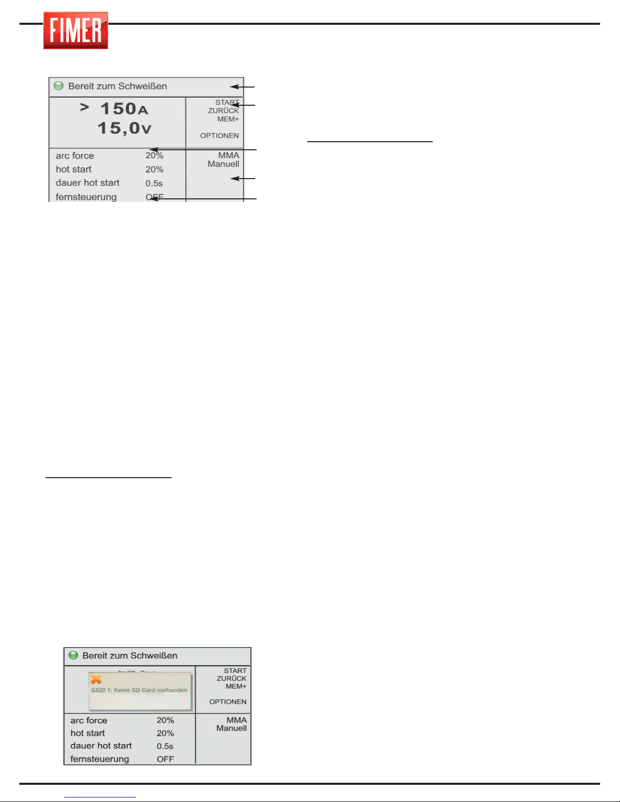
6
ABBILDUNG 1:
1. Graphisches Display:
Auf dem Display 5,7 Zoll Farb'' werden ja nach
Schweißmodus oder Einstellungsmodus
verschiedene Bildschirmseiten angezeigt.
Bei gewähltem Schweißmodus ist die
Bildschirmseite in 5 Hauptbereiche untergliedert:
Bereich 1: Maschinenstatus
Bereich 2: Bedeutung der aktiven Tasten
(Tasten 2, 3, 4, 5, 6 in Abb.1)
Bereich 3: Eingestellter Größenwert
Bereich 4: Art des verfahren ausgewählt
Bereich 5: Zeigt die für die verschiedenen
Schweißparameter eingestellten Werte an
(zur Veränderung des eingestellten Werts
Parameter mit Drehknopf 10 anwählen und
Drehknopf zur Bestätigung drücken; Der
angewählte Wert wird gekennzeichnet. Durch
Drehen des Drehknopfs wird der Wert
verändert, zur Bestätigung des neuen Werts
muss der Drehknopf 10 erneut gedrückt
werden).
Gekennzeichneter Wert: Zeigt den Parameter
an, der mit Drehknopf 10 verstellt wird.
ANSICHTEN:
- Beim Einschalten werden das Fimer Firmenlogo
und die Revision der Firmware angezeigt.
BEDIENSCHALTER:
(2, 3, 4, 5,6 der Abb. 1)
Jedem Schalter wird eine spezielle Funktion
zugewiesen, die auf dem Display angezeigt wird.
7.SD-Fach: In diesem Fach mit
Kunststoffabdeckung muss die im
Lieferumfang enthaltene SD-Card eingelegt
sein; Ohne diese SB-Card ist die Maschine
nicht funktionsfähig und auf dem Display wird
eine entsprechende Meldung angezeigt.
8. USB-Port: Nur für Service-Zwecke.
9. Drehknopf für die Einstellung der
wichtigsten Schweißparameter: Mit diesem
Drehknopf wird der wichtigste
Schweißparameter eingestellt:
MMA/WIG Schweißen:
zur Einstellung des
Schweißstroms.
11. Belüftungsgitter
(stets freizuhalten).
12. “-” Buchse an der Vorderseite:
Stecker mit -Pol.
Anschlussbuchse WIG-Modus.
MMA-Modus: Massezange
MIG-Modus: Massezange
13. Stecker für die Überwachung der
Stromstärke.
14. “+” Buchse an der Vorderseite:presa
polo positivo.
MMA-Modus: Elektrodenhalterzange
WIG-Modus: Massezange
MIG-Modus mit Gas: Nicht verwendet
15. GAS-Ausgang:
MMA-Modus: nicht aktiv
WIG-Modus: Gasanschluss für den
Schweißbrenner (internes Ventil auf WIG GAS)
MIG-Modus mit Gas: nicht aktiv (internes
Ventil auf MIG GAS)
16. SCHNELLVERBINDUNG
SCHWEISSBRENNER
Ausgangsverbindung (positiv) für den
Stecker (Euro) des Schweißbrenners, für
elektrischen Kontakt und Gas.
ABBILDUNG 2:
17. EIN-AUS-Schalter: Zum Ein- und
Ausschalten der Maschine
18. Eingangskabel: Netzverbindungskabel
mit Netzstecker.
19. Schweißgas-Eingang
MMA-Modus: Nicht verwendet
WIG-Modus: Anschluss an die Gasflasche
MIG-Modus mit Gas: Anschluss an die
Gasflasche
20. Sicherungen
21.Versorgungskabel der
Flüssigkeitskühlungsanlage (Option):
Achtung, gefährliche Spannung im
Steckverbinder: NIEMALS zweckfremd
gebrauchen.
Teil 1
Teil 2
Teil 3
Teil 4
Teil 5
Page 75
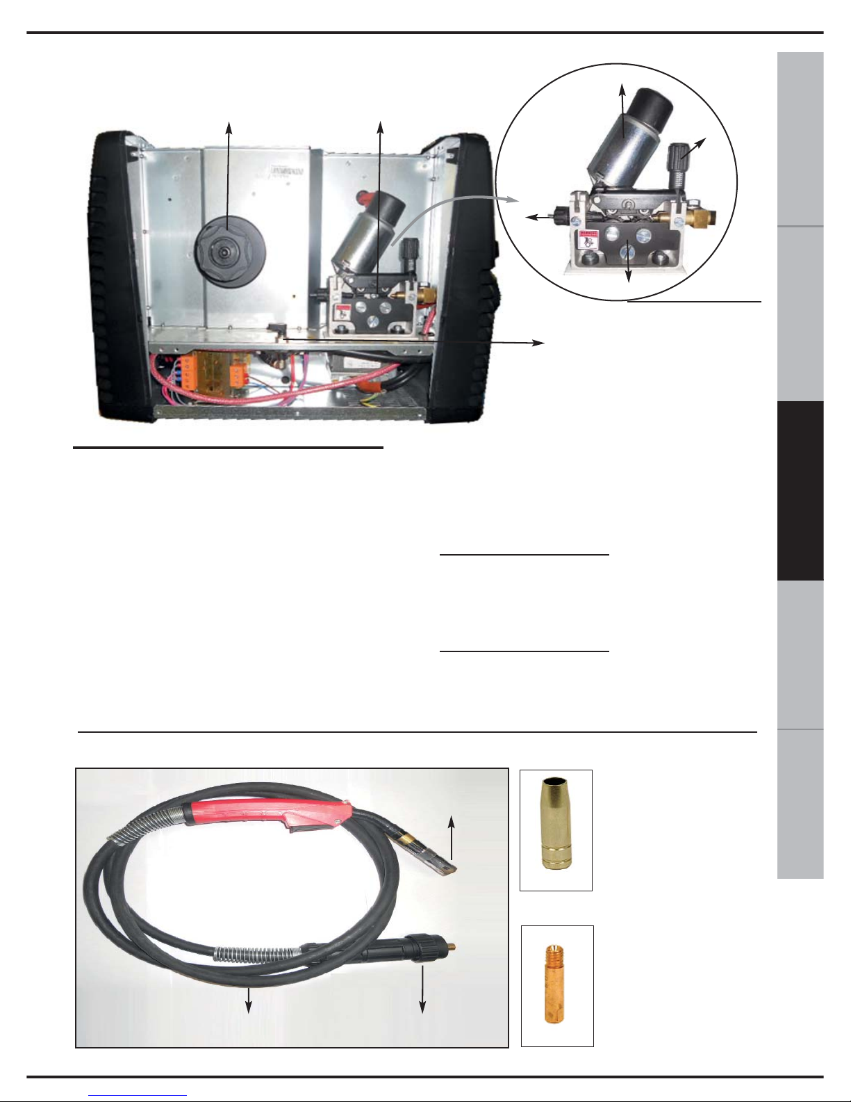
ITALIANO
ENGLISH
DEUTSCH
FRANÇAISESPAÑOL
7
22
23
24
26
25
27
28
ABBILDUNG 3:
22. HALTERUNG FÜR DRAHTSPULE
die Spule aus Draht 300mm benötigt eine
externe Unterstützung (cod. 580.727.001)
23. DRAHTVORSCHUB: Mit größerem
Detail in Abb. 3A aufzeigen.
24. DRAHTKURBELMOTORS
25. REGLER DRAHTSPANNUNG: Gestattet
die Regulierung der Spannung des
Schweißdrahts.
26. DRAHTEINGANG DES
DRAHTKURBELMOTORS
27. DRAHTKURBELROLLEN
28. GASVENTIL: DREI MÖGLICHE
POSITIONEN DES GASVENTILS
MIG GAS Position:
Leitet über den
Gasflaschenanschluss 19 Schweißgas zum
Eurostecker (Korrekte Ventilstellung für MIGSchweißen mit Schutzgas).
WIG GAS Position:
Leitet über den
Gasflaschenanschluss 19 Schweißgas zum
Anschluss 14 an der Gerätevorderseite
(Korrekte Ventilstellung für WIG-Schweißen)
Abb. 3
Abb. 3A
SCHWEISSBRENNER
Abb.4A
Abb.4B
DÜSE
GASAUSTRITT
DRAHTFÜHRUN
GSSPITZE
KABEL
EUROSTECKER
Abb.4
BRENNERGEHÄUSE
Page 76
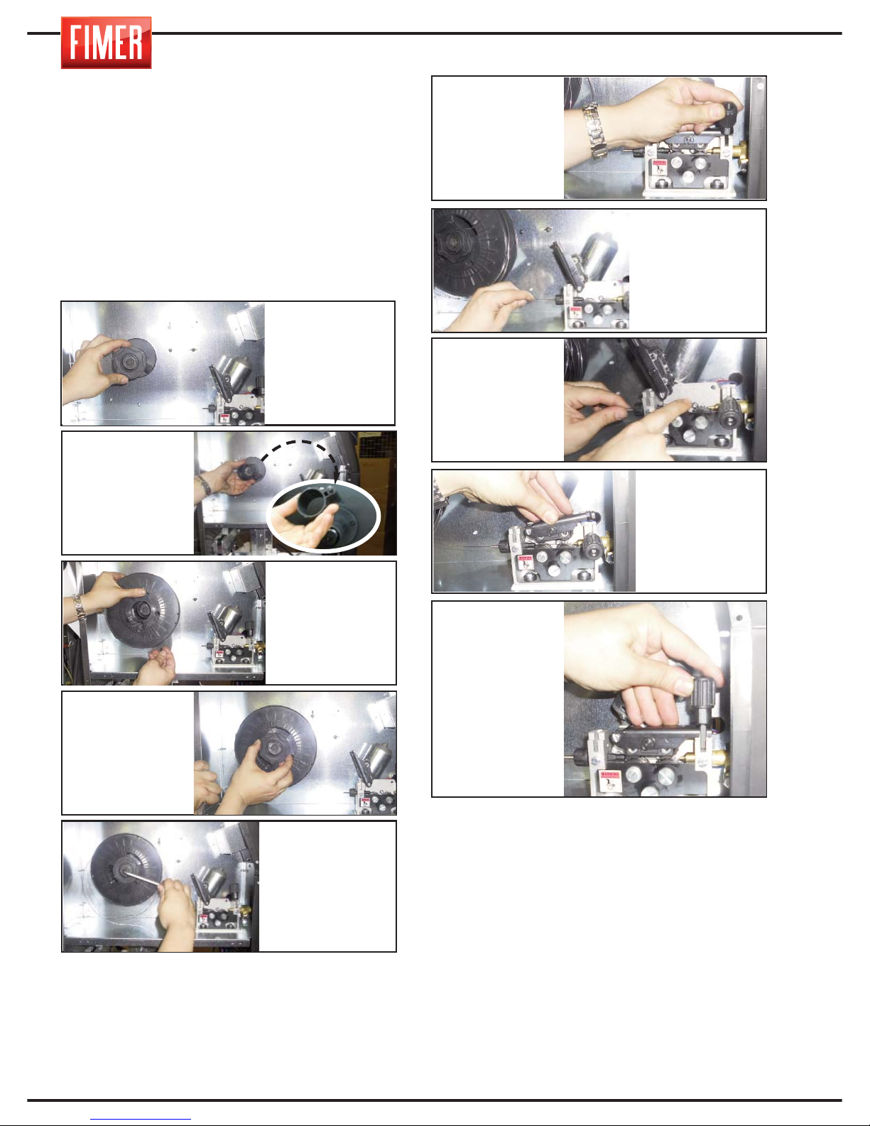
8
3. EINSETZEN DES
SCHWEISSDRAHTS
Zum Einsetzen des Schweißdrahts folgen Sie den
nachfolgenden Anweisungen und halten sich an die
angegebene Reihenfolge.
Achtung: Bevor Sie mit der Installation fortfahren, entfernen Sie stets die Gasdüse (Abb. 4A) und die
Drahtführungsspitze (Abb. 4B) vom Brennerkopf (Abb. 4).
1. Entfernen Sie das Netzkabel von der
Stromquelle (18 der Abb. 2)
Anmerkung Bei einer Änderung des Drahtdurchmessers
sollten Sie sich vergewissern, dass die korrekte
Einkerbung der Drahtkurbel in Richtung der Innenseite des
Geräts gerichtet ist. Dafür vergewissern Sie sich, dass der
Wert, der dem Durchmesser und dem verwendeten Draht
entspricht, lesbar (also in Richtung Außenseite des Geräts
gerichtet) ist. Beachten Sie, dass die Kurbeln mit einer
Einkerbung „V" sich für das Kurbeln von Eisen- oder
Edelstahldraht eignen. Die Kurbeln mit „U" Kerben hingegen eignen sich für Aluminiumdrähte.
Achtung: Bevor Sie zum nächsten Schritt übergehen, vergewissern Sie sich, dass der Brennerdraht (Abb. 4)
gespannt ist und der Schweißdraht keine scharfen Ecken
oder Kanten aufweist. Folgen Sie dieser Anweisung nicht,
so kann die Verkleidung der Drahtführung im Brenner
beschädigt werden. Sobald der Draht durch den Brenner
geführt wurde, sind die Drahtführungsspitze und die
Gasdüse festzuschrauben.
Ziehen Sie den Inbusschlüssel so fest, dass eine
gute Bremswirkung erzielt wird: Zu fest gezogen
wird die Bremswirkung jedoch zu stark und droht
die Abspulbewegung des Drahtes zu blockieren.
Eine zu leichte Bremswirkung hingegen kann dazu
führen, dass der Draht nach Beendigung des
Schweißens versehentlich weiter abgespult wird.
2. Schrauben
Sie den gerändelten Knopf in
der Mitte der
Spulenhalterun
g auf (22 der
Abb. 3).
7. Führen Sie den
Draht in die
Eingangsröhre (26
der Abb. 3A) des
Drahtkurbelmotos
ein.
9. Senken Sie
die oberen
Kurbeln ab.
4. Entfernen Sie
die Plastikhülle
der neuen Spule
und setzen Sie
diese auf die
Halterung auf (22
der Abb. 3).
6. Achten Sie
darauf, dass der
Inbusschlüssel (M8)
in der Mitte der
Spulenhalterung als
Bremssystem für
den Draht dient.
3. Entfernen Sie
gegebenenfalls
den
Abstandhalter je
nach Größe der
verwendeten
Spule.
5.
Schrauben
Sie den gerän-
delten Knopf wie-
der fest.
6. Senken Sie die
Rollenzuführung
(25 di Fig. 3A)
8. Lassen Sie ihn
bis unter die
Drahtkurbeln bis
zum Eingang des
Eurosteckers
vorrollen.
10. Heben den
Knopf aus
Kunststoff (25
von Fig. 3A) des
Druckreglers des
Drahtes.
Page 77
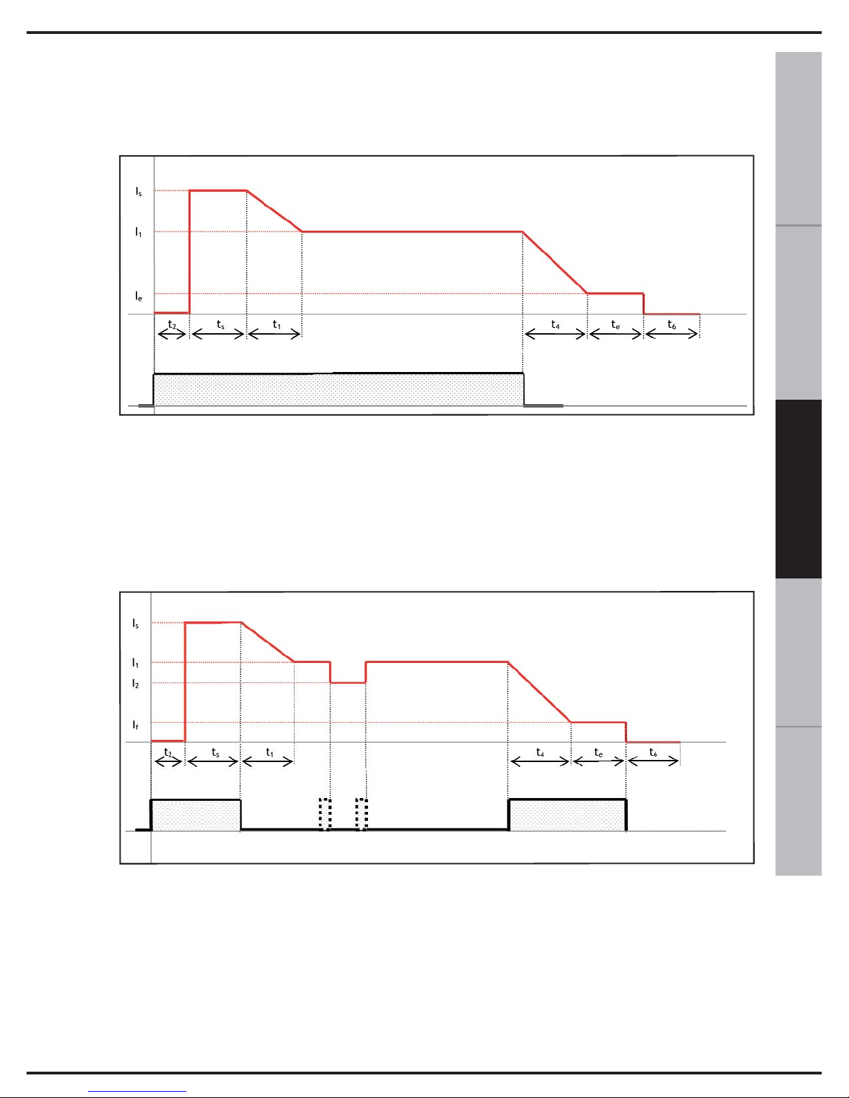
9
ESPAÑOL FRANÇAIS
DEUTSCH
ENGLISH
ITALIANO
Um zu einem besseren Verständnis der Beschreibung der Schweißparameter berichtet, bezogen auf das MIG/MAG, wenn notwendig, auf die Trends unten machen:
t
2
: Gasvorströmzeit
I
s
, t
s
: Startstrom , Startstromzeit
t
1
: Slope I
s
->I
1
I
1
: Schweißstrom
I
2
: Zweite Stromstufe
t
4
: Slope I
1
->I
e
I
e
, t
e
:
Ende Strom, Endzeit
t
6
:
Nachgaszeit
t
2
: Gasvorströmzeit
I
s
, t
s
: Startstrom, Startstromzeit
t
1
: Slope I
s
->I
1
I
1
: Schweißstrom
I
2
: Zweite Stromstufe
t
4
: Slope I
1
->I
e
I
e
, t
e
:
Ende Strom, Endzeit
t
6
:
Nachgaszeit
Torch KnopfT.K.
4. MIG/ MAG SCHWEISSEN
Torch Knopf
MIG 2t Modus mit Rampen
MIG 4t/4bi Modus mit Rampen
Page 78
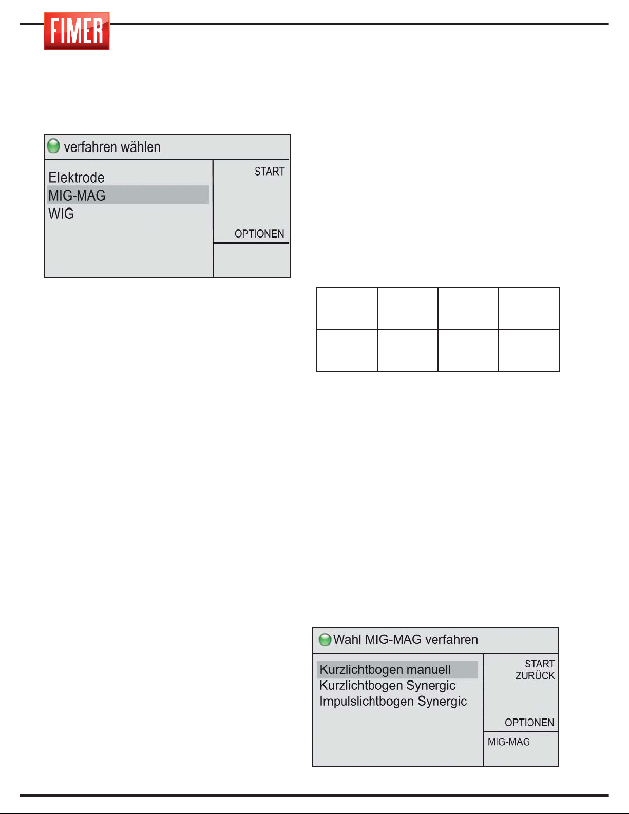
Zur Auswahl dieser Schweißtechnik:
Über den Drehknopf 10 wählen Sie WIG
und drücken zur Bestätigung.
Das MIG/MAG Schweißen (Metal Inert Gas e
Metal Active Gas) ist ein Schweißvorgang mit
kontinuierlichem Draht, der höhere
Stromdichten im Vergleich zum Schweißen
mit beschichteten Elektroden gestattet.
Somit werden größere Penetrationen
erreicht und die Schweißnaht muss beim
Füllen weniger bearbeitet werden.
Der Schweißvorgang erfolgt, indem eine
Metallelektrode aus Draht, die mit
gleichmäßiger Geschwindigkeit ausgegeben
wird und vom Schweißbrennerkopf kontrolliert
wird, in einem Schweißbad aufgelöst wird.
Sobald der Draht zu laufen beginnt und das
zu schweißende Arbeitsstück berührt, wird
ein elektrischer Bogen erzeugt. Dieser
Bogen löst den Draht auf, der sich auf
dem Arbeitsstück niederlässt.
Dieser Schweißvorgang kann die folgenden
Drahtarten verwenden:
1. Volldraht: Muss stets mit Schutzgas
verwendet werden.
2. Gefüllter Draht für Schweißen mit Gas:
besitzt in seinem Inneren ein Mineralprodukt,
welches die Schweißeigenschaften verbessert
(muss stets mit Gas verwendet werden).
Die Verbindungsstromstärke des Brennerkopfs
und des Massenkabels wird in der
nachfolgenden Tabelle angegeben.
Über den Knopf 9 kann die Potenz des
Geräts ausgewählt werden.
Es gibt drei Hauptarten zum Schweißen MIG-MAG:
1. Kurzlichtbogen manuell
2. Kurzlichtbogen Synergic
3. Impulslichtbogen Synergic
4.1 MIG SCHWEISSEN manueller Short Arc
(Kurzbogen)
Durch Drehen des Drehknopfes 10 kann unter
den verschiedenen Schweißmöglichkeiten
MIG/MAG ausgewählt werden. Durch Drücken
des Knopfes wird die Auswahl bestätigt.
SCHWEIS-
SPROZESS
Eurostecker
16 Abb.1
Frontstecker
+
14 Abb .1
Frontstecker
-
12 Abb .1
MIG/MAG
BRENNERKA-
BEL
NICHT
VERWENDET
MASSENKABEL
10
Page 79
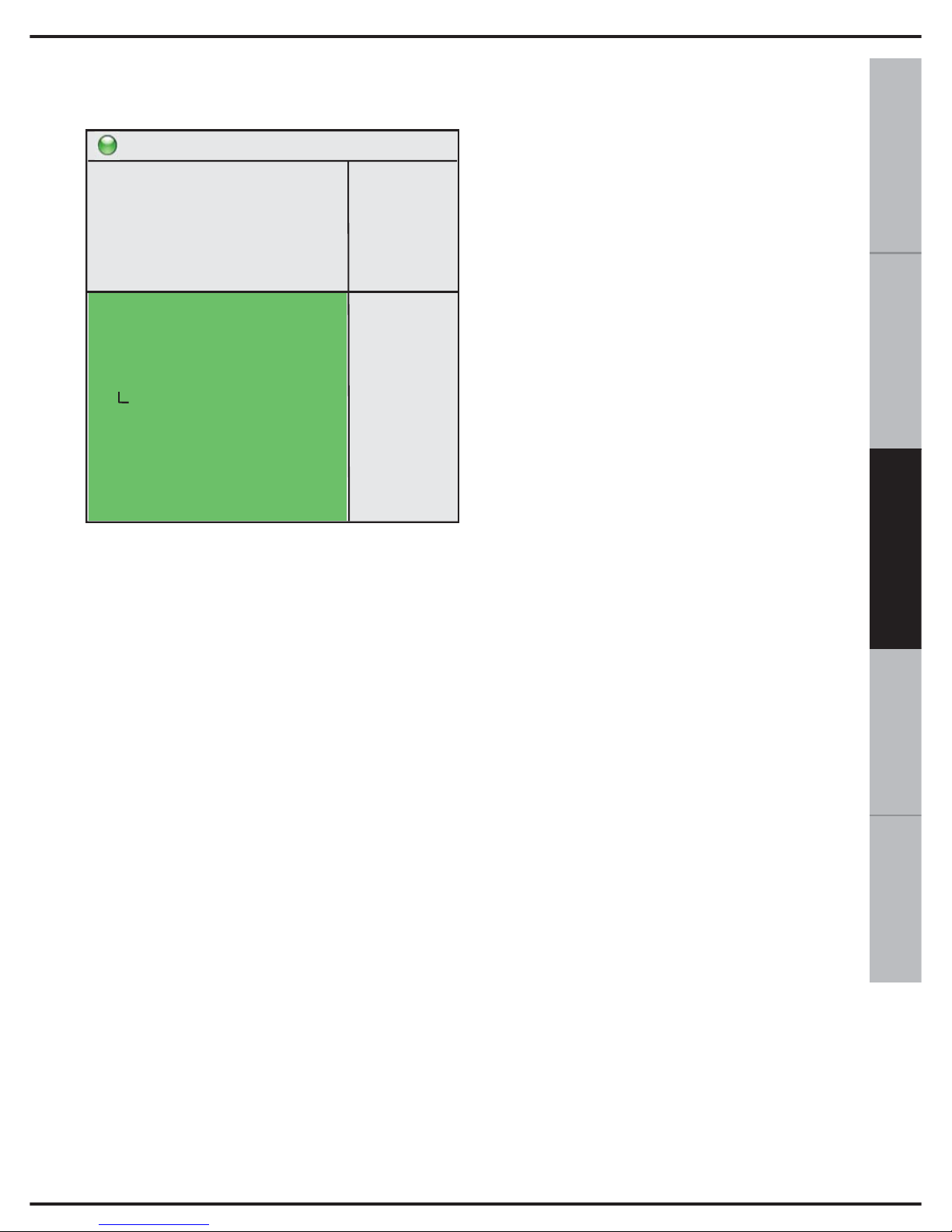
11
ESPAÑOL FRANÇAIS
DEUTSCH
ENGLISH
ITALIANO
Nach Auswahl gelangt man zum Display
„Schweißen"
Drahtgeschwindigkeit: Ermöglicht die
Einstellung der Vorschubgeschwindigkeit
des zum Schweißen verwendeten Drahts.
SoftStart/Einschleichen: Ermöglicht die
Änderung der Vorschubgeschwindigkeit des
Drahts, so dass eine sanfte
Schweißzündung erfolgt, je höher der Wert,
desto niedriger die
Vorschubgeschwindigkeit.
Drossel: Ermöglicht die Änderung der
Variationsgeschwindigkeit des
Schweißstroms, um eine härteren
(niedrigere Werte) und einen weicheren
(höhere Werte) Lichtbogen zu erhalten.
2/4 Takt/S-4 Takt: Ermöglicht die
Einschaltung der Zweitakt- oder ViertaktBetriebs.
2T: Im Zweitaktbetrieb schweißt das Geräte
so lange die Taste des Handstücks gedrückt
wird.
4T: Im Viertaktbetrieb beginnt das
Schweißen beim ersten Druck auf die Taste
des Handstücks, ein zweiter Druck bewirkt
das Ende des Schweißens.
Punktschweißen : Ermöglicht die
Einstellung (falls ≠ 0) der Höchstdauer des
Schweißens.
Punkt-pause: Ermöglicht die Einstellung
(falls ≠ 0) der Dauer des Intervalls zwischen
zwei Punktschweißvorgängen.
Gasvorströmzeit: Ermöglicht die
Einstellung der Dauer der Gasausströmung
vor dem Zünden des Lichtbogens.
Gasnachströmzeit: Ermöglicht die
Einstellung der Dauer der Gasausströmung
nach Ende der Abgabe des Schweißstroms.
Rückbrand: Ermöglicht die Regulierung des
Drahtrückbrands nach Beendigung des
Schweißvorgangs.
Hot-Start: Ermöglicht die Einstellung des
Zündstroms des Schweißvorgangs, so dass
der Schweißvorgang weich anläuft, in der
Regel zur Verwendung zusammen mit dem
Parameter Soft-Start.
Wasserpumpe: Ermöglicht das Einschalten
(ON) oder Ausschalten (OFF) des
Wasserkühlers, falls vorhanden.
4.2 MIG SCHWEISSEN synergischer
Short Arc (Kurzbogen)
Das MIG Schweißen synergic gestattet es,
die Schweißparameter einfach an die unterschiedlichen Schweißmaterialien anzupassen. Während des Schweißens mit synergicRegulierung reguliert der Drehknopf 9 der
Abb. 1 sowohl die Spannung als auch die
Geschwindigkeit des Drahtes.
Alle anderen Parameter werden automatisch
an die eingestellte Potenz angepasst, je nach
Art und Dicke des ausgewählten Drahtes.
Die Bogenlänge kann prozentual über den
Parameter „Schweißspannung" verändert werden. Die Qualität des Schweißens kann zudem
durch Einstellen des Parameters „elektronische Induktanz" und Depot verbessert werden.
Durch Drehen des Drehknopfes 10 kann unter
den verschiedenen Schweißmöglichkeiten
MIG/MAG ausgewählt werden.
Bereit zum schweissen
START
ZURÜCK
SPEICHERN
GASSPÜLUNG
150
A
15,0
V
>
MIG-MAG
S.A.M.
Drahtgeschwindigkeit
SoftStart/Einschleichen
Drossel
2/4 Takt/S-4 Takt
Punktschweißen
Punkt-pause
Gasvorströmzeit
Gasnachströmzeit
Rückbrand
hot start
Wasserpumpe
1,0 m/'
0
0
2t
0,0 s
0,0 s
0,1 s
2,0 s
2,0ms
0
OFF
2,8m/'
Page 80
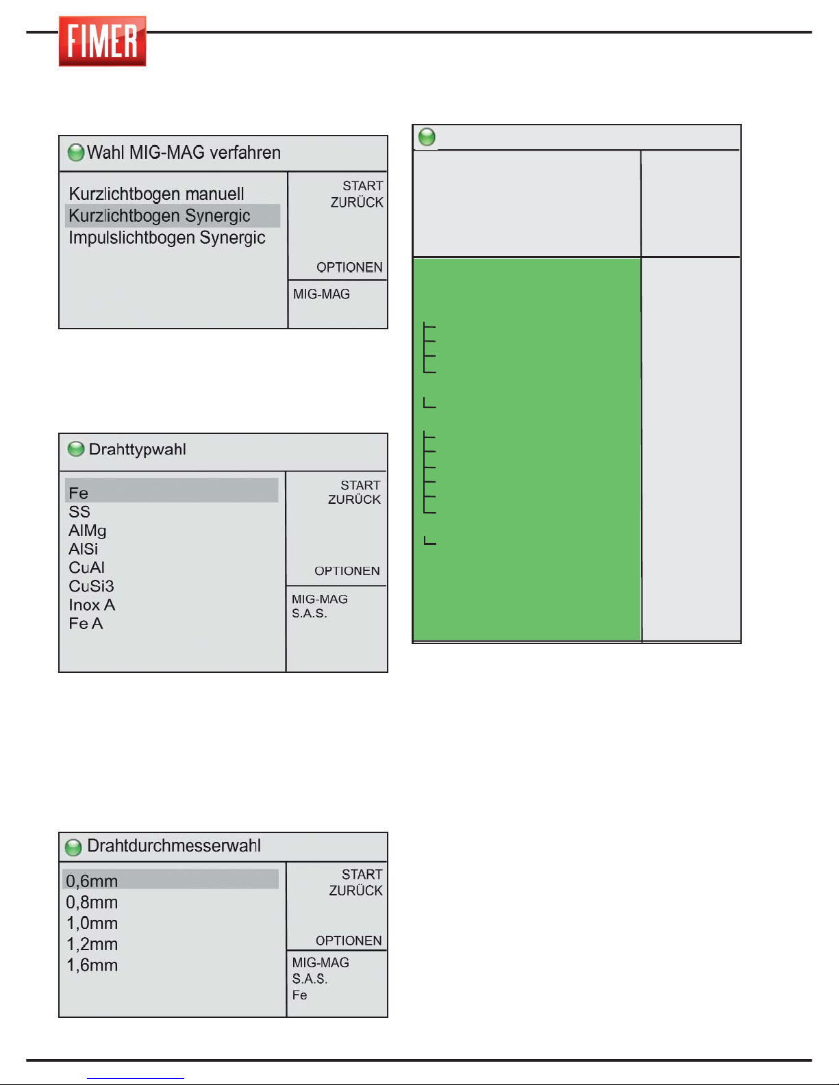
12
Durch Drehen des Drehknopfes 10 kann unter
den verschiedenen Schweißmöglichkeiten
MIG/MAG ausgewählt werden.
Drücken des Knopfes wird die Auswahl
bestätigt.
Nach der Auswahl gelangen Sie zum Display
zur Auswahl des Drahtmaterials für den
Schweißvorgang:
Die Parameter, die nicht auf dem Bildschirm
zu sehen sind, können durch Drehen des
Knopfes 10 eingesehen werden.
Nach Auswahl des Drahtes (durch Drücken des
Knopfes 10) gelangt man zur Seite, in der der
Durchmesser des Schweißdrahtes eingestellt wird.
Nach Auswahl gelangt man zum Display
„Schweißen":
E2 Lichtbogenlänge: Ermöglicht die
Regulierung der zum Schweißen verwendeten
Bezugsspannung.
Depot: Ermöglicht die Veränderung der Ablage
des Zusatzmaterials (Drahtgeschwindigkeit)
bezüglich des voreingestellten Synergiewerts.
Drossel: Ermöglicht die Änderung der
Variationsgeschwindigkeit des Schweißstroms,
um eine härteren (niedrigere Werte) und einen
weicheren (höhere Werte) Lichtbogen zu
erhalten.
Doppel-Standard: Ermöglicht die
Einschaltung (ON) oder Ausschaltung (OFF)
des Zweistufenbetriebs, d.h. die dauernde
Umschaltung zwischen zwei verschiedenen
Schweißstromstufen.
Bereit zum schweissen
START
ZURÜCK
SPEICHERN
GASSPÜLUNG
80A
23,2V
>
MIG-MAG
S.A.S.
Fe
0,6mm
E2 Lichtbogenlänge
Depot
Drossel
Doppel-Standard
E1 zeit
E2 zeit
E2 strom
E2 Volt
2/4 Takt/S-4 Takt
2. Ebene
Startstrom/Endkraterstrom
Startstrom
Startstromzeit
Slope Es->I1
Slope I1->Eek
Endkraterstrom
Endkraterstromzeit
Punktschweißen
Punkt-pause
Gasvorströmzeit
Gasnachströmzeit
Rückbrand
SoftStart/Einschleichen
Start Energie zeit
Wasserpumpe
0,0v
0,0m/’
0
OFF
0,3s
0,3s
60%
0,0v
2t
80%
OFF
125%
0,0s
0,0s
0,0s
80%
0,0s
0,0s
0,0 s
0,1 s
2,0 s
0,0 s
0
0
OFF
10,5m/'
1,8mm
Page 81
13
ESPAÑOL
FRANÇAIS
DEUTSCH
ENGLISH
ITALIANO
E1 zeit: Ermöglicht die Einstellung der Dauer
der ersten Stromstufe, wenn Zweistufenbetrieb
eingeschaltet ist.
E2 zeit: Ermöglicht die Einstellung der Dauer
der zweiten Stromstufe, wenn
Zweistufenbetrieb eingeschaltet ist.
E2 strom: Ermöglicht die Einstellung der
zweiten Stromstufe (L2) bezüglich der ersten
Stromstufe (Stufe L1), wenn Zweistufenbetrieb
eingeschaltet ist.
E2 Volt: Ermöglicht die Regulierung der
Spannung der zweiten Stromstufe (L2)
unabhängig von der Spannung der Stufe L1,
wenn Zweistufenbetrieb eingeschaltet ist
(Parameter Bogenlänge).
2/4 Takt/S-4 Takt: Ermöglicht die Einschaltung
des Zweitakt- oder Viertakt-Betriebs.
2T: Im Zweitaktbetrieb schweißt das Geräte so
lange die Taste des Handstücks gedrückt wird.
4T: Im Viertaktbetrieb beginnt das Schweißen
beim ersten Druck auf die Taste des
Handstücks, ein zweiter Druck bewirkt das
Ende des Schweißens.
4Bi: Die Funktionsweise ist wie im
Viertaktbetrieb mit dem einzigen Unterschied,
dass ein kurzes Drücken (< 1s) der Taste des
Handstücks beim Schweißvorgang den Übergang zwischen erster Stromstufe l1 und zweiter
Stromstufe l2 bewirkt, ein längeres Drücken (>
1 s) bewirkt den Beginn der Endphase des
Schweißvorgangs.
2. Ebene: Ermöglicht die Einstellung der
Stromstärke in Bezug zur zweiten
Leistungsstufe, aktiv wenn der Parameter 2T4T-4Bi auf 4Bi gestellt wird.
Startstrom/Endkraterstrom: Ermöglicht das
Einschalten (ON) oder Ausschalten (OFF) des
Betriebs mit Anfangs-/Endstrom.
Startstrom: Ermöglicht die Einstellung der
Anfangsstufe als Prozentsatz des
Schweißstroms (z.B. 130% bedeutet ls =
1,30xl1).
Startstromzeit: Ermöglicht im Zweitaktbetrieb
die Einstellung der Dauer des Anliegens des
Anfangsstroms ls.
Slope Es->I1: Ermöglicht die Einstellung der
Dauer der Anstiegszeit vom Anfangsstroms ls
zum Schweißstrom l1.
Slope I1->Eek: Ermöglicht die Einstellung der
Dauer der Absenkzeit vom Schweißstrom l1
zum Endstrom le.
Endkraterstrom: Ermöglicht die Einstellung
des Endstroms als Prozentsatz des
Schweißstroms (z.B. 80% bedeutet lf = 0,80xl1).
Endkraterstromzeit: Ermöglicht im
Zweitaktbetrieb die Einstellung der Dauer des
Anliegens des Endstroms lf.
Punktschweißen: Ermöglicht die Einstellung
(falls ≠ 0) der Höchstdauer des Schweißens.
Punkt-pause: Ermöglicht die Einstellung (falls ≠
0) der Dauer des Intervalls zwischen zwei
Punktschweißvorgängen.
Gasvorströmzeit: Ermöglicht die
Einstellung der Dauer der Gasausströmung
vor dem Zünden des Lichtbogens.
Gasnachströmzeit: Ermöglicht die
Einstellung der Dauer der Gasausströmung
nach Ende der Abgabe des Schweißstroms.
Rückbrand: Ermöglicht die Regulierung des
Drahtrückbrands nach Beendigung des
Schweißvorgangs.
SoftStart/Einschleichen: Ermöglicht die
Änderung der Vorschubgeschwindigkeit des
Drahts, so dass eine sanfte Schweißzündung
erfolgt, je höher der Wert, desto niedriger die
Vorschubgeschwindigkeit.
Start Energie zeit: Ermöglicht die Einstellung
des Zündstroms des Schweißvorgangs, so
dass der Schweißvorgang weich anläuft, in der
Regel zur Verwendung zusammen mit dem
Parameter Soft-Start.
Wasserpumpe: Ermöglicht das Einschalten
(ON) oder Ausschalten (OFF) des
Wasserkühlers, falls vorhanden.
Page 82
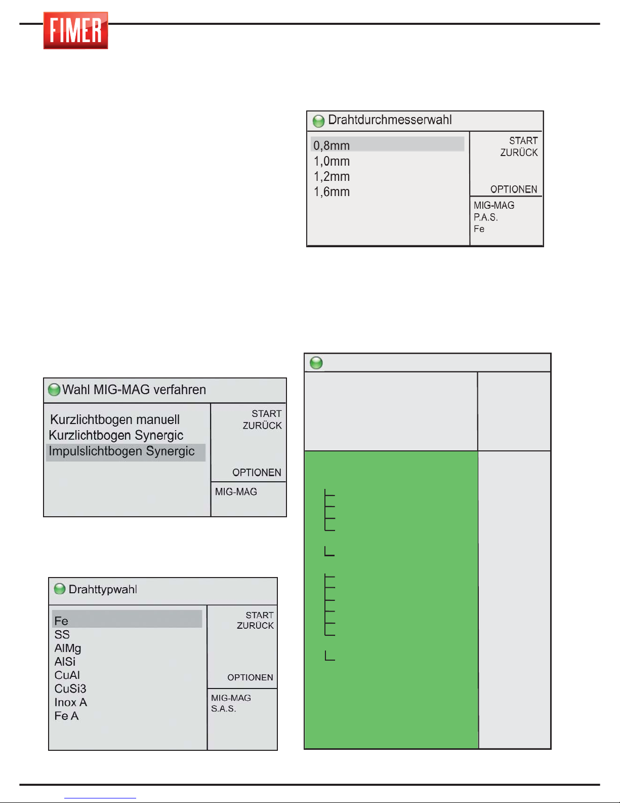
14
4.3 MIG SCHWEISSEN synergisch mit
pulsierendem Bogen
Das MIG Schweißen mit synergischem pulsierendem Lichtbogen erzeugt ein relativ kaltes
Schweißbad zusammen mit einer guten
Penetration. Dieses Schweißverfahren eignet sich
dank des niedrigen Energieeinsatzes für sehr
dünnes Material wie Edelstahl und Aluminium.
Während des Schweißvorgangs mit synergic
Regulierung reguliert der Drehknopf 9 der
Abb. 1 die Geschwindigkeit des Drahtes (also
die Schweißpotenz).
Alle anderen Parameter werden automatisch
an die eingestellte Potenz angepasst, je nach
Art und Dicke des ausgewählten Drahtes.
Nach Auswahl des Drahtes (durch Drücken des
Knopfes 10) gelangt man zur Seite, in der der
Durchmesser des Schweißdrahtes eingestellt wird.
Durch Drücken des Knopfes wird die
Auswahl bestätigt.
Nach der Auswahl gelangen Sie zum Display
zur Auswahl des Drahtmaterials für den
Schweißvorgang:
Die Parameter, die nicht auf dem Bildschirm
zu sehen sind, können durch Drehen des
Knopfes 10 eingesehen werden.
Nach Auswahl des Drahtes (durch Drücken
des Knopfes 10) gelangt man zur Seite, in
der der Durchmesser des Schweißdrahtes
eingestellt wird.
Der Drahtdurchmesser könnte nicht für alle
Modelle verfügbar sein. Nach Auswahl
gelangt man zum Display „Schweißen":
Bereit zum schweissen
START
ZURÜCK
SPEICHERN
GASSPÜLUNG
150A
30,7V
>
MIG-MAG
A.P.S.
Fe
0,8mm
Lichtbogenlänge
Depot
Doppel-Puls
E1 zeit
E2 zeit
E2 strom
E2 Lichtbogenlänge
2/4 Takt/S-4 Takt
2. Ebene
Startstrom/Endkraterstrom
Startstrom
Startstromzeit
Slope Es->I1
Slope I1->Eek
Endkraterstrom
Endkraterstromzeit
Punktschweißen
Punkt-pause
Gasvorströmzeit
Gasnachströmzeit
Rückbrand
SoftStart/Einschleichen
Start Energie zeit
Drossel
Wasserpumpe
0,0v
0,0m/’
OFF
0,3s
0,3s
60%
0,0v
2t
80%
OFF
125%
0,0s
0,0s
0,0s
80%
0,0s
0,0s
0,0s
0,1 s
2,0 s
0,0
0
0
0
OFF
14,8m/'
5,0mm
Page 83
15
ESPAÑOL FRANÇAIS
DEUTSCH
ENGLISH
ITALIANO
Lichtbogenlänge: Ermöglicht die
Regulierung der zum Schweißen
verwendeten Bezugsspannung.
Depot: Ermöglicht die Veränderung der Ablage
des Zusatzmaterials (Drahtgeschwindigkeit)
bezüglich des voreingestellten Synergiewerts.
Doppel-Puls: Ermöglicht die Einschaltung
(ON) oder Ausschaltung (OFF) des
Zweistufenbetriebs, d.h. die dauernde
Umschaltung zwischen zwei verschiedenen
Schweißstromstufen.
E1 zeit: Ermöglicht die Einstellung der Dauer
der zweiten Stromstufe, wenn
Zweistufenbetrieb eingeschaltet ist.
E2 zeit: Ermöglicht die Einstellung der Dauer
der zweiten Stromstufe, wenn
Zweistufenbetrieb eingeschaltet ist.
E2 strom: Ermöglicht die Einstellung der zweiten
Stromstufe (L2) bezüglich der ersten Stromstufe
(Stufe L1), wenn Zweistufenbetrieb eingeschaltet ist.
E2 Lichtbogenlänge: Ermöglicht die
Regulierung der Bogenlänge der zweiten
Stromstufe (L2) unabhängig von der Bogenlänge
der Stufe L1, wenn Zweistufenbetrieb
eingeschaltet ist (Parameter Bogenlänge).
2/4 Takt/S-4 Takt: Ermöglicht die Einschaltung
des Zweitakt- oder Viertakt-Betriebs.
2T: Im Zweitaktbetrieb schweißt das Geräte so
lange die Taste des Handstücks gedrückt wird.
4T: Im Viertaktbetrieb beginnt das
Schweißen beim ersten Druck auf die Taste
des Handstücks, ein zweiter Druck bewirkt
das Ende des Schweißens.
4Bi: Die Funktionsweise ist wie im Viertaktbetrieb
mit dem einzigen Unterschied, dass ein kurzes
Drücken (< 1s) der Taste des Handstücks beim
Schweißvorgang den Übergang zwischen erster
Stromstufe l1 und zweiter Stromstufe l2 bewirkt,
ein längeres Drücken (> 1 s) bewirkt den
Beginn der Endphase des Schweißvorgangs.
2. Ebene: Ermöglicht die Einstellung der
Stromstärke in Bezug zur zweiten
Leistungsstufe, aktiv wenn der Parameter
2T-4T-4Bi auf 4Bi gestellt wird.
Startstrom/Endkraterstrom: Ermöglicht das
Einschalten (ON) oder Ausschalten (OFF) des
Betriebs mit Anfangs-/Endstrom.
Startstrom: Ermöglicht die Einstellung der
Anfangsstufe als Prozentsatz des Schweißstroms
(z.B. 130% bedeutet ls = 1,30xl1).
Startstromzeit: Ermöglicht im
Zweitaktbetrieb die Einstellung der Dauer
des Anliegens des Anfangsstroms ls.
Slope Es->I1: Ermöglicht die Einstellung der
Dauer der Anstiegszeit vom Anfangsstroms
ls zum Schweißstrom l1.
Slope I1->Eek: Ermöglicht die Einstellung
der Dauer der Absenkzeit vom
Schweißstrom l1 zum Endstrom lf.
Endkraterstrom: Ermöglicht die Einstellung
des Endstroms als Prozentsatz des
Schweißstroms (z.B. 80% bedeutet lf = 0,80xl1).
Endkraterstromzeit: Ermöglicht im
Zweitaktbetrieb die Einstellung der Dauer
des Anliegens des Endstroms lf.
Punktschweißen: Ermöglicht die Einstellung
(falls ≠ 0) der Höchstdauer des Schweißens.
Punkt-pause: Ermöglicht die Einstellung
(falls ≠ 0) der Dauer des Intervalls zwischen
zwei Punktschweißvorgängen.
Gasvorströmzeit: Ermöglicht die
Einstellung der Dauer der Gasausströmung
vor dem Zünden des Lichtbogens.
Gasnachströmzeit: Ermöglicht die
Einstellung der Dauer der Gasausströmung
nach Ende der Abgabe des Schweißstroms.
Rückbrand: Ermöglicht die Regulierung des
Drahtrückbrands nach Beendigung des
Schweißvorgangs.
SoftStart/Einschleichen: Ermöglicht die
Änderung der Vorschubgeschwindigkeit des
Drahts, so dass eine sanfte Schweißzündung
erfolgt, je höher der Wert, desto niedriger die
Vorschubgeschwindigkeit.
Start Energie zeit: Ermöglicht die Einstellung
des Zündstroms des Schweißvorgangs, so
dass der Schweißvorgang weich anläuft, in der
Regel zur Verwendung zusammen mit dem
Parameter Soft-Start.
Drossel: Ermöglicht die Änderung der
Variationsgeschwindigkeit des
Schweißstroms, um eine härteren
(niedrigere Werte) und einen weicheren
(höhere Werte) Lichtbogen zu erhalten.
Wasserpumpe: Ermöglicht das Einschalten
(ON) oder Ausschalten (OFF) des
Wasserkühlers, falls vorhanden.
Page 84
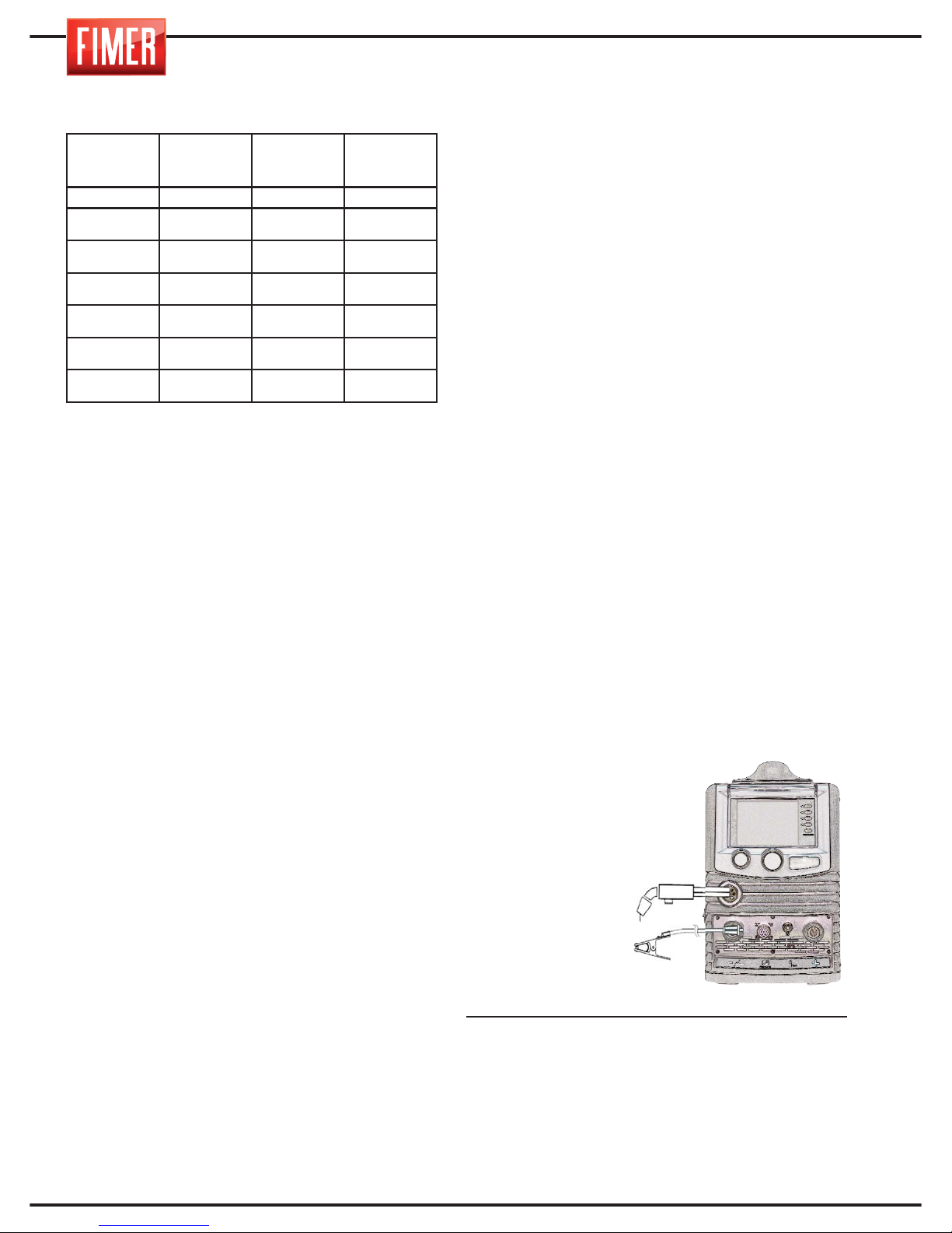
16
Für die Einstellung der korrekten Schweißstromstärke siehe nachfolgende Tabelle:
5. VERBINDUNGEN FÜR MIG-SCHWEISSEN
Die Verbindung der Schweißkabel erfolgt
über ein Schnellverbindungssystem mit
speziellen Verbindungsstücken.
5.1. MIG-BRENNER
Wir weisen darauf hin, regelmäßige
Überprüfungen des Brennerkopfes
vorzunehmen, dabei sind auch die Gasdüse
(Abb. 4A), die Drahtführungsspitze (Abb. 4B),
und die Brennerinnenverkleidung zu kontrollieren.
Diese Teile müssen stets sauber und
unbeschädigt sein. Ersetzen Sie die
Drahtführung, sollte der Draht nicht
ordnungsgemäß abspulen.
Anmerkung: Jedem Draht und Durchmesser
entspricht eine bestimmte Drahtführungsspitze
und Verkleidung. Überprüfen Sie, dass es
sich um die richtigen handelt.
5.2 ANSCHLUSS FÜR MIG SCHWEISSEN
traditionellem Brenner
1) Verbinden Sie das Massenkabel mit der
vorgesehenen Buchse „-" im Vorderbereich (12
der Abb.1). Bei Einstecken muss der Stecker
mit den Einkerbungen ausgerichtet werden und
die Buchse über Drehen im Uhrzeigersinn
festgezogen werden. Nicht zu fest ziehen!
2) Verbinden Sie den Brennerkopf mit dem
vorgesehenen Halter auf der Vorderseite (16
der Abb.1) und ziehen Sie ihn durch Drehen
im Uhrzeigersinn fest. Nicht zu fest ziehen!
Achtung: Das Gerät wird mit serienmäßig mit
seinem eigenen MIG Schweißbrenner geliefert
(Abb. 4). Dieses Teil wird bei regelmäßigen
Kontrollen der Gasdüse (Abb. 4A) und der
Drahtführungsspitze (Abb. 4B) eine lange
Haltbarkeit haben. Diese Teile müssen stets
sauber und unbeschädigt sein. Ersetzen Sie die
Drahtführung, sollte der Draht nicht
ordnungsgemäß abspulen.
5.3 ANSCHLUSS FÜR MIG SCHWEISSEN
mit Gas und Brenner Push-pull
1) Verbinden Sie das Massenkabel mit der
vorgesehenen Buchse „-" (12 der Abb.1).
Bei Einstecken muss der Stecker mit den
Einkerbungen ausgerichtet werden und über
Drehen im Uhrzeigersinn festgezogen
werden. Nicht zu fest ziehen!
2) Verbinden Sie den Brennerkopf mit dem
vorgesehenen Halter auf der Vorderseite (16
der Abb.1) und ziehen Sie ihn durch Drehen
im Uhrzeigersinn fest. Nicht zu fest ziehen!
3) Verbinden Sie den Stecker der
Brennerkopfsignale mit der vorgesehenen
Öffnung.
MIG SCHWEISSEN:
Verbinden Sie den Druckminderer mit der
Gasflasche und anschließend den Gasschlauch des Brenners mit dem Druckminderer.
MIG Schweißarbeiten werden normalerweise in c.c. mit Pluspol ausgeführt („+" siehe
Abb. 5).
Das Kabel des
Brennerkopfes MIG
wird mit dem Eurostecker verbunden
(16 Abb.1), während das Massenkabel des
Arbeitsstücks mit
dem Fronststecker
„-” zu verbinden ist
(12 Abb.1).
Nun kann die Schweißstromstärke über das
Potentiometer (9 Abb. 1) auf dem Vorderpaneel eingestellt werden.Der Durchmesser
der Elektrode und der Wert des Schweißstroms sind je nach Dicke des Arbeitsstück
auszuwählen.
DICKE DES
ARBEITS-
STÜCKS
DRAHTDUR-
CHMESSER
SCHWEISS-
STROM-
STÄRKE
BOGEN
mm mm A
0.8 - 1.0 0.6 - 0.8 60-100
Short-Arc
1.5 - 2.0 0.8 - 1.0 80-120
Short-Arc
2.0 - 3.0 1.0 - 1.2 100-130
Short-Arc
3.0 - 4.0 1.2 120-200
Short-Arc
> 4.0 1 150÷200
Spray-Arc
> 4.0 1.2 200÷300
Spray-Arc
Fig.5
Page 85
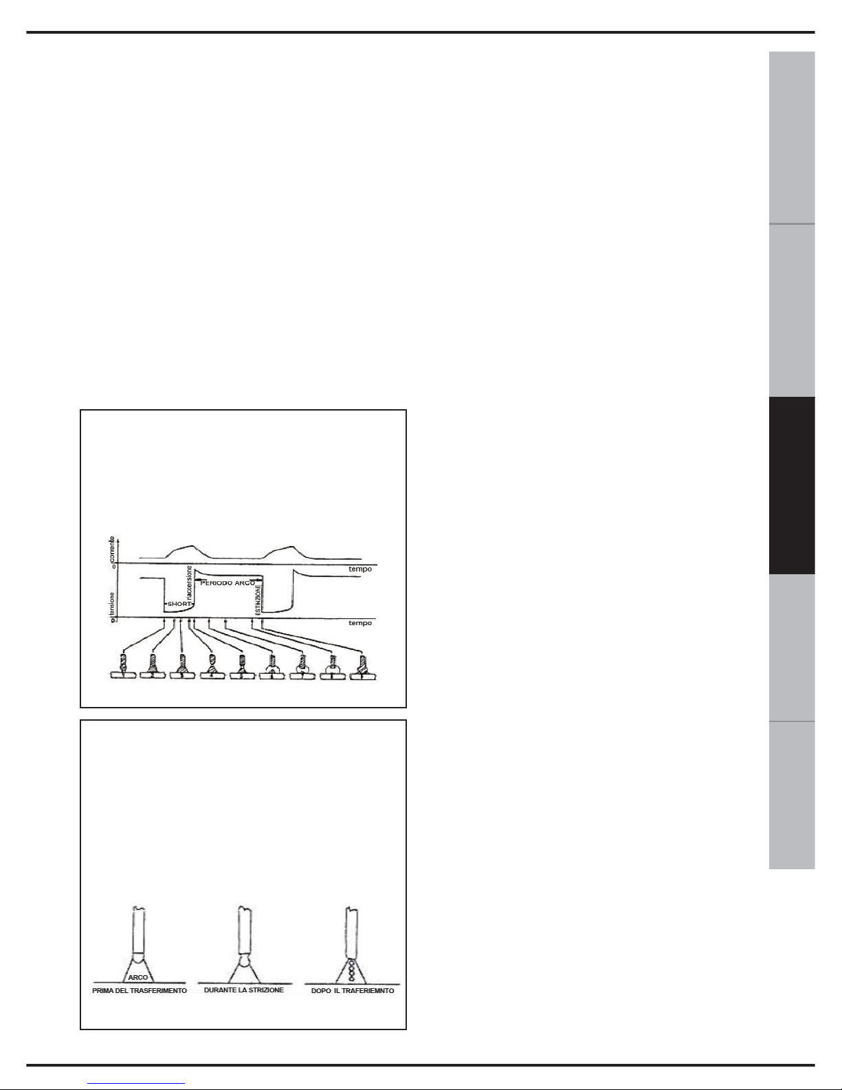
17
ESPAÑOL FRANÇAIS
DEUTSCH
ENGLISH
ITALIANO
6. ERZEUGEN DES LICHTBOGENS BEIM
MIG-SCHWEISSEN
Der Schweißvorgang MIG-MAG wird durch
einen elektrischen Bogen erzeugt, der sich
zwischen einem Schmelzdraht und dem
Arbeitsstück unter einem Schutzgas bildet.
Dies kann eine inerte Atmosphäre sein (Argon)
oder aber eine aktive Atmosphäre (CO² oder
eine Mischung aus Argon und CO²). Der Draht
wird kontinuierlich über die Drahtspulen durch den Brenner bis zum Schmelzbad vorgerückt. Es kann Volldraht oder aber Fülldraht
verwendet werden.
Die Art und Weise, wie das Schweißmaterial
übertragen wird, bestimmt die verschieden
Bogentypen:
- Die Spannung beeinflusst direkt das Aussehen der Naht. Die Abmessungen der Oberfläche können jedoch je nach Anforderungen
verändert werden, dabei ist manuell auf den
Brenner einzuwirken, um variable Ablagerungen bei gleicher Spannung zu erhalten.
- Die Geschwindigkeit des Drahts erfolgt im
Verhältnis zur Schweißstromstärke.
7. EINSTELLUNG DES
SCHWEISSGERÄTS
Nachdem die Spannung eingestellt wurde, ist
der Bogen auf einer Länge von 5-10 mm zu
halten und die Geschwindigkeit des Drahts zu
regulieren, um ein perfektes Ergebnis zu erhalten. Es empfiehlt sich, eine Schweißprobe auf
einem von Ablagerungen, Rost oder Lack
befreitem Arbeitsstück vorzunehmen.
ANMERKUNG Durch Drücken des Schalters
auf dem Brenner werden die folgenden drei
Funktionen festgelegt:
- Gasfluss
- Drahtvorschub
- Schweißstromstärke
8. FÜR BESTE SCHWEISSERGEBNISSE
1. Neigen Sie den Brennerkopf um 45° zum
Schweißmaterial. Halten Sie die Gasdüse
(Abb. 4A) etwa 6 mm vom Arbeitsstück
entfernt.
2. Bewegen sie den Brennerkopf
gleichmäßig. So wird der Gasschutz des
Bogens gewährleistet.
3. Meiden Sie Schweißarbeiten bei starkem
Wind. Starker Wind kann das Gas davonblasen
und zu einer porösen Schweißarbeit führen.
4. Halten Sie den Draht sauber: Verwenden
Sie keinen rostigen Draht.
5. Vermeiden Sie Knicke oder Spiralen am
Brennerkopfkabel. Sie können den
Drahtfluss stören.
6. Beim Auswechseln der Spule reinigen Sie
die Drahtröhre mit Druckluft.
SHORT ARC (Übertragung mit Kurzschluss):
Die Elektrode kommt in direkten Kontakt mit
dem Schweißbad, womit ein Kurzschluss mit
gleichzeitigem Schmelzvorgang des Drahts
erzeugt wird. Der Draht wird unterbrochen,
woraufhin der Bogen sich erneut entzündet und
der Zyklus von vorn beginnt.
SPRAY ARC (Sprüh-Übertragung): Die Tropfen lösen sich von der Elektrode und erreichen
anschließend das Schmelzbad.
Die Sichtbarkeit des Bogens reduziert ein genaues
Einhalten der Regulierungstabellen durch den
Arbeiter. Dieser kann direkt das Schmelzbad
beobachten.
Page 86
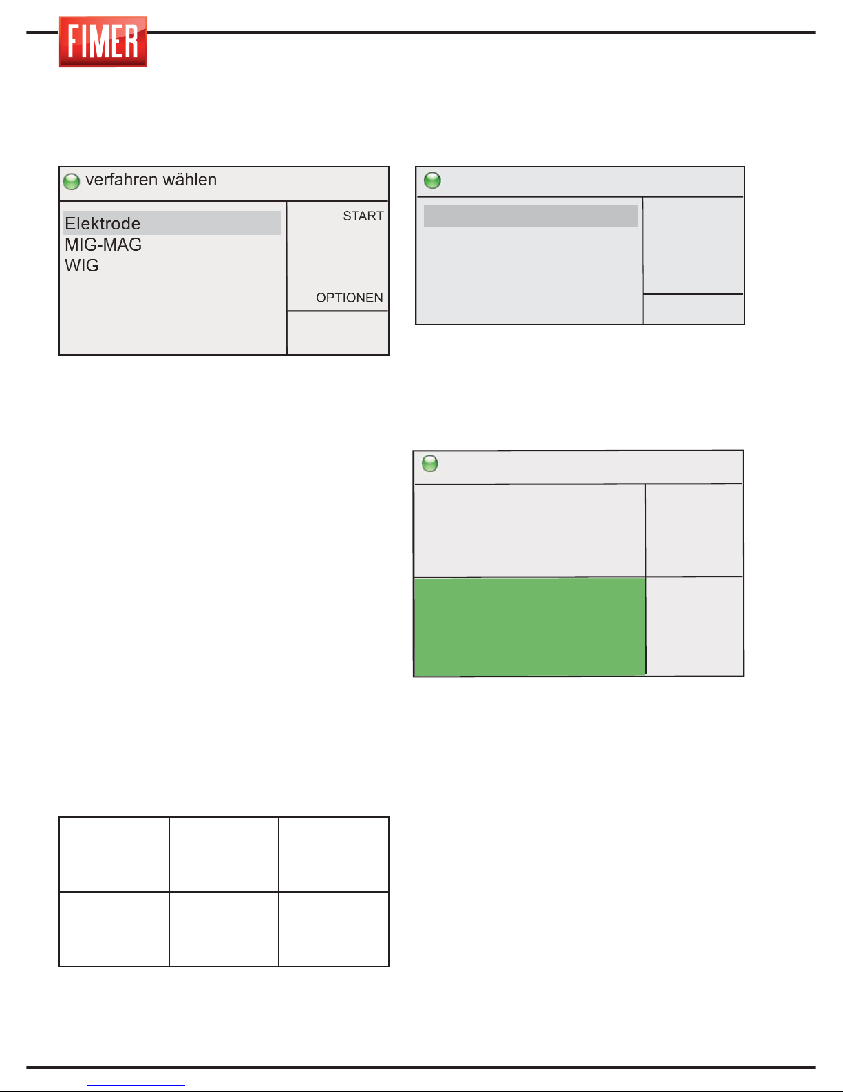
18
9. MMA SCHWEISSEN
Zur Auswahl dieser Schweißtechnik:
Über den Drehknopf 10 wählen Sie MMA
und drücken Sie ENTER
Elektrode (Metal Manual Arc) oder SMAW
(Shielded Metal Arc Welding) ist ein
manuelles Schweißverfahren, welches die
über einen Lichtbogen, der zwischen einer
Schmelzelektrode zum Schweißstück reicht,
erzeugte Hitze nutzt. Dieser Verfahren
gestattet es, in jeder Position Nähte zu
erzeugen: In der Werkstatt, in Freien, in
engen oder schwer zugänglichen Bereichen.
Mit den TM 236 können jede Art von
Elektrode und jeder Durchmesser
verschweißt werden. Der Bogen wird
erzeugt, indem die Elektrode an das
Werkstück angenähert wird.
Die Verbindungsstromstärke des
Brennerkopfs und des Massenkabels wird in
der nachfolgenden Tabelle angegeben.
Stellen Sie zudem sicher, dass Masse und
Elektrodenzange gut voneinander entfernt sind.
9.1 MANUELLES MMA SCHWEISSEN
Man gelangt zu diesen Einstellungen über die
Auswahl durch Druck auf den Drehknopf 10.
Nach Auswahl gelangt man zum Display
„Schweißen":
Über den Drehknopf 9 in Abb. 1 kann die
Schweißstromstärke eingestellt werden
(dickere Schweißstücke benötigen eine
höhere Stromstärke).
Über den Drehknopf 10 können die anderen
in der Abbildung gezeigten Parameter
eingestellt werden:
EINSTELLUNG UND PARAMETER:
Über den Drehknopf 10 können die im
Display angezeigten Schweißparameter
eingestellt werden:
Arc-Force: Ermöglicht die Einstellung des
Stromanstiegs als Prozentsatzes des
Schweißstroms, die das Schweißgerät
automatisch reguliert, um einen
regelmäßigen Bogen beizubehalten.
Hot Start: Ermöglicht die Einstellung des
Stromanstiegs als Prozentsatzes des
Schweißstroms, die das Schweißgerät
automatisch reguliert, um den Bogen zu
zünden.
Zeit Hot Start: Ermöglicht die Einstellung der
Dauer der automatischen Hot-StartStromregulierung.
Fernsteuerung: Ermöglicht das Einschalten
(ON) oder Ausschalten (OFF) der
Fernsteuerung der abgegeben Stromstärke.
SCHWEISSPRO-
ZESS
Frontstecker
+
14 Abb.1
Frontstecker
-
12 Abb.1
MMA
ELEKTRODEN-
STECKER
MASSENKABEL
Wahl MMA Verfahren
START
ZURÜCK
OPTIONEN
MMA
Manuell
Bereit zum schweissen
START
ZURÜCK
SPEICHERN
OPTIONEN
arc force
hot start
Zeit Hot Start
Fernsteuerung
20%
20%
0.5s
OFF
Elektrode
Manuell
150
A
15,0
V
>
Page 87
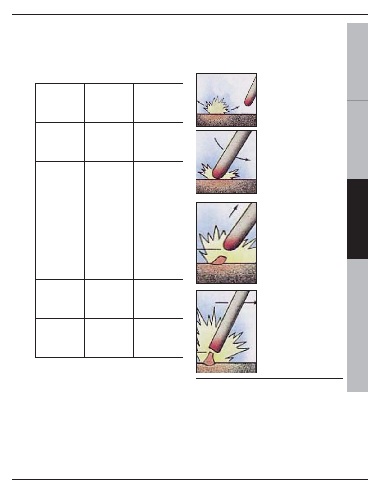
19
ESPAÑOL FRANÇAIS
DEUTSCH
ENGLISH
ITALIANO
10. SCHWEISSTABELLE
Über die nachfolgende Tabelle können Sie die
Schweissstromstärke je nach verwendeter
Elektrode berechnen.
11. ANSCHLUSS FÜR MMA
SCHWEISSEN
Bei Einstecken muss der Dinse-Stecker
mit den Einkerbungen ausgerichtet
werden und über Drehen im Uhrzeigersinn
festgezogen werden.
Elektroden- und Massenzange sind an die
Pole „+" und „-" anzuschließen, je nach
Angaben auf der Verpackung der
verwendeten Elektroden.
12. ERZEUGEN DES
LICHTBOGENS BEI MMA
AUSSCHALTEN
Verweilen Sie einen Moment auf dem
Endkrater (also dem Ende der Schweißnaht),
kehren Sie anschließend langsam etwa 2 cm
auf der Naht zurück und entfernen Sie nun
erst die Elektrode vom Arbeitsstück, damit
der Bogen erlischt.
ELEKTRODEN-
DURCHMES-
SER
SCHWEISS-
STROM-
STÄRKE
LÄNGE DER
ELEKTRODE
mm A mm
2.0 45 ÷ 60
300
2.5 60 ÷ 100
300
3.25 90 ÷ 140
450
4.0 140 ÷ 170
450
5.0 190 ÷ 230
450
Erzeugen Sie den Kontakt
zum Zünden des Bogens
etwa 5 cm vom
festgesetzten Beginn der
Schweißnaht entfernt.
Nähern Sie die Elektrode
sofort an das Arbeitsstück
an, ohne es zu berühren,
damit der Bogen gezündet
bleibt.
Bewegen Sie den Brenner
zügig zum festgesetzten
Beginn der Schweißnaht, um
den Bogen nicht zum
Erlöschen zu bringen.
Beginnen Sie die
Schweißarbeit, bewegen Sie
sich dabei nur langsam
vorwärts. Der Abstand
zwischen der
Elektrodenspitze und den
Arbeitsstück muss in etwa
dem Durchmesser der
verwendeten Elektrode
entsprechen.
EINSCHALTEN
Page 88
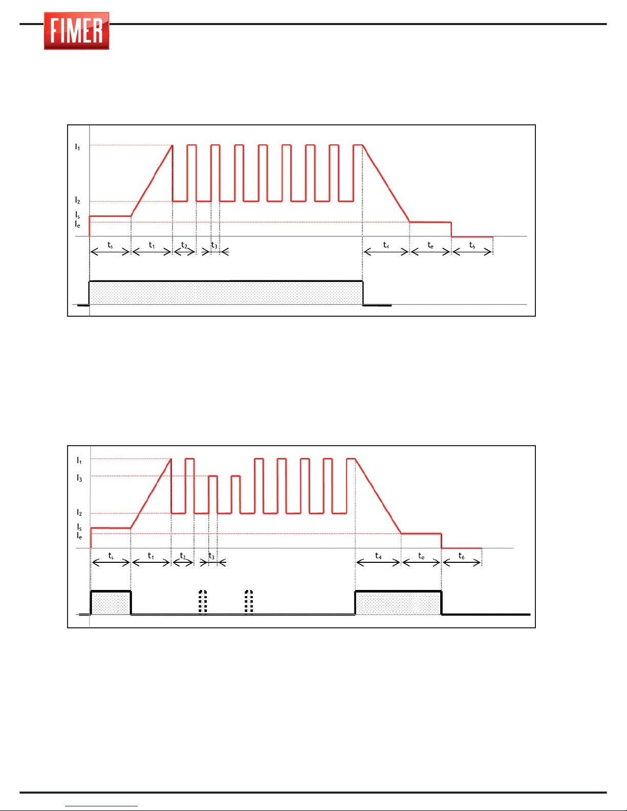
20
Um zu einem besseren Verständnis der Beschreibung der Schweißparameter berichtet, bezogen auf das WIG, wenn notwendig, auf die Trends unten machen:
Is, ts: Anfangsstrom, Anfangszeit
I
1
: Schweißstrom
I
2
: Grundstrom
I5, t5: Ende Strom, Endzeit
t
3/t2
x100: Impuls Gleichgewicht
1/t
2
: Pulsfrequenz
t
6
: Nachgaszeit
Is, ts: Anfangsstrom, Anfangszeit
I
1
: Schweißstrom
I
3
: Zweite Stromstufe
I
2
: Grundstrom
I5, I5: Ende Strom, Endzeit
t
3/t2
x100: Impuls Gleichgewicht
1/t
2
: Pulsfrequenz
t
6
: Nachgaszeit
Torch Knopf
Torch KnopfT.K.
13. WIG SCHWEISSEN
TIG 2t Modus mit Rampen
TIG 4t/4bi Modus mit Rampen
Page 89
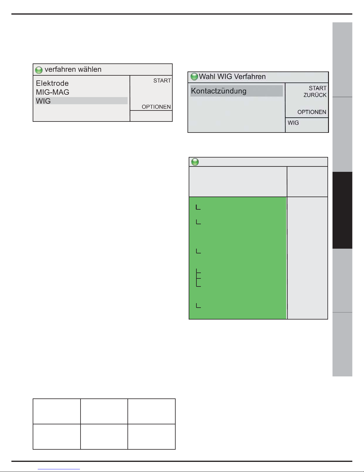
21
ESPAÑOL FRANÇAIS
DEUTSCH
ENGLISH
ITALIANO
Zur Auswahl dieser Schweißtechnik:
Über den Drehknopf 10 wählen Sie WIG
und drücken zur Bestätigung.
Das Bogenschweißen mit Inertgas und nicht
schmelzenden Wolframelektroden (TIG
Schweißen genannt: Tungsten Inertgas) ist
ein Verfahren, bei dem die Hitze über einen
Bogen erzeugt wird, der von den nicht
schmelzenden Elektroden zum Arbeitsstück
reicht. Das Schweißen geschieht, indem die
Ränder des Schweißstücks zum Schmelzen
gebracht werden oder indem eventuell aus
speziellen Stäben ein weiteres Stück zur
Nahtbildung eingesetzt wird.
Der Bogen wird erzeugt, indem das Arbeitsstück
mit der Elektrode berührt wird und anschließend
angehoben wird (LIFT Beginn).
Das WIG Schweißen eignet sich für jede
Arbeitsposition und kann auch bei Blechstücken
von geringer Dicke eingesetzt werden.
Das WIG Schweißverfahren zeichnet sich
durch seine größere Bogenkontrolle, eine
kraftvolle und konzentrierte Hitzequelle und
die einfache Kontrollmöglichkeit der
aufzutragenden Materialmenge aus.
Dies macht das WIG Verfahren besonders
geeignet für Präzisionsschweißarbeiten mit
unterschiedlicher Materialdicke, für
Schweißarbeiten in schwierigen Positionen
und auf Rohrleitungen, bei denen eine
vollständige Durchdringung erfordert wird.
Das WIG Verfahren gestattet das Schweißen
verschiedener Materialarten wie
Eisenmateriale, Legierungen aus Nickel,
Kupfer, Titan, Magnesium ...
Während des Schweißens regelt der
Potenzregler 9 der Abb. 1 die
Schweißstromstärke.
Die Verbindungsstromstärke des
Brennerkopfs und des Massenkabels wird in
der nachfolgenden Tabelle angegeben.
13.1 WIG SCHWEISSEN (Lift-Arc)
Durch Drehen des Drehknopfes 10 kann unter
den verschiedenen Schweißmöglichkeiten
WIG ausgewählt werden.
Nach Auswahl gelangt man zum Display
„Schweißen":
EINSTELLUNG UND PARAMETER:
Über den Drehknopf 10 können die im
Display angezeigten Schweißparameter
eingestellt werden:
2T-4T-4 Bilevel: Ermöglicht die Einschaltung
der Zweitakt- oder Viertakt-Betriebs.
2T: Im Zweitaktbetrieb löst der Druck auf die
Taste das Ausströmen von Schutzgas aus;
beim Abheben der Elektrode vom
Werkstück wird der Lichtbogen gezündet,
mit Ausführung des Anfangsstroms
und/oder der Anstiegszeit, der Bogen bleibt
für die gesamte Zeit, während der die Taste
gedrückt wird, bestehen. Wird sie losgelassen, beginnt die Absenkzeit des Stroms und
oder der Endstrom, falls eingestellt.
Bereit zum schweissen
START
ZURÜCK
SPEICHERN
OPTIONEN
150A
15,0V
>
WIG
Lift
2/4 Takt/S-4 Takt
I2
Startstrom
Startstromzeit
Stromanstiegszeit
Stromabsenkzeit
Endkraterstrom
Endkraterstromzeit
Gasnachströmzeit
Puls-Funktion
Puls-Basisstrom
Puls-Frequenz
Abwägung I1 zu I2
Wasserpumpe
Fernsteuerung
Min strom
Punktschweißen
2t
-50%
50%
0,0s
0,0s
0,0s
20%
0,0s
5,0s
OFF
50%
10,0
50%
OFF
OFF
10A
0,0s
SCHWEISSPRO-
ZESS
FRONTSTECKER
+
14 Abb. Fig.1
FRONTSTECKER
-
12 Abb. Fig.1
Page 90

22
4T: Im Viertaktbetrieb löst der erste Druck
auf die Taste das Ausströmen von
Schutzgas aus, beim Abheben der Elektrode
vom Werkstück wird also der Lichtbogen
gezündet.
Der abgegebene Strom entspricht dem
Parameter Anfangsstrom, so lange die Taste
gedrückt gehalten wird, dann führt das Gerät
die eingestellte Anstiegszeit aus. Bei erneutem Drücken der Taste führt das Gerät die
Strom-Absenkzeit aus, falls eingestellt und
den Endstrom (bis zum Loslassen der Taste)
und anschließend die Gasnachströmzeit.
Wird die Taste gleich losgelassen, führt das
Gerät die Absenkzeit des Stroms (falls eingestellt) und anschließend die
Gasnachströmzeit aus.
4Bi: Die Funktionsweise ist wie im
Viertaktbetrieb mit dem einzigen
Unterschied, dass ein kurzes Drücken (< 1s)
der Taste des Handstücks beim
Schweißvorgang (d.h. nach Beendigung der
Anstiegszeit) den Übergang zwischen erster
Stromstufe l1 und zweiter Stromstufe l2
bewirkt, ein längeres Drücken (> 1 s) bewirkt
den Beginn der Endphase des
Schweißvorgangs (Absenkzeit und/oder
Endstrom falls eingestellt).
Zweite Stromstufe: Falls für den Parameter
2T-4T-4Bilevel der Wert 4Bi gewählt wurde,
kann die zweite Stromstufe als Prozentsatz
des Schweißstroms eingestellt werden.
Anfangsstrom: Ermöglicht die Einstellung des
Werts, auf den der Schweißstrom gleich nach
dem Zünden des Lichtbogens gebracht wird.
Anfangszeit: Ermöglicht die Einstellung der
Zeit, für die der vom Parameter
Anfangsstrom bestimmte Strom anliegt.
In Betriebsart 4T/4Bi (falls der Parameter
Punktschweißen gleich 0 ist) hat diese Zeit
keinen Einfluss und der Anfangsstrom wird
beibehalten, so lange die Taste des
Handstücks gedrückt wird.
Anstiegszeit: Ermöglicht die Einstellung der
Dauer der Anstiegszeit des Schweißstroms.
Absenkzeit: Ermöglicht die Einstellung der
Dauer der Absenkzeit des Schweißstroms.
Endstrom: Ermöglicht die Einstellung des
Werts, auf den der Schweißstrom nach
Abschluss der Absenkzeit gebracht wird.
Endzeit: Ermöglicht die Einstellung der Zeit,
für die der vom Parameter Endstrom
bestimmte Strom anliegt.
In Betriebsart 4T/4Bi hat diese Zeit keinen
Einfluss und der Endstrom wird beibehalten, so lange die Taste des Handstücks
gedrückt wird.
Gasnachströmzeit: Ermöglicht die
Einstellung der Dauer der Gasausströmung
nach Ende der Abgabe des Schweißstroms.
Impuls: Ermöglicht die Einschaltung (Hz)
oder Ausschaltung (OFF) des
Impulsschweißens, bei eingeschaltetem
Impulsschweißen (Hz) liefert das Gerät für
einen bestimmten Zeitraum Schweißstrom
und für einen anderen Zeitraum den vom
Parameter Grundstrom bestimmten Strom.
Die Anzahl der Stromimpulse pro Zeiteinheit
wird durch den Frequenz-Parameter
bestimmt.
Die Impulse werden nur beim
Schweißvorgang erzeugt und nicht in den
Phasen des Anfangs-/Endstroms oder während der Anstiegs-/Absenkzeit.
Grundstrom: Ermöglicht die Einstellung des
anliegenden Grundstroms bei Erzeugung
der Impulse.
Frequenz: Ermöglicht die Einstellung der
Anzahl der Stromimpulse pro Zeiteinheit,
wenn Impulsschweißen eingeschaltet ist.
Balanceregelung: Stellt den Prozentsatz
der Zeit dar, für die der Schweißstrom bei
eingeschaltetem Impulsschweißen anliegt.
Wasserpumpe: Ermöglicht das Einschalten
(ON) oder Ausschalten (OFF) des
Wasserkühlers, falls vorhanden.
Fernsteuerung: Ermöglicht das Einschalten
(ON) oder Ausschalten (OFF) der
Fernsteuerung der abgegeben Stromstärke.
Mindeststrom: Ermöglicht die Einstellung
des abgegebenen Mindeststroms, wenn
die Fernsteuerung auf den Mindestwert
gestellt ist.
Punktschweißen: Ermöglicht die
Einstellung (falls ≠ 0) der Höchstdauer des
Schweißens.
Page 91
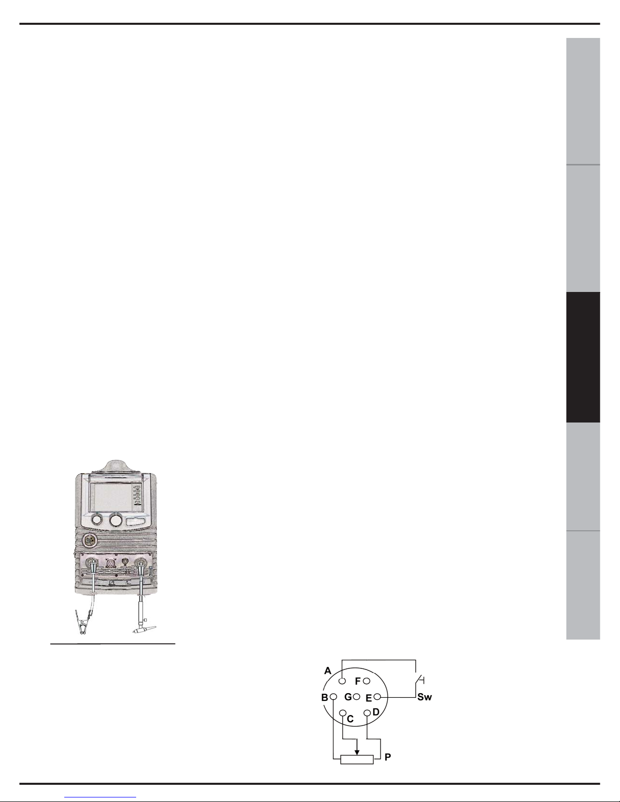
23
ESPAÑOL FRANÇAIS
DEUTSCH
ENGLISH
ITALIANO
14. ANSCHLUSS FÜR WIG
SCHWEISSEN
1) Verbinden Sie das Massenkabel mit der
vorgesehenen Buchse „+" im Vorderbereich
(14 der Abb.1). Bei Einstecken muss der
Stecker mit den Einkerbungen ausgerichtet
werden und über Drehen im Uhrzeigersinn
festgezogen werden. Nicht zu fest ziehen!
2) Verbinden Sie den Brennerkopf mit den
Halter auf der Vorderseite (12 der Abb.1).
3) Bei Einstecken muss der Stecker mit den
Einkerbungen ausgerichtet werden und über
Drehen im Uhrzeigersinn festgezogen
werden. Nicht zu fest ziehen!
4) Verbinden Sie den Signalstecker des
Brennerkopfschalters mit der vorgesehenen
Öffnung.
WIG SCHWEIßEN:
Vor dem Anschluss an die Gasflasche überprüfen Sie, ob diese reines Inertgas enthält.
Verwenden Sie kein anderes Gas.
Verbinden Sie den
Druckminderer mit
der Gasflasche und
anschließend den
Gasschlauch des
Brenners mit dem
Druckminderer.
WIG Schweißarbeiten werden normalerweise in c.c.
mit Minuspol
ausgeführt („-"
siehe Abb. 6).
Das Kabel des Brennerkopfes WIG wird
mit dem Minuspol des Generators vebunden (12 Abb.1), während das Massenkabel
des Arbeitsstücks mit Pluspol zu verbinden
ist (14 Abb.1).
Nun kann die Schweißstromstärke über das
Potentiometer (9 Abb. 1) auf dem Frontalpaneel eingestellt werden.
Der Elektrodendurchmesser und der Wert der
Stromstärke sind je nach Dicke des zu
schweißenden Materials gewählt werden.
15. NETZANSCHLÜSSE
Vor dem Verbinden mit der Stromquelle
kontrollieren Sie die Spannung, Phasenzahl
und die Frequenz der Stromversorgung.
Überprüfen Sie weiterhin, dass der gelieferte
Stecker mit den Steckdosen Ihres Landes
übereinstimmt. Stellen Sie sicher, dass die
gelieferte Stromstärke zum Betrieb des
Geräts ausreicht (Spannungsrange).
Das Gerät verfügt über ein spezielles
Netzkabel, das nicht verlängert werden
sollte. Sollte dies notwendig sein, verwenden
Sie ein Verlängerungskabel mit gleichem
oder größerem Querschnitt je nach Länge
des Kabels.
Das Dreipol- + Erdungskabel muss einen
Querschnitt von mindestens 2.5 mm²
besitzen.
16. FERNVERBINDUNG
In Abb. 7 sind die Verbindungen zum
Fernanschluss (13 der Abb. 1) angegeben.
Wo:
Sw ist der
Brennerkopfschalter
P ist der
Potenzregler für die
Überwachung der
Stromstärke.
Abb.6
Abb.7
Page 92
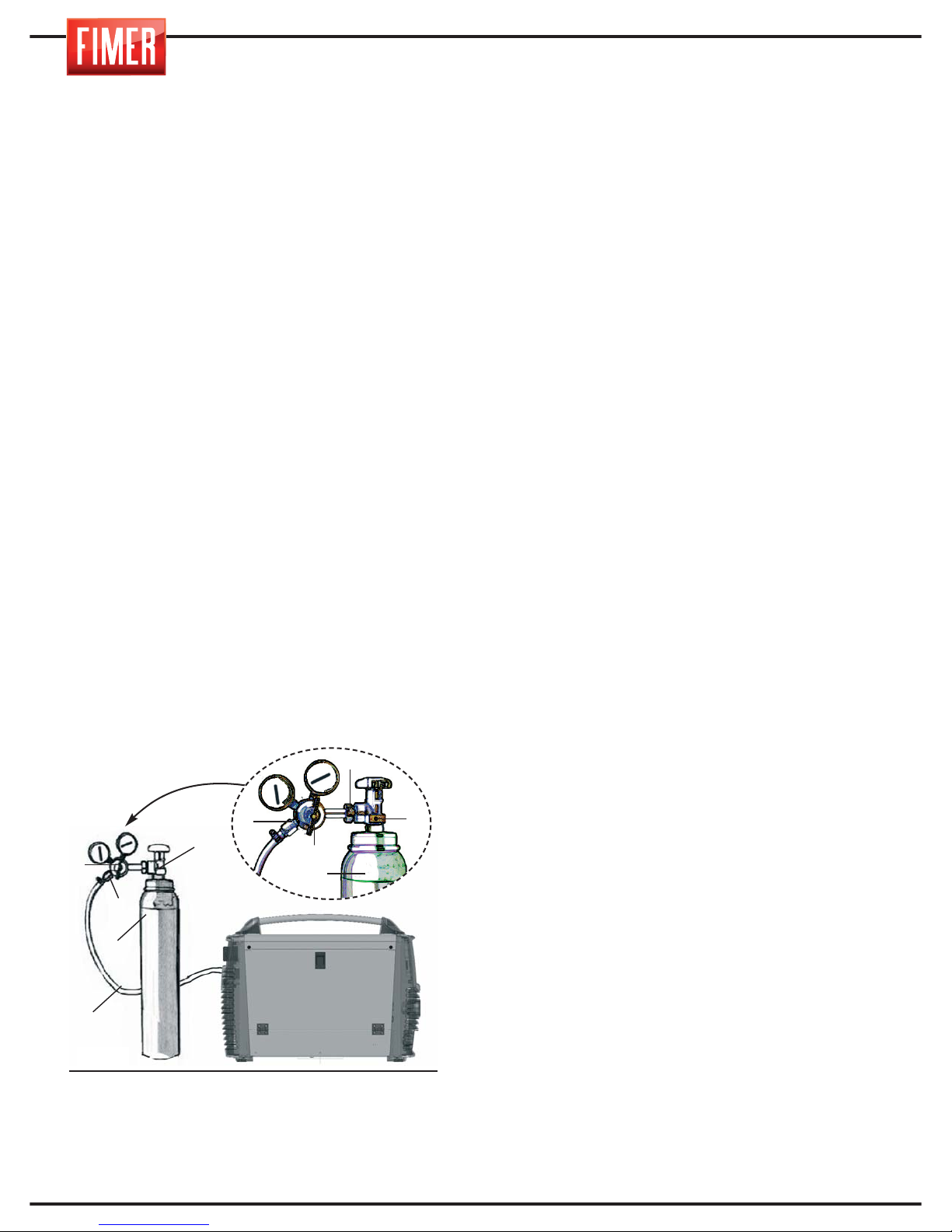
24
16.1 FERNBEDIENUNG DER
STROMSTÄRKE
Über den Fernanschluss 13 der Abb. 1 kann
die Stromstärkenreglung dicht an den
Schweißort gebracht werden. Dafür muss
eine Verbindung zum Potenzregler P der
Abb. 7 hergestellt werden. Der Wert des
Potenzreglers ist nicht kritisch: Es können
Komponenten zwischen 2.2kOhm und
10kOhm 1/2W verwendet werden.
Durch Drehen des Potenzreglers kann die
Stromstärke auf einer Bandbreite zwischen
dem minimalen Strom von der Anzeige und
der eingestellte Wert.
17. AUSGANGSANSCHLÜSSE
Die Verbindung der Schweißkabel erfolgt
über ein Schnellverbindungssystem mit
speziellen Verbindungsstücken.
18. ANSCHLUSS DER GASFLASCHE
UND DES GASREGLERS
Nur für WIG Schweißen. Sollten Sie das
Schweißverfahren MMA verwenden, dann
überspringen Sie dieses Kapitel.
1. Verbinden Sie den Druckregler (2) mit
der Gasflasche (3). Überprüfen Sie, das
der Regler dem Gasdruck der Flasche
entspricht.
Ziehen Sie die Verbindungsmutter (6) des
Reglers (2) an der Gasflasche (3) fest.
Ziehen Sie nicht zu fest an. Übermäßige
Kraft kann das Ventil (1) der Gasflasche
beschädigen.2. Verbinden Sie die Gasleitung
(4) mit dem Regler (2) und befestigen Sie
diese mit einer Rohrschelle (5).
3. Kontrollieren Sie, dass der Gasschlauch
korrekt mit dem Schweißgerät verbunden ist.
4. Öffnen Sie das Ventil (1) der Gasflasche
(3). Drücken Sie den Schalter des
Brennerkopfes und überprüfen Sie den korrekten Gasfluss.
Achtung: Die Gasflasche enthält unter
Druck stehendes Gas, mit Vorsicht behandeln. Eine unsachgemäße Handhabung
kann zu schweren Unfällen führen.
Stellen Sie die Gasflaschen nie übereinander und setzen Sie sie nie übermäßiger
Hitze, Flammen oder Funken aus. Schlagen
Sie die Gasflaschen nicht gegeneinander.
Für weitere Informationen zum Gebrauch
und der Handhabung von Gasflaschen kontaktieren Sie Ihren Lieferanten.
Achtung: Verwenden Sie die Gasflaschen
nicht, wenn sie beschädigt ist: Kontaktieren
Sie umgehend Ihren Lieferanten.
19. NORMALE WARTUNG
DES GERÄTS
Entfernen Sie regelmäßig alle drei Monate
mit schwacher Druckluft den Staub von der
Luftansaugdüse. Richten Sie den Luftstrom
vom Inneren des Geräts nach Außen, um
keinen Schmutz ins Innere des Geräts zu
blasen.
Für diese Eingriffe ist zu überprüfen, dass
das Gerät nicht mit der Stromversorgung verbunden ist.
4
3
2
1
6
2
5
1
3
5
Abb.8
Page 93
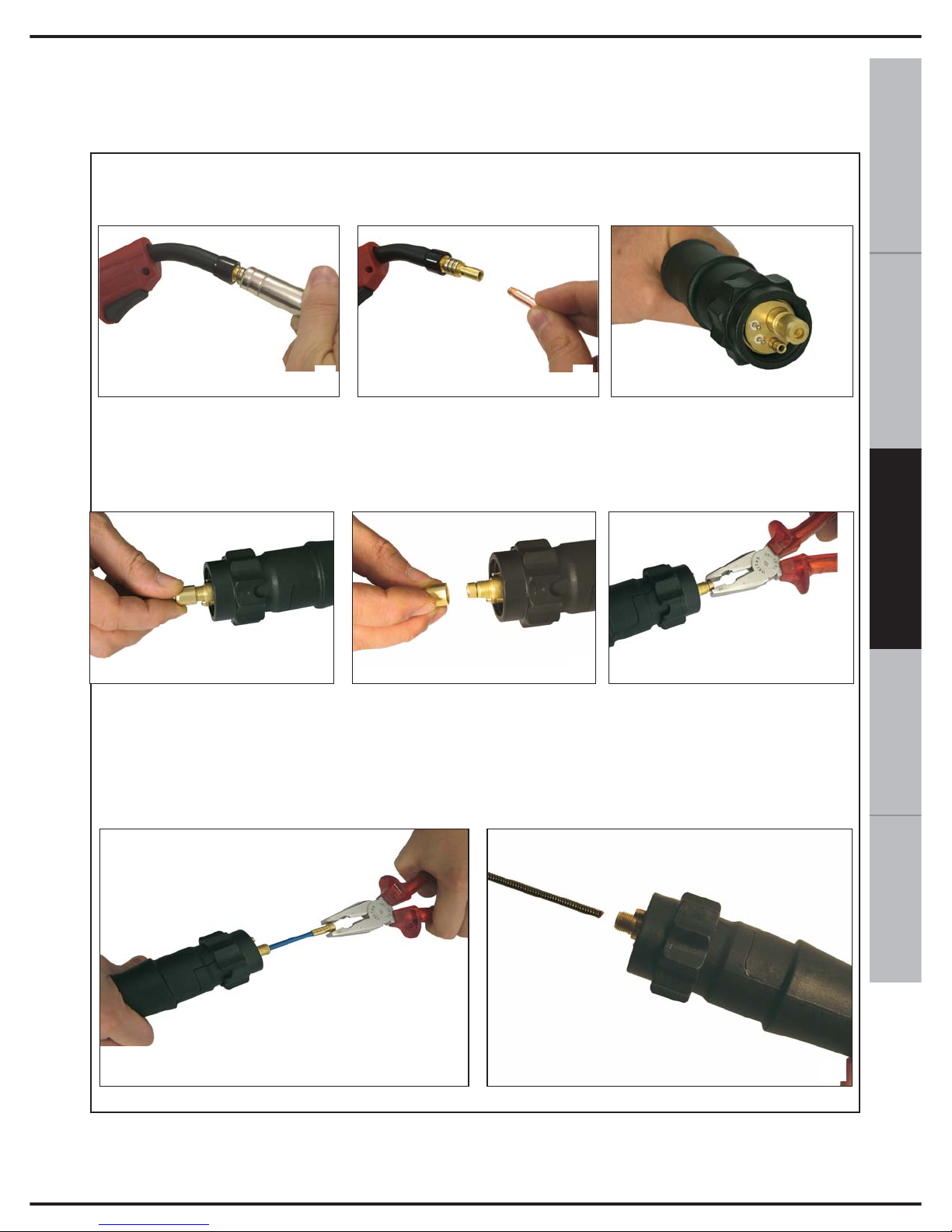
25
ESPAÑOL FRANÇAIS
DEUTSCH
ENGLISH
ITALIANO
Bei einem Austausch der Drahtkabelverkleidung folgen Sie den nachfolgenden Angaben:
• Am Brennerkopf: Entfernen Sie die Gasdüse (A).
• Schrauben Sie die Spitze der Kabelführung ab (B).
• Verbindungsseite (C): Schrauben Sie die Endmutter ab (D,E) und ziehen Sie das Ende
der Verkleidung mit einer Zange heraus (F).
• Ziehen Sie die Verkleidung vollständig heraus (G).
A
B
C
D
E
F
• Führen Sie die neue Verkleidung ein und schieben Sie sie bis ganz nach hinten (H)
• Schrauben Sie die Spitze der Kabelführung (B) wieder auf den Brennerkopf.
• Schrauben Sie die Gasdüse wieder an (A).
G
H
20. ERSATZ DER VERKLEIDUNG ZUR DRAHTFÜHRUNG IM BRENNER
Während dieses Eingriffs achten Sie darauf, den O-RING nicht zu verlieren
(Gummidichtung), die für einen festen Halt ohne Gasaustritt sorgt.
Page 94
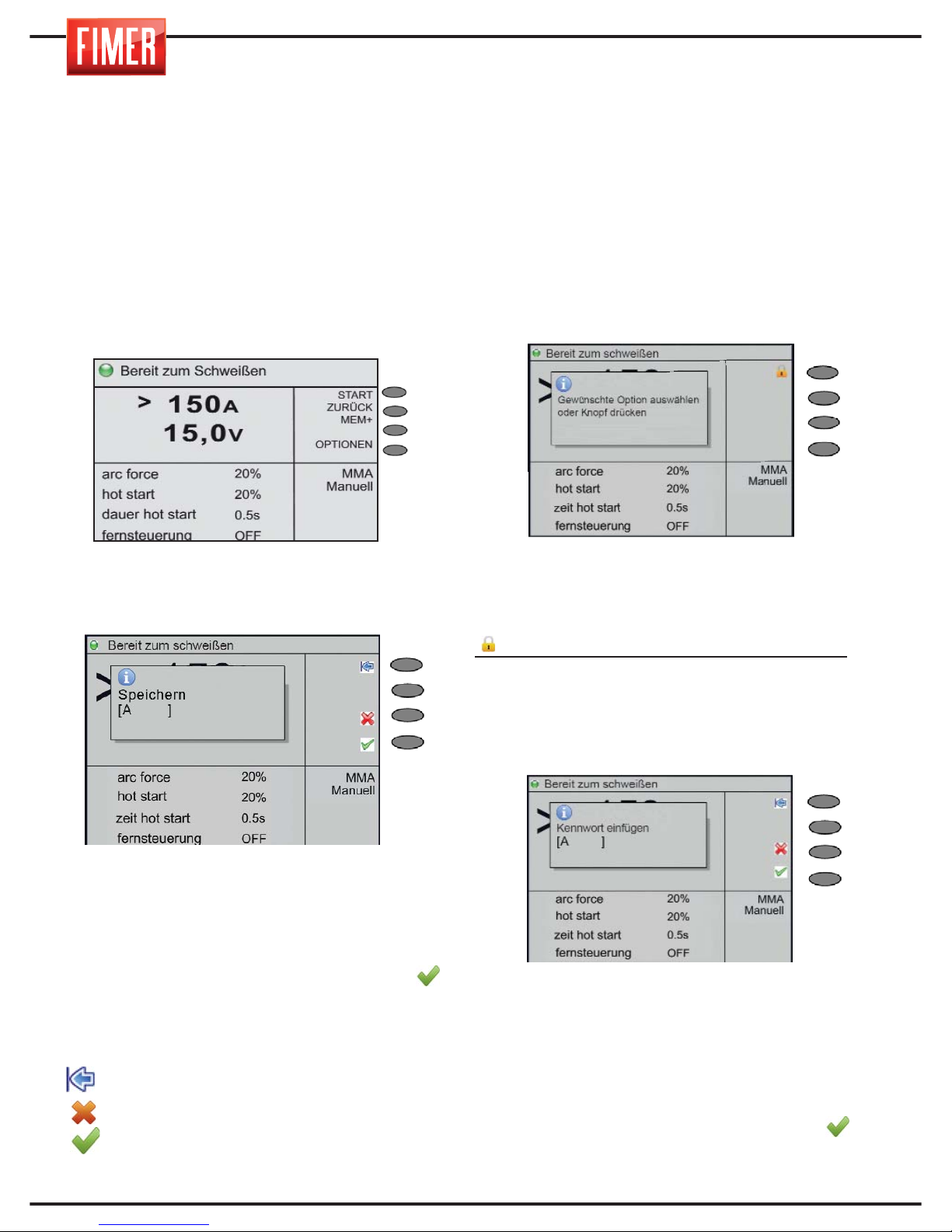
26
21. SPEICHERN DES SCHWEISSPUNKTS
Wie in den vorherigen Abschnitten aufgezeigt
gestattet das Schweißgerät, den Schweißpunkt
persönlich einzurichten (sowohl in manuell als
auch in synergisch).
Der optimale Schweißpunkt eines Arbeitsstücks
kann abgespeichert werden und anschließend
schnell erneut aufgerufen werden.
Zum Speichern eines neuen Schweißpunktes
folgen Sie den nachfolgenden Anweisungen:
1. Legen Sie die Parameter für den
Schweißvorgang fest.
2. Drücken Sie den Knopf MEM+ (4 di fig 1).
3. Drehen Sie den Knopf 10 (Abb. 1) und wählen
Sie den ersten Buchstaben des Namens,
unter dem Sie die Arbeit speichern möchten.
4. Drücken Sie den Knopf 10 zum Bestätigen
des Buchstabens.
5. Wiederholen Sie die Schritte 2 und 3 bis zum
Vervollständigen des Namens.
6. Durch Drücken des Knopfes wird der Name
bestätigt
Von diesem Moment an wird der
Schweißpunkt unter diesem Namen
gespeichert und zusammen mit allen anderen
Schweißvorgängen angezeigt.
Die Bedeutung der Knöpfe:
back sp: Löscht den letzten
eingegebenen Buchstaben.
Löschen: annulla l’operazione eseguita.
OK: Bestätigt den Namen des
Schweißpunktes.
22. SPERREN DES SCHWEISSPUNKTES
Das Schweißgerät gestattet das Sperren von
Funktionen der Knöpfe 9 und 10, so dass nach
der Speicherung eines Schweißpunkts dieser
ohne Passwort, welches vom Nutzer festgelegt
werden kann, nicht mehr verändert werden
kann. Zum Sperren des Schweißpunkts ist
dieser zunächst einmal festzulegen. Das
bedeutet, dass alle Parameter für das
gewünschte Schweißergebnis
vorprogrammiert werden müssen.
Sobald dies geschehen ist, wird
folgendermaßen vorgegangen:
1. Drücken Sie den Knopf 9 der Abb. 1 für etwa 5
Sekunden, es erscheint die Nachricht der Abb. A.
Wählen Sie Taste 1 der Abb. A aus, also
diejenige mit der Aufschrift Sperren für das
Schwarz-Weiß-Display bzw. mit dem Symbol
für das Farbdisplay.
2. Das Schweißgerät wird die Eingabe eines
Passworts verlangen, das anschließend
aufzubewahren ist, um zu einem späteren Zeitpunkt
Änderungen am Schweißpunkt vornehmen zu
können (sollte dies notwendig sein).
Zur Eingabe des Passworts gehen Sie wie folgt vor:
1- Drehen Sie Knopf 10 (Abb.1 ), um den ersten
Buchstaben des Passworts auszuwählen.
2- Drücken Sie den Knopf 10 zum Bestätigen
des Buchstabens.
3- Wiederholen Sie die Schritte 2 und 3 bis
zum Vervollständigen des Passworts.
4- Durch Drücken des Knopfes wird der
Name bestätigt.
Abb.A
Abb.B
Page 95
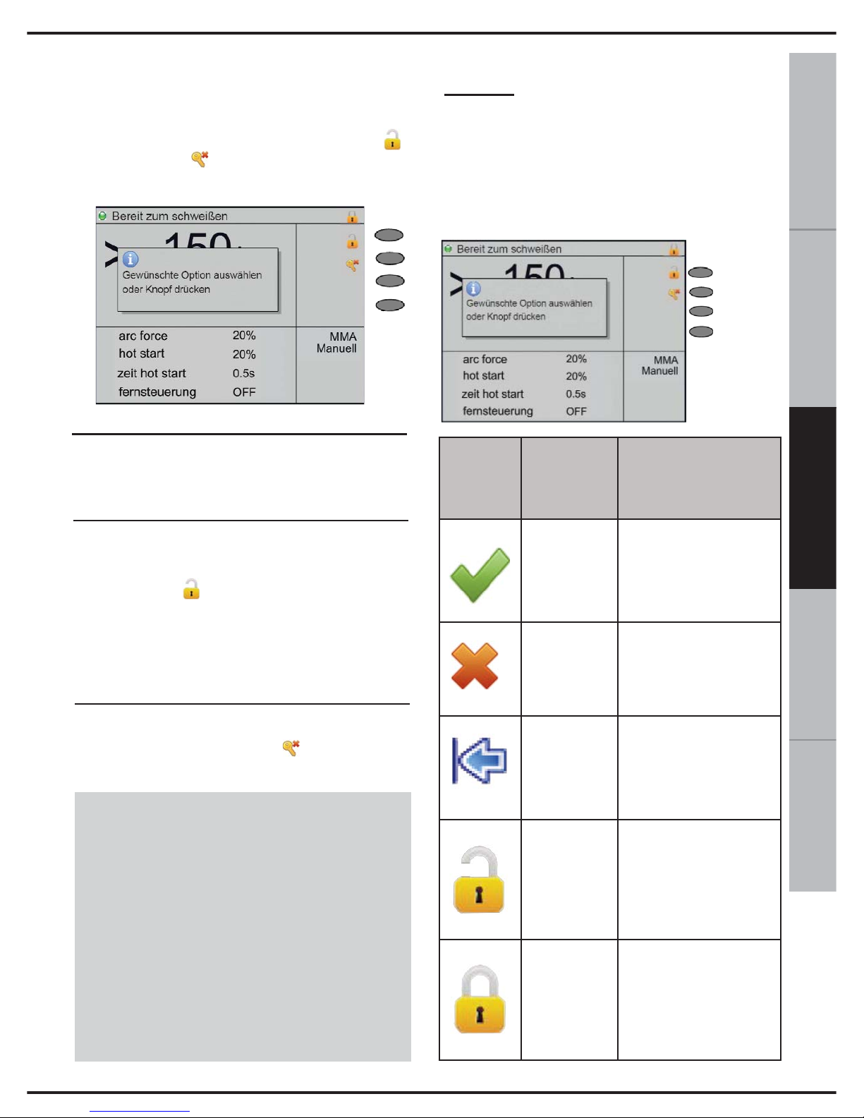
27
ESPAÑOL FRANÇAIS
DEUTSCH
ENGLISH
ITALIANO
3. Nach Bestätigung des Passworts zeigt das
Schweißgerät erneut die Anzeige unter Abb.
C an, den Schriftzug Gesperrt im Bereich 1
des Displays und das Etikett Freigeben
und Reset pw. (reset password) die den
Knöpfen 2 und 3 (Abb.1) im zweiten Bereich
des Displays zugeordnet wurden.
4. Um von der Funktion Sperren des
Schweißpunkts zurück zu kehren,
drücken Sie kurz Knopf 9 Abb. 1;
5. Sollten Sie den Schweißpunkt weiter
bearbeiten wollen, ist die Funktion
„Entsperren" zu aktivieren.
Dafür drücken Sie die Taste Funktion.
Die Funktion Freigabe wird das oben wie
oben beschrieben eingegebene Passwort
abfragen.
6. Die Funktion Reset Passwort wird
durch Drücken der Taste (Reset Pw)
aktiviert.
ACHTUNG:
Die Funktion Reset Passwort sollte dann
verwendet werden, wenn Sie sich nicht
mehr an das Passwort zum Sperren/
Entsperren erinnern.
Zur Anwendung dieser Funktion ist es
nötig, dass Sie direkt den technischen
Kundendienst FIMER kontaktieren.
Anhang:
Etiketten/ Ikons der Knöpfe/ Funktionstasten
und Info-Pop-ups
In der anschließenden Abbildung sowie in
der nachfolgenden Tabelle sind die
wichtigsten Etiketten /Ikone der Knöpfe/
Funktionstasten und Info-Pop-ups bzw.
Fehlermeldungen aufgelistet, die auf dem
Display erschienen können:
Fig.C
Key F1
Key F2
Key F3
Key F4
Symbol
Position
auf dem
Display
Beschreibung
Key F4
Wird eine Eingabe von
Daten seitens des Nutzers
benötigt, so gibt sie die Taste
an, die für die Bestätigung
zu drücken ist.
Key F3
Wird eine Eingabe von
Daten seitens des Nutzers
benötigt, so gibt sie die
Taste an, die zum Abbrechen zu drücken ist.
Key F1
Wird eine Eingabe von
Daten seitens des
Nutzers benötigt, so gibt
sie die Taste an, die für
das Löschen des letzten
Buchstabens zu drücken
ist.
Key F1
Wird über Knopf 10 (Abb.
1) die Funktion Tastatursperre aktiviert, gibt sie an,
welche Taste zum Entsperren zu drücken ist.
Key F1
Wird über Knopf 10 (Abb.
1) die Funktion
Tastatursperre aktiviert,
gibt sie an, welche Taste
zur Sperrung zu drücken
ist.
Page 96
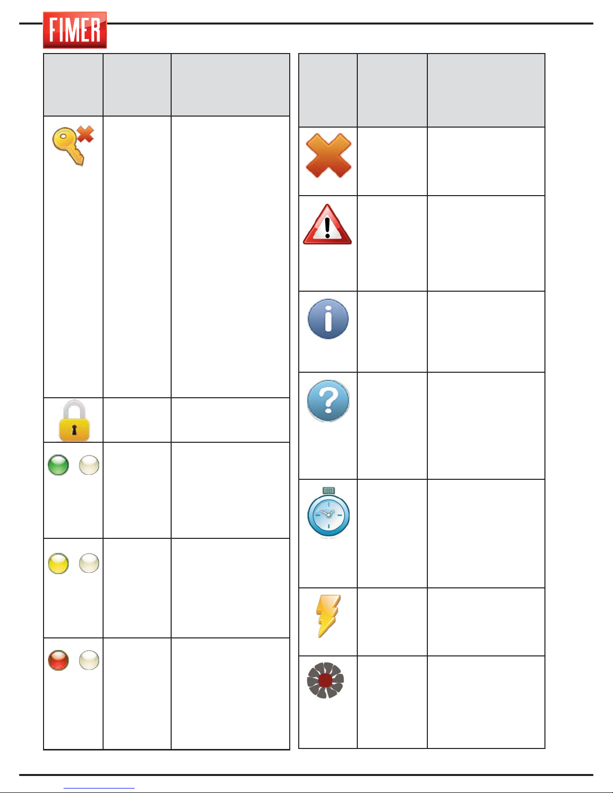
28
Symbol
Position
auf dem
Display
Beschreibung
Key F2
Wird über Knopf 9 (Abb. 1)
die Funktion Tastatursperre aktiviert, gibt sie an, welche Taste zu drücken ist,
um das vorher abgespeicherte Passwort zu löschen
(und gestattet so die Eingabe eines neuen Passworts). Neben der Funktion Löschen des Passworts
wird bei aktiver Tastensperre
die Tastatur wieder entsperrt.
ACHTUNG: Die Funktion
Reset Passwort sollte
dann verwendet werden,
wenn Sie sich nicht mehr
an das Passwort zum
Sperren/ Entsperren erinnern. Zur Anwendung dieser Funktion ist es nötig,
dass Sie direkt den technischen Kundendienst
FIMER kontaktieren.
(2)
Gibt an, dass die
Tastatursperre eingeschaltet ist.
(1)
Blinkt mit der Frequenz
1Hz und zeigt an, dass die
Anwendung aktiv ist.
Während des
Schweißvorgangs des
Geräts gibt es an, dass der
duty-cycle im Intervall eingeschlossen ist [60, 100]%.
(1)
Blinkt mit der Frequenz
1Hz und zeigt an, dass die
Anwendung aktiv ist.
Während des
Schweißvorgangs des
Geräts gibt es an, dass der
duty-cycle im Intervall eingeschlossen ist [35, 60]%.
(1)
Blinkt mit der Frequenz 1Hz
und zeigt an, dass die
Anwendung aktiv ist.
Während des
Schweißvorgangs des
Geräts gibt es an, dass der
duty-cycle im Intervall eingeschlossen ist [0, 35]%.
/
/
/
Symbol
Position
auf dem
Display
Beschreibung
POP UP
Die Pop-up Nachricht
gibt eine Fehlermeldung
an, die für das
Blockieren der
Gerätefunktion sorgt.
POP UP
Die Pop-up Nachricht gibt
eine Handlung an, die der
aktuelle Nutzer des
Geräts vollführt hat, die
Beachtung verlangt (z.B.
Einsetzen neuen Drahts
oder Reinigung
Gasdüse).
POP UP
Die Pop-up Nachricht ist
rein informativ (z.B.
Angabe der FirmwareVersionen /SD im Gerät).
POP UP
Die Pop-up Nachricht
verlangt die Eingabe von
Daten durch den Nutzer
(Z.B. Eingabe des
Programmnamens, des
Passwortes zum Sperren
oder Entsperren der
Tastatur).
(1)
Ersetzt die blinkende
LED-Anzeige bei Laden
eines Programms. Nach
vollständigem Laden des
Programms erlischt das
Symbol und es erscheint
erneut die blinkende
LED-Anzeige.
(2)
In Geräten mit HF-Karte
gibt es an, dass die Karte
für mehr als 0,5
Sekunden aktiv ist.
(2)
Gibt das Einschalten der
Kühlventilator in den
Geräten an, die vom
Programm einschaltbare
Ventilatoren besitzen.
Page 97
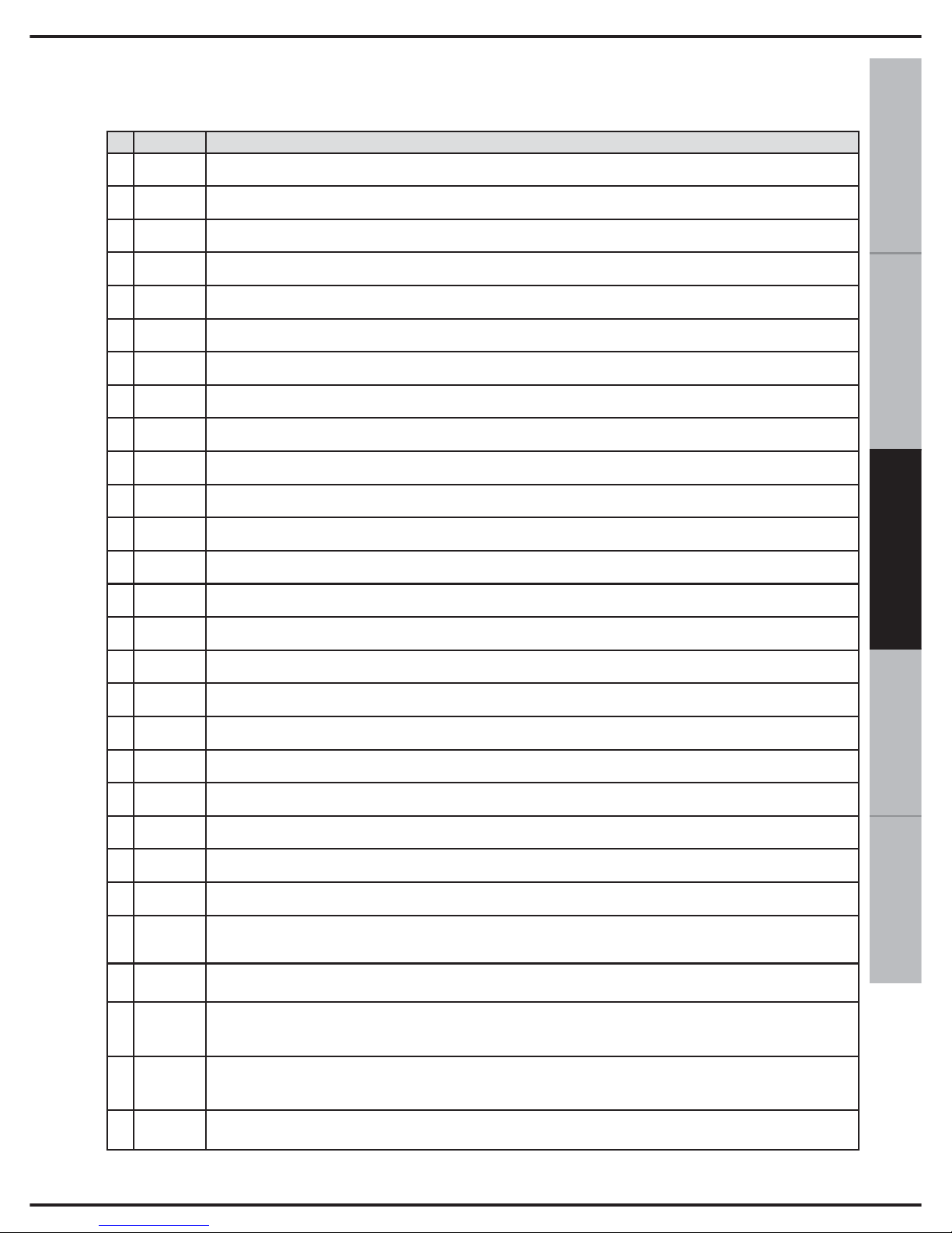
29
ESPAÑOL FRANÇAIS
DEUTSCH
ENGLISH
ITALIANO
E= error W= warning
23. ERROR CODE
Im Folgenden sind die Fehler, die auftreten können und ihre Beschreibungen:
Code
Beschreibung
E 8101 Ungültiger Pufferspeicher
E 8102 Fehler während der Dateneingabe
E 8103 Ungültiger CAN Index/Unterindex
E 8104 Objekt nur lesen
E 8105 Fehler während der Datenablese
E 8106 Zeitlimit wàhrend Dateneingabe erreicht
E 8107 Zeitlimit Datenablese erreicht
E 8108 MMS Applikationen nicht unterstützt
E 8109 Datenverbindung verloren
E 8201 Keine SD Card vorhanden
E 8202 SD card nicht formatiert
E 8203 Fehler während der Datenablese von Datei
E 8206 Datei nicht gefunden
E 8209 Synergetische Tabelle nicht verfügbar
E 820c Erfordertes Update SD Karte
E 8fa1 Menuerstellung unterbrochen
E 8fa2 Herarchische Menuerstellung unterbrochen
E 8fa3 Parametererstellung unterbrochen
E 8fb1 Falsche Konfiguration
W 4700
Manuelle Drahteingabe
Achtung, wenn die Feed-Taste gedrückt wird, erscheint
W 4701
Gasspülung
Achtung, wenn die Taste gedrückt wird Spülgas erscheint
E 9001
Inverter in Unterspannung
Warnung, wenn die Leistung der Maschine kurzgeschlossen ist, MMA oder WIG erscheint
E 9002
Inverter in Uberspannung
Achtung, wenn der Schutz Hardware Temperatur des Umrichters erscheint
E 9003
Energieversorgungsfehler
Achtung, wenn die Versorgungsspannung übersteigt die festgelegten Grenzen oder wenn es eine
oder mehrere Phasen (Drehstrom-Maschinen) erscheint
E 9004
Inverter überlastet
Warnung, wenn die Maschine übergeben wird das Tastverhältnis der Nutzungsbedingungen
E 9005
Geringer Wasserdruck
Signalisiert, dass angezeigt wird, wenn der Druck des Kühlmittels niedrig, wegen des Mangels an
der gleichen Flüssigkeit, die Anwesenheit von Luftblasen oder Luftblasen im Kühlkreislauf
E 9006
Ueberheizung AC Modul
Achtung, wenn die Schutz-Hardware Montage Temperatur Umpolung erscheint
E 9010
Torch Auslöser gedrückt, lassen Sie die Brennertaste und/oder korrekten Betrieb
Achtung, die beim Einschalten des Geräts erscheint, ist der Auslöser gedrückt
Page 98

30
ANZEICHEN
URSACHE/N
LÖSUNGEN/EMPFEHLUNGEN
Gerät schaltet sich aus
[Display: ausgeschaltet]
Keine Netzspannung vorhanden
Stellen Sie die Netzspannung
wieder her
24. FEHLERSUCHE
Nachfolgend werden die häufigsten Probleme aufgeführt, die sich ergeben können, sowie
die dazugehörige Lösung.
Netzwerkfehler
1) Ausfall einer Netzversorgung Phase
2) Netz-oder Unterspannung
1) Überprüfen Sie den Anschluss
an das Stromnetz und überprüfen
Sie, ob die Sicherungen intakt sind.
2) Sicherstellen, dass das Netz
einen Wert zwischen 360 und 440
V rms hat.
STÖRUNGEN BEIM SCHWEISSEN
[Display:Spannungsmangel
Wechselrichter]
Elektrodenkontakt mit der Masse
Elektrode von der Stück entfernen
Fehlende Zündung des
Lichtbogens
1) Es sind nicht beide Kabel
(Zangenhalter und Masse) angeschlossen
2) Die Kabel sind unterbrochen
3) Schlechter Kontakt zwischen
Massezange und Werkstück
4) Schlechter Kontakt zwischen Zange
und Elektrode
5) Falsche Einstellung der Schweißparameter
6) Schweißgerät gibt keinen Strom ab
1) Anschlüsse überprüfen
2) Kabel überprüfen
3) Anschlüsse überprüfen
4) Anschlüsse überprüfen
5) Eingestellte Parameter überprüfen
6) Schweißgerät überprüfen
Poröse Schweißnaht
Falscher Abstand und/oder falscher
Winkel des Handstücks
Der Abstand zwischen Elektrode und Werkstück muss gleich
dem Durchmesser des Kernstabs
der Elektrode selbst sein, bei
basischen Elektroden gilt L=Durchm. x 0,5, die Neigung darf nicht
übermäßig sein.
Vorliegen von Wasserstoff wegen Feuchtigkeit in der Ummantelung der Elektroden, falsche Aufbewahrung derselben
Elektroden ersetzen, Elektroden
nach Anweisungen des Herstellers/der Lieferfirma aufbewahren
korrekten Abstand zwischen Elektrode und Werkstück beibehalten
Schweißbogen zu lang
korrekten Abstand zwischen Elektrode und Werkstück beibehalten
Fehlende Schmelzung
1) falsche Stromparameter
2) zu hohe Schweißgeschwindigkeit
3) falsche Vorbereitung der Schweißflanken
4) falsche Schweißposition
1) korrekte Parameter verwenden, Geschwindigkeit vermindern
2) korrekte Schweißposition beibehalten
3) Schweißfuge korrekt vorbereiten
(Fugenwinkel öffnen)
4) Schweißposition korrigieren
Randkerben
1) zu hohe Stromparameter
2) falsche Schweißposition
3) übermäßige Schweißgeschwindigkeit
1) Stromparameter vermindern
2) Schweißposition korrigieren
3) Schweißgeschwindigkeit
vermindern
Page 99
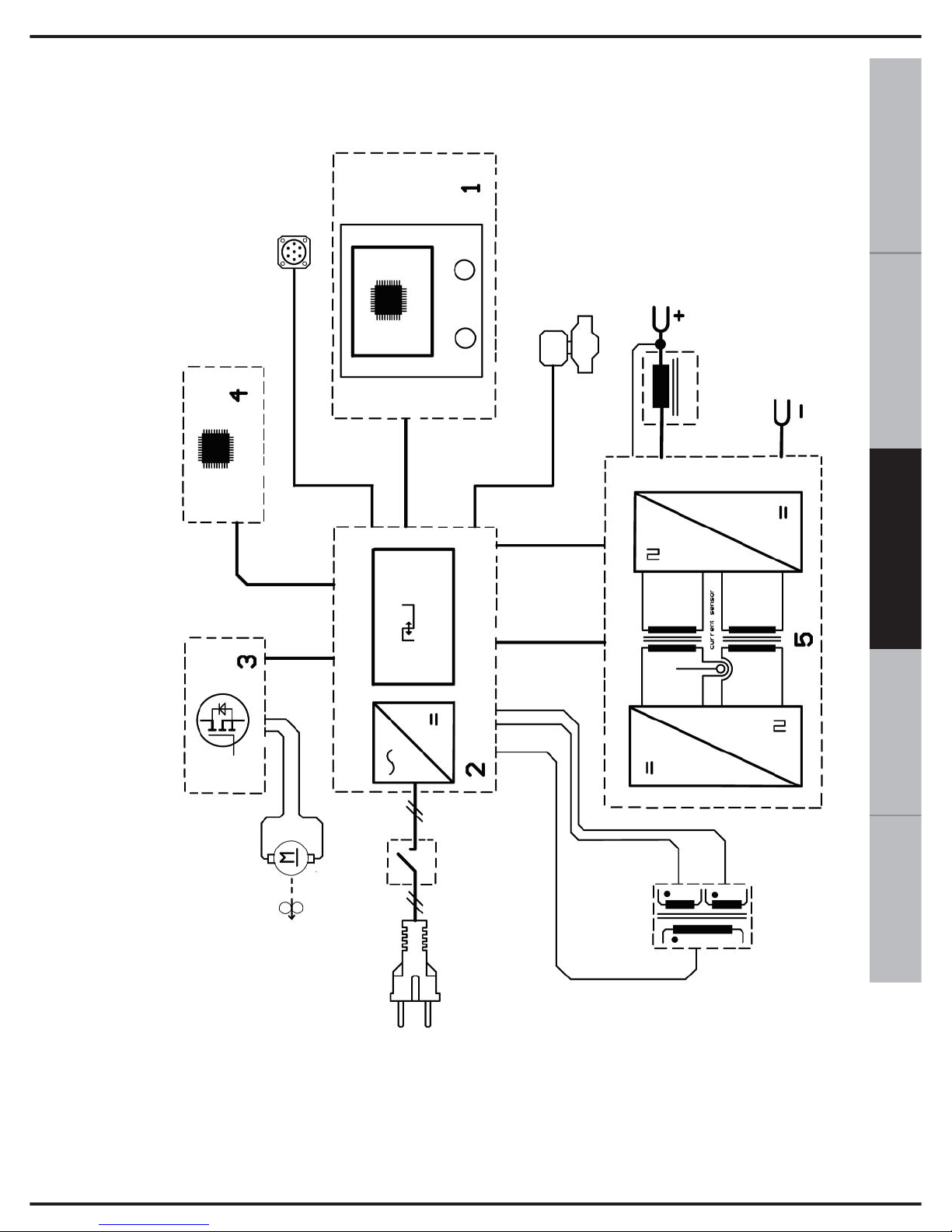
31
ESPAÑOL FRANÇAIS
DEUTSCH
ENGLISH
ITALIANO
25. BLOCKSCHALDBILD
1. Kontrol-Panel
2. Leistungskontrollkarte
3. Motorsteuerung
4. Bedienfeld Schweißprozess
5. Wechselrichter
6. Eigenbedarfstransformator
Page 100
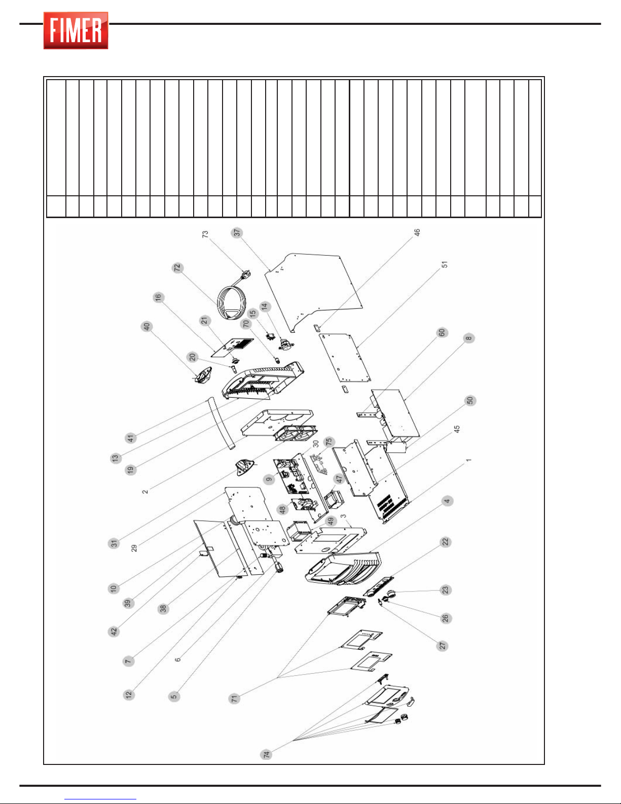
32
26. ERSATZTEILE
4
Oberer Teil der
Kunstoff-Frontplatte
5
Euro Stecker Kit
7
Kabelzuleitung
8
Leistungskontrollkarte
9
Kontrollkarte
10
Spulenbefestigung
12
Scharnier
13
Oberes Hinter-Plastikteil
14
20A Wellenschalter
15
Elektroventil
16
Hinteres Paneel
19
Untere Schale
20
Sicherungshalter
21
5-poliger Stecker
22
Leistungspanel
23
Dinse
26
7-poliger Stecker
27
Gas-Anschluss
31
Ventilator
37
Haube
38
Feste linke Wand
39
Bewegliche Wand
40
Klinkhalter
41
Klinke
42
Gleitverschluss
47
Induktanz
48
Motor-Kontrollkarte
49
Hilfstransformer
50
Leistungs-Förderanlage
60
Lexan Platte für die
Befestigung der Kühlkörper
70
Schnelle Kupplung
71
Display Kit
72
Leitungskabel
74
Frontrahmen Kit
 Loading...