

Page 1
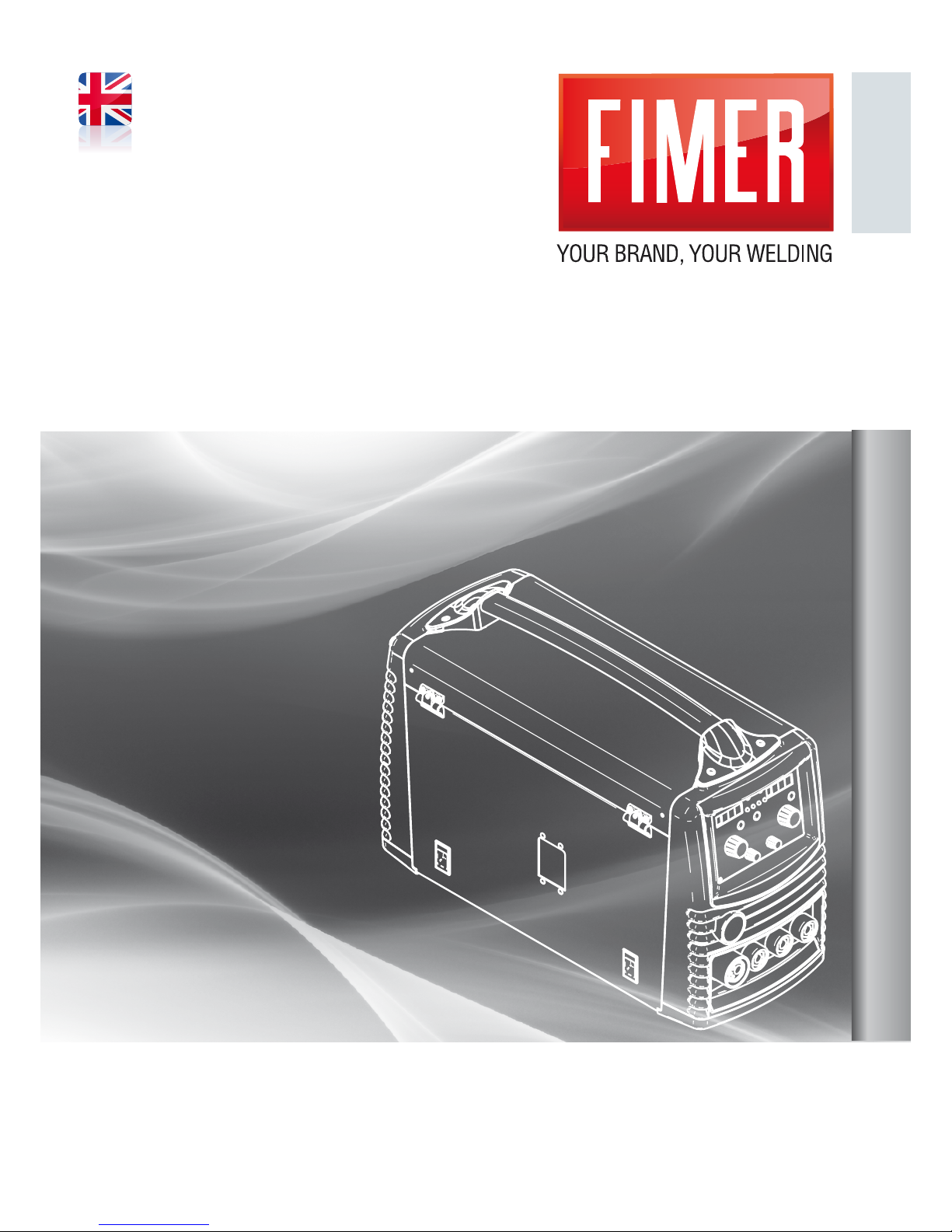
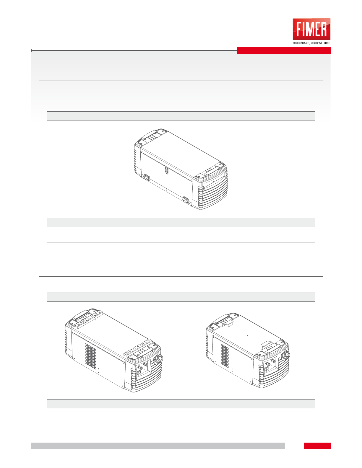
SYMPLEX 320
SYMPLEX 420
Ed. 2014_11_11
INSTRUCTION MANUAL
910.100.512GB REV00
Page 2
Original instructions
BEFORE USING THIS EQUIPMENT IT IS RECOMMENDED TO READ THIS INSTRUCTION
MANUAL!
IN CASE OF MISSING READING, CASES OF FAILURE AND/OR DANGERS FOR THE USER
COULD HAPPEN!
THE UNIT CAN ONLY BE USED BY PEOPLE WHO PERFECTLY KNOW THE SPECIFIC
SECURITY RULES!
This manual is an integrant part of the equipment and it must be attached in every displacement or resale.
It is user’s responsibility to keep it intact and in good conditions.
The manufacturer has the right to apply modies in every moment or without any forewarning.
Every Fimer product is minded, designed and produced in Italy in our sites.
This is guarantee of high quality and reliability.
Translation, production and adaptation rights, total or partial and with every mean (photostatic copies, lm
and microlm included) are reserved and banned without the written authorization of the manufacturer.
DEGREE OF ‘WORK ENVIRONMENT POLLUTION: CLASS 3
Page 3
Dear Customer,
by thanking for Your choice, Fimer welcomes you.
Fimer products are characterized by a modern inverter technology, an innovation of process and
extreme simplicity of use. All to guarantee a sure result and efcient guardianship of the user.
At the end of the productive process, every equipment is tested in our laboratory by making a rst
welding/cutting. The continuous r&d devoted to improve the technology and the optimization of the
process have pushed us on top of the market.
Our production, assistance and training site is exclusively on Italian region and we can praise a
100% MADE IN ITALY. In addition, Fimer has inside a complete chain thanks to an efcient and high
quality carpentry department, lines of electronic boards and testing/assembly department which make
possible to create the entire product.
To be able to reach the best welding processes and guarantee a reliable and long lasting use of the
equipment, it is very important to observe our indications included in the present manual.
Hoping our product satisfy all Your expectations, we thank You for the given trust.
Best regards,
Filippo Carzaniga
Managing Director
Page 4
APPLICATIONS
STANDARD MIG/MAG WELDING
Arc welding by using a wired electrode where both arc and welding pool are protected from atmosphere
thanks to a shielding gas protection provided by an external source.
FLUX CORED WIRE MIG/MAG WELDING
Welding by ux cored wires is about a metallic coating and a soul made of powders. As per standard MIG/
MAG welding, the arc is protected from atmosphere by a shielding gas.
NO-GAS FLUX CORED WIRE MIG/MAG WELDING
Welding by ux cored wires is about a metallic coating and a core made of powders. Otherwise of standard
MIG/MAG welding, the arc is self protected from the powders contained in the core and it is always used a
continuous current with direct polarity (torch connected to negative pole “-“).
ELECTRODE/MMA MANUAL WELDING
MMA welding uses the electric arc generated between consumable electrode and fusion pool. It doesn’t use
any protection gas, in fact the atmosphere protection comes from the electrode.
GOUGING
The gouging uses the arc creation between a consumable electrode made by carbon/graphite and liquid
fusion pool which is expelled by a jet of compressed air; usually used to remove welding; pay attention to
special torches use.
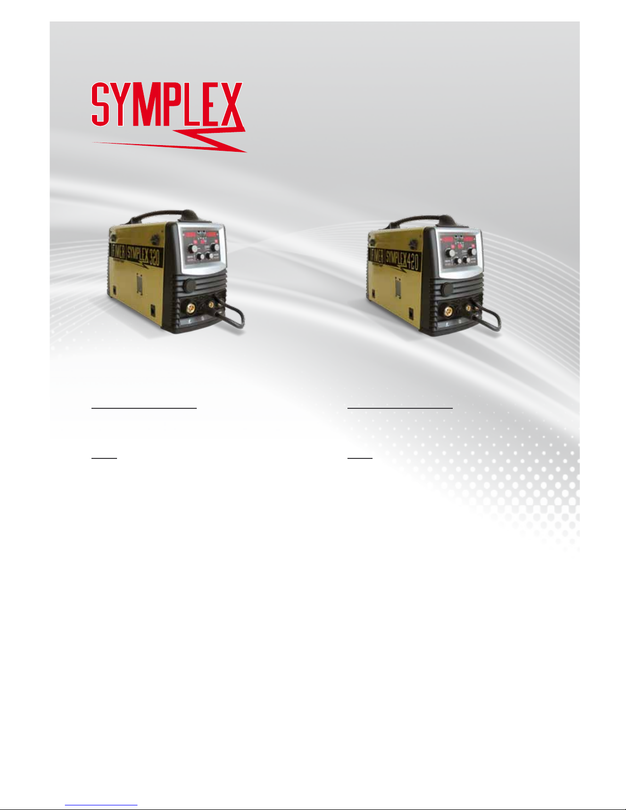
SYMPLEX 320
5T5.321.152
MIG-MAG / MMA 3PH
15 - 320 A (MIG-MAG)
15 - 300 A (MMA)
Peso
19.8 kg
SYMPLEX 420
5T5.421.152
MIG-MAG / MMA 3PH
15 - 400 A (MIG-MAG)
15 - 370 A (MMA)
Peso
21.3 kg
Page 5
SYMPLEX 320
SYMPLEX 420
Page 6

6
SUMMARY
WARNING _________________________________________________________________________________ 7
DEVICE DESCRIPTION _____________________________________________________________________ 10
2.1 SYMPLEX (MODELS 320-420) FRONT VIEW .......................................................................................................................... 10
2.2 SYMPLEX (MODELS 320-420) REAR VIEW..............................................................................................................................11
INTERFACE PANEL ________________________________________________________________________ 12
3.1 CONTROL PANEL DIAGRAM .................................................................................................................................................. 12
3.2 CONTROL PANEL DESCRIPTION ........................................................................................................................................... 13
FUNCTIONING ____________________________________________________________________________ 15
4.1 EQUIPMENT COOLING ........................................................................................................................................................... 15
4.2 EARTH CABLE ......................................................................................................................................................................... 15
4.3 ELECTRICITY CONNECTION .................................................................................................................................................. 15
4.4 SHIELDING GAS SUPPLY ........................................................................................................................................................ 16
4.5 SHIELDING GAS QUANTITY REGULATION ............................................................................................................................ 16
4.6 MIG/MAG WELDING SHIELDING GAS SETTING ................................................................................................................... 16
MIG-MAG WELDING _______________________________________________________________________ 17
5.1 TORCH PREPARATION ........................................................................................................................................................... 17
5.2 TORCH AND EARTH CABLE INSTALLATION ......................................................................................................................... 18
5.3 WIRE SPOOL HOUSING.......................................................................................................................................................... 18
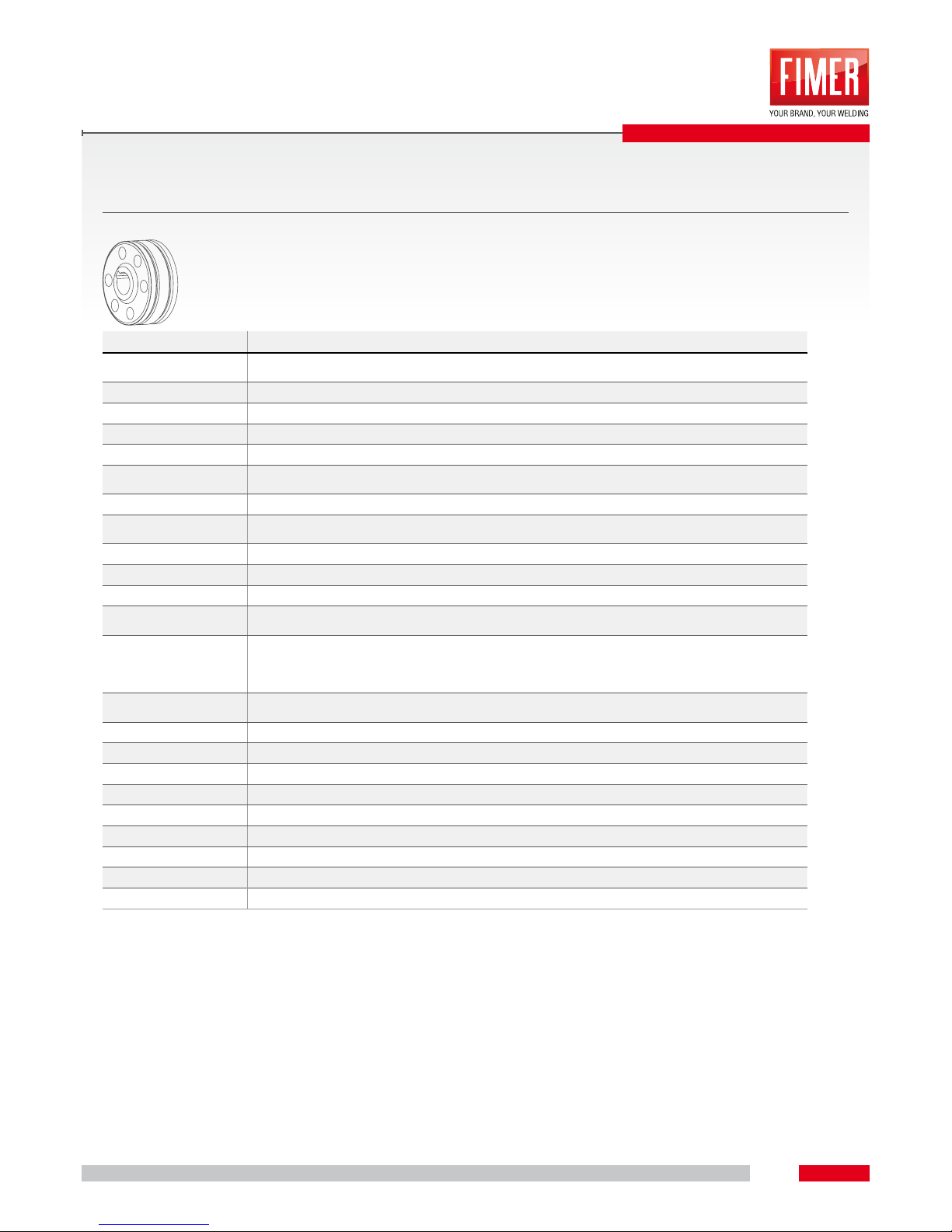
5.4 ROLLS REPLACEMENT ........................................................................................................................................................... 20
5.5 FUNCTION 2T .......................................................................................................................................................................... 21
5.6 FUNCTION 4T .......................................................................................................................................................................... 22
MMA WELDING ___________________________________________________________________________ 23
6.1 CONNECTING THE ELECTRODE HOLDER AND THE EARTH CABLE ................................................................................. 23
6.2 WELDING CURRENT MANUAL SELECTION .......................................................................................................................... 23
6.3 ARC FORCE ............................................................................................................................................................................. 23
6.4 HOT START .............................................................................................................................................................................. 23
6.5 ANTISTICKING ......................................................................................................................................................................... 23
ALARMS/TROUBLESHOOTING ______________________________________________________________ 24
7.1 ERROR MESSAGES ................................................................................................................................................................ 24
CARE AND MAINTENANCE _________________________________________________________________ 26
8.1 DAILY MAINTENANCE ............................................................................................................................................................. 26
8.2 MONTHLY MAINTENANCE ...................................................................................................................................................... 26
8.3 REPAIRS ................................................................................................................................................................................... 26
SERVICE MENU ___________________________________________________________________________ 27
9.1 SERVICE MENU ....................................................................................................................................................................... 27
9.2 ENTERING IN SERVICE MENU ............................................................................................................................................... 27
9.3 NAVIGATE IN SERVICE MENU ................................................................................................................................................ 27
9.4 MENU LEGENDA ..................................................................................................................................................................... 27
9.5 MENU SERVICE EXIT .............................................................................................................................................................. 28
9.6 WATER COOLING UNIT SERVICE MENU ............................................................................................................................... 28
ACESSORIES _____________________________________________________________________________ 29
10.1 TROLLEY ................................................................................................................................................................................ 29
10.2 TOOLSBOX ............................................................................................................................................................................ 30
10.3 WATER COOLING UNIT (WCS1 - WCS2) ............................................................................................................................. 30
10.4 ACCESSORIES ...................................................................................................................................................................... 31
NOTE ____________________________________________________________________________________ 32
DISPOSAL _______________________________________________________________________________ 35
12.5 DISPOSAL .............................................................................................................................................................................. 35
Page 7
7
1
WARNING
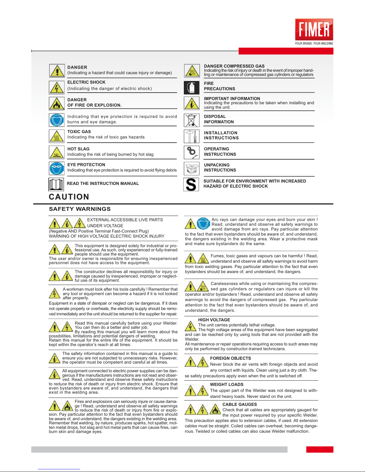
WARNING SYMBOLS
WARNING SYMBOLS
CAUTION
CAUTION
DANGER
(Indicating a hazard that could cause injury or damage)
DANGER
OF FIRE OR EXPLOSION.
Indicating that eye protection is required to avoid
burns and eye damage.
TOXIC GAS
Indicating the risk of toxic gas hazards
HOT SLAG
Indicating the risk of being burned by hot slag
EYE PROTECTION
Indicating that eye protection is required to avoid flying debris
ELECTRIC SHOCK
(Indicating the danger of electric shock)
DANGER COMPRESSED GAS
Indicating the risk of injury or death in the event of improper hand-
ling or maintenance of compressed gas cylinders or regulators
IMPORTANT INFORMATION
Indicating the precautions to be taken when installing and
using the unit.
DISPOSAL
INFORMATION
FIRE
PRECAUTIONS
SAFETY WARNINGS
This equipment is designed solely for industrial or pro-
fessional use. As such, only experienced or fully-trained
people should use the equipment.
The user and/or owner is responsible for ensuring inexperienced
personnel does not have access to the equipment.
EXTERNAL ACCESSIBLE LIVE PARTS
UNDER VOLTAGE
(Negative AND Positive Terminal Fast-Connect Plug)
WARNING OF HIGH VOLTAGE ELECTRIC SHOCK INJURY
The safety information contained in this manual is a guide to
ensure you are not subjected to unnecessary risks. However,
the operator must be competent and careful at all times.
The constructor declines all responsibility for injury or
damage caused by inexperienced, improper or neglect-
ful use of its equipment.
A workman must look after his tools carefully ! Remember that
any tool or equipment can become a hazard if it is not looked
after properly.
Equipment in a state of disrepair or neglect can be dangerous. If it does
not operate properly or overheats, the electricity supply should be remo-
ved immediately and the unit should be returned to the supplier for repair.
All equipment connected to electric power supplies can be dan-
gerous if the manufacturers instructions are not read and obser-
ved. Read, understand and observe these safety instructions
to reduce the risk of death or injury from electric shock. Ensure that
even bystanders are aware of, and understand, the dangers that
exist in the welding area.
Read this manual carefully before using your Welder.
You can then do a better and safer job.
By reading this manual you will learn more about the
possibilities, limitations and potential dangers of welding.
Retain this manual for the entire life of the equipment. It should be
kept within the operator’s reach at all times.
Fires and explosions can seriously injure or cause dama-
ge ! Read, understand and observe all safety warnings
to reduce the risk of death or injury from fire or explo-
sion. Pay particular attention to the fact that even bystanders should
be aware of, and understand, the dangers existing in the welding area.
Remember that welding, by nature, produces sparks, hot spatter, mol-
ten metal drops, hot slag and hot metal parts that can cause fires, can
burn skin and damage eyes.
Fumes, toxic gases and vapours can be harmful ! Read,
understand and observe all safety warnings to avoid harm
from toxic welding gases. Pay particular attention to the fact that even
bystanders should be aware of, and understand, the dangers.
HIGH VOLTAGE
The unit carries potentially lethal voltage.
The high voltage areas of the equipment have been segregated
and can be reached only by using tools that are not provided with the
Welder.
All maintenance or repair operations requiring access to such areas may
only be performed by constructor-trained technicians.
FOREIGN OBJECTS
Never block the air vents with foreign objects and avoid
any contact with liquids. Clean using just a dry cloth. The-
se safety precautions apply even when the unit is switched off.
CABLE GAUGES
Check that all cables are appropriately gauged for
the input power required by your specific Welder.
This precaution applies also to extension cables, if used. All extension
cables must be straight. Coiled cables can overheat, becoming dange-
rous. Twisted or coiled cables can also cause Welder malfunction.
WEIGHT LOADS
The upper part of the Welder was not designed to with-
stand heavy loads. Never stand on the unit.
Carelessness while using or maintaining the compres-
sed gas cylinders or regulators can injure or kill the
operator and/or bystanders ! Read, understand and observe all safety
warnings to avoid the dangers of compressed gas. Pay particular
attention to the fact that even bystanders should be aware of, and
understand, the dangers.
Arc rays can damage your eyes and burn your skin !
Read, understand and observe all safety warnings to
avoid damage from arc rays. Pay particular attention
to the fact that even bystanders should be aware of, and understand,
the dangers existing in the welding area. Wear a protective mask
and make sure bystanders do the same.
INSTALLATION
INSTRUCTIONS
OPERATING
INSTRUCTIONS
UNPACKING
INSTRUCTIONS
READ THE INSTRUCTION MANUAL
SUITABLE FOR ENVIRONMENT WITH INCREASED
HAZARD OF ELECTRIC SHOCK
Page 8
8
1
WARNING
WELDING OPERATION
WELDING OPERATION
SAFETY INSTRUCTIONS
SAFETY INSTRUCTIONS
PERSONNEL PROTECTION
PERSONNEL PROTECTION
LOCATION
Place the Welder well away from heat sources. Place the
Welder in a well-ventilated environment. Place the Welder in
a safe, protected area. It must not be installed outdoors. Do not install the
Welder in dusty environments. Dust can get into the inner parts of the unit
and inhibit cooling. The Welder must be positioned on a flat, stable surfa-
ce that extends further than the units own dimensions in all directions.
CLEAN LOCATIONS
The installation area must be kept clean and dry to be sure the Welder
fans do not draw in small objects or liquids. Not only could the equip-
ment malfunction but a serious risk of fire outbreak could be created.
REPAIRS
Never attempt to repair the Welder yourself. Always
refer to the manufacturer or an authorized repairer.
All warranty provisions will immediately become null and void if any repair,
or attempt to repair, not specifically authorized in writing or handled by
the constructor is carried out. Furthermore, the constructor will accept
no responsibility for any malfunction or damage resulting as a conse-
quence of such unauthorized action.
SPARE PARTS
Use only manufacturer-recommended spare parts.
Other spare parts could cause equipment mal-
function. The use of non-original spare parts will also result in the war-
ranty provisions becoming null and void, releasing the manufacturer
from any responsibility for malfunction or damage resulting as a con-
sequence of such action.
CAUTION !
Welding processes can be dangerous for the operator and bystanders
if the safety warnings and instructions are not heeded.
WORK-AREA FLOORING
The work-area flooring MUST be fireproof.
WORK-AREA SURFACES
Work benches or tables used during welding
MUST have fireproof surfaces.
PROTECTION MASK
Wear a protective non-flammable welding mask
to protect your neck, your face and the sides of
your head. Keep the front lens clean and replace it if it is broken
or cracked. Place a transparent protection glass between the mask
and the welding area.
CLOTHING
Wear close-fitting, closed, non-flammable, pocke-
tless clothing.
EXTINGUISHER
Always place an approved fire extinguisher in the immediate vicinity
of the work area. Fire extinguishers should be checked regularly.
EYE PROTECTION
NEVER look at the arc without appropriate eye protection.
FUMES AND GASES 1
Clean away paint, rust or any other dirt from the item to
be welded to avoid the creation of dangerous fumes.
FUMES AND GASES 2
NEVER weld on metals containing zinc, mercury, chro-
mium, graphite, heavy metals, cadmium or beryllium unless
the operator and the bystanders use appropriate air-supplied respirators.
CONFINED SPACES
When welding in small environments, leave the power
source outside the area where welding will take place and
attach the grounding clamp to the part to be welded.
HUMIDITY
Never weld in wet or humid environments.
DAMAGED CABLES
Never use damaged cables. (This applies to both
the power and the welding cables.)
DAMAGED CABLES
Never remove the unit side panels. If the side panels
can be opened, always checked they are closed
tightly before starting any work.
HIGH VOLTAGE PROTECTION
HIGH VOLTAGE PROTECTION
Together with the previous instructions, the following pre-
cautions should be strictly observed
FIRE PREVENTION
FIRE PREVENTION
Together with the previous instructions, the following pre-
cautions should be strictly observed.
Welding operations require high temperatures therefore
the risk of fire is great.
TECHNICAL ASSISTANCE
The Welder must be taken to an authorized Technical Assi-
stance Centre if the equipment has been damaged in any way
or if any one of the following events occurs : liquid infiltration; dama-
ge caused by falling objects; exposure to rain or humidity (exceeding
the specified limits); malfunction; performance failure or if the equip-
ment has been dropped.
OVERLOAD PROTECTION
Check that the power source supplying the Welder carries the
correct voltage and is safety-protected. The power switch must open all the
power supply circuits. (If a single-phase connection is used, both the live and
the neutral poles must be open. If a three-wire connection is used , all three
poles must be open. Four-wire circuits require all poles and neutral open).
Time-delayed fuses or K-standard circuit breakers should be used.
CABLE COLOURS
The green-yellow wire is for earthing. (Don’t use it for
anything else !)
INSTALLATION ENVIRONMENT
The equipment is not suitable for use in washrooms,
shower cubicles, pool areas or similar environments. If
you are obliged to use the unit in such areas, turn off all water sup-
plies and check the area has been evacuated.
OPERATING AND/OR INSTALLATION ENVIRONMENT 3
Never use the Welder in an explosive, corrosive, abra-
sive or saline environment.
VENTILATION
Weld in a well-ventilated environment that does not have
direct access to other work areas.
EARTHING
If the Welder was not already supplied with a plug, connect the
earth wire first. When removing the plug, disconnect the earth
wire last.
PLUG AND POWER SUPPLY
If the Welder already has a plug attached, check that it is appro-
priate for the wall-socket you intend using. Never tamper with
the power cable.
RELOCATION 1
Some Welders are extremely heavy therefore care should be
taken when relocating the unit. Check the floor or platform wei-
ght load limitations before relocating the unit if the Welder is to be used,
even only temporarily, in a non-industrial environment
OPERATING AND/OR INSTALLATION ENVIRONMENT 1
The Welder was not designed for installation or use in areas where it
could be subject to blows or vibration, such as road-vehicles, railway
carriages, cable-cars, aircraft, ships or boats or similar environments (including
cranes, conveyor-carriers or any other mobile equipment prone to vibration)
OPERATING AND/OR INSTALLATION ENVIRONMENT 2
The Welder should never be used or stored in the rain or in snow.
RELOCATION 2
Never store or move the Welder in an inclined position or on its
side.
Together with the previous instructions, the following
precautions should be strictly observed
Page 9
9
1
WARNING
CLEAN ENVIRONMENT
Remove all flammable materials away from
the work environment.
SERIOUS DANGER ! 1
NEVER weld in confined spaces (e.g. in a con-
tainer vehicle, a cistern or a storeroom etc.) where toxic, inflamma-
ble or explosive materials are, or have been, located or stored.
Cisterns, in particular, may still contain toxic, flammable or explosi-
ve gases and vapours years after they have been emptied.
SERIOUS DANGER! 3
NEVER use the Welder to melt frozen water
pipes.
SERIOUS DANGER ! 2
NEVER weld a cistern that contains (or has stored)
toxic, inflammable or explosive materials. They could
still contain toxic, flammable or explosive gases and vapours years
after they have been emptied. If you are obliged to weld a cistern,
ALWAYS passivate it by filling it with sand or a similar inert sub-
stance before starting any work.
WELDING ENVIRONMENT VENTILATION
Ventilate the welding environment carefully. Maintain
sufficient air-flow to avoid toxic or explosive gas accumulation.
Welding processes on certain kinds or combinations of metals can
generate toxic fumes. In the event of this happening, use air-sup-
ply respirators. BEFORE welding, read and understand the wel-
ding alloy safety provisions.
GAS TYPES
These welders use only inert (non-flammable) gases for welding
arc protection. It is important that the appropriate type of gas is
chosen for the type of welding being performed.
UNIDENTIFIED GAS CYLINDERS
NEVER use unidentified gas cylinders.
PRESSURE REGULATOR 1
NEVER connect the cylinder directly to the Welder.
Always use a pressure regulator.
PRESSURE REGULATOR 2
Check the regulator is performing its function properly.
Read the regulator instructions carefully.
PRESSURE REGULATOR 3
Never lubricate any part of the regulator.
PRESSURE REGULATOR 4
All regulators are designed for a specific type of gas.
Check the regulator is appropriate for the protective
gas to be used.
VENTILATION
VENTILATION
Together with the previous instructions, the following pre-
cautions should be strictly observed
PROTECTIVE WELDING GASES
PROTECTIVE WELDING GASES
Together with the previous instructions, the following
precautions should be strictly observed when welding
with protective gases
WALL AND FLOOR PROTECTION
The walls and flooring surrounding the welding
environment must be shielded using non-flammable materials. This
not only reduces the risk of fire but also avoids damage to the wal-
ls and floors during welding processes.
EXTINGUISHER
Place an approved and appropriately-sized fire extinguisher in
the work environment.
Check its working order regularly (carry out scheduled inspections)
and ensure that all parties involved know how to use one.
DAMAGED GAS CYLINDERS
NEVER use damaged or faulty cylinders.
CYLINDER RELOCATION
NEVER lift a gas cylinder by holding the regulator.
GAS CYLINDERS
Do not expose gas cylinders to excessive heat sour-
ces, sparks, hot slag or flames.
GAS HOSE 1
Check the gas hose is not damaged.
GAS HOSE 2
Always keep the gas hose well away from the work
area.
ELECTRIC SHOCK
Together with the previous instructions, the following pre-
cautions should be strictly observed to reduce the risk of
electric shock
ELECTRIC SHOCK INJURY
DO NOT touch a person suffering from electric shock if
he/she is still in contact with the cables. Switch the mains
power source off immediately THEN provide assistance.
CABLE CONTACT
Do not tamper with power cables if the mains power is still
switched on. Do not touch the welding circuitry. Welding cir-
cuitry is usually low voltage, however, as a precaution, do not tou-
ch the welder electrodes.
CABLE AND PLUG PRECAUTIONS
Check the power supply cable, plug and wall-socket regularly.
This is particularly important if the equipment is relocated often.
REPAIRS
Never attempt to repair the Welder yourself. The result would
not only cause warranty cancellation but also high danger risks.
MAINTENANCE PRECAUTIONS
Always check that the electric power supply has been discon-
nected before performing any of the maintenance opera-
tions listed in this manual ( e.g. before replacing any of the fol-
lowing: worn electrodes, welding wires, the wire feeder etc.)
Never point the welding gun or the electrode towards yourself
or others.
Check no power supply cables, telephone cables or other
electrical items (e.g. computer cables, control lines etc.) are
in the vicinity of the Welder.
Check there are no telephones, televisions, computers or other
transmission devices close to the Welder.
ELECTROMAGNETIC COMPATIBILITY
Make sure that people with pace-makers are not in the imme-
diate vicinity of the Welder.
Do not use the Welder in hospitals or medical environments
(including veterinary surgeries). Make especially sure there is
no electrical medical equipment being used close to where wel-
ding is being done.
Should the Welder interfere with other apparatus, take the fol-
lowing precautionary measures:
1. Check the Welder’s side panels are securely fastened.
2.Shorten the power supply cables.
Place EMC filters between the Welder and the power source.
EMC compatibility : CISPR 11, Group 2, Class A.
This Class A equipment is not intended for use in residential
locations where the electrical power is provided by the public
low-voltage supply system. There may be potential difficulties
in ensuring electromagnetic compatibility in those locations, due to
conducted as well as radiated disturbances.
This equipment does not comply with IEC 61000-3-12. If it is
connected to a public low voltage system, it is the responsabi-
lity of the installer or user of the equipment to ensure, by consultation
with the distribution network operator if necessary, that the equipment
may be connected.
This equipment is suitable for using in industrial environments
with mains power protected by residual current operated cir-
cuit-breaker (time delay), Type B and tripping current of >200 mA
Page 10
10
2
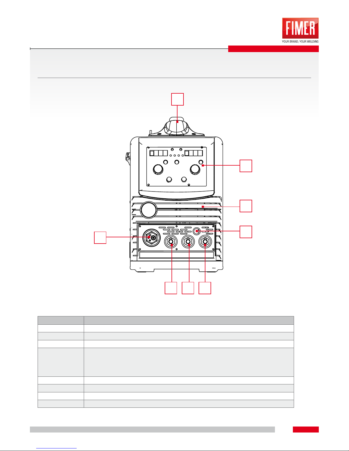
2.1 SYMPLEX (models 320-420) FRONT VIEW
REFERENCE DESCRIPTION
1 TRANSPORT HANDLE
2 CONTROL PANEL/INTERFACE
3 MIG/MAG CENTRAL CONNECTION FOR TORCH (EURO)
4 WELDING CURRENT CABLE FOR EURO CONNECTION POLARITY:
• MIG/MAG = PLUG IN “ + “
• SELF SHIELDED WIRE = PLUG IN “ - “
• MMA = PLUG IN “ 0 “
5 WELDING SOCKET CURRENT“ - “
6 WELDING SOCKET CURRENT “ +“
7 NO CURRENT SOCKET “ 0 “ , PLUG IN ONLY FOR MMA WELDING
8 COOLING AIR OUTLET
DEVICE DESCRIPTION
4
567
3
2
1
8
Page 11
DEVICE DESCRIPTION
11
2
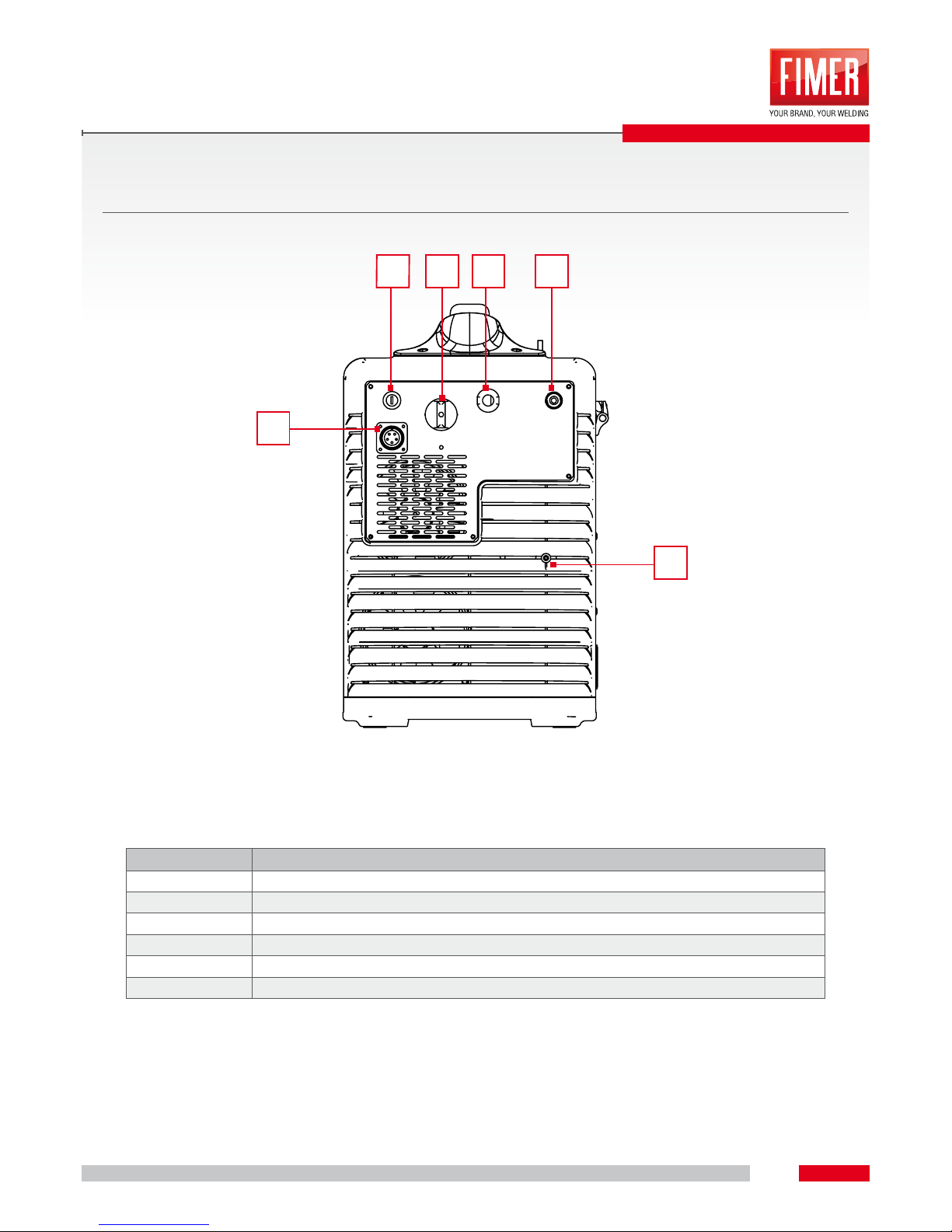
2.2 SYMPLEX (models 320-420) REAR VIEW
REFERENCE DESCRIPTION
1 SAFETY FUSE FOR WATER COOLING UNIT 4A - T 500V
2 5 POLE SOCKET FOR SUPPLY/SIGNALS WATER COOLING UNIT
3 MAIN SWITCH, MACHINE ON/OFF
4 MAINS CABLE
5 SHIELDING GAS QUICK COUPLING (MIG/MAG)
6 COOLING AIR OUTLET
2
31
6
4 5
Page 12
12
3
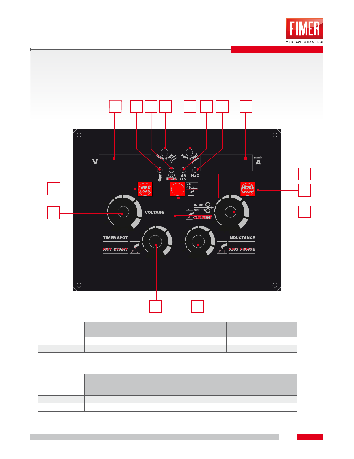
3.1 CONTROL PANEL DIAGRAM
Following all the information about control panel model Symplex 320 – Simplex 420
Wire speed
(m/min)
Welding
voltage (V)
Soft Start
(m/min)
Burn Back
Time (ms)
Tacking
time (s)
Inductance
min 1,5 10 1 30 0 -40
max 22 35 5 120 20 40
Chart 1: parameters Simplex320 – Simplex420 in MIG
Simplex320
welding current (A)
Simplex420
welding current (A)
Simplex 320 - 420
Hot Start (%) Arc Force (%)
min 15 15 100 100
max 300 370 200 200
Chart 2: parameters Simplex320 – Simplex420 in MMA
INTERFACE PANEL
3
6
1
7
5
4
98
101312 14 15 211
PU3 PU1 PU2
EN1
DL3DL2
T2 T1
DL1DL17
EN2
POT4 POT3
Page 13
INTERFACE PANEL
13
3
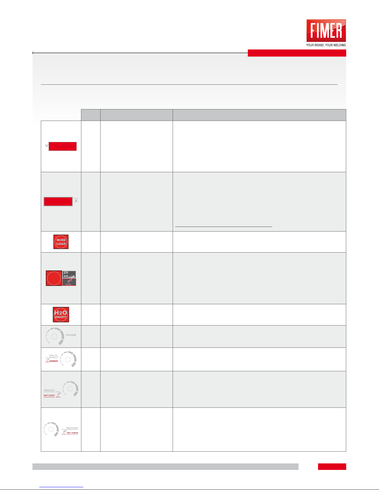
3.2 CONTROL PANEL DESCRIPTION
POS. DESCRIPTION FUNCTION
1 VIEW DISPLAY LEFT
It shows the welding voltage set while during welding process visualizes
the voltage measured by the machine.
It’s also showed, when modied, the tacking time set.
On MMA mode it shows the welding voltage measured by the machine.
It’s also showed, when modied, the reference parameter of the “Hot
Start” percentage.
2 VIEW DISPLAY RIGHT
It shows the wire speed set while during welding process visualizes the
current measured by the machine.
It’s also showed, when modied, the inductance parameter.
On MMA mode it shows the reference current set while during welding
process visualizes the current measured by the machine. It’s also showed,
when modied, the reference parameter of the “Arc Force” percentage.
Both displays contribute to errors viewing.
3
(PU3)
WIRE LOADING BUTTON
It allows the manual wire loading at the speed set before welding process,
on the display appears “WIRE LOAD”.
4
(PU1)
2S/4S/MMA
COMMUTATION BUTTON
On MIG mode it allows to set the functioning in 2 or 4 strokes. During
2 strokes mode (2s) the machine welds for all the time long when torch
button is pushed.
During 4 strokes mode (4s) a rst pressure on torch button at start, the
second pressure to stop.
Pushing once again the button it changes in MMA mode.
5
(PU2)
COOLING UNIT ON/OFF
BUTTON
On MIG/MAG mode it allows to switch on or off the cooling unit in case
of water cooled torches used.
6
EN2
WELDING VOLTAGE KNOB It’s operative only on MIG mode.
7
EN1
WELDING CURRENT /
WIRE SPEED SETTING
KNOB
On MIG/MAG mode it allow to set the material deposit speed (wire
speed); on MMA mode it allows to set the welding current.
8
POT4
TACKING/HOT START
CURRENT TIME
REGULATION HANDLE
On MIG mode it allows to set the welding time. On MMA mode it allows
to set the percentage of current increase, compared to welding current,
with whom the welding machine can force at the trigger of the arc (HOT
START).
9
POT3
INDUCTANCE/ARC FORCE
CURRENT SETTING KNOB
On MIG/MAG mode it allows to modify the inductance to obtain a
sharper (low values) or softer arc (high values). On MMA mode it allows
to set the percentage of current increase, compared to welding current,
with whom the welding machine can force to maintain the arc well
trigged (ARC FORCE).
Page 14
INTERFACE PANEL
14
3
10
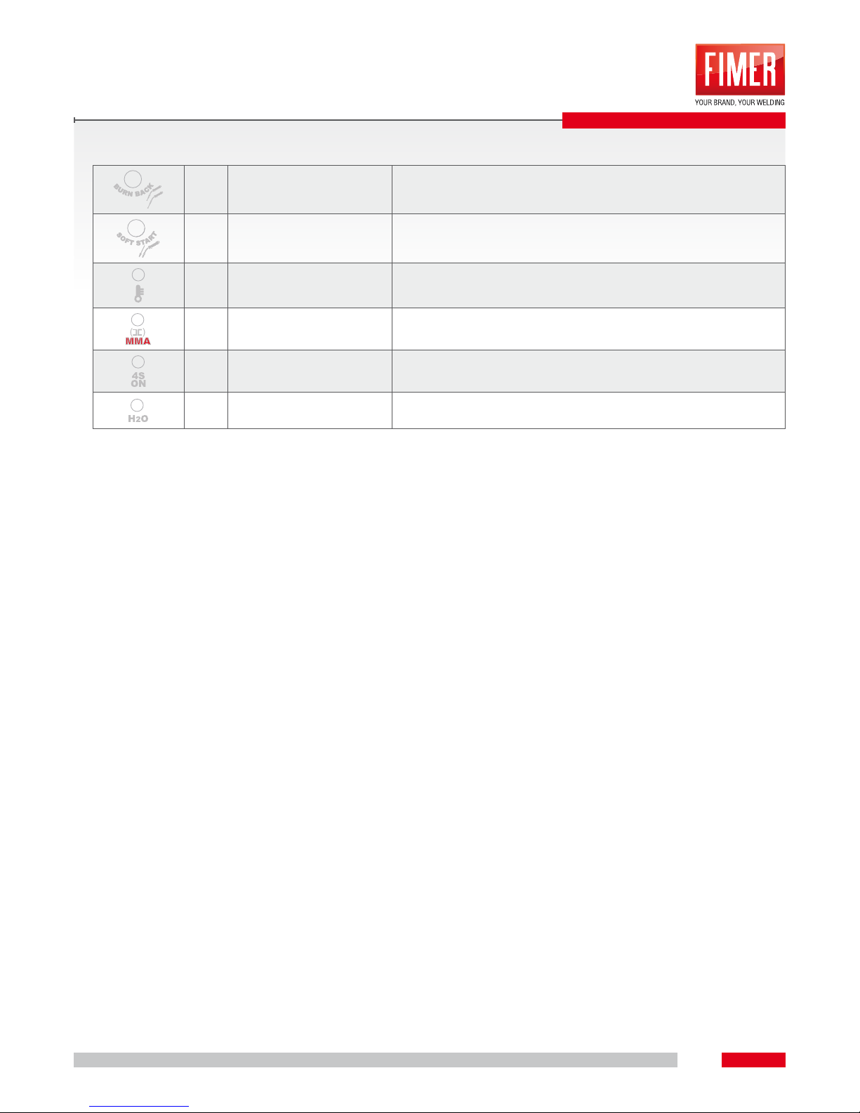
BURN BACK TIME
TRIMMER REGULATION
It allows to change the wire length on top of the torch at the end of
welding.
11
SOFT START TRIMMER
REGULATION
It allows to modify the wire approaching speed to obtain a welding
trigger softer or speeder.
12
DL17
ERROR NOTIFY LED
13
DL1
INVERTER ON/MMA MODE
NOTIFY LED
14
DL2
MODE TORCH NOTIFY
LED
15
DL3
COOLING UNIT ON NOTIFY
LED
Page 15
15
4
FUNCTIONING
4.1 EQUIPMENT COOLING
To obtain an optimal duty cycle of the machines please observe the following conditions:
• Assure an adequate ventilation in the workplace
• Leave open the inow and outow openings of the welding machine
• Pay attention to avoid metallic parts, powder and other external parts enter into the machine
4.2 EARTH CABLE
Burn danger after inappropriate connection of earth cable!
The presence of paint, rust and impurities on connection points prevent current ux and can cause
vacant welding currents.
Vacant welding currents can cause res and personal injuries!
• Clean the connecting points!
• Safely connect the earth cable!
• Do not use the structural parts of the piece to weld as welding current return conductors!
• Assure a perfect current conduction!
4.3 ELECTRICITY CONNECTION
Inappropriate connection risks!
An inappropriate connection can cause material and personal damages.
• Exclusively activate the equipment by a grip with right connected conductor.
• If necessary connect a new network conductor, this installation must be done by a specialized
electrician in conformity with local laws and dispositions.
• Connector, grip and network supply must be checked at regular intervals by a specialized electrician.
Page 16
FUNCTIONING
16
4
4.4 SHIELDING GAS SUPPLY
Injuries danger caused by overthrow of the gas protection cylinders!
Gas protection cylinders can overturn in case of inadequate xing and seriously injure people!
• Assure the protection gas cylinders by the available protection elements provided on trolleys
• Protection gas cylinders must join rmly to the matching circumference!
• On the protection gas cylinder valve must not be any xing element!
4.5 SHIELDING GAS QUANTITY REGULATION
Wrong use of protection gas cylinders
A wrong use of protection gas regulation can cause hard injuries and death.
• Follow the gas manufacturer indications and the suggestions for pressured gas!
• Install the gas cylinder in the arranged seat and assure it by protection elements!
• Avoid overheating of protection gas cylinder
4.6 MIG/MAG WELDING SHIELDING GAS SETTING
WELDING PROCESS RECOMMENDED PROTECTION GAS QUANTITY
MIG WELDING Ø WIRE x 11.0 = l/min
MAG WELDING Ø WIRE x 11.0 = l/min
ALLUMINIUM WELDING Ø WIRE x 13.0 = l/min (100% Argon)
NOTE: Both low and high settings can let air penetrate into welding pool, causing
the making of pores.
Gas quality MUST be adapted to the welding work type.
Page 17
17
5
5.1 TORCH PREPARATION
Depending on the welding wire diameter and the wire electrode type it has to be used a spiral liner
or a plastic/Teon/graphite liner with an internal diameter adequate to the welding torch and the
used wire.
Suggestion:
• For the welding of hard wire electrodes (steel) use a spiral sheath
• For the welding or the brazing of soft wire electrodes use a plastic/Teon/graphite liner
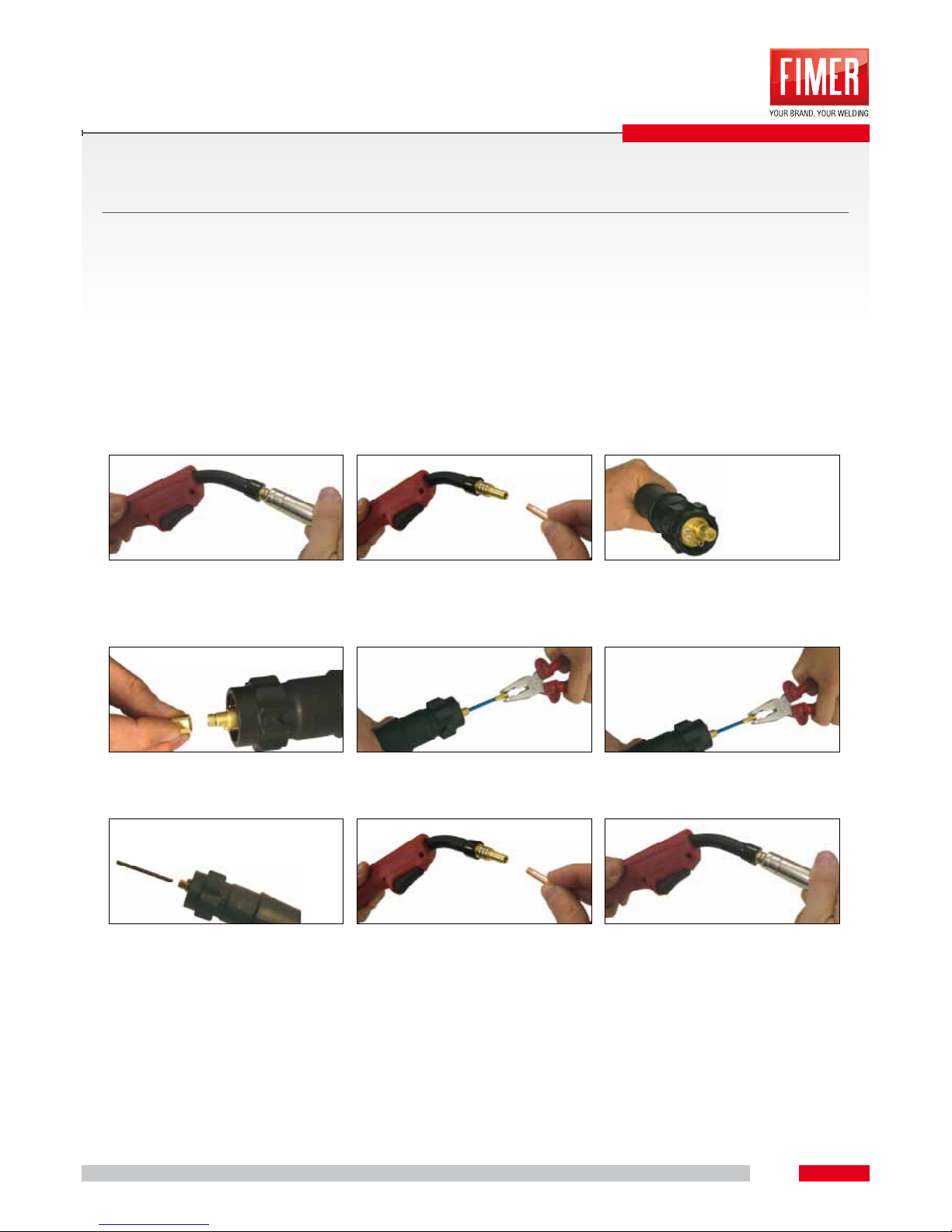
In case of wire feeder sheath replacement carefully follow these instructions:
A B C
Torch side: remove the gas nozzle
(A)
Unscrew the wire guide tip(B) Connector side (C)
D E F
Unscrew the termination nut (D,E) Complete the sheath extraction (F) Grab the sheath end by a nipper and
start to extract it (F)
G B A
Insert the new sheath and push it
deep inside (G)
Screw in again the wire guide tip on
the torch
Complete the replacement of the
sheath by using gas nipple (A)
During this operation assure to do not lose the O-RING ( gum topping) which guarantees the capacity
without gas leaks.
MIG-MAG WELDING
Page 18
MIG-MAG WELDING
18
5
5.2 TORCH AND EARTH CABLE INSTALLATION
•
Insert the central connector into the main connection of the welding torch and screw in with hexagon nut
• Insert the earth cable connector into welding current grip “-“ (MIG/MAG) “+” (no gas wire) and x it.
• Insert welding current wire and select the polarity in welding current grip “+” (MIG/MAG) “-“ (no gas wire)
5.3 WIRE SPOOL HOUSING
•
Open the top of the wire feeder unit
• Stake the hexagon screw of the xing and braking unit until the screw is completely staked from the
wire spool housing thread (do not extract the screw to avoid losing little components)
• Pre-compress xing and braking unit by hexagon screw into the wire roll housing with 4 complete
rotations (4x360°) in clockwise.
NOTE: When You make a change of the wire diameter it is necessary to be sure that the correct wire
feeder cave is faced inside the machine. To make this verify if the diameter value and type of wire are
readable (facing the external of the machine). Reminder: rolls are equipped by a “V” cave adequate
to dragging steel and iron wires. “U” cave rolls are adequate for aluminum wires.
Attention: Before proceeding with the following steps please verify if the torch cable is well stretched
and welding wire has not corners. If You do not take this precaution the wire guide sheath inside the
torch could be damaged.
Once You let the wire ow into the torch, x again the wire guide tip and the gas nozzle/diffuser
Page 19
MIG-MAG WELDING
19
5
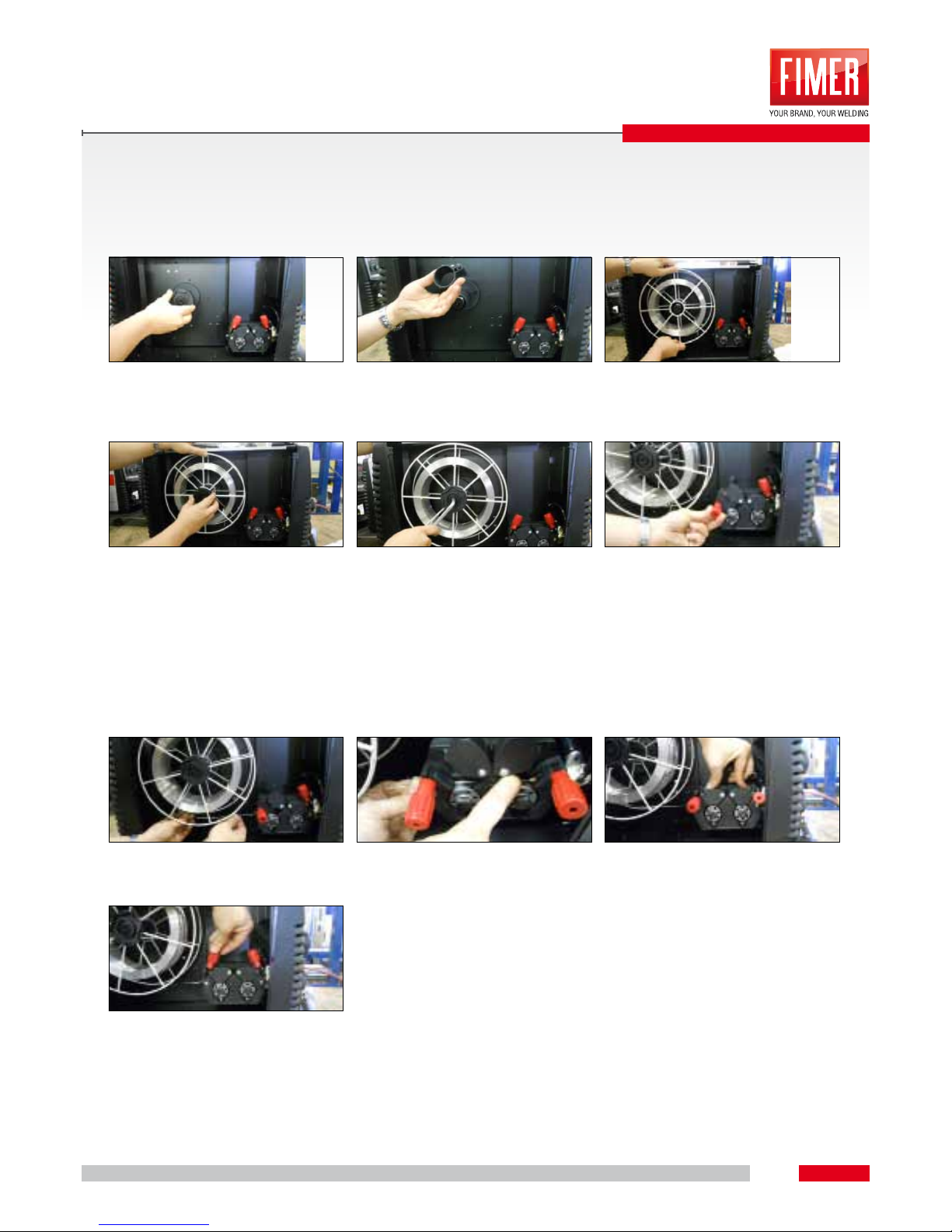
Attention: Before starting the wire installation steps, always remove the gas nozzle/diffuser and the wire
guide tip from welding torch. Disconnect the electrical supply cable.
A B C
Unscrew the knob placed at the center of
the welding wire roll.
Eventually remove the spacer depending
on the roll’s dimensions.
Remove the plastic protection of new roll
and place it on the dened support.
D E F
Re-assemble the knob. Pay attention to the hex (M8) placed in
the center of roll support which is the friction system of wire.
Screw in the hex to obtain a good friction:
If You x hard the friction is excessive
and arrests the normal unrolling of the
roll. Otherwise a low braking makes the
wire unrolls itself accidently at the end of
welding.
Unscrew the knobs of the wire feeder
group and let them turn. In this way they
will lift the upper wire feeders.
G H I
Insert the wire into the wire feeder engi-
ne capillary tube .
Let the wire ows under wire feeder rolls
until the entrance of euro connector.
Reduce the upper rolls and close the
wire pressure regulation plastic knob.
L
Tight carefully the knob. If it is too narrow the wire will block; otherwise if it is too
slack it won’t be able to drag the wire.
Repeat the operation also for the second milled knob.
Page 20
MIG-MAG WELDING
20
5
5.4 ROLLS REPLACEMENT
Danger of injuries due to welding wire escaping from welding torch!
• Welding wire can quickly escape from welding torch and cause injuries to face, eyes and other
body parts!
• Never point the welding torch to Yourself or to other persons!
• Danger of injury due to the presence of movable parts!
• Wire feeder devices are equipped by movable parts which can drag hands, hair, clothes or tools
with the risk to injury persons!
• Never touch components or rotary elements during motion!
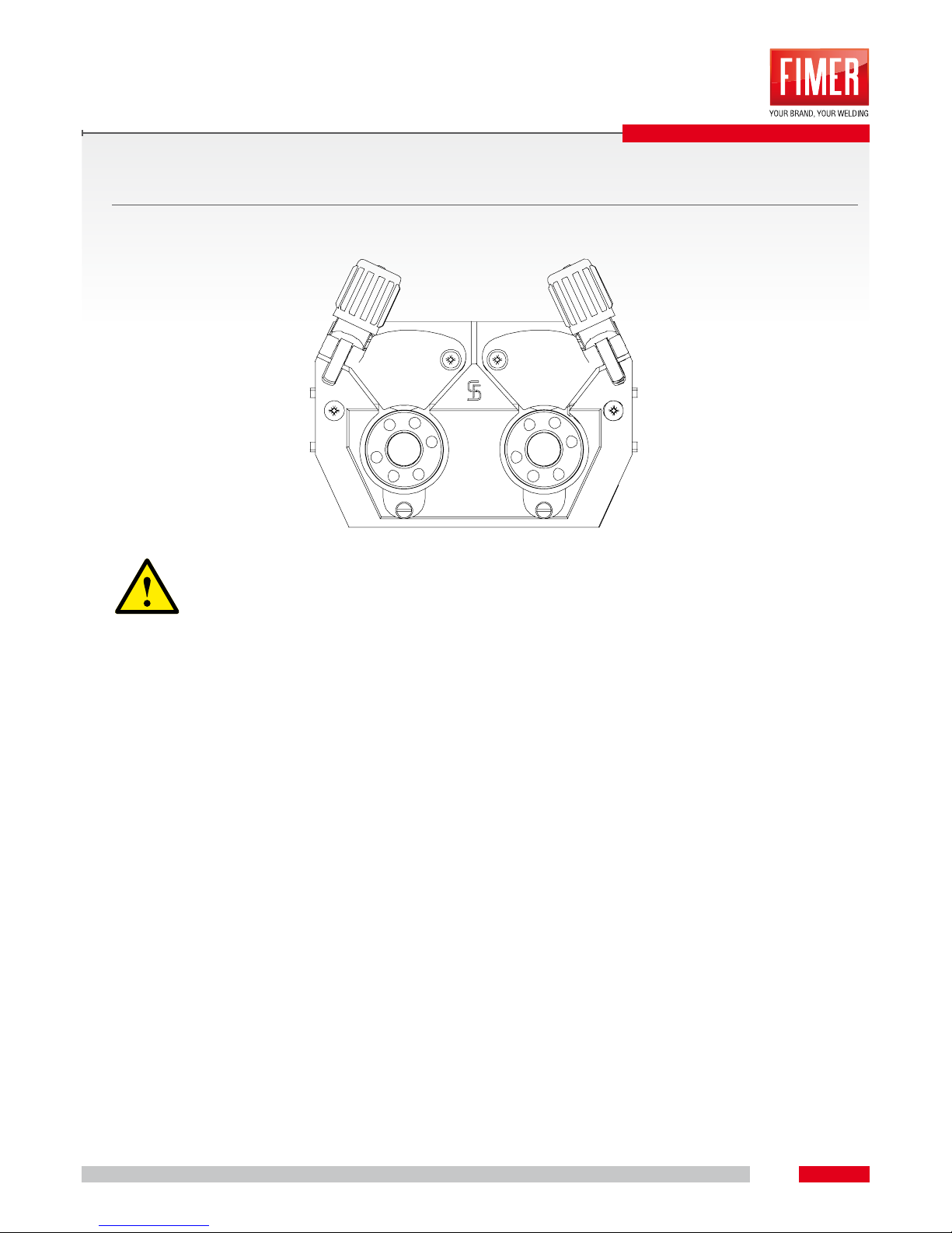
• Lay the torch beam tubes in stretch position
• Unlock and overturn pressure unit (tension unit with pressure rollers automatic overturn themselves
to above)
• Carefully unroll the welding wire from roll and insert it into capillary tube or into the Teon core
equipped by guide tube through the wire entry junction on feeding rolls slots and through guide
tube.
• Push below again the tension unit with pressure rollers and get up pressure units (electrode wire
must be placed into the feeding roll slot)
• Contact pressure on unit regulation nuts must be set to allow welding wire can be supplied but also
it can slide when wire roll is locked!
• Mainly front contact rolls pressure (during progress direction) must be more elevated than back
rolls.
• Push insert button until wire electrode comes out from welding torch.
Page 21
MIG-MAG WELDING
21
5
5.5 FUNCTION 2T
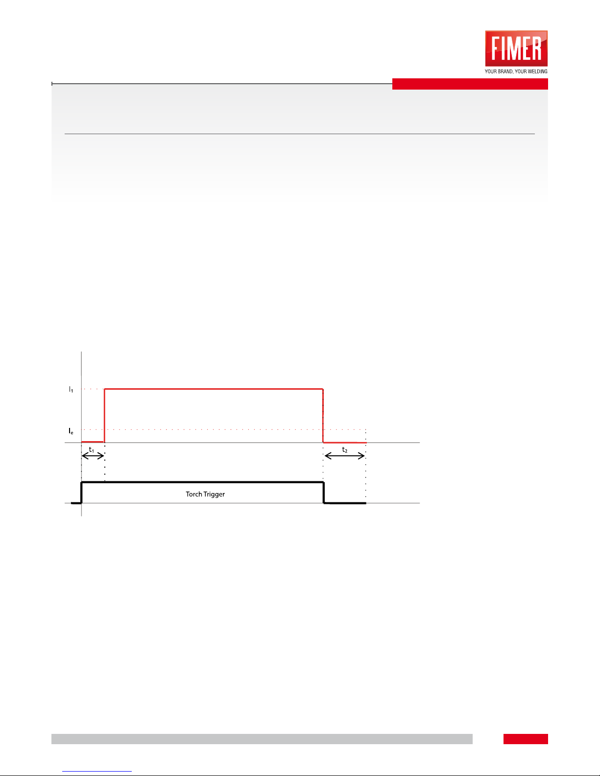
STEP 1
• Press and hold on torch trigger.
• Shielding gas is out of the torch (gas pre-ow).
• Wire feeder motor runs at “soft start speed”.
• Arc ignites after the wire electrode makes contact with the workpiece, the welding current ows.
• Change over to pre-selected/main wire speed.
STEP 2
• Release torch trigger.
• Wire feeder motor stops.
• Arc is extinguished when adjusted wire burn-back time expires.
• Gas post-ow time passes.
t1 = PRE GAS
t2 = POST GAS
Page 22
MIG-MAG WELDING
22
5
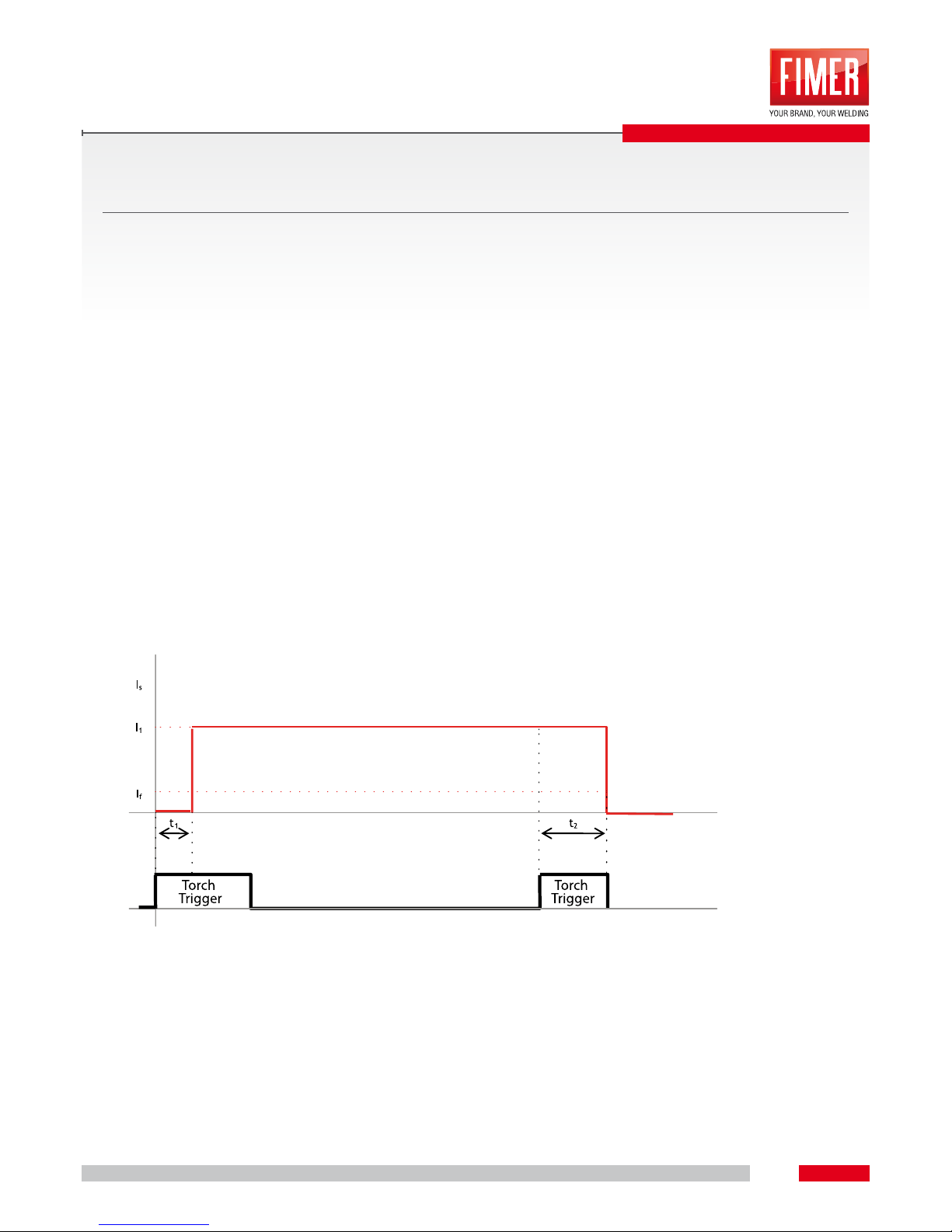
5.6 FUNCTION 4T
STEP 1
• Press and hold on torch trigger.
• Shielding gas is out of the torch (gas pre-ow).
• Wire feeder motor runs at “soft start speed”.
• Arc ignites after the wire electrode makes contact with the workpiece, the welding current ows.
• Change over to pre-selected/main wire speed.
STEP 2
• Release torch trigger (without effects).
STEP 3
• Press torch trigger (without effects)
STEP 4
• Release torch trigger.
• Wire feeder motor stops.
• Arc is extinguished when adjusted wire burn-back time expires.
• Gas post-ow time passes.
t1 = PRE GAS
t2 = POST GAS
I1 = WELDING CURRENT
Page 23
23
6
MMA WELDING
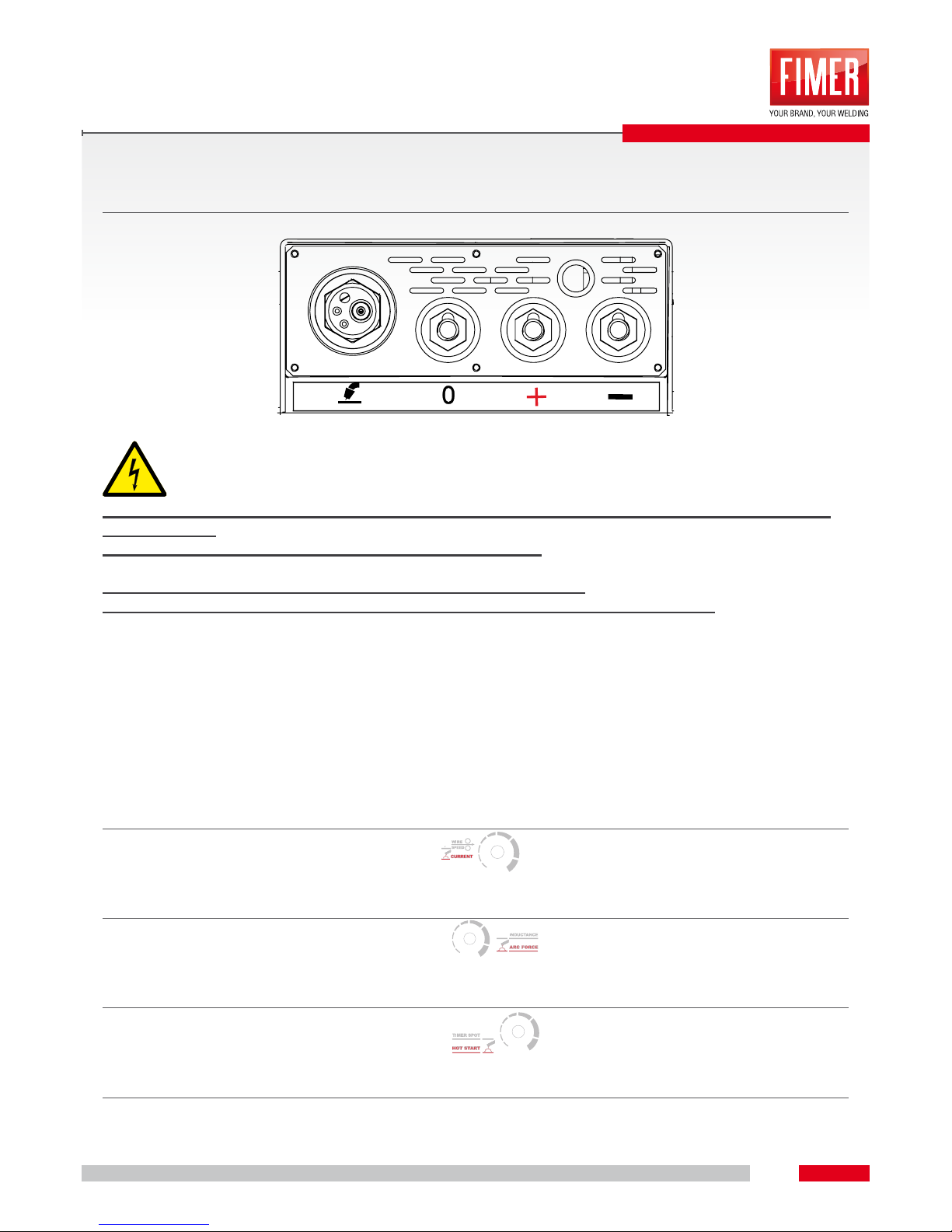
6.1 CONNECTING THE ELECTRODE HOLDER AND THE EARTH CABLE
EXTERNAL ACCESSIBLE LIVE PARTS UNDER VOLTAGE (Negative AND Positive Terminal FastConnect Plug).
WARNING OF HIGH VOLTAGE ELECTRIC SHOCK INJURY
NB: the manufacturer indicates polarity on electrodes’ package
NB: special electrode holders and carbon electrodes are necessary for gouging
Installation:
• Insert the electrode holder’s cable into either the “ + ” or “ - “ welding current socket and lock it by
turning it clockwise.
• Insert the earth cable’s connector into either the welding “ + ” or “ - “ welding current socket and lock
it by turning it clockwise.
• Place polarity cable for euro connection socket into “ 0 ” rest position.
6.2 WELDING CURRENT MANUAL SELECTION
Select welding current through the “EN1” knob.
6.3 ARC FORCE
Select welding current through the “POT3” knob.
6.4 HOT START
Select welding current through the “POT4” knob.
6.5 ANTISTICKING
Antistick device prevents electrode’s burning.
If the electrode sticks in spite of Arc Force device, then the machine automatically cuts the current in 2
seconds to avoid electrode’s burning.
Page 24
24
NB. Not all errors are present on in this manual. Some errors and alarms are specic for the welding process used,
which should be not available on this model.
7
ALARMS/TROUBLESHOOTING
7.1 ERROR MESSAGES
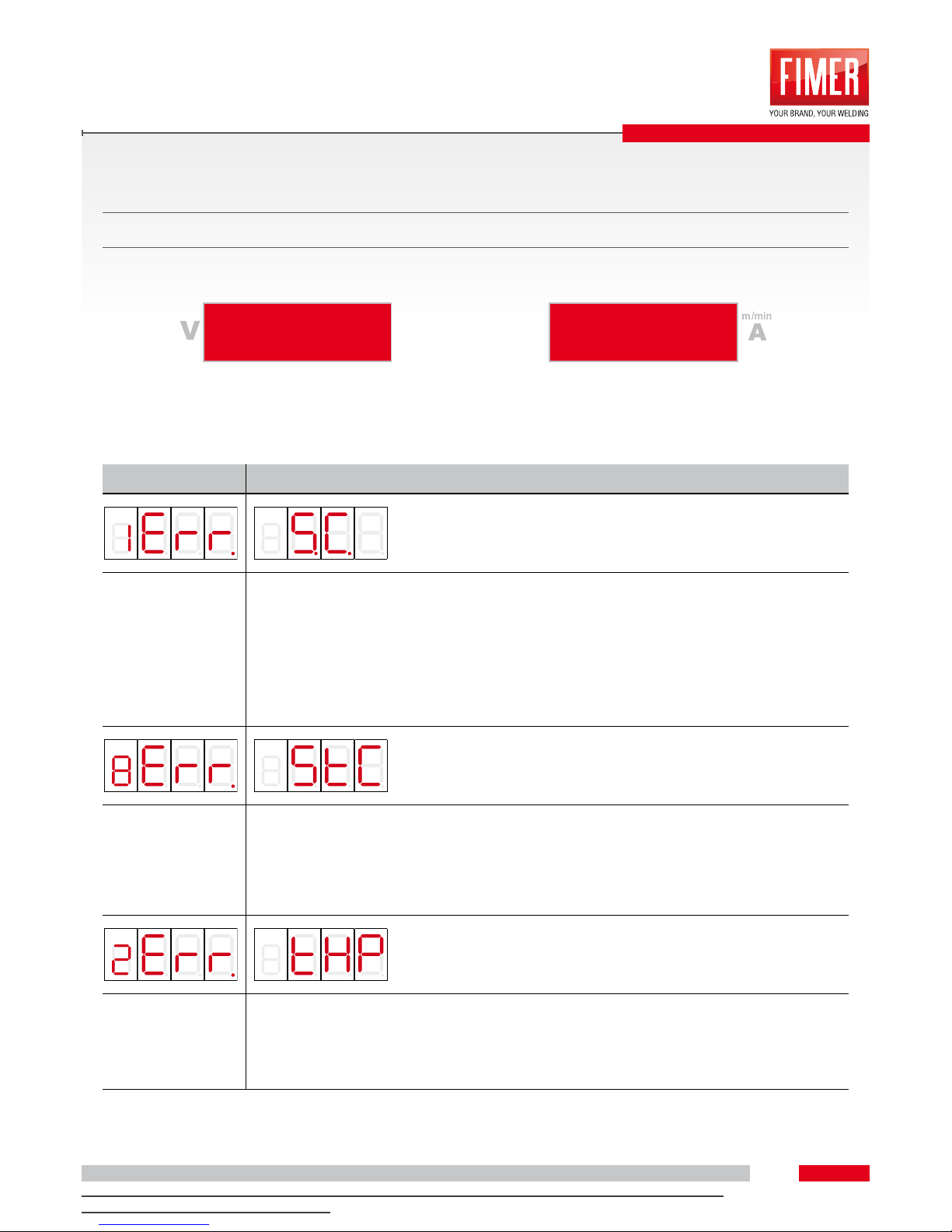
Here are led signal errors:
DESCRIZIONE
Short-circuit error “Err. S.C.”.
This error can occurs only when the machine is welding in MMA.
Changing from MIG modality to MMA modality if the electrode makes contact with the workpiece or with another metal surface, then the short-circuit error appears which prevents
inverter starting.
Error solving:
To cancel the error you need to switch off and switch on again the machine after eliminating
the error condition.
Antisticking error “Err.StC”.
This error can occurs only when the machine is welding in MMA.
This error occurs if during the welding process ao the start phase the electrode sticks to the
workpiece.
Error solving:
The machine will start again to function after detaching the electrode from the workpiece.
Thermal overload error “Err. tHP”.
This error occurs when the machine is in thermal overload due to an excessive overheating
Error solving:
The machine will start again to function when temperature will decrease up to an uncritical
value.
Page 25
ALARMS/TROUBLESHOOTING
25
7
NB. Not all errors are present on in this manual. Some errors and alarms are specic for the welding process used,
which should be not available on this model.
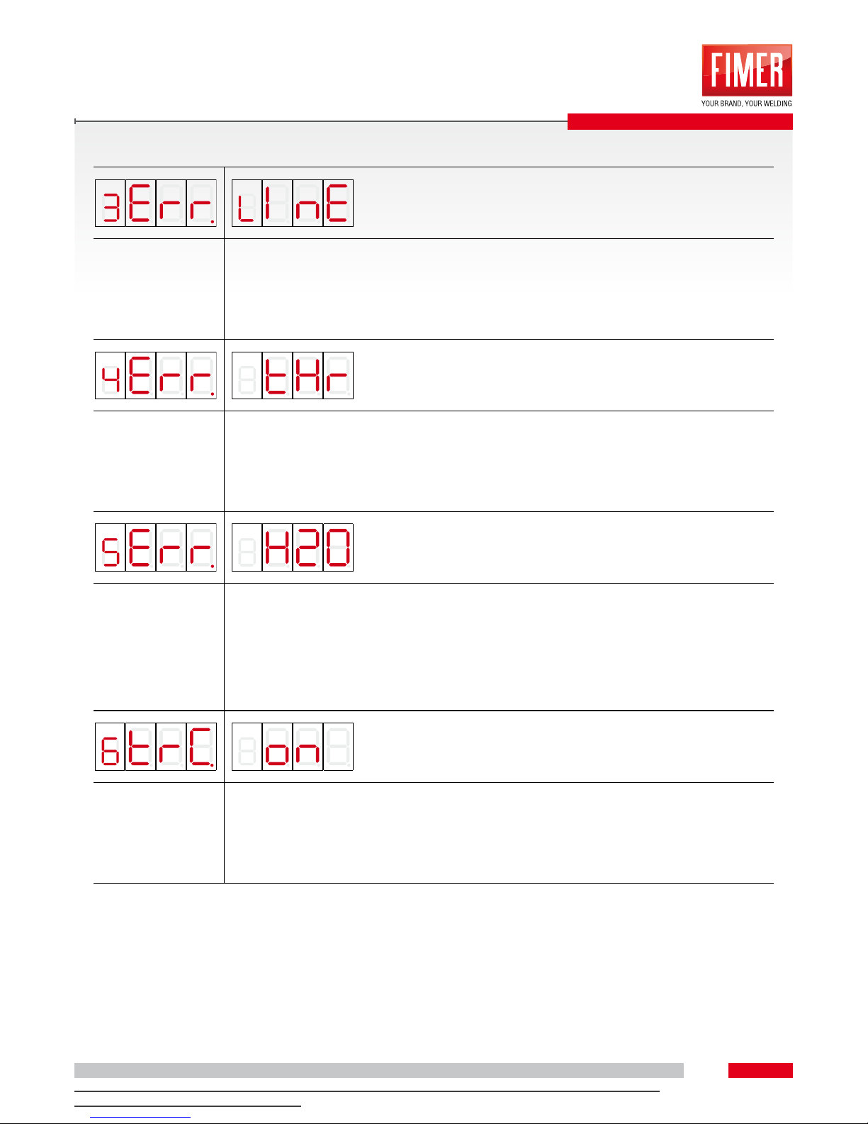
Undervoltage error “Err. LInE”.
This error occurs when the machine measures undervolatge condition.
Error solving:
The machine will start again automatically to function when the voltage grow up to an uncri-
tical value.
Thermal overload error “Err. tHr”.
This error occurs when the machine is in thermal overload due to an excessive overheat-
ing.
Error solving:
The machine will start again to function when temperature will decrease up to an uncritical
value.
Low coolant level error “Err. H2O”.
This error can appears only if the machine works in MIG/MAG mode. If the water cooling
unit is switched on, the error occours if there are leak in the coolant circuit, less water into
the tank, coolant pump is not working, sensor damaged.
Error solving:
The machine will start again to function when the error is solved, the water cooling unit is
switched off by the button on front panel and turn on again.
Torch button pressed “trC on”.
MIG/MAG torch button pressed during the machine switch on phase.
The error occours if the machine, in switch on phase, recognize that the torch button is
pressed.
Error solving:
Release the torch button during this phase or check the torch.
Page 26
26
8.1 DAILY MAINTENANCE
• Supply cable and its discharge traction
• Welding current conductors (verify their locked and tight position)
• Gas tubes and their commutation devices (electric valve)
• Gas cylinder xing elements
• Use, alert, protection and position devices (functioning control)
• Various, general conditions
8.2 MONTHLY MAINTENANCE
•
Envelope damages (front, back, lateral sides)
• Adjustable wheels and their xing elements
• Transport elements (belt, eyebolts, handle)
• Step switches, control equipments, emergency arrest devices, tension adapter device, control and
alarm leds
• Verify the presence of impurities inside the cooling liquid exible tubes and into their connections
• Verify the tight position of wire guide elements (entry junction, guide tube)
In addition to the control rules here explained, it is necessary to observe local laws and disposals.
8.3 REPAIRS
Repair and maintenance acts must be done only by specialized and authorized persons.
Otherwise warranty right is declined. For everything You need assistance, please contact Your specialized
vendor. The replacement of under warranty products can be done only by Your own vendor. When You
replace components please use only original spares. When You order spare parts please indicate type of
machine, its code and serial number also code and model type of the spare part.
NB: As regarding the disposal please take a look at the bottom of this manual.
8
CARE AND MAINTENANCE
Page 27
27
9
9.1 SERVICE MENU
Our machines have a Service Menu and it is reachable by a combination of buttons. This menu allows to
modify some parameters to improve and/or customize Your machine depending on Your needs.
9.2 ENTERING IN SERVICE MENU
+
In the starting phase of the machine, it is necessary to push both wire charge (PU3) button and “2S/4S/
MMA” (PU1) button until the “MENU SERV” appears on display to enter the service menu.
By release the two buttons You will see the rst changeable welding parameter.
9.3 NAVIGATE IN SERVICE MENU
To scroll the service menu it will be enough to rotate the voltage setting knob (EN2) and the parameter
with its default value will be showed.
To modify this parameter value You can only turn wire speed/current setting knob (EN1).
After setting the parameter value You will have to push “2S/4S/MMA2” button to memorize it (PU1).
Pushing the button You will see on the display, where there is the parameter value, the script SAV for
few seconds to indicate that the parameter has been saved.
9.4 MENU LEGENDA
The settable parameters in service menu are different depending on MIG/MAG or MMA mode.
In case of MIG/MAG mode, the parameters are:
• Pre-gas time: “PRE” script is visualized. It is showed in seconds. Default value is 0,1s.Changeable
interval (0,1-5) seconds.
• Post-gas time: “POST” script is visualized. It is showed in seconds. Default value is 0,1s.
Changeable interval (0,1-5) seconds
• Hot start: “t C” script is visualized. It indicates the trigger current expressed in Ampere. Default value
is 370A. Changeable interval (150-400) Ampere.
• Hot start time: “TCS” script is visualized. It indicates the time of trigger current. It is expressed in
milliseconds. Default value is 8ms. Changeable interval (1-40) milliseconds.
• Trigger voltage: “TV” script is visualized. It indicates the trigger voltage expressed in Volt. Default
value is 18V. Changeable interval (5-30) volt.
• Motor ramp: “M r” script is visualized. It indicates motor speed variation from stopped to reference
speed. Default value is 50. Changeable interval (1-100).
• Detach current: “d C” script is visualized. It indicates the set current for drop detach at the end of
welding. It is expressed in Ampere. Default value is 400A. Changeable interval (370-420).
• Detach current time: “dCS” script is visualized. It indicates the time needed for detach current. It is
expressed in milliseconds. Default value is 4ms. Changeable interval (1-10) milliseconds.
• Minimum welding current: “M C” script visualized. It indicates the minimum settable current. It is
expressed in ampere. Default value is 15A. Changeable interval (5-50) ampere.
• Water cooling unit mode setting: this parameter appears only if the machine is equipped by water
cooling unit inside the torch. Starting the unit with on button, it can work in two modes: “ON” mode
SERVICE MENU
Page 28
SERVICE MENU
28
9
(always working) or “AUTO” mode (On when the welding process is On). You will see “PMP” “AUTO”
or “ON” on display. Default mode is “AUTO”.
• Restore default values: “rES” (reset) script is visualized. By turning the wire speed setting knob it
will appear ON” or “OFF” scripts. To restore MIG/MAG parameters default values set ON and conrm by pushing “2S/4S/MMA” button (PU1). .
9.5 MENU SERVICE EXIT
•
Menu service exit: if You see “ESC” script please push “2S/4S/MMA” (PU1) button to conrm
the exit from service menu and entering the normal functioning of the machine. In case of MMA con-
guration, the service menu parameters are:
• Hot start time : “Hot” script is visualized. It indicates hot start duration. It is expressed in seconds.
Default value is 0,5s.
Changeable interval (0,5-2) seconds.
• Default value restore: “rES” (reset)script is visualized. By turning the wire speed setting knob You
will see “ON” ore “OFF” scripts. To restore MMA parameters default values set ON and conrm by
pushing “2S/4S/MMA” button (PU1).
.
9.6 WATER COOLING UNIT SERVICE MENU
The water cooling unit is enabled in Simplex 420 and Simplex 320 as default.
To enter the service menu it is necessary to push at the same time the “wire feeder” button
(PU3)
and “on/off water cooling unit” button (PU2) , at the start of the machine until the
display turns off. By releasing the buttons it will appear “AAAA” script on the right, then You will
have to enter the password “F1M3”.
Turning the current regulation handle (EN1)
) the font will change on the display and the
choice will be conrmed by pushing “2S/4S/MMA” button (PU1)
. The conrmed font will be
replaced by “-“ font and You will be able to go on to the next font.
If the right password has been entered, at the end of this operation the unit will be enabled if it
was disabled (PMP ENA), otherwise it will be disabled (PMP dlS) if it was enabled.
In case the entered password is wrong, the script “AAAA” will appear again on display.
After this it will be necessary to stop the machine and so exit from service menu.
Page 29
29
10
10.1 TROLLEY
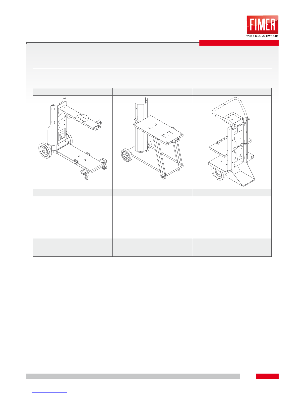
There are different types of trolley according to the nal use:
C7s C9 C11
580.690.008 580.690.005 580.690.007
P
It provides the installation of
water cooling system WCS1
(580.520.053) and toolsbox)
(580.690.100)
P
Without water cooling system)
P
it provides only the installation
of water cooling system WCS2
(580.521.053) - without toolsbox
WxLxH
570x1090x1010 mm
32 kg
WxLxH
475x975x1005 mm
22 kg
WxLxH
600x565x1200 mm
30 kg
ACESSORIES
Page 30
ACESSORIES
30
10
10.2 TOOLSBOX
You can use the Tools Box only with trolley C7s cod. 580.690.008 and it’s an alternative to the water
cooling unit (it isn’t possible to install both accessories under the welding machine).
TOOLSBOX
580.690.100
260x680x260 mm
25 kg
10.3 WATER COOLING UNIT (WCS1 - WCS2)
Depending on the trolley selected, you can choose the following units of cooling:
WCS1 WCS2
580.520.053 580.521.053
2 Ph - 400V
260x680x260 mm
25 kg
2 Ph - 400V
260x640x260 mm
23 kg
Page 31
ACESSORIES
31
10
10.4 ACCESSORIES
ITEM NR.
DESCRIPTION
KIT CABLE
049.600.055
Cable with earth clamp 25 mm2 - dinse 50 mm2 - 3 m
049.600.056
Cable with earth clamp 35 mm2 - dinse 50 mm2 - 3 m
049.600.057 Cable with earth clamp 50 mm2 - dinse 50 mm2 - 3 m
280.500.004 Gas regulator 2 manometers macro CO2/Argon
KIT AIR
043.600.143 Torch F36 - 4 m
KIT H2O
043.600.144 Torch F51 H2O - 3 m
043.600.145 Torch F51 H2O - 4 m
043.600.146 Torch F51 H2O - 5 m
ACCESSORY MMA
489.603.413 Cables set complete 50 mm2 - dinse 50 mm2 - L=3+2
ROLLS
422.510.002 Roll 0,8-1,0 D.3 - V groove (steel, stainless steel) STANDARD
422.520.002
Roll 1,0-1,2 D.37- V groove (steel, stainless steel) included 2x
422.520.003 Roll 1,2-1,6 D.37- V groove (steel, stainless steel)
422.520.004 Roll 0,8-1,0 D.37 - U groove (aluminium)
422.520.051 Roll 1,0-1,2 D.37 - U groove (aluminium)
422.520.052 Roll 1,2-1,6 D.37 - U groove (aluminium)
422.520.053 Roll 1,0-1,2 D.37 - U groove (aluminium)
422.520.101 Roll 1,2-1,6 D.37- U groove (ux cored)
422.520.102
Roll 1,6-2,4 D.37 - U groove (ux cored)
Page 32

32
11
NOTE
Page 33

33
11
NOTE
Page 34

34
11
NOTE
Page 35
35
12
12.5 DISPOSAL
This product contains electrical or electronic materials.
Fimer as producer of electric and electronic components is in compliance with the European directive
2012/19/UE following the italian DLGS 14 march 2014 N°49.
The presence of these materials may have, if not disposed properly, potential adverse affects on the
environment.
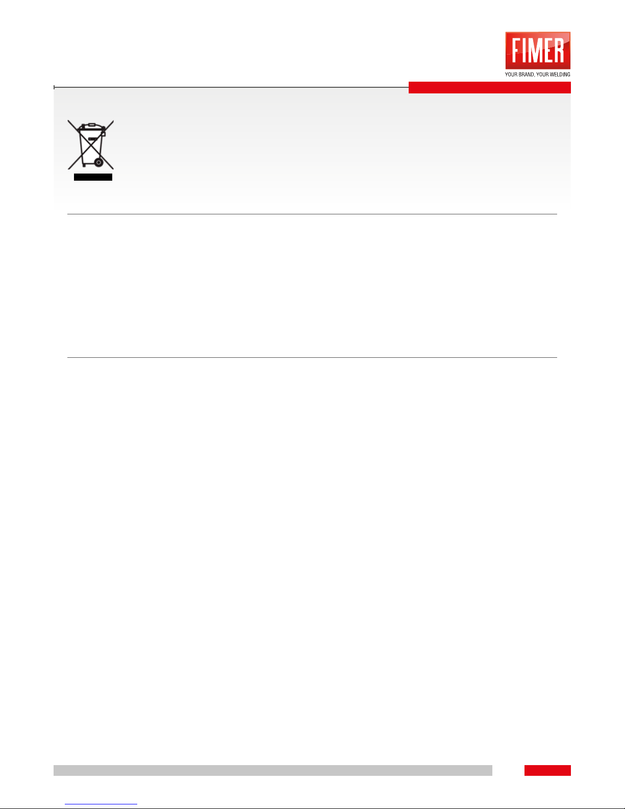
Presence of this label on the product means it must not be disponed in normal household waste and
must be disposed separately.
As a consumer you are responsible for ensuring that this product is disposed properly.
If your supplier offers a disposal facility please use it or alternatively contact your local authority/council
to nd out how to properly dispose this product.
DISPOSAL
Page 36
+39-039-6079326
Telefono +39-039-6079326
Fax +39-039-6079334
ASSISTENZA TECNICA:
service.welding@mer.com
LUNEDì - VENERDì
09.00 - 12.30
15.30 - 17.00
Via J.F. Kennedy - 20871 Vimercate (MB) Italy
Phone: +39 039 98981 | Fax +39 039 6079334
www.mer.com | info@mer.com
 Loading...