


910.100.539GB REV01
Ed. 2016_05_03
KRONOS
500
dual-pulse
INSTRUCTION MANUAL

Original instructions
Via J.F. Kennedy - 20871 Vimercate (MB) Italy
Phone: +39 039 98981 - Fax: +39 039 6079334
www.fimer.com - info@fimer.com
INFOLINE: Tel.+39 039 6079326
WELDING TECHNICAL SERVICE
service.welding@fimer.com
CERTIFICATI
N°1617 ISO 9001
N°1618 ISO 14001
N°1619 BS OHSAS 18001
BEFORE USING THIS EQUIPMENT IT IS RECOMMENDED TO READ THIS INSTRUCTION MANUAL!
IN CASE OF MISSING READING, CASES OF FAILURE AND/OR DANGERS FOR THE USER COULD
HAPPEN!
THE UNIT CAN ONLY BE USED BY PEOPLE WHO PERFECTLY KNOW THE SPECIFIC SECURITY RULES!
This manual is an integrant part of the equipment and it must be attached in every displacement or resale.
It is user’s responsibility to keep it intact and in good conditions.
The manufacturer has the right to apply modifies in every moment or without any forewarning.
Every Fimer product is minded, designed and produced in Italy in our sites.
This is guarantee of high quality and reliability.
Translation, production and adaptation rights, total or partial and with every mean (photostatic copies, film and microfilm
included) are reserved and banned without the written authorization of the manufacturer.
DEGREE OF 'WORK ENVIRONMENT POLLUTION: CLASS 3

DICHIARAZIONE DI CONFORMITÀ CE
CE DECLARATION OF CONFORMITY
KONFORMITÄTSERKLÄRUNG CE
DÉCLARATION DE CONFORMITÉ CE
DECLARACIÓN DE CONFORMIDAD CE
DECLARAÇÃO DE CONFORMIDADE CE
FÖRSAKRAN OM OVERENSSTAMMELSE CE
VERKLARING VAN CONFORMITEIT CE
BEKREFTELSE OM OVERENSSTEMMELSE CE
OVERENSSTEMMELSESERKUERING CE
YHDENMUKAISUUSVAKUUTUS CE
UYGUNLUK BİLDİRİMİ CE
Si dichiara che l’apparecchio tipo
We hereby state that the machine type
Wir erklären, dass das Gerät Typ
On déclare que la machine type
Declara que el aparato tipo
Declara-se que a máquina tipo
Vi försakrar att maskinen av typ
Verklaard wordt dat het apparaat type
Vi bekreftelser, at maskinen type
Vi erklrerer, at maskinen type
Todistamme etta laite mallia
Yandaki makine modellerinin
è conforme alle direttive
is in compliance with the directives
den Richtlinien entspricht
est conforme aux directives
es conforme a las directivas
é conforme as directivas
ar i överensstammelse med direktiven
overeenkomstig de richtlijnen
er i overensstemmelse med direktivene
er i overensstemmelse med direktivene
on yhdenmukainen direktiivissa
yandaki direktiflere ve
MODEL
EN60974-1
EN60974-10
Uffici : Via J.F. Kennedy
20871 Vimercate (MB) Italy
Phone: +39 039 98981
Fax: +39 039 6079334
web site: www.fimer.com
e-mail:
info@fimer.com
INFOLINE
tel. +39 039 6079326
WELDING TECHNICAL SERVICE
service.welding@fimer.com
VIMERCATE
03.02.2016
2006/42/CE
2014/35/CE
2014/30/CE
2011/65/UE
(RoHS)
Ogni intervento o modifica non autorizzati dalla FIMER faranno decadere la validità di questa dichiarazione.
Any tampering or change unauthorized by FIMER shall immediately invalidate this statement.
Eingriffe und Änderungen ohne die Genehmigung von FIMER machen die vorliegende Erklärung ungültig.
Toute opération ou modification non autorisées par FIMER feront déchoir la validité de cette déclaration.
Cualquier intervención o modificación no autorizadas por FIMER, anularán la validez de esta declaración.
Qualquer intervenção ou modificação que não seja autorizada pela FIMER anularà a validade desta declaração.
Denna försakran upphör att galla vid eventuella ingrepp eller andringar som ej ar godkanda av FIMER.
ledere niet door FIMER geautoriseerde ingreep of wijziging doet de geldigheid van deze verklaring vervallen.
Denne bekreftelse bortfaller ved evt. inndgep eller endringer, som ikke er godkjent al FIMER.
Denne erklæring bortfalder ved evt. indgeb eller ærendringer, der ikke er godkendt afæ FIMER.
Jokainen valiintulo tai muutos ei valtuutettu FIMER rappldittaa k’fseisen lausunnon pitavyyden.
FIMER’in onayı olmaksızın yapılacak her türlü kurcalama ve değişiklik yukarıdaki bildirimi geçersiz kılar.
è conforme alle norme
is in compliance with the rulls
den Normen entspricht
est conforme aux normes
es conforme a las normas
é conforme as normas
ar i överensstammelse med direktiven
overeenkomstig de richtlijnen
er i overensstemmelse med direktivene
er i overensstemmelse med direktivene
on yhdenmukainen direktiivissa
yandaki normlara uygun olduğunu
bildiririz
AMBROGIO F. CARZANIGA
CHAIRMAN
16.05.2016
KRONOS 500 dual-pulse

Dear Customer,
by thanking for Your choice, Fimer welcomes you.
Fimer products are characterized by a modern inverter technology, an innovation of process and extreme simplicity
of use. All to guarantee a sure result and efficient guardianship of the user.
At the end of the productive process, every equipment is tested on welding/cuting in our laboratories. The continuous
r&d to improve the technology and the optimization of the process have driven us on top of the market.
Our production, assistance and training site is exclusively on Italian region and we can praise a 100% MADE IN
ITALY. In addition, Fimer has inside a complete production chain thanks to an efficient and high quality metal
carpentry department, lines for the production of electronic boards with SMD technology and testing/assembly
department which make possible to create the entire product.
To be able to reach the best welding processes and guarantee a reliable and long lasting use of the equipment,
it is very important to observe our indications included in the present manual.
Trusting that our product will meet all Your expectations, we thank You for the given trust.
Best regards,
Ambrogio F. Carzaniga
Chairman

ENGLISH

KRONOS 500 dual-pulse
5T5.555.452

ENGLISH
DANGER
(Indicating a hazard that could cause injury or damage)
READ THE INSTRUCTION MANUAL
ELECTRIC SHOCK
(Indicating the danger of electric shock)
DANGER OF FIRE.
DANGER EXPLOSIONE RISK
Indicating the risk of explosion in the event of improper handling
or maintenance of compressed gas cylinders or regulators
HOT SURFACE
Do not touch the surface
HOT SLAG
Indicating the risk of being burned by hot slag
EYE PROTECTION
Indicating that eye protection is required to avoid flying
debris
Indicating that eye protection is required to avoid
burns and eye damage.
MANDATORY USE GLOVES
NOISE POLLUTION
Required to wear hearing protection
FIRE
PRECAUTIONS
DISPOSAL
INFORMATION
INSTALLATION
INSTRUCTIONS
UNPACKING
INSTRUCTIONS
SUITABLE FOR ENVIRONMENT WITH INCREASED
HAZARD OF ELECTRIC SHOCK
ELECTROMAGNETIC FIELDS
DANGER CYLINDER PRESSURE
INHALED DANGER EXHAUST GASES
IMPORTANT INFORMATION
Indicating the precautions to be taken when installing and
using the unit.
HANDLE WITH CARE
GROUND CONNECTION
s
SAFETY WARNING
SAFETY WARNING
This equipment is designed solely for industrial or
professional use. As such, only experienced or ful-
ly-trained people should use the equipment. The
user and/or owner is responsible for ensuring inexperienced personnel does not have access to the equipment.
A workman must look after his tools carefully !
Remember that any tool or equipment can become
a hazard if it is not looked after properly. Equipment
in a state of disrepair or neglect can be dangerous. If it does not
operate properly or overheats, the electricity supply should be
removed immediately and the unit should be returned to the
supplier for repair.
Read this manual carefully before using your Welder. You
can then do a better and safer job. By reading this manual
you will learn more about the possibilities, limitations and
potential dangers of welding. Retain this manual for the entire
life of the equipment. It should be kept within the operator’s
reach at all times.
All equipment connected to electric power supplies
can be dangerous if the manufacturers instructions
are not read and observed. Read, understand and
observe these safety instructions to reduce the risk of death or
injury from electric shock. Ensure that even bystanders are aware
of, and understand, the dangers that exist in the welding area.
The safety information contained in this manual is a guide
to ensure you are not subjected to unnecessary risks.
However, the operator must be competent and careful at
all times.
The constructor declines all responsibility for injury or
damage caused by inexperienced, improper or neglectful
use of its equipment.
Fires and explosions can seriously injure or cause
damage ! Read, understand and observe all safety
warnings to reduce the risk of death or injury from fire
or explosion. Pay particular attention to the fact that even bystanders
should be aware of, and understand, the dangers existing in the
welding area. Remember that welding, by nature, produces sparks,
hot spatter, molten metal drops, hot slag and hot metal parts that
can cause fires, can burn skin and damage eyes.
Arc rays can damage your eyes and burn your
skin ! Read, understand and observe all safety
warnings to avoid damage from arc rays. Pay
particular attention to the fact that even bystanders should be
aware of, and understand, the dangers existing in the welding
area. Wear a protective mask and make sure bystanders do the
same.
Fumes, toxic gases and vapours can be harmful !
Read, understand and observe all safety warnings to
avoid harm from toxic welding gases. Pay particular
attention to the fact that even bystanders should be aware of, and
understand, the dangers.
Carelessness while using or maintaining the compressed
gas cylinders or regulators can injure or kill the operator
and/or bystanders ! Read, understand and observe
all safety warnings to avoid the dangers of compressed gas. Pay
particular attention to the fact that even bystanders should be
aware of, and understand, the dangers.
HIGH VOLTAGE The unit carries potentially lethal voltage.
The high voltage areas of the equipment have been segregated
and can be reached only by using tools that are not provided
with the Welder. All maintenance or repair operations requiring
access to such areas may only be performed by constructor-trained
technicians.
WARNING SYMBOLS
WARNING SYMBOLS
CAUTION
CAUTION

FOREIGN OBJECTS Never block the air vents with
foreign objects and avoid any contact with liquids.
Clean using just a dry cloth. These safety precautions
apply even when the unit is switched off.
WEIGHT LOADS The upper part of the Welder was
not designed to withstand heavy loads. Never stand
on the unit.
CABLE GAUGES Check that all cables are
appropriately gauged for the input power required
by your specific Welder. This precaution applies
also to extension cables, if used. All extension cables must be
straight. Coiled cables can overheat, becoming dangerous. Twisted
or coiled cables can also cause Welder malfunction.
OVERLOAD PROTECTION Check that the power
source supplying the Welder carries the correct voltage
and is safety-protected. The power switch must open
all the power supply circuits. (If a single-phase connection is used,
both the live and the neutral poles must be open. If a three-wire
connection is used , all three poles must be open. Four-wire circuits
require all poles and neutral open). Time-delayed fuses or Kstandard circuit breakers should be used.
EARTHING If the Welder was not already supplied with a
plug, connect the earth wire first. When removing the plug,
disconnect the earth wire last.
PLUG AND POWER SUPPLY If the Welder already has a plug
attached, check that it is appropriate for the wall-socket you
intend using. Never tamper with the power cable.
CABLE COLOURS The green-yellow wire is for earthing.
(Don’t use it for anything else !)
RELOCATION 1 Some Welders are extremely heavy therefore
care should be taken when relocating the unit. Check the floor
or platform weight load limitations before relocating the unit if
the Welder is to be used, even only temporarily, in a non-industrial
environment
RELOCATION 2 Never store or move the Welder in an inclined
position or on its side.
INSTALLATION ENVIRONMENT The equipment is not
suitable for use in washrooms, shower cubicles, pool
areas or similar environments. If you are obliged to use
the unit in such areas, turn off all water supplies and check the area
has been evacuated.
OPERATING AND/OR INSTALLATION ENVIRONMENT 1 The
Welder was not designed for installation or use in areas where it could
be subject to blows or vibration, such as road-vehicles, railway carriages,
cable-cars, aircraft, ships or boats or similar environments (including cranes,
conveyor-carriers or any other mobile equipment prone to vibration)
OPERATING AND/OR INSTALLATION ENVIRONMENT 2
The Welder should never be used or stored in the rain or in
snow.
OPERATING AND/OR INSTALLATION ENVIRONMENT
3 Never use the Welder in an explosive, corrosive,
abrasive or saline environment.
EXTINGUISHER Always place an approved fire extinguisher in the
immediate vicinity of the work area. Fire extinguishers should be
checked regularly.
LOCATION Place the Welder well away from heat sources.
Place the Welder in a well-ventilated environment. Place
the Welder in a safe, protected area. It must not be installed
outdoors. Do not install the Welder in dusty environments. Dust can get
into the inner parts of the unit and inhibit cooling. The Welder must be
positioned on a flat, stable surface that extends further than the units own
dimensions in all directions.
CLEAN LOCATIONS The installation area must
be kept clean and dry to be sure the Welder fans
do not draw in small objects or liquids. Not only
could the equipment malfunction but a serious risk of fire outbreak could
be created.
REPAIRS Never attempt to repair the Welder
yourself. Always refer to the manufacturer or an
authorized repairer. All warranty provisions will
immediately become null and void if any repair, or attempt to repair,
not specifically authorized in writing or handled by the constructor is
carried out. Furthermore, the constructor will accept no responsibility
for any malfunction or damage resulting as a consequence of such
unauthorized action.
TECHNICAL ASSISTANCE The Welder must be taken to an
authorized Technical Assistance Centre if the equipment has
been damaged in any way or if any one of the following events
occurs : liquid infiltration; damage caused by falling objects; exposure
to rain or humidity (exceeding the specified limits); malfunction; performance failure or if the equipment has been dropped.
SPARE PARTS Use only manufacturer-recommended spare parts. Other spare parts could
cause equipment malfunction. The use of nonoriginal spare parts will also result in the warranty provisions becoming
null and void, releasing the manufacturer from any responsibility for
malfunction or damage resulting as a consequence of such action.
WELDING OPERATION SAFETY INSTRUCTIONS
WELDING OPERATION SAFETY INSTRUCTIONS
CAUTION ! Welding processes can be dangerous
for the operator and bystanders if the safety
warnings and instructions are not heeded.
PERSONNEL PROTECTION
PERSONNEL PROTECTION
Together with the previous instructions, the following precautions
should be strictly observed
PROTECTION MASK Wear a protective
non-flammable welding mask to protect
your neck, your face and the sides of
your head. Keep the front lens clean and replace it if it is broken
or cracked. Place a transparent protection glass between the
mask and the welding area.
CLOTHING Wear close-fitting, closed, non-flammable,
pocketless clothing.
VENTILATION Weld in a well-ventilated environment that
does not have direct access to other work areas.
EYE PROTECTION NEVER look at the arc without
appropriate eye protection.
FUMES AND GASES 1 Clean away paint, rust or any
other dirt from the item to be cut to avoid the creation
of dangerous fumes.
FUMES AND GASES 2 NEVER cut on metals containing
zinc, mercury, chromium, graphite, heavy metals,
cadmium or beryllium unless the operator and the bystan-
ders use appropriate air-supplied respirators.
HIGH VOLTAGE PROTECTION
HIGH VOLTAGE PROTECTION
Together with the previous instructions, the following precautions
should be strictly observed
CONFINED SPACES When welding in small environ-
ments, leave the power source outside the area where
welding will take place and attach the grounding clamp
to the part to be welded.
HUMIDITY Never weld in wet or humid environments.
DAMAGED CABLES Never use damaged cables.
(This applies to both the power and the welding
cables.)
DAMAGED CABLES Never remove the unit side panels.
If the side panels can be opened, always checked they
are closed tightly before starting any work.
FIRE PREVENTION
FIRE PREVENTION
Together with the previous instructions, the following precautions
should be strictly observed. Welding operations require high
temperatures therefore the risk of fire is great.

ENGLISH
WORK-AREA FLOORING The work-area flooring
MUST be fireproof.
WORK-AREA SURFACES Work benches or
tables used during welding MUST have fire-
proof surfaces.
WALL AND FLOOR PROTECTION The walls
and flooring surrounding the cut environment
must be shielded using non-flammable materials.
This not only reduces the risk of fire but also avoids damage to
the walls and floors during cut processes.
EXTINGUISHER Place an approved and appropriately-sized
fire extinguisher in the work environment.Check its working
order regularly (carry out scheduled inspections) and ensure
that all parties involved know how to use one.
CLEAN ENVIRONMENT Remove all flam-
mable materials away from the work environment.
SERIOUS DANGER ! 1 NEVER cut in confined
spaces (e.g. in a container vehicle, a cistern
or a storeroom etc.) where toxic, inflammable
or explosive materials are, or have been, located or stored.
Cisterns, in particular, may still contain toxic, flammable or explosive
gases and vapours years after they have been emptied.
SERIOUS DANGER ! 2 NEVER cut a cistern that
contains (or has stored) toxic, inflammable or
explosive materials. They could still contain toxic,
flammable or explosive gases and vapours years after they
have been emptied. If you are obliged to weld a cistern, ALWAYS
passivate it by filling it with sand or a similar inert substance
before starting any work.
SERIOUS DANGER! 3 NEVER use the Welder to
melt frozen water pipes.
VENTILATION
VENTILATION
Together with the previous instructions, the following precautions should be strictly observed
WELDING ENVIRONMENT VENTILATION Ventilate the cut
environment carefully. Maintain sufficient air-flow
to avoid toxic or explosive gas accumulation. Cut
processes on certain kinds or combinations of metals
can generate toxic fumes. In the event of this happening, use air-supply respirators. BEFORE cut, read and
understand the welding alloy safety provisions.
PROTECTIVE WELDING GASES
PROTECTIVE WELDING GASES
Together with the previous instructions, the following precautions should be strictly observed when welding with
protective gases
GAS TYPES These welders use only inert (non-
flammable) gases for welding arc protection. It is
important that the appropriate type of gas is chosen
for the type of welding being performed.
UNIDENTIFIED GAS CYLINDERS NEVER
use unidentified gas cylinders.
PRESSURE REGULATOR 1 NEVER connect the
cylinder directly to the Welder. Always use a pressure
regulator.
PRESSURE REGULATOR 2 Check the regulator
is performing its function properly. Read the regulator
instructions carefully.
PRESSURE REGULATOR 3 Never lubricate any
part of the regulator.
PRESSURE REGULATOR 4 All regulators are
designed for a specific type of gas. Check the
regulator is appropriate for the protective gas to
be used.
DAMAGED GAS CYLINDERS NEVER use damaged
or faulty cylinders.
CYLINDER RELOCATION NEVER lift a gas cylinder
by holding the regulator.
GAS CYLINDERS Do not expose gas cylinders to
excessive heat sources, sparks, hot slag or flames.
GAS HOSE 1 Check the gas hose is not damaged.
GAS HOSE 2 Always keep the gas hose well away
from the work area.
ELECTRIC SHOCK
ELECTRIC SHOCK
Together with the previous instructions, the following precautions should be strictly observed to reduce the risk of
electric shock
ELECTRIC SHOCK INJURY DO NOT touch a person
suffering from electric shock if he/she is still in contact
with the cables. Switch the mains power source off imme-
diately THEN provide assistance.
CABLE CONTACT Do not tamper with power cables if
the mains power is still switched on. Do not touch the
welding circuitry. Welding circuitry is usually low voltage,
however, as a precaution, do not touch the welder electrodes.
CABLE AND PLUG PRECAUTIONS Check the power
supply cable, plug and wall-socket regularly. This is particularly
important if the equipment is relocated often.
REPAIRS Never attempt to repair the Welder yourself. The
result would not only cause warranty cancellation but also
high danger risks.
MAINTENANCE PRECAUTIONS Always check that the
electric power supply has been disconnected before per-
forming any of the maintenance operations listed in this
manual ( e.g. before replacing any of the following: worn electrodes, welding wires, the wire feeder etc.)
Never point the welding gun or the electrode towards yourself
or others.
ELECTROMAGNETIC COMPATIBILITY
ELECTROMAGNETIC COMPATIBILITY
Check no power supply cables, telephone cables or other
electrical items (e.g. computer cables, control lines etc.)
are in the vicinity of the cut.
Check there are no telephones, televisions, computers or
other transmission devices close to the Welder.
Make sure that people with pace-makers are not in the
immediate vicinity of the Welder.
Do not use the Welder in hospitals or medical environments
(including veterinary surgeries). Make especially sure there
is no electrical medical equipment being used close to where
welding is being done.
Should the Welder interfere with other apparatus, take the
following precautionary measures:
1. Check the Welder’s side panels are securely fastened.
2. Shorten the power supply cables.
3. Place EMC filters between the Welder and the power source.
EMC compatibility : CISPR 11, Group 2, Class A.
This Class A equipment is not intended for use in residential
locations where the electrical power is provided by the public
low-voltage supply system. There may be potential difficulties
in ensuring electromagnetic compatibility in those locations, due to
conducted as well as radiated disturbances.
This equipment does not comply with IEC 61000-3-12. If it is
connected to a public low voltage system, it is the responsability
of the installer or user of the equipment to ensure, by consultation
with the distribution network operator if necessary, that the equipment
may be connected.
This equipment is suitable for using in industrial environmentswith
mains power protected by residual current operated circuit-
breaker (time delay), Type B and tripping current of >200 mA

1
2
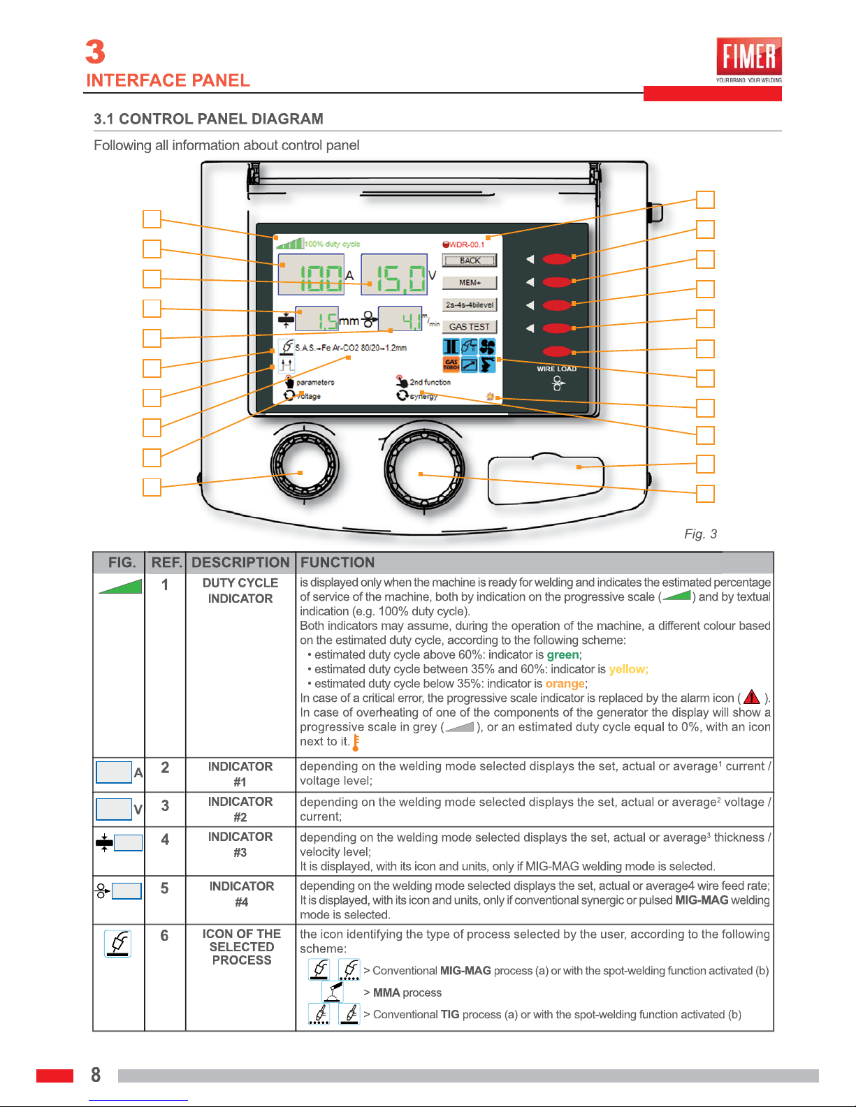
5
8
7
6
10
11
13
15
17
18
3
9
12
16
14
4

ENGLISH
25
26
27
30
19
21
20
22
23
24
28
29
1
2
3
4
5
6
7
8
9
10
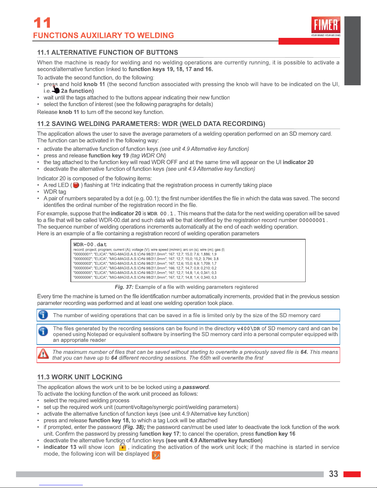
20
19
18
17
16
15
14
13
12
SD
11
ab
ab
ba b
ba b

ENGLISH
DSF
DUAL
PULSE
PULSE
ab
cd
ab
dcbad
ba
2a
function

a
b
b
a
ab
c

ENGLISH


ENGLISH
ABCD
EFGH

ABCD
Unscrew the ball-grip knob in the
centre of the spool support of the
welding wire.
If necessary, depending on the size of
the spool used, remove the bearing
spool.
Remove the plastic wrap from the
new spool and place the spool on the
appropriate support.
Replace the ball-grip knob.
EFGH
Unscrew the ball-grip knobs on the wirefeeding system and turn until the upper
wire feeder spools are raised.
Insert the wire into the inlet tube of
the wire feeder motor.
Run the wire under the wire feeder
spools all the way to the out-let of
the Euroconnector.
IL
Lower the upper spools and fasten the
plastic ball-grip knob of the wire tension
regulator.
Tighten the knob gently; if it is too
tight the wire could jam; if it is too
loose, it will be unable to feed the
wire, which will slip off. Repeat the
operation for the other knob.
CC
Please note that the hex socket (M8)
situated in the centre of the spool support is part of the wire tension system.
Tighten or loosen the hex socket
to set the correct tension: tightening too much can cause excessive tension that could prevent
the spool from turning correctly.
On the other hand, if the tension
is too loose, the welding wire
could accidentally unwind.

ENGLISH


ENGLISH


ENGLISH

Torch Trigger
Torch Trigger
T. T.
(a)
(b)
DSF

ENGLISH

DSF
bb

ENGLISH


ENGLISH


ENGLISH
Torch Trigger
Torch Trigger
(a)
(b)
Torch Trigger
T. T.
T. T.
Torch Trigger
(a)
(b)


ENGLISH
LEVEL-IBTRATS DOWNUP
P-START
BIT-REM
F (+5.1V)
C (HI-RIF)
COM-I (LO-RIF)
-SPOOL
+SPOOL
START
P-START
P-BI-LEV
P-DOWN
P-UP
COM(-)
REMOTE
REMOTE
TORCH
S3S3S1S1
E
DC
A
BGFE
DC
A
BG
F
A
B
C
D
E
F
G
E
A
B
D
C
E
A
B
D
C
C
B
A
D
E
1
2
3
4
5
S4S4
S6S6
H
1K
POT1
H
1K
POT1
1
3
2
S2S2


ENGLISH

ENGLISH

Sg2/Sg3
(7,85kg/dm3)
CrNi AiSi 308
(7,93kg/dm3)
CrNi AiSi 316
(7,98kg/dm3)
Al, AlMg, AlSi
(~2,70kg/dm3)
0,8mm 1,0mm 1,2mm 0,8mm 1,0mm 1,2mm 0,8mm 1,0mm 1,2mm 1,0mm 1,2mm
0,003946 0,006165 0,008878 0,003986 0,006228 0,008969 0,004011 0,006267 0,009025 0,002121 0,003054

ENGLISH


ENGLISH


ENGLISH


ENGLISH

ENGLISH


ENGLISH
5 4 3 2 1
D
C
B
A
A
2
1
2
1
2
1
2
1
J7 J7
+BUS
POT1
-BUS
POT1 POT2
+BUS -BUS
POT2
Modulo MD1 (PONTE/SCR)
--
+
+
1
TERRA
J6
4
2
Interruttore 2P 20A
Cod:001.399.005
3
1
J5
J8
J7
CLU/PUMP
CLU/FLUX
CN3
LINE-AUX
Sk Autom.MIG 3ph
cod::451.191.175
CN1
JP3
TL-PWR
24Vac
Fuse Cooling Unit
Pann. Poster.
NTC-MD1
Sk Aliment. MIG 3ph cod.:451.191.176
Cod.: 101.601.997
R1S1T1
JP17
+
SCHEDA POT1
SCHEDA POT2
CN22 CN23 CN22 CN23
CN17 CN18 CN17
CN7
CN8
CN14 CN14
CN15
CN15
CN4
Cavo Linea
RST
POT1
TRASD. TRASD.
POT2
++
JP6
JP8
Cod.:101.601.986
Cod.:101.601.986
Cod.: 101.601.842A
Cod.: 101.601.842B
Filtro RETE
LINE
LOAD
Cod.: 101.601.990
Cod.:101.601.994
Cod.: 101.601.992
1
++--
CN5
NOT ISOL. CAN
Cod.: 101.601.987 Cod.: 101.601.988
Cod.: 101.601.995
J10
+
-
++--
+
+DINSE(TIG)
FEED-S(MIG)
+-
-
Cod.: 101.601.1035
Cod.:101.601.1035
JP12
CN18
CN1
TRAFO-AUX
CN2
SIGNAL
Pannello POSTERIORE
JP14
+
-
+
JP15
Pann. FRONT. INFER.
+
-
+DINSE-
(MIG)
Cod.:101.601.991
Cod.: 101.601.993
FIN 3755.030.M
cod.: 090.000.034
cod.:001.800.013
Cod.:488.600.099
cod.:101.601.996
Cod.: 101.601.989
TF AUX
cod.:110.400.060
FAN-INV1 FAN-INV2
FAN MD1
Cod.: 101.601.1036
Cod: 101.601.1009
Cod.: 101.601.985
Cod.: 101.601.985
Cod: 101.601.1008
Cod: 101.601.1009
Cod: 101.601.1008
Pann. FRONT. SUPER.
SPIA Lumin.
SK Pot.451.191.181
SK Pot.451.191.181
LEM HAS400
Cod.:110.999.123
LEM HAS400
Cod.:110.999.123
Cod.:110.710.018
Cod.:110.710.018
Cod.049.446.020
Rosso + BUS
Nero - BUS
Rosso + BUS
Nero - BUS
Nero
Arancio
Arancio
Nero
0V
Nero
230V
Grigio
400V
Marrone
Bianco (0-24V)
Bianco (0-24V)
Giallo / Verde
Rosso (0-42V)
Rosso (0-42V)
Verde (FEED-S)
Verde (FEED-S)
Verde (FEED-S)
Nero
Giallo / Verde
Rosso (+DINSE)
Rosso (+DINSE)
Nero (-DINSE)
Nero
Arancio
Arancio
t
NTCtNTC
1
-
-
-
20
GIFAS +GIFAS +
12345
6
GIFAS -GIFAS -
1
2
12345
1
2
1
2
1
2
A
B
C
E
D
EDCBA
Can Bus Connector
A
B
C
E
D
EDCBA
Can Bus Connector
1
2
3
4
5
1
2
TELERUTTORETELERUTTORE
A1
1L1
3L2
5L3 6T3
4T2
2T1
A2
12345
1
2
MV
-
+
MV
-
+
E
DC
A
BG
F
E
DC
A
BG
F
ABCDEFG
GIFAS OUT+GIFAS OUT+
E
D
C
A
B
EDCBA
Cooling Unit
E
D
C
A
B
EDCBA
Cooling Unit
1
2
3
4
5
1
2
1
2
GIFAS OUT-GIFAS OUT-
1
2
ABCDEFGHJLMNP
Q
RSTUV
K
KAB
J
T
L
MC
SVUN
HRQPD
GFE
ABCDEFGHJLMNP
Q
RSTUV
K
KAB
J
T
L
MC
SVUN
HRQPD
GFE
123456789
1011121314
15
16
17
18
19
20
1
2
1
2
MV
-
+
FAN 24V cod.:019.501.167
MV
-
+
FAN 24V cod.:019.501.167
MV
+
-
cod.:019.501.164
FAN DC 12V 3W
MV
+
-
cod.:019.501.164
FAN DC 12V 3W
0
230V
24V
0
0
42V
400V
KRONOS 500

5 4 3 2 1
D
C
B
A
A
PANNELLINO POSTERIORE
Cod.: 101.601.1000
Cod.: 101.601.1001
Cod.: 101.601.1002
Conn. SIGNAL
CN12
CN13
J4 J1 J3 J7
Encoder
Cod.: 101.601.1003
CN5
CN1
M
+
-
CN3
Conn. REMOTE
GAS OUT TIG
Tubo GAS TIG
Tubo GAS MIG
CN11
J9 J10
Sk Display cod.: 451.191.164
Sk CTRL Mot. cod.:
451.191.094
PANNELLINO FRONTALE
RemoteTorch
Int Non Isolated
CAN Port
Cod.: 101.601.998
Cod.: 101.601.999
Cod.: 280.024.007A
GAS OUT
MIG
Staffa
rame
Tubo GAS MIG
Tubo GAS TIG
Tubo GAS TIG
Tubo GAS MIG
Tubo GAS MIG
Cod.: 101.601.998
GAS IN
Elettrov. MIG
Elettrov. TIG
Cod.: 280.024.007A
0 - 42V
Encoder Motore Comandi Motore
SPOOL- SPOOL+ MOT+ MOT-
1
11
11
11
CN4
+24Vdc
EV MIG
EV TIG
Cod.: 101.601.1006
RC1 RC2
Cod.: 101.601.1007
P-UP
Rosso (0V)
Rosso (0V)
Rosso (42V)
Verde (FEED-S)
P-BI_LEV
P-DOWN
P-START
COM(-)
COMCF
Rosso
Rosso (42V)
Verde
Nero (Spool-)
Rosso (Spool+)
Blu
Blu
Verde (FEED-S)
Verde (FEED-S)
Verde (FEED-S)
Grigio
Grigio
Blu
Gia./Ver. (terra)
Gia./Ver. (terra)
BIT-REM
P-START
Blu
Blu
EV TIG
EV TIG
EV MIG
EV MIG
+24Vdc
+24Vdc
+24Vdc
GIFAS OUTGIFAS OUT
1234567
1
2
3
4
5
6
7
12345
6
12345
1
2
3
4
NCNC
1
2
GIFAS OUT+GIFAS OUT+
E
A
B
D
C
EDC
B
A
Conn. CANBUS
E
A
B
D
C
EDC
B
A
Conn. CANBUS
1
2
3
4
5
E
DC
A
BG
F
E
DC
A
BG
F
ABCDEFG
E
A
B
D
C
ABCDE
Conn. TORCH
E
A
B
D
C
ABCDE
Conn. TORCH
NCNC
1
2
123
1234567
E
DC
A
BG
FEDC
A
BG
F
ABCDEFG
WIRE FEEDER

ENGLISH

+39-039-6079326
Via J.F. Kennedy - 20871 Vimercate (MB) Italy
Phone: +39 039 98981
| Fax +39 039 6079334
www.fimer.com | info@fimer.com
ASSISTANCE
FAX +39-039-6079334
Technical Assistance:
service.welding@fimer.com
Monday To Friday
09.00 / 12.30
15.30 / 17.00
 Loading...