

Page 1

Cisco Reader Comment Card
General Information
1 Years of networking experience: Years of experience with Cisco products:
2 I have these network types: LAN Backbone WAN
Other:
3 I have these Cisco products: Switches Routers
Other (specify models):
4 I perform these types of tasks: H/W installation and/or maintenance S/W configuration
Network management Other:
5 I use these types of documentation: H/W installation H/W configuration S/W configuration
Command reference Quick reference Release notes Online help
Other:
6 I access this information through: Cisco.com (CCO) CD-ROM
7 I prefer this access method:
8 I use the following three product features the most:
Printed docs Other:
% %
% %
Document Information
Document Title: Cisco 6130 with NI-2 Hardware Installation Guide
Part Number: OL-3768-01 S/W Release (if applicable):
On a scale of 1–5 (5 being the best), please let us know how we rate in the following areas:
The document is written at my technical
The information is accurate.
level of understanding.
The document is complete. The information I wanted was easy to find.
The information is well organized. The information I found was useful to my job.
Please comment on our lowest scores:
Mailing Information
Company Name Date
Contact Name Job Title
Mailing Address
City State/Province ZIP/Postal Code
Country Phone ( ) Extension
Fax ( ) E-mail
Can we contact you further concerning our documentation? Yes No
You can also send us your comments by e-mail to [email protected], or by fax to 408-527-8089.
Page 2

BUSINESS REPLY MAIL
FIRST-CLASS MAIL PERMIT NO. 4631 SAN JOSE CA
ATTN DOCUMENT RESOURCE CONNECTION
CISCO SYSTEMS INC
170 WEST TASMAN DRIVE
SAN JOSE CA 95134-9883
POSTAGE WILL BE PAID BY ADDRESSEE
UNITED STATES
IN THE
NO POSTAGE
NECESSARY
IF MAILED
Page 3

Cisco 6130 with NI-2 Hardware Installation Guide
Corporate Headquarters
Cisco Systems, Inc.
170 West Tasman Drive
San Jose, CA 95134-1706
USA
http://www.cisco.com
Tel: 408 526-4000
800 553-NETS (6387)
Fax: 408 526-4100
Text Part Number: OL-3768-01
Page 4

THE SPECIFICATIONS AND INFORMATION REGARDING THE PRODUCTS IN THIS MANUAL ARE SUBJECT TO CHANGE WITHOUT NOTICE. ALL
STATEMENTS, INFORMATION, AND RECOMMENDATIONS IN THIS MANUAL ARE BELIEVED TO BE ACCURATE BUT ARE PRESENTED WITHOUT
WARRANTY OF ANY KIND, EXPRESS OR IMPLIED. USERS MUST TAKE FULL RESPONSIBILITY FOR THEIR APPLICATION OF ANY PRODUCTS.
THE SOFTWARE LICENSE AND LIMITED WARRANTY FOR THE ACCOMPANYING PRODUCT ARE SET FORTH IN THE INFORMATION PACKET THAT
SHIPPED WITH THE PRODUCT AND ARE INCORPORATED HEREIN BY THIS REFERENCE. IF YOU ARE UNABLE TO LOCATE THE SOFTWARE LICENSE
OR LIMITED WARRANTY, CONTACT YOUR CISCO REPRESENTATIVE FOR A COPY.
The following information is for FCC compliance of Class A devices: This equipment has been tested and found to comply with the limits for a Class A digital device, pursuant
to part 15 of the FCC rules. These limits are designed to provide reasonable protection against harmful interference when the equipment is operated in a commercial
environment. This equipment generates, uses, and can radiate radio-frequency energy and, if not installed and used in accordance with the instruction manual, may cause
harmful interference to radio communications. Operation of this equipment in a residential area is likely to cause harmful interference, in which case users will be required
to correct the interference at their own expense.
The following information is for FCC compliance of Class B devices: The equipment described in this manual generates and may radiate radio-frequency energy. If it is not
installed in accordance with Cisco’s installation instructions, it may cause interference with radio and television reception. This equipment has been tested and found to
comply with the limits for a Class B digital device in accordance with the specifications in part 15 of the FCC rules. These specifications are designed to provide reasonable
protection against such interference in a residential installation. However, there is no guarantee that interference will not occur in a particular installation.
Modifying the equipment without Cisco’s written authorization may result in the equipment no longer complying with FCC requirements for Class A or Class B digital
devices. In that event, your right to use the equipment may be limited by FCC regulations, and you may be required to correct any interference to radio or television
communications at your own expense.
You can determine whether your equipment is causing interference by turning it off. If the interference stops, it was probably caused by the Cisco equipment or one of its
peripheral devices. If the equipment causes interference to radio or television reception, try to correct the interference by using one or more of the following measures:
• Turn the television or radio antenna until the interference stops.
• Move the equipment to one side or the other of the television or radio.
• Move the equipment farther away from the television or radio.
• Plug the equipment into an outlet that is on a different circuit from the television or radio. (That is, make certain the equipment and the television or radio are on circuits
controlled by different circuit breakers or fuses.)
Modifications to this product not authorized by Cisco Systems, Inc. could void the FCC approval and negate your authority to operate the product.
The Cisco implementation of TCP header compression is an adaptation of a program developed by the University of California, Berkeley (UCB) as part of UCB’s public
domain version of the UNIX operating system. All rights reserved. Copyright © 1981, Regents of the University of California.
NOTWITHSTANDING ANY OTHER WARRANTY HEREIN, ALL DOCUMENT FILES AND SOFTWARE OF THESE SUPPLIERS ARE PROVIDED “AS IS” WITH
ALL FAULTS. CISCO AND THE ABOVE-NAMED SUPPLIERS DISCLAIM ALL WARRANTIES, EXPRESSED OR IMPLIED, INCLUDING, WITHOUT
LIMITATION, THOSE OF MERCHANTABILITY, FITNESS FOR A PARTICULAR PURPOSE AND NONINFRINGEMENT OR ARISING FROM A COURSE OF
DEALING, USAGE, OR TRADE PRACTICE.
IN NO EVENT SHALL CISCO OR ITS SUPPLIERS BE LIABLE FOR ANY INDIRECT, SPECIAL, CONSEQUENTIAL, OR INCIDENTAL DAMAGES, INCLUDING,
WITHOUT LIMITATION, LOST PROFITS OR LOSS OR DAMAGE TO DATA ARISING OUT OF THE USE OR INABILITY TO USE THIS MANUAL, EVEN IF CISCO
OR ITS SUPPLIERS HAVE BEEN ADVISED OF THE POSSIBILITY OF SUCH DAMAGES.
CCIP, the Cisco Arrow logo, the Cisco Powered Network mark, the Cisco Systems Verified logo, Cisco Unity, Follow Me Browsing, FormShare, iQ Breakthrough, iQ
Expertise, iQ FastTrack, the iQ Logo, iQ Net Readiness Scorecard, Networking Academy, ScriptShare, SMARTnet, TransPath, and Voice LAN are trademarks of Cisco
Systems, Inc.; Changing the Way We Work, Live, Play, and Learn, Discover All That’s Possible, The Fastest Way to Increase Your Internet Quotient, and iQuick Study are
service marks of Cisco Systems, Inc.; and Aironet, ASIST, BPX, Catalyst, CCDA, CCDP, CCIE, CCNA, CCNP, Cisco, the Cisco Certified Internetwork Expert logo, Cisco
IOS, the Cisco IOS logo, Cisco Press, Cisco Systems, Cisco Systems Capital, the Cisco Systems logo, Empowering the Internet Generation, Enterprise/Solver, EtherChannel,
EtherSwitch, Fast Step, GigaStack, Internet Quotient, IOS, IP/TV, LightStream, MGX, MICA, the Networkers logo, Network Registrar, Packet, PIX, Post-Routing,
Pre-Routing, RateMUX, Registrar, SlideCast, StrataView Plus, Stratm, SwitchProbe, TeleRouter, and VCO are registered trademarks of Cisco Systems, Inc. and/or its
affiliates in the U.S. and certain other countries.
All other trademarks mentioned in this document or Web site are the property of their respective owners. The use of the word partner does not imply a partnership relationship
between Cisco and any other company. (0208R)
Cisco 6130 with NI-2 Hardware Installation Guide
Copyright © 2003, Cisco Systems, Inc.
All rights reserved.
Page 5

Preface xvii
Audience xvii
Purpose xvii
Organization xvii
Conventions xviii
Related Documentation xix
Obtaining Documentation xix
World Wide Web xix
Documentation CD-ROM xx
Ordering Documentation xx
Documentation Feedback xx
Obtaining Technical Assistance xx
Cisco.com xxi
Technical Assistance Center xxi
Contacting TAC by Using the Cisco TAC Website xxi
Contacting TAC by Telephone xxi
CONTENTS
CHAPTER
1 Product Overview 1-1
Introduction to the Cisco 6130 with NI-2 System 1-1
Features 1-2
Configurations 1-2
Cisco 6130 with a POTS Splitter Configuration 1-3
Cisco 6130 Without a POTS Splitter Configuration 1-4
Subtended Network Configuration 1-5
Cisco 6130 Chassis Overview 1-8
Cisco 6130 Card Compartment 1-9
Cisco 6130 Backplane 1-10
Cisco 6130 Cards 1-12
4xDMT Overview 1-13
4xflexi Overview 1-15
4xSDSL Overview 1-18
DS3/2DS3 NI-2 Card Overview 1-20
OC-3c/OC-3c NI-2 Card Overview 1-23
Network Clocking Overview 1-26
OL-3768-01
Cisco 6130 with NI-2 Hardware Installation Guide
iii
Page 6

Contents
Redundancy Overview 1-26
System I/O Card 1-28
Front Cover 1-32
Rear Cover 1-32
Fan Tray 1-33
Cisco 6120 POTS Splitter Overview 1-34
Cisco 6120 Card Compartment 1-34
Cisco 6120 Backplane 1-35
Cisco 6120 Cards 1-37
Management Software 1-37
CHAPTER
2 Preparing for Installation 2-1
Safety Requirements 2-1
Safety Guidelines 2-1
Maintaining Safety with Electricity 2-8
Preventing Electrostatic Discharge Damage 2-9
General Maintenance Guidelines 2-9
Hot Swapping Cards 2-10
Installation and Replacement Suggestions 2-10
Site Requirements 2-10
Environmental Requirements 2-11
Temperature, Altitude, and Humidity 2-11
Ventilation 2-11
Space 2-12
Power 2-13
Cables 2-14
Rack-Mounting 2-14
Required Tools and Equipment 2-15
Unpacking the Cisco 6130 System 2-17
CHAPTER
iv
Verifying Contents 2-17
Inspecting for Damage 2-18
3 Installing a Cisco 6130 with a POTS Splitter Configuration 3-1
Installation Checklist 3-1
Installation Procedures 3-2
Stabilize and Measure Rack Space 3-3
Install the POTS Splitter 3-4
Install the Cisco 6120 3-4
Cisco 6130 with NI-2 Hardware Installation Guide
OL-3768-01
Page 7

Install the Third-Party POTS Splitter 3-5
Install the Fan Tray 3-5
Install the Cisco 6130 Chassis 3-7
Install Blank Faceplates 3-7
Ground the Cisco 6130, Fan Tray, and POTS Splitter 3-7
Connect the Cisco 6130 Chassis to the POTS Splitter 3-9
Connect the Cisco 6130 to the Cisco 6120 3-9
Connect the Cisco 6130 to the Third-Party POTS Splitter 3-11
Attach Cisco 6130 Power Connections 3-11
Attach Cisco 6130 Power Connections for a Dual-Power Feed 3-12
Attach Cisco 6130 Power Connections for a Single-Power Feed 3-15
Attach Fan Tray Power Connections 3-17
Attach Fan Tray Power Connections for a Dual-Power Feed 3-18
Attach Fan Tray Power Connections for a Single-Power Feed 3-19
Locate or Install the System I/O Card 3-20
Connect the Fan Tray 3-26
Connect the Alarm Contacts 3-26
Connect the POTS Splitter to the MDF 3-28
Connect the Cisco 6120 to the MDF 3-28
Connect the Third-Party POTS Splitter to the MDF 3-29
Pull Away All Line Cards 3-30
Install the Rear Cover 3-30
Apply Power 3-33
Verify Fan Tray Operation 3-33
Install the NI-2 Card(s) 3-34
Reseat the Line Cards 3-36
Install the Line Cards in the Cisco 6130 and POTS Splitter 3-36
Connect the NI-2 Card to the Network 3-38
DS3 Network Connection Installation 3-38
OC-3c/OC-3c Network Connection Installation 3-40
Install a Subtended Network Configuration 3-42
Cable the DS3 Subtending Network Configuration 3-42
Cable the OC-3c Subtending Network Configuration 3-44
Connect the Ethernet to the Management Network 3-46
Connect a Console Terminal 3-47
Connect the Auxiliary Port 3-47
Close the Cisco 6130 Front Cover 3-48
Close the Rear Cover 3-48
Complete Initial Configuration 3-50
Before You Begin 3-51
Contents
OL-3768-01
Cisco 6130 with NI-2 Hardware Installation Guide
v
Page 8

Contents
Using the System Configuration Dialog 3-51
CHAPTER
4 Installing a Cisco 6130 Without a POTS Splitter Configuration 4-1
Installation Checklist 4-1
Installation Procedures 4-2
Stabilize and Measure Rack Space 4-3
Install the Fan Tray 4-3
Install the Cisco 6130 Chassis 4-5
Install Blank Faceplates 4-5
Ground the Cisco 6130 Chassis and Fan Tray 4-6
Connect the Cisco 6130 to the MDF 4-7
Attach Cisco 6130 Power Connections 4-7
Attach Cisco 6130 Power Connections for a Dual-Power Feed 4-9
Attach Cisco 6130 Power Connections for a Single-Power Feed 4-11
Attach Fan Tray Power Connections 4-13
Attach Fan Tray Power Connections for a Dual-Power Feed 4-14
Attach Fan Tray Power Connections for a Single-Power Feed 4-15
Locate or Install the System I/O Card 4-17
Connect the Fan Tray 4-22
Connect the Alarm Contacts 4-22
Pull Away All Line Cards 4-24
Install the Rear Cover 4-25
Apply Power 4-28
Verify Fan Tray Operation 4-28
Install the NI-2 Card(s) 4-29
Reseat the Line Cards 4-31
Install the Line Cards in the Cisco 6130 4-31
Connect the NI-2 Card to the Network 4-33
DS3 Network Connection Installation 4-33
OC-3c Network Connection Installation 4-35
Install a Subtended Network Configuration 4-37
Cable the DS3 Subtending Network Configuration 4-37
Cable the OC-3c Subtending Network Configuration 4-39
Connect the Ethernet to the Management Network 4-41
Connect a Console Terminal 4-42
Connect the Auxiliary Port 4-42
Close the Cisco 6130 Front Cover 4-43
Close the Rear Cover 4-43
Complete Initial Configuration 4-45
vi
Cisco 6130 with NI-2 Hardware Installation Guide
OL-3768-01
Page 9

Before You Begin 4-46
Using the System Configuration Dialog 4-46
Contents
CHAPTER
CHAPTER
5 Troubleshooting 5-1
Hot-Swappable FRUs 5-2
Basic Checks 5-2
Contacting the Cisco TAC for Help 5-3
System-Wide Problems 5-3
Cisco 6130 Component-Specific Problems 5-6
NI-2 Card Problems 5-6
NI-2 Card Cold Redundancy Problems 5-7
Line Card Problems 5-8
System I/O Card Problems 5-11
Fan Tray Problems 5-13
Alarms 5-13
6 Upgrading and Maintaining the Cisco 6130 System 6-1
Backing Up Software 6-1
Fan Tray Maintenance 6-2
Replacing the Air Filter in the Fan Tray 6-2
Replacing Fans in the Fan Tray 6-4
Installing and Replacing Hardware 6-6
xTU-C Line Card Installation and Removal 6-6
Installing an xTU-C Line Card 6-6
Removing an xTU-C Line Card 6-8
Blank Faceplate Installation and Removal 6-8
Installing a Blank Faceplate 6-8
Removing a Blank Faceplate 6-9
DS3/2DS3 NI-2 Card Installation and Removal 6-9
Installing a DS3/2DS3 NI-2 Card 6-10
Removing a DS3/2DS3 NI-2 Card 6-12
OC-3c/OC-3c NI-2 Card Installation and Removal 6-13
Installing an OC-3c/OC-3c NI-2 Card 6-14
Removing an OC-3c/OC-3c NI-2 Card 6-16
System I/O Card Installation and Removal 6-17
Installing a System I/O Card 6-17
Removing a System I/O Card 6-24
OL-3768-01
Cisco 6130 with NI-2 Hardware Installation Guide
vii
Page 10

Contents
CHAPTER
APPENDIX
APPENDIX
7 Testing Configuration Connections for the Cisco 6130 with NI-2 System 7-1
Required Equipment 7-1
Testing System Connectivity 7-2
Testing PPP Connectivity 7-3
A Technical Specifications A-1
Hardware Specifications A-1
Cisco 6130 with NI-2 System Specifications A-2
4xDMT Specifications A-3
4xflexi Specifications A-3
4xSDSL Specifications A-4
DS3/2DS3 NI-2 Card Specifications A-5
OC-3c/OC-3c NI-2 Card Specifications A-6
Software Specifications A-7
B Cable and Port Mapping Specifications B-1
Cabling Guidelines B-2
Cisco 6130 with a POTS Splitter Configuration Cables B-3
Cisco 6130 to Cisco 6120 Cables B-3
Cisco 6130 to Third-Party POTS Splitter Cables B-5
POTS Splitter to MDF Cables B-7
One-to-One Cables B-7
Two-to-Two Cables B-8
APPENDIX
viii
Cisco 6130 Without a POTS Splitter Configuration Cables B-10
Intermixing Cables B-12
Port Mapping Tables B-13
Cisco 6130 with a POTS Splitter Configuration Port Mapping Tables B-13
Cisco 6130 Without a POTS Splitter Configuration Port Mapping Tables B-26
Port Mapping Table for Building Cisco 6130 Cables B-31
Standard Telco Color Chart B-37
C Connector and Pinout Specifications C-1
Cisco 6130 Chassis Connectors C-1
xDSL Connectors C-1
Cisco 6130 Terminal Block Connector C-2
Cisco 6120 Chassis Connectors C-2
Console and Auxiliary Ports C-3
Cisco 6130 with NI-2 Hardware Installation Guide
OL-3768-01
Page 11

G
LOSSARY
I
NDEX
Contents
Ethernet Port C-4
OL-3768-01
Cisco 6130 with NI-2 Hardware Installation Guide
ix
Page 12

Contents
Cisco 6130 with NI-2 Hardware Installation Guide
x
OL-3768-01
Page 13

Figure 1-1 Cisco 6130 with a POTS Splitter Configuration 1-3
Figure 1-2 Cisco 6130 Without a POTS Splitter Configuration 1-5
Figure 1-3 Subtended Network Configuration Using DS3/2DS3 NI-2 Cards 1-7
Figure 1-4 Subtended Network Configuration Using OC-3c/OC-3c NI-2 Cards 1-8
Figure 1-5 Cisco 6130 Card Slots 1-10
Figure 1-6 Cisco 6130 Backplane 1-11
Figure 1-7 4xDMT Faceplate 1-14
Figure 1-8 Edge Connector Key 1-16
Figure 1-9 4xflexi Faceplate 1-17
Figure 1-10 4xSDSL Faceplate 1-19
Figure 1-11 DS3/2DS3 NI-2 Card Faceplate 1-21
Figure 1-12 OC-3c/OC-3c NI-2 Card Faceplate 1-24
Figure 1-13 System I/O Card Locations 1-28
Figure 1-14 System I/O Card 1-29
Figure 1-15 Cisco 6130 Front Cover Installation 1-32
FIGURES
Figure 1-16 Fan Tray 1-33
Figure 1-17 Fan Tray Backplane 1-33
Figure 1-18 Cisco 6120 Card Slots 1-35
Figure 1-19 Cisco 6120 Backplane 1-35
Figure 1-20 Cisco 6120 Connections 1-36
Figure 1-21 DMT POTS Card Faceplate 1-37
Figure 3-1 Fan Tray Thumbscrews 3-5
Figure 3-2 Removing the Fan Module from the Fan Tray 3-6
Figure 3-3 Grounding the Cisco 6130, Fan Tray, and POTS Splitter 3-9
Figure 3-4 Cisco 6130 to Two Cisco 6120 Chassis Cabling Diagram with One-to-Two Cables 3-10
Figure 3-5 Cisco 6130 Power Connection Locations 3-12
Figure 3-6 Power Input Connections for the Cisco 6130—Dual-Power Feed 3-13
Figure 3-7 Wire Looped through Ferrite 3-13
Figure 3-8 Power Return Connections for the Cisco 6130—Dual-Power Feed 3-14
Figure 3-9 Power Connections for the Cisco 6130—Single-Power Feed 3-15
Figure 3-10 Wire Looped through Ferrite 3-16
OL-3768-01
Cisco 6130 with NI-2 Hardware Installation Guide
xi
Page 14

Figures
Figure 3-11 Fan Tray Power Connection Location 3-17
Figure 3-12 Power Connections for the Fan Tray—Dual-Power Feed 3-18
Figure 3-13 Power Connections for the Fan Tray—Single-Power Feed 3-19
Figure 3-14 Backplane Screw Location for System I/O Card Installation 3-21
Figure 3-15 Standoff Screw Location for System I/O Card Installation 3-22
Figure 3-16 System I/O Card Installation 3-23
Figure 3-17 EMI Cover Installation 3-24
Figure 3-18 Safety Shield and ESD Shield Installation 3-25
Figure 3-19 Cabling the Fan Tray to the Cisco 6130 Backplane 3-26
Figure 3-20 System I/O Card Alarm Contacts 3-27
Figure 3-21 Cisco 6120 Connection to the MDF 3-29
Figure 3-22 Unlocking the Line Card 3-30
Figure 3-23 Backplane Screws for Rear Cover Installation 3-31
Figure 3-24 Installing the Cover-Mounting Bracket 3-32
Figure 3-25 NI-2 Card Installation 3-35
Figure 3-26 Locking the NI-2 Card 3-35
Figure 3-27 DS3 Network Interface Connection 3-39
Figure 3-28 OC-3c Network Interface Connection 3-41
Figure 3-29 Cabling for DS3 Subtending Configuration 3-43
Figure 3-30 Cabling Diagram for OC-3c Subtending 3-45
Figure 3-31 ENET, CNSL, and AUX RJ-45C Receptacles on the NI-2 Card 3-46
Figure 3-32 Cisco 6130 Front Cover Installation 3-48
Figure 3-33 Securing the Rear Cover with the Latches 3-49
Figure 3-34 Securing the Rear Cover with Two Thumbscrews 3-50
Figure 4-1 Fan Tray Thumbscrews 4-4
Figure 4-2 Removing the Fan Module from the Fan Tray 4-4
Figure 4-3 Grounding the Cisco 6130 and Fan Tray 4-7
Figure 4-4 Cisco 6130 Power Connection Locations 4-8
Figure 4-5 Power Input Connections for the Cisco 6130—Dual-Power Feed 4-9
Figure 4-6 Wire Looped through Ferrite 4-10
Figure 4-7 Power Return Connections for the Cisco 6130—Dual-Power Feed 4-10
Figure 4-8 Power Connections for the Cisco 6130—Single-Power Feed 4-12
Figure 4-9 Wire Looped through Ferrite 4-12
Figure 4-10 Fan Tray Power Connection Location 4-13
Figure 4-11 Power Connections for the Fan Tray—Dual-Power Feed 4-14
Cisco 6130 with NI-2 Hardware Installation Guide
xii
OL-3768-01
Page 15

Figure 4-12 Power Connections for the Fan Tray—Single-Power Feed 4-16
Figure 4-13 Backplane Screw Location for System I/O Card Installation 4-17
Figure 4-14 Standoff Screw Location for System I/O Card Installation 4-18
Figure 4-15 System I/O Card Installation 4-19
Figure 4-16 EMI Cover Installation 4-20
Figure 4-17 Safety Shield and ESD Shield Installation 4-21
Figure 4-18 Cabling the Fan Tray to the Cisco 6130 Backplane 4-22
Figure 4-19 System I/O Card Alarm Contacts 4-23
Figure 4-20 Unlocking the Line Card 4-25
Figure 4-21 Backplane Screws for Rear Cover Installation 4-26
Figure 4-22 Installing the Cover-Mounting Bracket 4-27
Figure 4-23 NI-2 Card Installation 4-30
Figure 4-24 Locking the NI-2 Card 4-30
Figures
Figure 4-25 DS3 Network Interface Connection 4-34
Figure 4-26 OC-3c Network Interface Connection 4-36
Figure 4-27 Cabling for DS3 Subtending Configuration 4-38
Figure 4-28 Cabling Diagram for OC-3c Subtending 4-40
Figure 4-29 ENET, CNSL, and AUX RJ-45C Receptacles on the NI-2 Card 4-41
Figure 4-30 Cisco 6130 Front Cover Installation 4-43
Figure 4-31 Securing the Rear Cover with the Latches 4-44
Figure 4-32 Securing the Rear Cover with Two Thumbscrews 4-45
Figure 6-1 Location of Air Filter Thumbscrews 6-2
Figure 6-2 Removing Air Filter Door and Dirty Air Filter 6-3
Figure 6-3 Installing the Replacement Air Filter 6-4
Figure 6-4 Location of Fan Tray Thumbscrews 6-5
Figure 6-5 Removing the Fan Module from the Fan Tray 6-5
Figure 6-6 xTU-C Line Card Installation 6-7
Figure 6-7 Positioning the Locking Tab for the xTU-C Line Card Installation and Removal 6-7
Figure 6-8 NI-2 Card Installation 6-10
Figure 6-9 Locking the NI-2 Card 6-11
Figure 6-10 ENET, CNSL, and AUX RJ-45C Receptacles on the NI-2 Card 6-12
Figure 6-11 OC-3c Network Interface Connection 6-15
Figure 6-12 Backplane Screw Location for System I/O Card Installation 6-17
Figure 6-13 Standoff Screw Location for System I/O Card Installation 6-18
Figure 6-14 System I/O Card Installation 6-19
Cisco 6130 with NI-2 Hardware Installation Guide
OL-3768-01
xiii
Page 16

Figures
Figure 6-15 EMI Cover Installation 6-20
Figure 6-16 Safety Shield and ESD Shield Installation 6-21
Figure 6-17 Cabling for DS3 Subtending Configuration 6-23
Figure 6-18 EMI Cover Removal 6-25
Figure 6-19 Safety Shield and ESD Shield Removal 6-26
Figure 6-20 System I/O Card Removal 6-27
Figure B-1 Cabling Guidelines B-2
Figure B-2 One-to-Two Cable B-4
Figure B-3 Cisco 6130 to Two Cisco 6120 Chassis Cabling Diagram with One-to-Two Cables B-5
Figure B-4 One-to-One Special Cable B-6
Figure B-5 One-to-One Cable B-8
Figure B-6 Cisco 6120 to MDF Cabling Diagram with One-to-One Cables B-8
Figure B-7 Cisco 6120 to POTS Service Cabling Diagram with One-to-One Cables B-8
Figure B-8 Two-to-Two Cable B-9
Figure B-9 Cisco 6120 to MDF Cabling Diagram with Two-to-Two Cables—xDSL Subscriber Line Connectors B-10
Figure B-10 Cisco 6120 to MDF Cabling Diagram with Two-to-Two Cables—Voice Line Connectors B-10
Figure B-11 Three-to-Three Cable B-11
Figure B-12 Cisco 6130 to MDF Cabling Diagram with Three-to-Three Cables B-12
Figure C-1 xDSL Connector Pin Locations C-1
Figure C-2 Cisco 6130 Power Terminal Block C-2
Figure C-3 Connector Pin Locations for All Champ Connectors C-2
Figure C-4 NI-2 Card Console and Auxiliary Receptacle C-3
Figure C-5 NI-2 Card Management Ethernet Receptacle C-4
xiv
Cisco 6130 with NI-2 Hardware Installation Guide
OL-3768-01
Page 17

Table 1 Font Conventions xviii
Table 2 Command Syntax Conventions xviii
Table 1-1 Cisco 6130 Card Slot Assignments 1-9
Table 1-2 Cisco 6130 Backplane Connectors and Switches 1-11
Table 1-3 Cisco 6130 Card and Configuration Compatibility 1-12
Table 1-4 4xDMT LED Indicators 1-14
Table 1-5 4xflexi LED Indicators 1-17
Table 1-6 4xSDSL LED Indicators 1-19
Table 1-7 Interface Status LED Group Indicators 1-22
Table 1-8 Alarm Status LED Group Indicators 1-22
Table 1-9 ENET Interface LED Indicators 1-23
Table 1-1 0 OC-3c/OC-3c NI-2 Card LED Group Indicators 1-25
Table 1-1 1 System I/O Card Connectors and Headers 1-29
Table 1-1 2 Fan Tray Backplane Connectors 1-33
Table 1-1 3 Cisco 6120 Card Slot Assignments 1-34
TABLES
Table 1-1 4 Cisco 6120 Backplane Connectors 1-35
Table 2-1 CO Operating Environment Requirements 2-11
Table 2-2 Rack Space Requirements 2-12
Table 2-3 Rack Space Calculation for the Cisco 6130 with NI-2 System Configurations 2-12
Table 2-4 Fuse Calculation for the Cisco 6130 with NI-2 System Components 2-13
Table 2-5 Tool and Equipment Requirements Checklist 2-15
Table 3-1 Installation Checklist—Cisco 6130 Chassis with a POTS Splitter Configuration 3-2
Table 3-2 Cisco 6130 and Cisco 6120 Corresponding Connectors 3-10
Table 3-3 System I/O Card Wire-Wrap Pin Mapping 3-28
Table 3-4 Terminal Settings 3-47
Table 4-1 Installation Checklist—Cisco 6130 Chassis without a POTS Splitter Configuration 4-2
Table 4-2 System I/O Card Wire-Wrap Pin Mapping 4-24
Table 4-3 Terminal Settings 4-42
Table 5-1 Service Interruptions Caused by the Replacing of FRUs 5-2
Table 5-2 Chassis Alarm 5-13
Table 5-3 Line Card Slot Alarms 5-14
OL-3768-01
Cisco 6130 with NI-2 Hardware Installation Guide
xv
Page 18

Tables
Table 5-4 NI-2 Redundancy Alarms 5-14
Table 5-5 IOS Controller Alarms 5-14
Table 5-6 OC-3c/STM-1 Network Interface Alarms 5-15
Table 5-7 DS3/E3 Network Interface Alarms 5-16
Table 5-8 Fan Tray Alarms 5-16
Table 6-1 Terminal Settings 6-12
Table 7-1 Bit Field Description 7-2
Table A-1 Hardware Specifications A-2
Table A-2 4xDMT Specifications A-3
Table A-3 4xflexi Specifications A-3
Table A-4 4xSDSL Specifications A-4
Table A-5 DS3/2DS3 NI-2 Card Specifications A-5
Table A-6 OC-3c/OC-3c NI-2 Card Specifications A-6
Table A-7 Software Specifications A-7
Table B-1 Cisco 6130 with NI-2 System Configuration and Cable Overview B-1
Table B-2 Connectors and Part Numbers for One-to-Two Cables—Cisco 6130 to Two Cisco 6120
Chassis Connection
B-3
Table B-3 Connectors and Part Numbers for One-to-One Cables for the Third-Party POTS Splitter B-6
Table B-4 Connectors, Lengths, and Part Numbers for One-to-One Cables—Cisco 6120 to MDF or POTS
Connections
B-7
Table B-5 Connectors and Part Numbers for Two-to-Two Cables—Cisco 6120 to
MDF Connections
B-9
Table B-6 Connectors and Part Numbers for Three-to-Three Cables—Cisco 6130 to MDF Connections B-11
Table B-7 Connectors and Part Numbers for CAB-128-Mix Cable Set B-12
Table B-8 Port Mapping for One-to-Two Cables in a Cisco 6130 with a POTS
Splitter Configuration
B-14
Table B-9 Port Mapping for One-to-One Cables with a Third-Party POTS Splitter B-18
Table B-1 0 Port Mapping for Two-to-Two Cables in a Cisco 6130 with a POTS
Splitter Configuration
B-23
Table B-1 1 Port Mapping for Three-to-Three Cables in a Cisco 6130 Without a POTS Splitter Configuration B-26
Table B-1 2 Port Mapping for Building Cisco 6130 Cables B-31
Table B-1 3 Standard Telco Color Chart B-37
Table C-1 Pin Assignments for the NI-2 Card Console and Auxiliary Receptacles C-3
Table C-2 Pin Assignments for the NI-2 Card Management Ethernet Receptacle C-4
Cisco 6130 with NI-2 Hardware Installation Guide
xvi
OL-3768-01
Page 19

Audience
Purpose
Preface
This preface explains the audience, purpose, and organization of the Cisco 6130 with NI-2 Hardware
Installation Guide. It also defines the conventions that are used to present instructions and information.
The Cisco 6130 with NI-2 Hardware Installation Guide is intended for use by central office
(CO) technicians and maintenance personnel who are responsible for installing, configuring, and
maintaining the Cisco 6130 with NI-2 system. A familiarity with telco products and networking systems
is recommended.
The Cisco 6130 with NI-2 Hardware Installation Guide describes how to set up, install, and troubleshoot
the Cisco 6130 with NI-2 system. After completing the installation procedures covered in this guide,
refer to the appropriate related documents to provision your Cisco 6130 with NI-2 system. For additional
information on related documentation, see the “Related Documentation” section on page xix.
Organization
The Cisco 6130 with NI-2 Hardware Installation Guide is organized as follows:
OL-3768-01
• Chapter 1, “Product Overview,” provides an overview of the Cisco 6130 with NI-2 system.
• Chapter 2, “Preparing for Installation,” provides the requirements necessary to prepare for the
installation of the Cisco 6130 with NI-2 system.
• Chapter 3, “Installing a Cisco 6130 with a POTS Splitter Configuration,” provides installation
procedures for a Cisco 6130 with a POTS splitter configuration.
• Chapter 4, “Installing a Cisco 6130 Without a POTS Splitter Configuration,” provides installation
procedures for a Cisco 6130 without a POTS splitter configuration.
• Chapter 5, “Troubleshooting,” provides information about isolating faults in the Cisco 6130 with
NI-2 system.
• Chapter 6, “Upgrading and Maintaining the Cisco 6130 System,” describes upgrade and
maintenance procedures for the Cisco 6130 with NI-2 system.
Cisco 6130 with NI-2 Hardware Installation Guide
xvii
Page 20

Conventions
Conventions
Preface
• Chapter 7, “Testing Configuration Connections for the Cisco 6130 with NI-2 System,” provides the
test procedures to ensure that your Cisco 6130 with NI-2 system is connected correctly and is
properly communicating with the system management software.
• Appendix A, “Technical Specifications,” provides the technical specifications for the Cisco 6130
with NI-2 system.
• Appendix B, “Cable and Port Mapping Specifications,” provides cabling guidelines, cabling
configuration diagrams, part numbers, and port mapping tables for the following configurations:
–
Cisco 6130 with a POTS splitter
–
Cisco 6130 without a POTS splitter
• Appendix C, “Connector and Pinout Specifications,” provides information about connectors and
pinouts for a Cisco 6130 with NI-2 system.
• Glossary.
• Index.
This publication uses the document conventions listed in this section.
Table 1 Font Conventions
Convention Definition Sample
Times bold Text body font used for any argument,
command, keyword, or punctuation that is
This is similar to the UNIX
route command.
part of a command that the user enters in
text and command environments.
Also used for names of some GUI elements.
Times italic Text body font used for publication names
and for emphasis.
Courier
Font used for screen displays, prompts,
See the Cisco 6100 Series User
Guide for further details.
Are you ready to continue? [Y]
and scripts.
Courier bold
Table 2 Command Syntax Conventions
Font used to indicate what the user enters in
examples of command environments.
Login: root
Password: <password>
Convention Definition Sample
Vertical bar ( | ) Separates alternative, mutually
offset-list {in | out} offset
exclusive elements.
Square brackets ([ ]) Indicate optional elements. [no] offset-list {in | out}
offset
Braces ({ }) Indicate a required choice. offset-list {in | out} offset
Braces within square brackets
([{ }])
Indicate a required choice within an
optional element.
[{letter\number}Enter]
xviii
Cisco 6130 with NI-2 Hardware Installation Guide
OL-3768-01
Page 21

Preface
Related Documentation
Table 2 Command Syntax Conventions (continued)
Convention Definition Sample
Boldface Indicates commands and keywords that
are entered literally as shown
Italics Indicate arguments for which you
supply values.
Note In contexts that do not allow
italics, arguments are enclosed
in angle brackets (< >).
Note Means reader take note. Notes contain helpful suggestions or references to material not covered in the
manual.
Tip Means the following information will help you solve a problem. The tips information might not be
troubleshooting or even an action, but could be useful information or information that might save time.
[no] offset-list {in | out}
offset
offset-list {in | out} offset
Caution Means reader be careful. In this situation, you might do something that could result in equipment
damage or loss of data.
Warning
Means danger. You are in a situation that could cause bodily injury. Before you work on any
equipment, you must be aware of the hazards involved with electrical circuitry and be familiar with
standard practices for preventing accidents. To see translated versions of the warning, refer to the
Regulatory Compliance and Safety document that accompanied the device.
Related Documentation
A complete list of all DSL product related documentation is available on the World Wide Web at
http://www.cisco.com/univercd/cc/td/doc/product/dsl_prod/index.htm.
Obtaining Documentation
The following sections provide sources for obtaining documentation from Cisco Systems.
World Wide Web
OL-3768-01
You can access the most current Cisco documentation on the World Wide Web at the following sites:
• http://www.cisco.com
• http://www-china.cisco.com
Cisco 6130 with NI-2 Hardware Installation Guide
xix
Page 22

Obtaining Technical Assistance
• http://www-europe.cisco.com
Documentation CD-ROM
Cisco documentation and additional literature are available in a CD-ROM package, which ships
with your product. The Documentation CD-ROM is updated monthly and may be more current than
printed documentation. The CD-ROM package is available as a single unit or as an annual subscription.
Ordering Documentation
Cisco documentation is available in the following ways:
• Registered Cisco Direct Customers can order Cisco Product documentation from the Networking
Products MarketPlace:
http://www.cisco.com/cgi-bin/order/order_root.pl
• Registered Cisco.com users can order the Documentation CD-ROM through the online
Subscription Store:
http://www.cisco.com/go/subscription
Preface
• Nonregistered Cisco.com users can order documentation through a local account representative by
calling Cisco corporate headquarters (California, USA) at 408 526-7208 or, in North America, by
calling 800 553-NETS(6387).
Documentation Feedback
If you are reading Cisco product documentation on the World Wide Web, you can submit technical
comments electronically. Click Feedback in the toolbar and select Documentation. After you complete
the form, click Submit to send it to Cisco.
You can e-mail your comments to [email protected].
To submit your comments by mail, use the response card behind the front cover of your document, or
write to the following address:
Attn Document Resource Connection
Cisco Systems, Inc.
170 West Tasman Drive
San Jose, CA 95134-9883
We appreciate your comments.
Obtaining Technical Assistance
xx
Cisco provides Cisco.com as a starting point for all technical assistance. Customers and partners can
obtain documentation, troubleshooting tips, and sample configurations from online tools. For Cisco.com
registered users, additional troubleshooting tools are available from the TAC website.
Cisco 6130 with NI-2 Hardware Installation Guide
OL-3768-01
Page 23

Preface
Cisco.com
Obtaining Technical Assistance
Cisco.com is the foundation of a suite of interactive, networked services that provides immediate, open
access to Cisco information and resources at anytime, from anywhere in the world. This highly
integrated Internet application is a powerful, easy-to-use tool for doing business with Cisco.
Cisco.com provides a broad range of features and services to help customers and partners streamline
business processes and improve productivity. Through Cisco.com, you can find information about Cisco
and our networking solutions, services, and programs. In addition, you can resolve technical issues with
online technical support, download and test software packages, and order Cisco learning materials and
merchandise. Valuable online skill assessment, training, and certification programs are also available.
Customers and partners can self-register on Cisco.com to obtain additional personalized information and
services. Registered users can order products, check on the status of an order, access technical support,
and view benefits specific to their relationships with Cisco.
To access Cisco.com, go to the following website:
http://www.cisco.com
Technical Assistance Center
The Cisco TAC website is available to all customers who need technical assistance with a Cisco product
or technology that is under warranty or covered by a maintenance contract.
Contacting TAC by Using the Cisco TAC Website
If you have a priority level 3 (P3) or priority level 4 (P4) problem, contact TAC by going to the
TAC w eb si te :
http://www.cisco.com/tac
P3 and P4 level problems are defined as follows:
• P3—Your network performance is degraded. Network functionality is noticeably impaired, but most
business operations continue.
• P4—You need information or assistance on Cisco product capabilities, product installation, or basic
product configuration.
In each of the above cases, use the Cisco TAC website to quickly find answers to your questions.
To register for Cisco.com, go to the following website:
http://www.cisco.com/register/
If you cannot resolve your technical issue by using the TAC online resources, Cisco.com registered users
can open a case online by using the TAC Case Open tool at the following website:
http://www.cisco.com/tac/caseopen
Contacting TAC by Telephone
If you have a priority level 1 (P1) or priority level 2 (P2) problem, contact TAC by telephone and
immediately open a case. To obtain a directory of toll-free numbers for your country, go to the
following website:
http://www.cisco.com/warp/public/687/Directory/DirTAC.shtml
OL-3768-01
Cisco 6130 with NI-2 Hardware Installation Guide
xxi
Page 24

Obtaining Technical Assistance
P1 and P2 level problems are defined as follows:
• P1—Your production network is down, causing a critical impact to business operations if service is
not restored quickly. No workaround is available.
• P2—Your production network is severely degraded, affecting significant aspects of your business
operations. No workaround is available.
Preface
xxii
Cisco 6130 with NI-2 Hardware Installation Guide
OL-3768-01
Page 25

CHAPTER
1
Product Overview
This chapter provides an overview of the Cisco 6130 with NI-2 system. This chapter contains the
following sections:
• Introduction to the Cisco 6130 with NI-2 System, page 1-1
• Cisco 6130 Chassis Overview, page 1-8
• Cisco 6120 POTS Splitter Overview, page 1-34
• Management Software, page 1-37
Note If you are converting from a Cisco 6130 with NI-1 system to a Cisco 6130 with NI-2 system, refer to the
conversion procedures that are available on the World Wide Web at
http://www.cisco.com/univercd/cc/td/doc/product/dsl_prod/c6130ni2/upgrade/78_10709.htm
Introduction to the Cisco 6130 with NI-2 System
The Cisco 6130 with NI-2 system is part of the Cisco DSL product family that provides end-to-end
service by carrying data between a subscriber's home or office, a telephone central office (CO), and
various networks. The Cisco 6130 with NI-2 system sends and receives subscriber data (often Internet
service) over existing copper telephone lines, concentrating all traffic onto a single high-speed trunk for
transport to the Internet or a corporate intranet. Asymmetric digital subscriber line (ADSL) and
symmetrical digital subscriber line (SDSL) customer premises equipment (CPE) devices, which are
connected to PCs or routers at the subscriber site, modulate data so that the data can travel over telephone
lines to the Cisco 6130 digital subscriber line access multiplexer (DSLAM) at the CO.
The Cisco 6130 with NI-2 system may include the following components:
• Cisco 6130 chassis.
• Cisco 6120 chassis or third-party POTS splitter—A passive plain old telephone service
(POTS) splitter.
• Management software—Provisions and manages the Cisco 6130 system.
–
Cisco IOS—A command-line interface (CLI) that is available for network
element provisioning.
OL-3768-01
Cisco 6130 with NI-2 Hardware Installation Guide
1-1
Page 26

Introduction to the Cisco 6130 with NI-2 System
–
Note See the “Hardware Specifications” section on page A-1 for minimum software and network
management release requirements per Cisco 6130 chassis component.
Features
The Cisco 6130 with NI-2 system includes the following features:
Chapter 1 Product Overview
Cisco DSL Manager (CDM)—A graphical user interface (GUI) designed to configure and
manage the 6xxx series of Cisco IOS software-based DSL access multiplexers (DSLAMs).
CDM provides the following areas of network management—fault, configuration, performance,
and security. CDM runs with the Cisco Element Manager Framework (EMF); both are installed
on Sun workstations.
Cisco EMF is based on an object model in which network elements or modules represent the
managed entity. Each object is defined by a class and specific attributes. An object can represent
a network element or a more abstract entity such as a link relationship, a network, or a container
such as a site, shelf, or region.
Configurations
• Supports both ADSL and SDSL
• Carrierless amplitude and phase modulation (CAP) rate adaptive DSL (RADSL), ANSI T1.413
Discrete Multitone (DMT), and G.lite modem support
• Small footprint that terminates up to 128 ADSL/SDSL subscriber lines
• NEBS compliant, 23-inch chassis
• Manageable through Cisco IOS or CDM
• Supports subtending of as many as twelve Cisco 6130 chassis, for a maximum of 1664 subscribers
• Supports the entire range of virtual channel identifier (VCI)/virtual path identifier (VPI)
connections; none of the connections are limited by memory
• ATM Forum UNI Versions 3.1 and 4.0 compliant
• Nonblocking ATM switching architecture
• Allows up to four ATM classes of service simultaneously
• Supports NI-2 card cold redundancy and automatic protection switching (APS) link redundancy
This guide details the installation steps for the following configurations:
• Cisco 6130 with a POTS splitter
1-2
• Cisco 6130 without a POTS splitter
• Subtended network
Cisco 6130 with NI-2 Hardware Installation Guide
OL-3768-01
Page 27
Chapter 1 Product Overview
Cisco 6100
Cisco 6120
Cisco 6130 with a POTS Splitter Configuration
The Cisco 6130 with a POTS splitter configuration supports up to 128 subscribers through directly
connected modems using ADSL technology. To increase subscribership, you can add additional chassis
to your system.
This configuration includes the following hardware components:
• Cisco 6130—Maximum of two chassis are allowed per rack.
–
Quad-port DMT ATU-C line cards (4xDMTs).
–
Quad-port flexi ATU-C line cards (4xflexis)—Configure as CAP, DMT, or G.lite.
–
One or two NI-2 cards—DS3/2DS3 or OC-3c/OC-3c.
• Cisco 6120 or a third-party POTS splitter.
–
DMT POTS cards (use in either the Cisco 6120 or the third-party POTS splitter).
• Fan tray—A fan tray must be installed under each Cisco 6130 chassis.
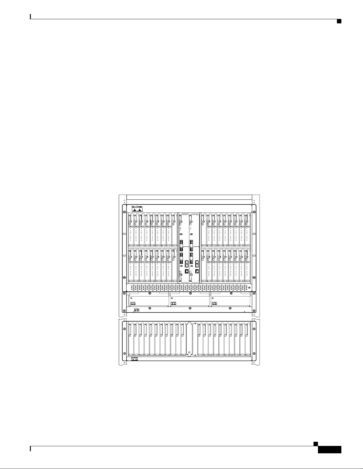
Figure 1-1 shows the components for a Cisco 6130 chassis with a POTS splitter configuration.
Figure 1-1 Cisco 6130 with a POTS Splitter Configuration
Introduction to the Cisco 6130 with NI-2 System
Cisco 6130
(4xDMT,
4xflexi)
Fan tray
Cisco 6120
or 3rd-party
POTS splitter
NI-2
NI-2
-155SM-155SM
-155SM-155SM
STATUS
STATUS
STATUS
STATUS
STATUS
STATUS
STATUS
ACTIVE
ACTIVE
ACTIVE
ACTIVE
CAP
CAP
CAP
CAP
DMT
DMT
DMT
DMT
G.LITE
G.LITE
G.LITE
G.LITE
A1
A1
A1
A1
A2
A2
A2
A2
A3
A3
A3
A3
A4
A4
A4
A4
1
23456789
4X FLEXI
4X FLEXI
4X FLEXI
4X FLEXI
STATUS
STATUS
STATUS
STATUS
ACTIVE
ACTIVE
ACTIVE
ACTIVE
CAP
CAP
CAP
CAP
DMT
DMT
DMT
DMT
G.LITE
G.LITE
G.LITE
G.LITE
A1
A1
A1
A1
A2
A2
A2
A2
A3
A3
A3
A3
A4
A4
A4
A4
21 22 23 24 25 26 27 28 29
4X FLEXI
4X FLEXI
4X FLEXI
4X FLEXI
STATUS STATUS STATUS
12345678 9
STATUS
ACTIVE
ACTIVE
ACTIVE
ACTIVE
CAP
CAP
CAP
CAP
DMT
DMT
DMT
DMT
G.LITE
G.LITE
G.LITE
G.LITE
A1
A1
A1
A1
A2
A2
A2
A2
A3
A3
A3
A3
A4
A4
A4
A4
4X FLEXI
4X FLEXI
4X FLEXI
4X FLEXI
STATUS
STATUS
STATUS
STATUS
ACTIVE
ACTIVE
ACTIVE
ACTIVE
CAP
CAP
CAP
CAP
DMT
DMT
DMT
DMT
G.LITE
G.LITE
G.LITE
G.LITE
A1
A1
A1
A1
A2
A2
A2
A2
A3
A3
A3
A3
A4
A4
A4
A4
4X FLEXI
4X FLEXI
4X FLEXI
4X FLEXI
ACO
ACO
RESET
RESET
TRNK 1
TRNK 1
R
T
R
T
R
T
R
T
X
X
X
X
C
E
C
E
L
S
L
S
S
S
S
S
K
T
K
T
T
T
T
T
A
A
A
A
T
T
T
T
T
T
X
BLANK
ALARMS
R
X
T
X
R
X
SBTD 2
R
T
R
T
X
X
C
E
L
S
S
S
K
T
T
T
A
A
T
T
BLANK
10
1210 11
X
BLANK
ALARMS
R
CRITICAL
CRITICAL
X
MAJOR
MAJOR
MINOR
MINOR
POWER
POWER
STATUS
STATUS
ACTIVE
ACTIVE
T
FAN 1
FAN 1
X
FAN 2
FAN 2
R
C
X
C
N
N
S
S
L
L
SBTD 2
A
A
U
U
X
X
R
T
R
T
X
X
C
E
L
S
S
S
ACT
ACT
K
T
T
T
A
A
E
E
T
T
N
N
E
E
T
T
LNK
LNK
30 31 32 33 34 35 36 37 38
BLANK
12
13 14 1615 17 18 19 22
Cisco 6100
STATUS
STATUS
STATUS
STATUS
STATUS
STATUS
ACTIVE
ACTIVE
ACTIVE
CAP
CAP
CAP
DMT
DMT
DMT
G.LITE
G.LITE
G.LITE
A1
A1
A1
A2
A2
A2
A3
A3
A3
A4
A4
A4
13 14 15 16 17 18 19 20
4X FLEXI
4X FLEXI
4X FLEXI
STATUS
STATUS
STATUS
ACTIVE
ACTIVE
ACTIVE
CAP
CAP
CAP
DMT
DMT
DMT
G.LITE
G.LITE
G.LITE
A1
A1
A1
A2
A2
A2
A3
A3
A3
A4
A4
A4
4X FLEXI
4X FLEXI
4X FLEXI
STATUS
ACTIVE
ACTIVE
ACTIVE
ACTIVE
CAP
CAP
CAP
CAP
DMT
DMT
DMT
DMT
G.LITE
G.LITE
G.LITE
G.LITE
A1
A1
A1
A1
A2
A2
A2
A2
A3
A3
A3
A3
A4
A4
A4
A4
4X FLEXI
4X FLEXI
4X FLEXI
4X FLEXI
STATUS
STATUS
STATUS
STATUS
ACTIVE
ACTIVE
ACTIVE
ACTIVE
CAP
CAP
CAP
CAP
DMT
DMT
DMT
DMT
G.LITE
G.LITE
G.LITE
G.LITE
A1
A1
A1
A1
A2
A2
A2
A2
A3
A3
A3
A3
A4
A4
A4
A4
4X FLEXI
4X FLEXI
4X FLEXI
4X FLEXI
Cisco 6100
21
2011
Cisco 6120
STATUS
ACTIVE
CAP
DMT
G.LITE
A1
A2
A3
A4
4X FLEXI
STATUS
ACTIVE
CAP
DMT
G.LITE
A1
A2
A3
A4
4X FLEXI
44220
54160
OL-3768-01
Cisco 6130 with NI-2 Hardware Installation Guide
1-3
Page 28

Introduction to the Cisco 6130 with NI-2 System
Note Either a Cisco 6120 or a third-party POTS splitter can be used in a Cisco 6130 with a POTS
splitter configuration.
A system configuration using quad-port line cards requires a POTS splitter capacity of 128
subscriber ports. Each Cisco 6120 POTS splitter supports up to 64 subscribers. Depending on
the POTS splitter selected for your configuration (Cisco 6120 or third-party), the installation of
an additional POTS splitter may be necessary.
Both a Cisco 6120 and a third-party POTS splitter can be used with the same Cisco 6130 chassis;
however, Cisco does not supply the special cables required for this type of POTS configuration.
For third-party POTS splitter port mapping and cable pinout specifications, consult the
appropriate vendor documentation.
Cisco 6130 Without a POTS Splitter Configuration
The Cisco 6130 without a POTS splitter configuration supports up to 128 subscribers through directly
connected modems using either ADSL or SDSL technology. To increase subscribership, you can add
additional chassis to your system.
Chapter 1 Product Overview
This configuration includes the following hardware components:
• Cisco 6130—Maximum of two chassis are allowed per rack.
–
4xDMTs.
–
4xflexis—Configure as CAP, DMT, or G.lite.
–
Quad-port STU-C line cards (4xSDSLs).
–
One or two NI-2 card(s)—DS3/2DS3 or OC-3c/OC-3c.
• Fan tray—A fan tray must be installed under each Cisco 6130 chassis.
In this configuration, the Cisco 6130 connects directly to the main distribution frame (MDF).
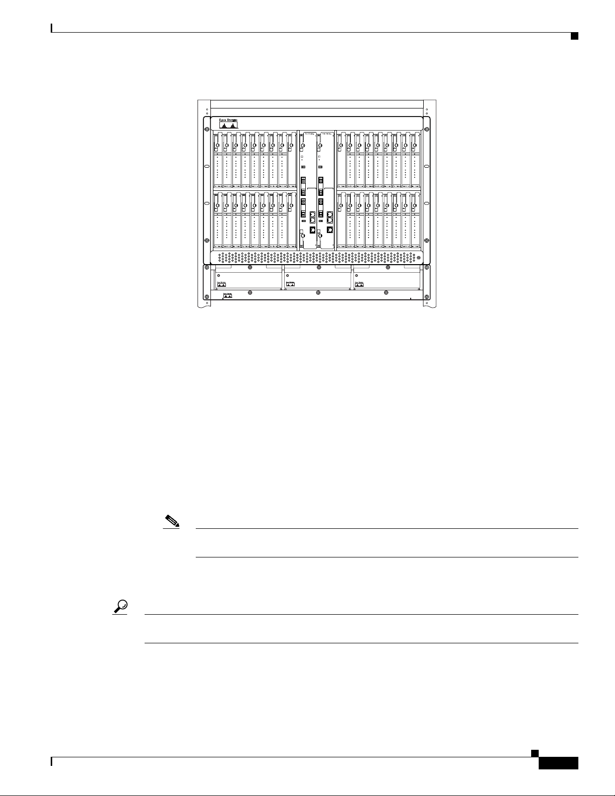
Figure 1-2 shows the components for a Cisco 6130 without a POTS splitter configuration.
1-4
Cisco 6130 with NI-2 Hardware Installation Guide
OL-3768-01
Page 29
Chapter 1 Product Overview
Cisco 6100
Figure 1-2 Cisco 6130 Without a POTS Splitter Configuration
Cisco 6130
(4xDMT,
4xSDSL)
Fan tray
4xflexi,
NI-2
NI-2
-155SM-155SM
-155SM-155SM
STATUS
STATUS
STATUS
STATUS
STATUS
STATUS
STATUS
ACTIVE
ACTIVE
ACTIVE
ACTIVE
CAP
CAP
CAP
CAP
DMT
DMT
DMT
DMT
G.LITE
G.LITE
G.LITE
G.LITE
A1
A1
A1
A1
A2
A2
A2
A2
A3
A3
A3
A3
A4
A4
A4
A4
1
23456789
4X FLEXI
4X FLEXI
4X FLEXI
4X FLEXI
STATUS
STATUS
STATUS
STATUS
ACTIVE
ACTIVE
ACTIVE
ACTIVE
CAP
CAP
CAP
CAP
DMT
DMT
DMT
DMT
G.LITE
G.LITE
G.LITE
G.LITE
A1
A1
A1
A1
A2
A2
A2
A2
A3
A3
A3
A3
A4
A4
A4
A4
21 22 23 24 25 26 27 28 29
4X FLEXI
4X FLEXI
4X FLEXI
4X FLEXI
STATUS STATUS STATUS
STATUS
ACTIVE
ACTIVE
ACTIVE
ACTIVE
CAP
CAP
CAP
CAP
DMT
DMT
DMT
DMT
G.LITE
G.LITE
G.LITE
G.LITE
A1
A1
A1
A1
A2
A2
A2
A2
A3
A3
A3
A3
A4
A4
A4
A4
4X FLEXI
4X FLEXI
4X FLEXI
4X FLEXI
BLANK
STATUS
STATUS
STATUS
STATUS
ACTIVE
ACTIVE
ACTIVE
ACTIVE
CAP
CAP
CAP
CAP
DMT
DMT
DMT
DMT
G.LITE
G.LITE
G.LITE
G.LITE
A1
A1
A1
A1
A2
A2
A2
A2
A3
A3
A3
A3
A4
A4
A4
A4
4X FLEXI
BLANK
4X FLEXI
4X FLEXI
4X FLEXI
ACO
ACO
RESET
RESET
TRNK 1
TRNK 1
R
T
R
T
R
T
R
T
X
X
X
X
C
E
C
E
L
S
L
S
S
S
S
S
K
T
K
T
T
T
T
T
A
A
A
A
T
T
T
T
T
T
X
R
X
T
X
R
X
SBTD 2
R
T
R
T
X
X
C
E
L
S
S
S
K
T
T
T
A
A
T
T
1210 11
X
BLANK
ALARMS
ALARMS
R
CRITICAL
CRITICAL
X
MAJOR
MAJOR
MINOR
MINOR
POWER
POWER
STATUS
STATUS
ACTIVE
ACTIVE
T
FAN 1
FAN 1
X
FAN 2
FAN 2
R
C
X
C
N
N
S
S
L
L
SBTD 2
A
A
U
U
X
X
R
T
R
T
X
X
C
E
L
S
S
S
ACT
ACT
K
T
T
T
A
A
E
E
T
T
N
N
E
E
T
T
LNK
LNK
30 31 32 33 34 35 36 37 38
BLANK
Introduction to the Cisco 6130 with NI-2 System
Cisco 6100
STATUS
STATUS
STATUS
STATUS
STATUS
STATUS
ACTIVE
ACTIVE
ACTIVE
CAP
CAP
CAP
DMT
DMT
DMT
G.LITE
G.LITE
G.LITE
A1
A1
A1
A2
A2
A2
A3
A3
A3
A4
A4
A4
13 14 15 16 17 18 19 20
4X FLEXI
4X FLEXI
4X FLEXI
STATUS
STATUS
STATUS
ACTIVE
ACTIVE
ACTIVE
CAP
CAP
CAP
DMT
DMT
DMT
G.LITE
G.LITE
G.LITE
A1
A1
A1
A2
A2
A2
A3
A3
A3
A4
A4
A4
4X FLEXI
4X FLEXI
4X FLEXI
STATUS
ACTIVE
ACTIVE
ACTIVE
ACTIVE
CAP
CAP
CAP
CAP
DMT
DMT
DMT
DMT
G.LITE
G.LITE
G.LITE
G.LITE
A1
A1
A1
A1
A2
A2
A2
A2
A3
A3
A3
A3
A4
A4
A4
A4
4X FLEXI
4X FLEXI
4X FLEXI
4X FLEXI
STATUS
STATUS
STATUS
STATUS
ACTIVE
ACTIVE
ACTIVE
ACTIVE
CAP
CAP
CAP
CAP
DMT
DMT
DMT
DMT
G.LITE
G.LITE
G.LITE
G.LITE
A1
A1
A1
A1
A2
A2
A2
A2
A3
A3
A3
A3
A4
A4
A4
A4
4X FLEXI
4X FLEXI
4X FLEXI
4X FLEXI
Cisco 6100
STATUS
ACTIVE
CAP
DMT
G.LITE
A1
A2
A3
A4
4X FLEXI
STATUS
ACTIVE
CAP
DMT
G.LITE
A1
A2
A3
A4
4X FLEXI
44220
54138
Subtended Network Configuration
A subtended network configuration
• Services and aggregates the data from one or more remotely located Cisco 6130 chassis into a
subtending host chassis to take advantage of the data network interface on the subtending
host chassis
• Provides additional benefits by reducing the number of ATM edge-switch ports that are required to
terminate the chassis
• Supports both a Cisco 6130 with a POTS splitter and a Cisco 6130 without a POTS
splitter configuration
• Supports NI-2 card cold redundancy in subtended node chassis if both the subtending host chassis
and the subtended node chassis have primary and secondary NI-2 cards installed
Note An NI-2 card failure on a node in a subtend tree or daisy-chain temporarily interrupts traffic
to all subtended node chassis.
• Supports APS link redundancy on subtended OC-3c interfaces if both the subtending host chassis
and the subtended node chassis have primary and secondary NI-2 cards installed
Tip The term subtending refers to the host chassis, and subtended refers to the downstream chassis in a
subtended network.
OL-3768-01
Cisco 6130 with NI-2 Hardware Installation Guide
1-5
Page 30

Introduction to the Cisco 6130 with NI-2 System
A subtended network configuration supports the following features:
• The capacity to run data as fast as the speed of its subtended link. Uplink speed cannot exceed the
OC-3c speed.
• Four arbitration priorities, one for each quality of service (QoS) level. The supported QoS service
levels are
–
Constant bit rate (CBR) for rate-limited services that require guaranteed bandwidth and
bounded delay.
–
Variable bit rate real time (VBR-rt) for delay-sensitive voice and video services.
–
Variable bit rate nonreal time (VBR-nrt) for high-priority data services.
–
Unspecified bit rate (UBR) for low-priority data services.
• Explicit forward congestion indication (EFCI) marking for available bit rate (ABR) service support.
• Guaranteed frame rate (GFR).
• Tree or daisy chain configurations for DS3 subtended Cisco 6130 chassis.
• Daisy chain configurations for OC-3c subtended Cisco 6130 chassis.
• Fair access to the trunk port for each subtended chassis.
Chapter 1 Product Overview
• A network trunk port that operates as fast as any subtended link.
• NI-2 card cold redundancy and APS link redundancy. See the “Redundancy Overview” section on
page 1-26 for more information.
The NI-2 card provides three types of subtended network connections:
• A DS3 ATM interface
• A high-speed OC-3c optical ATM interface that supports single-mode fiber (SMF)
intermediate range
• A high-speed OC-3c optical ATM interface that supports multimode fiber (MMF) short range
The following sections detail the three types of subtending network connections.
Subtended Network Configuration with DS3/2DS3 NI-2 Cards
In a subtended network configuration using DS3/2DS3 NI-2 cards, you can subtend a Cisco 6130 chassis
to four tiers, with up to twelve chassis, all connecting through one subtending host chassis to the
ATM backbone.
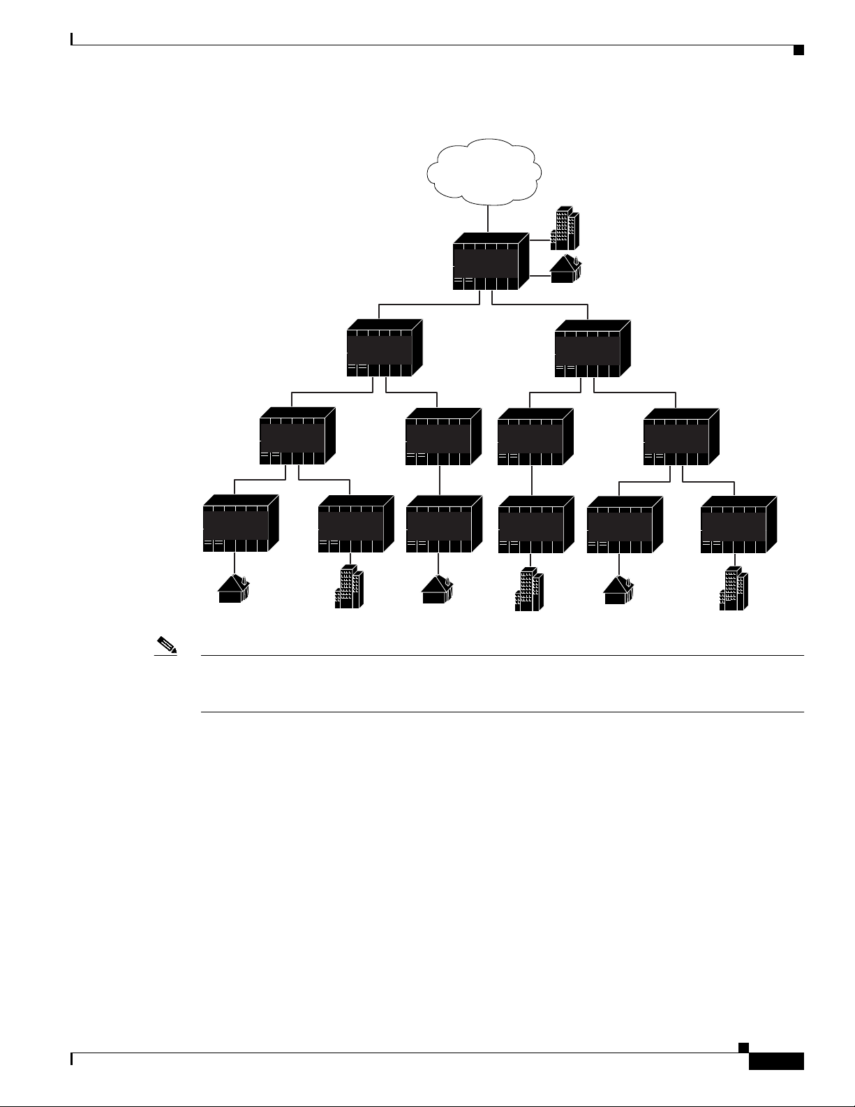
Figure 1-3 shows typical DS3-configured Cisco 6130 systems subtended in a combined subtending tree
topology with daisy chain. The subtending host chassis at the top of the subtending tree connects directly
to the ATM switch. The middle two Cisco 6130 chassis in the lowest level are daisy chained. TRNK 1
refers to the single network trunk or to the Cisco 6130 subtended network interface. SBTD 2 and
SBTD 3 refer to the two Cisco 6130 chassis subtended interfaces. You make network interface
connections at the system I/O card that is installed on the Cisco 6130 backplane.
1-6
Cisco 6130 with NI-2 Hardware Installation Guide
OL-3768-01
Page 31
Chapter 1 Product Overview
Figure 1-3 Subtended Network Configuration Using DS3/2DS3 NI-2 Cards
Introduction to the Cisco 6130 with NI-2 System
ATM
backbone
TRNK 1
Cisco
6100/6130
SBTD 2
TRNK 1
Cisco
6100/6130
TRNK 1
Cisco
6100/6130
SBTD 3
Cisco
6100/6130
SBTD 2
TRNK 1
Cisco
6100/6130
SBTD 2
TRNK 1
SBTD 3
TRNK 1
Cisco
6100/6130
SBTD 2
TRNK 1
Cisco
6100/6130
SBTD 3
Cisco
6100/6130
SBTD 3
Cisco
6100/6130
6100/6130
SBTD 2
TRNK 1
TRNK 1
TRNK 1
Cisco
SBTD 3
6100/6130
TRNK 1
Cisco
6100/6130
SBTD 2
TRNK 1
Cisco
SBTD 3
TRNK 1
Cisco
6100/6130
27888
Note You can subtend Cisco 6130 chassis with DS3/2DS3 NI-2 cards in a continuous daisy chain. However,
this subtending scheme is not optimal for data throughput for Cisco 6130 chassis that use DS3/2DS3
NI-2 cards.
OL-3768-01
Cisco IOS software does not manage the primary Cisco 6130 chassis and all subtended Cisco 6130
chassis as a single large Cisco 6130 with NI-2 system. Each Cisco 6130 supports an independent
Cisco IOS processor and Management Information Base (MIB).
Cisco 6130 with NI-2 Hardware Installation Guide
1-7
Page 32
Cisco 6130 Chassis Overview
Subtended Network Configuration with OC-3c/OC-3c NI-2 Cards
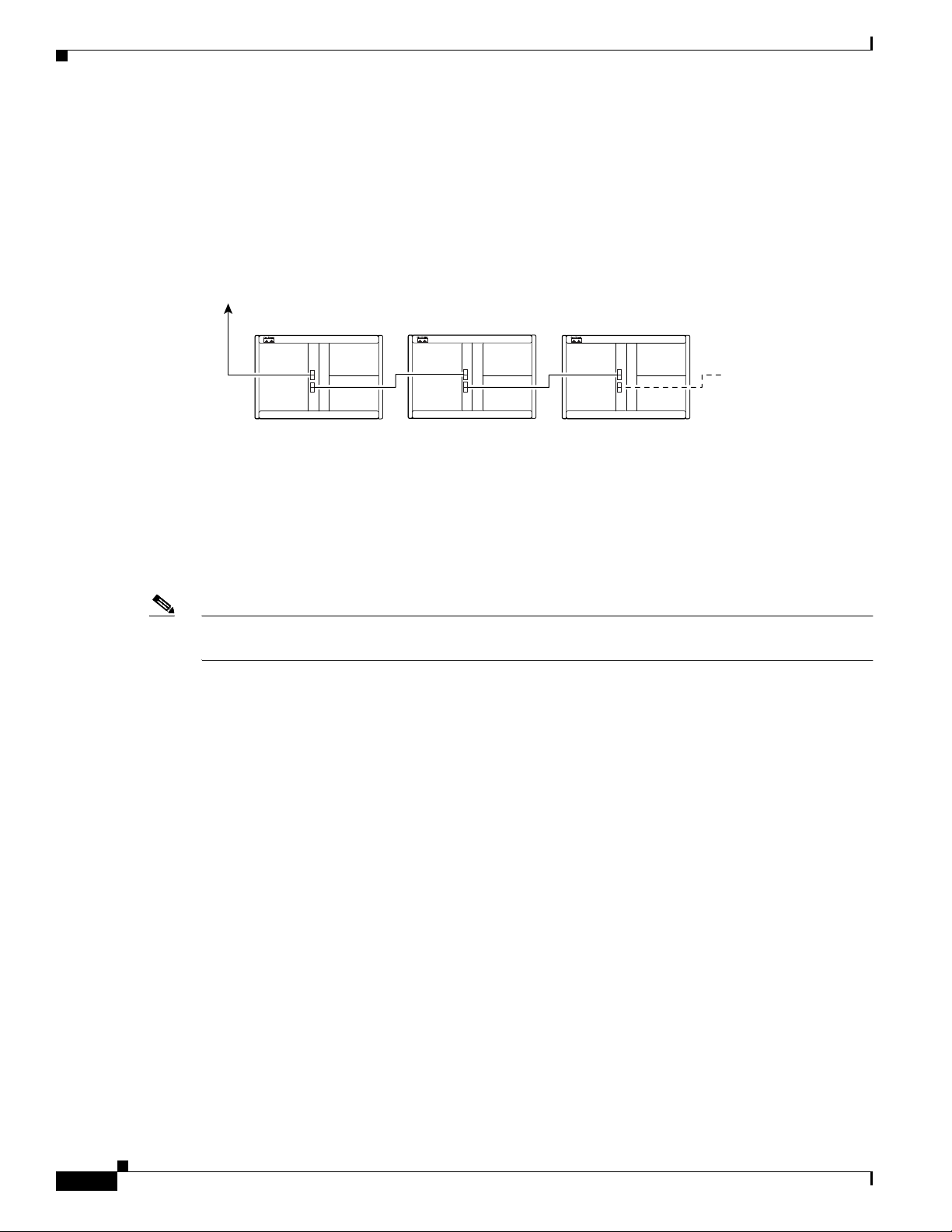
In a subtended network configuration using OC-3c/OC-3c NI-2 cards (SMF or MMF), you can subtend
up to twelve OC-3c configured chassis in a daisy chain, all connecting through one subtending host
chassis to the ATM backbone (see Figure 1-4).
Figure 1-4 Subtended Network Configuration Using OC-3c/OC-3c NI-2 Cards
Network
trunk
To p
chassis
Cisco 6100/6130
Cisco 6130
1st subtended
chassis
Cisco 6130
2nd subtended
chassis
Cisco 6100/6130Cisco 6100/6130
Chapter 1 Product Overview
Cisco 6130
Up to 10 more
subtended
chassis
28069
Cisco 6130 Chassis Overview
The Cisco 6130 chassis uses a 32-slot multiport line card architecture capable of supporting up to 128
ADSL/SDSL ports that are connected either directly or through a POTS splitter.
Note For hardware specifications for the Cisco 6130, see the “Cisco 6130 with NI-2 System Specifications”
section on page A-2.
The following sections detail these Cisco 6130 hardware components:
• Cisco 6130 Card Compartment, page 1-9
• Cisco 6130 Backplane, page 1-10
• Cisco 6130 Cards, page 1-12
• System I/O Card, page 1-28
• Front Cover, page 1-32
• Rear Cover, page 1-32
• Fan Tray, page 1-33
1-8
Cisco 6130 with NI-2 Hardware Installation Guide
OL-3768-01
Page 33

Chapter 1 Product Overview
Cisco 6130 Card Compartment
The card compartment holds all circuitry that relates to the Cisco 6130 with NI-2 system operation.
The card compartment contains 38 slots. Table 1- 1 describes each card slot assignment for the
Cisco 6130.
Table 1-1 Cisco 6130 Card Slot Assignments
Card Slot Card Assignment
1 to 8 4xDMTs, 4xflexis, or 4xSDSLs
9 Blank faceplate
10 NI-2 card (primary)
11 NI-2 card (secondary) or blank faceplate
12 Blank faceplate
13 to 20 4xDMT, 4xflexi, or 4xSDSLs
21 to 28 4xDMT, 4xflexi, or 4xSDSLs
29 and 30 Blank faceplates
31 to 38 4xDMT, 4xflexi, or 4xSDSLs
1. 4xSDSLs can only be used in a Cisco 6130 without a POTS splitter configuration.
2. Blank faceplates must be installed in all open slots of each chassis.
Cisco 6130 Chassis Overview
1
2
2
2
1
1
2
1
Note You can purchase blank faceplates for empty Cisco 6130 card slots.
OL-3768-01
Cisco 6130 with NI-2 Hardware Installation Guide
1-9
Page 34
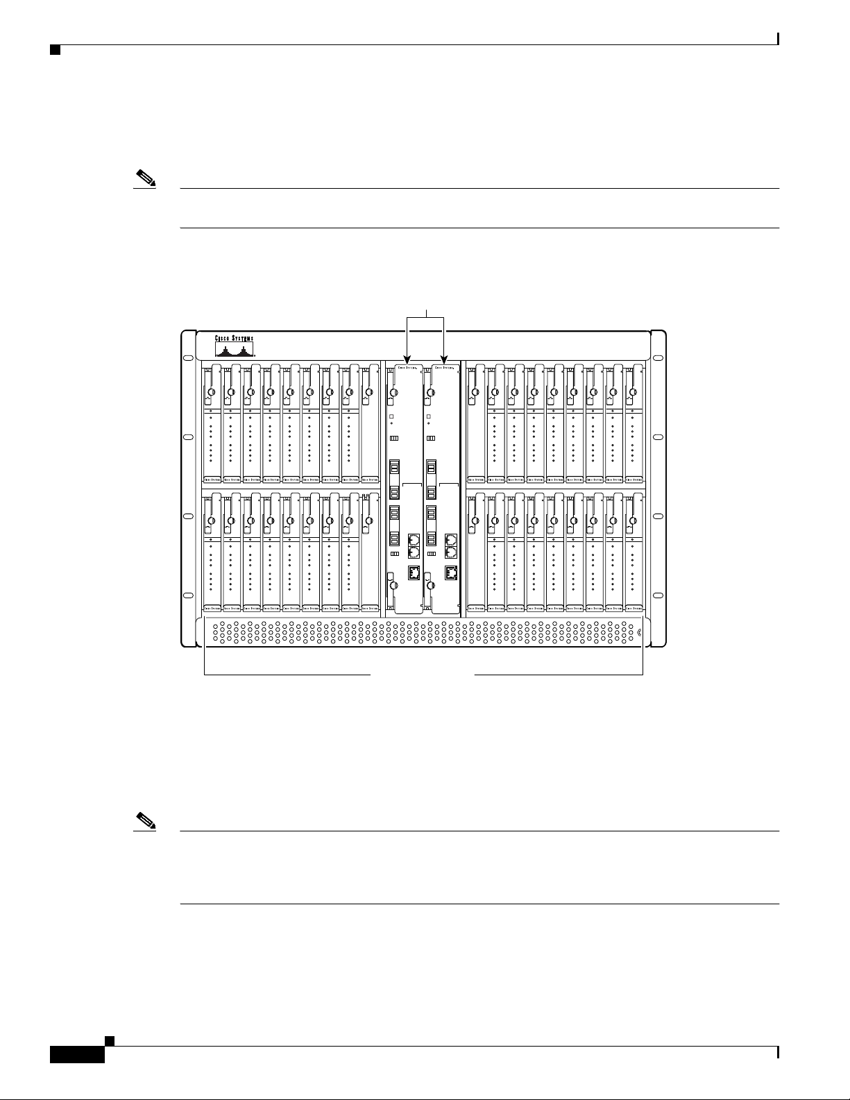
Cisco 6130 Chassis Overview
Figure 1-5 identifies the Cisco 6130 card slots. Each slot on a chassis is numbered along the top of the
chassis. In this guide, the slot numbers are shown on the cards for easy reference and readability. These
slots are referred to in subsequent sections of this chapter and elsewhere in this guide.
Note Figure 1-5 shows the Cisco 6130 without the required front cover installed. The front cover must be
installed while the Cisco 6130 with NI-2 system is in operation.
Figure 1-5 Cisco 6130 Card Slots
STATUS
STATUS
STATUS
STATUS
ACTIVE
ACTIVE
CAP
CAP
DMT
DMT
G.LITE
G.LITE
A1
A1
A2
A2
A3
A3
A4
A4
1
23456789
4X FLEXI
4X FLEXI
4X FLEXI
STATUS
STATUS
ACTIVE
ACTIVE
CAP
CAP
DMT
DMT
G.LITE
G.LITE
A1
A1
A2
A2
A3
A3
A4
A4
21 22 23 24 25 26 27 28 29
4X FLEXI
4X FLEXI
4X FLEXI
STATUS
STATUS
STATUS
ACTIVE
ACTIVE
ACTIVE
CAP
CAP
CAP
DMT
DMT
DMT
G.LITE
G.LITE
G.LITE
A1
A1
A1
A2
A2
A2
A3
A3
A3
A4
A4
A4
4X FLEXI
4X FLEXI
4X FLEXI
STATUS
STATUS
STATUS
ACTIVE
ACTIVE
ACTIVE
CAP
CAP
CAP
DMT
DMT
DMT
G.LITE
G.LITE
G.LITE
A1
A1
A1
A2
A2
A2
A3
A3
A3
A4
A4
A4
4X FLEXI
4X FLEXI
4X FLEXI
STATUS
ACTIVE
ACTIVE
ACTIVE
CAP
CAP
CAP
DMT
DMT
DMT
G.LITE
G.LITE
G.LITE
A1
A1
A1
A2
A2
A2
A3
A3
A3
A4
A4
A4
4X FLEXI
4X FLEXI
STATUS
STATUS
STATUS
ACTIVE
ACTIVE
ACTIVE
CAP
CAP
CAP
DMT
DMT
DMT
G.LITE
G.LITE
G.LITE
A1
A1
A1
A2
A2
A2
A3
A3
A3
A4
A4
A4
4X FLEXI
4X FLEXI
BLANK
BLANK
NI-2
card slots
NI-2
-155SM-155SM
ACO
RESET
TRNK 1
R
T
R
T
X
X
C
E
L
S
S
S
K
T
T
T
A
A
T
T
T
X
ALARMS
R
CRITICAL
X
MAJOR
MINOR
POWER
STATUS
ACTIVE
T
FAN 1
X
FAN 2
R
C
X
N
S
L
SBTD 2
A
U
X
R
T
R
T
X
X
C
E
L
S
S
S
ACT
K
T
T
T
A
A
E
T
T
N
E
T
LNK
Chapter 1 Product Overview
Cisco 6130
NI-2
-155SM-155SM
STATUS
STATUS
ACO
RESET
TRNK 1
R
T
R
T
X
X
C
E
L
S
S
S
K
T
T
T
A
A
T
T
T
X
ALARMS
R
CRITICAL
X
MAJOR
MINOR
POWER
STATU S
ACTIVE
T
FAN 1
X
FAN 2
R
C
X
N
S
L
SBTD 2
A
U
X
R
T
R
T
X
X
C
E
L
S
S
S
ACT
K
T
T
T
A
A
E
T
T
N
E
T
LNK
STATUS
ACTIVE
CAP
DMT
G.LITE
A1
A2
A3
A4
13 14 15 16 17 18 19 20
1210 11
BLANK
4X FLEXI
4X FLEXI
STATUS
ACTIVE
CAP
DMT
G.LITE
A1
A2
A3
A4
30 31 32 33 34 35 36 37 38
BLANK
4X FLEXI
4X FLEXI
STATUS
STATUS
ACTIVE
ACTIVE
ACTIVE
ACTIVE
CAP
CAP
CAP
CAP
DMT
DMT
DMT
DMT
G.LITE
G.LITE
G.LITE
G.LITE
A1
A1
A1
A1
A2
A2
A2
A2
A3
A3
A3
A3
A4
A4
A4
4X FLEXI
STATUS
ACTIVE
CAP
DMT
G.LITE
A1
A2
A3
A4
4X FLEXI
A4
4X FLEXI
4X FLEXI
4X FLEXI
STATUS
STATUS
STATUS
ACTIVE
ACTIVE
ACTIVE
CAP
CAP
CAP
DMT
DMT
DMT
G.LITE
G.LITE
G.LITE
A1
A1
A1
A2
A2
A2
A3
A3
A3
A4
A4
A4
4X FLEXI
4X FLEXI
4X FLEXI
STATUS
STATUS
STATUS
ACTIVE
ACTIVE
ACTIVE
CAP
CAP
CAP
DMT
DMT
DMT
G.LITE
G.LITE
G.LITE
A1
A1
A1
A2
A2
A2
A3
A3
A3
A4
A4
A4
4X FLEXI
4X FLEXI
STATUS
STATUS
STATUS
ACTIVE
ACTIVE
ACTIVE
CAP
CAP
CAP
DMT
DMT
DMT
G.LITE
G.LITE
G.LITE
A1
A1
A1
A2
A2
A2
A3
A3
A3
A4
A4
A4
4X FLEXI
4X FLEXI
Cisco 6130 Backplane
Figure 1-6 shows the Cisco 6130 backplane.
Note To determine if you have a Cisco 6130, locate the Cisco 6130 label on the upper right corner
of either the chassis or the front cover of the chassis. Another way to determine if you have
a Cisco 6130 is to locate the J49 connector on the backplane. The Cisco 6100 backplane
does not have this connector.
Cisco 6130 with NI-2 Hardware Installation Guide
1-10
54136
32 universal slots
xTU-C line cards
OL-3768-01
Page 35
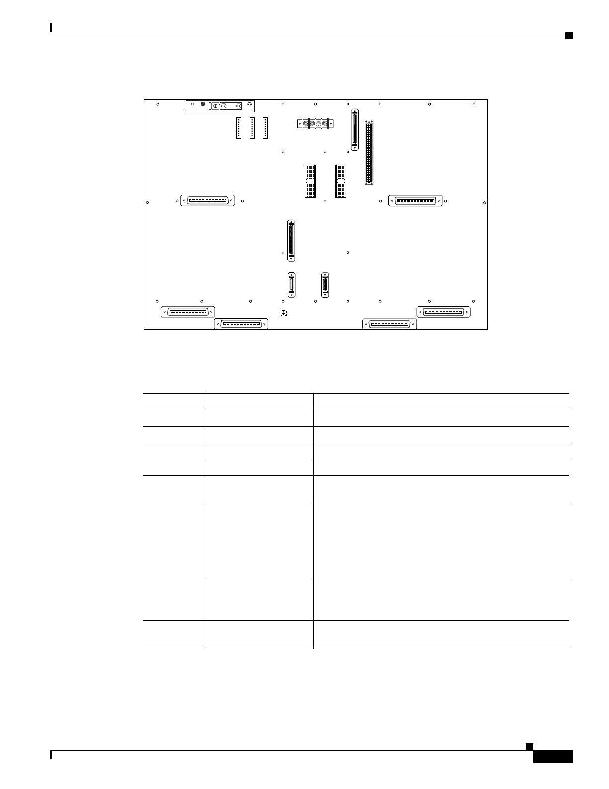
Chapter 1 Product Overview
Figure 1-6 Cisco 6130 Backplane
P14
P15
CRIT
MAJ
MIN
FAN
ALARM
E2A VISUAL AUDIBLE
Cisco 6130 Chassis Overview
J45
MODEM
POOL
P17
CRIT
CRIT
MAJ
MAJ
MIN
MIN
ACO
ACO
-48V_B
-48RTN
P13
A
J48
OUT
-48RTN
-48V_A
J43
J42
J44
MODEM
POOL
B
OUT
ANALOG TEST I/F
P18
J46
J49
RING
TIP
P3P9
J47
J39
J40
J41
22172
Table 1-2 describes the connectors and switches on the Cisco 6130 backplane.
Table 1-2 Cisco 6130 Backplane Connectors and Switches
Identifier Name Description
J45 — Not in use.
J46 — Not in use.
J47 — Not in use.
J48 — Not in use.
J49 Fan Tray Connection 26-pin SCSI connector used to connect the fan tray to the
Cisco 6130 chassis.
J39, J40, J41,
J42, J43, J44
Data Six 50-pin Champ connectors used to transfer data between
the Cisco 6130 chassis and the POTS splitter in a Cisco 6130
with a POTS splitter configuration. In a Cisco 6130 without
a POTS splitter configuration, the connectors are used to
transfer data between the Cisco 6130 chassis and the
CPE equipment.
1
P9, P3 System I/O card Two 2-mm HM
modular connectors (male on the
Cisco 6130 backplane and female on the system I/O card)
used to connect the system I/O card.
P13 Power A terminal block connector with four dual-power
connections (–48V_A, –48V_B, and two –48RTN
2
).
OL-3768-01
Cisco 6130 with NI-2 Hardware Installation Guide
1-11
Page 36

Cisco 6130 Chassis Overview
Table 1-2 Cisco 6130 Backplane Connectors and Switches (continued)
Identifier Name Description
P14, P15,
P17
P18 Analog test input A 2-position header for connecting external xDSL
1. HM = hard metric
2. RTN = return (ground)
Cisco 6130 Cards
This section contains the following information about the types of Cisco 6130 cards:
• 4xDMT Overview, page 1-13
• 4xflexi Overview, page 1-15
• 4xSDSL Overview, page 1-18
• DS3/2DS3 NI-2 Card Overview, page 1-20
Chapter 1 Product Overview
— Not in use.
test equipment.
• OC-3c/OC-3c NI-2 Card Overview, page 1-23
Table 1-3 shows the configurations where the Cisco 6130 line cards can operate.
Table 1-3 Cisco 6130 Card and Configuration Compatibility
Line Card
Cisco 6130 with a POTS
Splitter Configuration
Cisco 6130 Without a POTS
Splitter Configuration
4xDMT Yes Yes
1
4xflexi
4xSDSL
1. The 4xflexi feature support for the Cisco 6130 is present in Release 12.1(2)DA or later.
2. The 4xSDSL feature support for the Cisco 6130 is present in Release 12.1(2)DA
or later.
3. 4xSDSL does not support POTS.
Yes Yes
2, 3
No Yes
The Cisco 6130 supports restricted line card intermixing. You can intermix only the 4xflexi (CAP mode)
and the 4xflexi (DMT mode) in the same chassis half. The left half of the chassis comprises slots 1 to 8
and 21 to 28; the right half comprises slots 13 to 20 and 31 to 38. The line card intermixing
configurations that are supported in a Cisco 6130 chassis are
• 4xflexi (CAP mode) and 4xflexi (DMT mode)
• 4xflexi (CAP mode) and 4xSDSL (used in a Cisco 6130 without POTS splitter configuration only)
1-12
• 4xflexi (DMT mode) and 4xSDSL (used in a Cisco 6130 without POTS splitter configuration only)
Caution Other line card intermixing configurations are not currently supported. Mixing incompatible line cards
can cause unpredictable system behavior.
Cisco 6130 with NI-2 Hardware Installation Guide
OL-3768-01
Page 37

Chapter 1 Product Overview
4xDMT Overview
Note For line card intermixing information, see the “Cisco 6130 Cards” section on page 1-12.
Note For hardware specifications for the 4xDMT, see the “4xDMT Specifications” section on page A-3.
Cisco 6130 Chassis Overview
The 4xDMT
• Supports four ADSL modem connections.
• Converts ADSL modulation from the line into digital data streams to and from the NI-2 card.
• Negotiates the line rate with the CPE when it trains and bases the rate on line quality and distance.
If provisioned, the 4xDMT rate adapts to the maximum bit rate negotiable on the line. The maximum bit
rate settings are provisioned in the management software.
The chassis can include up to 32 4xDMTs for a total of 128 ADSL modem connections.
Faceplate Features
The following fixtures are present on the front of the 4xDMT faceplate:
• Locking lever and locking tab
• LEDs
–
STATUS
–
ACTIVE
–
Four port (ATU-C1 through ATU-C4)
• Extraction tab
OL-3768-01
Cisco 6130 with NI-2 Hardware Installation Guide
1-13
Page 38

Cisco 6130 Chassis Overview
Figure 1-7 shows a close-up of the 4xDMT faceplate.
Figure 1-7 4xDMT Faceplate
Chapter 1 Product Overview
Table 1-4 describes the 4xDMT LED indicator functions.
Table 1-4 4xDMT LED Indicators
LED State Function
STATUS Green slow blinking The self-test is in progress.
Green fast blinking The image download is in progress.
Green solid The status is OK.
Red The self-test or line card has failed.
Off The ATU-C line card has a power failure.
ACTIVE Green solid The line card is activated.
Green blinking A digital signal processor firmware download is
in progress.
Off The line card is not in service.
ATU-C 1 Green solid Modem 1 is trained.
Green blinking Training is in progress for modem 1.
Off Modem 1 is idle.
ATU-C 2 Green solid Modem 2 is trained.
Green blinking Training is in progress for modem 2.
Off Modem 2 is idle.
1-14
Cisco 6130 with NI-2 Hardware Installation Guide
OL-3768-01
Page 39

Chapter 1 Product Overview
4xflexi Overview
Cisco 6130 Chassis Overview
Table 1-4 4xDMT LED Indicators (continued)
LED State Function
ATU-C 3 Green solid Modem 3 is trained.
Green blinking Training is in progress for modem 3.
Off Modem 3 is idle.
ATU-C 4 Green solid Modem 4 is trained.
Green blinking Training is in progress for modem 4.
Off Modem 4 is idle.
The 4xflexi
• Supports CAP, DMT, or G.lite line encoding.
• Supports four ADSL modem connections.
• Converts ADSL modulation from the line into digital data streams to and from the NI-2 card.
• Negotiates the line rate with the CPE when it trains and bases the rate on line quality and distance.
Note For line card intermixing information, see the “Cisco 6130 Cards” section on page 1-12.
Note For hardware specifications for the 4xflexi, see the “4xflexi Specifications” section on page A-3.
Edge Connector Key
Note The 4xSDSL card also features the edge connector key.
If provisioned, the 4xflexi rate adapts to the maximum bit rate negotiable on the line. The maximum bit
rate settings are provisioned in the management software.
The Cisco 6130 system can include up to 32 4xflexis for a total of 128 ADSL modem connections.
The edge connector key, located on the rear of the 4xflexi, connects the 4xflexi to the backplane of the
chassis. There are two edge connector keys available for the 4xflexi: one has six notches and one has
seven notches. You can use both versions in the Cisco 6130 with NI-2 system. Figure 1-8 shows the edge
connector key with seven notches.
OL-3768-01
Cisco 6130 with NI-2 Hardware Installation Guide
1-15
Page 40
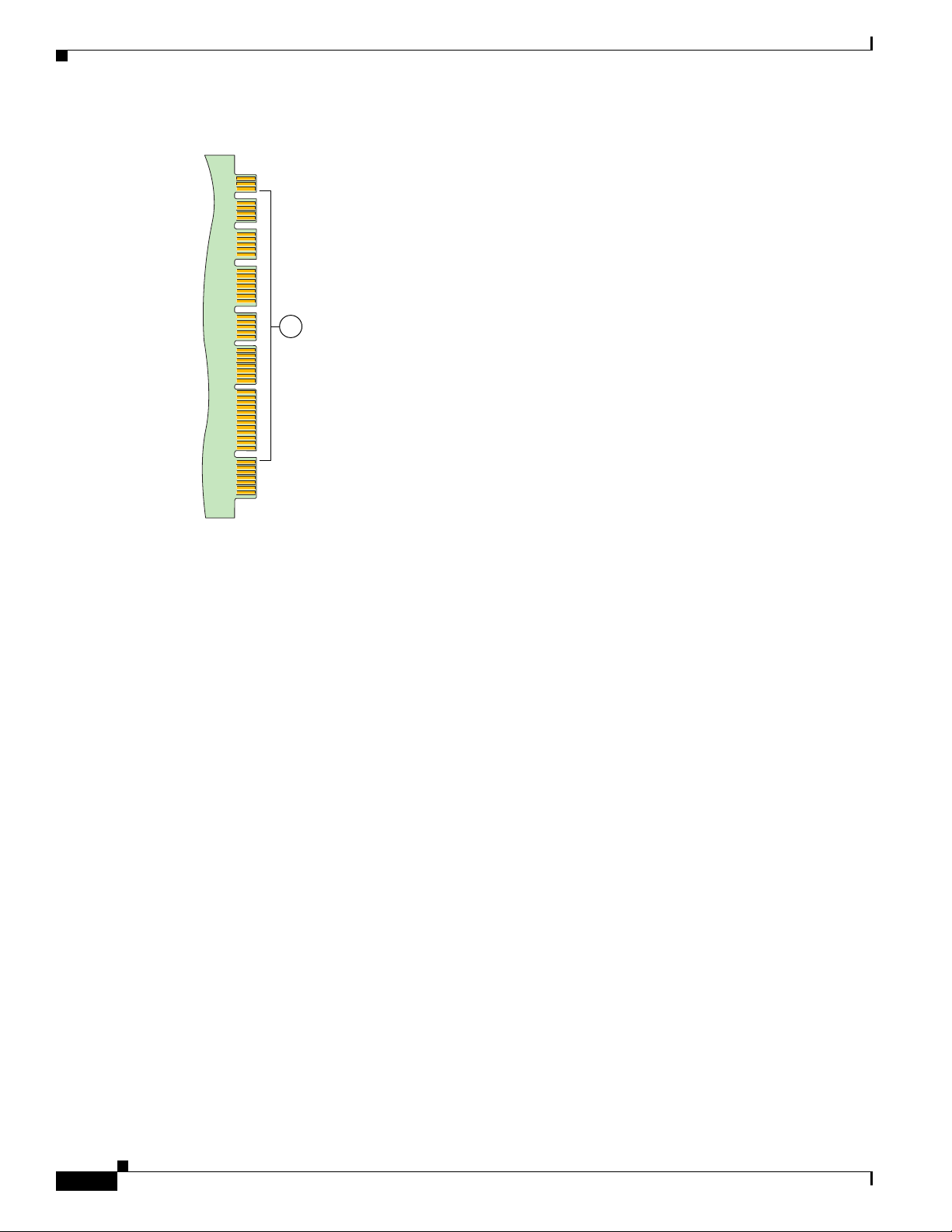
Cisco 6130 Chassis Overview
Figure 1-8 Edge Connector Key
Chapter 1 Product Overview
1
Faceplate Features
38229
The following fixtures are present on the front of the 4xflexi faceplate:
• Locking lever and locking tab
• LEDs
–
STATUS
–
ACTIVE
–
CAP
–
DMT
–
G.LITE
–
Four port (A1 through A4)
• Extraction tab
1-16
Cisco 6130 with NI-2 Hardware Installation Guide
OL-3768-01
Page 41
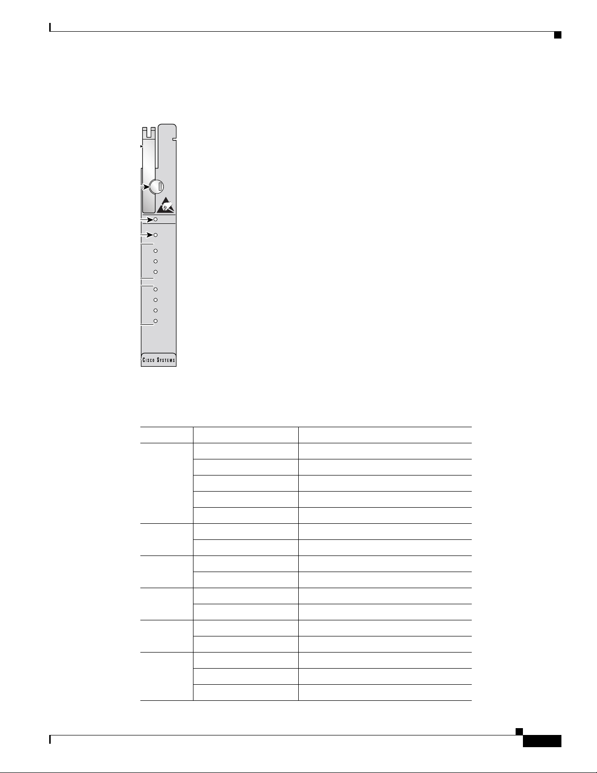
Chapter 1 Product Overview
Figure 1-9 shows a close-up of the 4xflexi faceplate.
Figure 1-9 4xflexi Faceplate
Cisco 6130 Chassis Overview
STATUS
ACTIVE
CAP
DMT
G.LITE
A1
A2
A3
A4
4X FLEXI
28509
Table 1-5 describes the 4xflexi LED indicator functions.
Table 1-5 4xflexi LED Indicators
LED State Function
STATUS Green slow blinking The self-test is in progress.
Green fast blinking The image download is in progress.
Green solid The status is OK.
Red The self-test or line card has failed.
Off The ATU-C line card has a power failure.
ACTIVE Green solid The line card is activated.
Off The line card is not in service.
CAP Green solid The line card is in CAP mode.
Off The line card is not in CAP mode.
DMT Green solid The line card is in DMT mode.
Off The line card is not in DMT mode.
G.LITE Green solid The line card is in G.lite mode.
Off The line card is not in G.lite mode.
A1 Green solid Modem 1 is trained.
Green blinking Training is in progress for modem 1.
Off Modem 1 is idle.
OL-3768-01
Cisco 6130 with NI-2 Hardware Installation Guide
1-17
Page 42

Cisco 6130 Chassis Overview
4xSDSL Overview
Chapter 1 Product Overview
Table 1-5 4xflexi LED Indicators (continued)
LED State Function
A2 Green solid Modem 2 is trained.
Green blinking Training is in progress for modem 2.
Off Modem 2 is idle.
A3 Green solid Modem 3 is trained.
Green blinking Training is in progress for modem 3.
Off Modem 3 is idle.
A4 Green solid Modem 4 is trained.
Green blinking Training is in progress for modem 4.
Off Modem 4 is idle.
The 4xSDSL
Note For line card intermixing information, see the “Cisco 6130 Cards” section on page 1-12.
Note For hardware specifications for the 4xSDSL, see the “4xSDSL Specifications” section on page A-4.
Edge Connector Key
• Supports 2B1Q line encoding.
• Is designed for use in a Cisco 6130 without a POTS splitter configuration.
• Supports four SDSL modem connections.
• Converts SDSL modulation from the line into digital data streams to and from the NI-2 card.
The negotiated bit rate is the lower of the following rates:
• The provisioned bit rate set for the 4xSDSL in the management software
• The assigned bit rate at the CPE
The chassis can include up to 32 4xSDSLs for a total of 128 SDSL modems.
The edge connector key, located on the rear of the 4xSDSL, connects the 4xSDSL to the backplane of
the chassis. There are two edge connector keys available for the 4xSDSL: one has six notches, and the
other has seven notches. You can use both versions in the Cisco 6130 with NI-2 system. Figure 1-8
shows the edge connector key with seven notches.
1-18
Cisco 6130 with NI-2 Hardware Installation Guide
OL-3768-01
Page 43
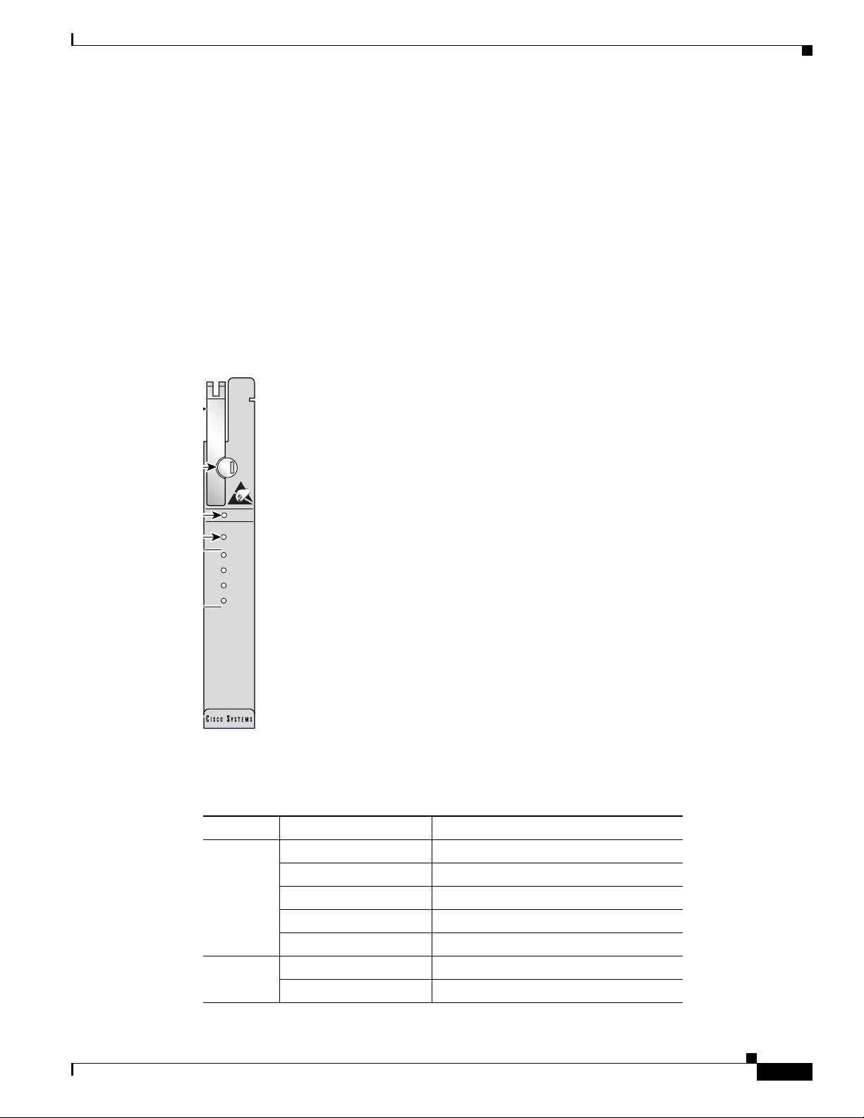
Chapter 1 Product Overview
Faceplate Features
The following fixtures are present on the front of the 4xSDSL faceplate:
• Locking lever and locking tab
• LEDs
–
STATUS
–
ACTIVE
–
Four port (STU-C1 through STU-C4)
• Extraction tab
Figure 1-10 shows a close-up of the 4xSDSL faceplate.
Figure 1-10 4xSDSL Faceplate
Cisco 6130 Chassis Overview
STATUS
ACTIVE
STU-C 1
STU-C 2
STU-C 3
STU-C 4
4X SDSL
2B1Q
18461
Table 1-6 describes the 4xSDSL LED indicator functions.
Table 1-6 4xSDSL LED Indicators
LED State Function
STATUS Green slow blinking The self-test is in progress.
Green fast blinking The image download is in progress.
Green solid The status is OK.
Red The self-test or line card has failed.
Off The ATU-C line card has a power failure.
ACTIVE Green solid The line card is activated.
Off The line card is not in service.
OL-3768-01
Cisco 6130 with NI-2 Hardware Installation Guide
1-19
Page 44

Cisco 6130 Chassis Overview
Table 1-6 4xSDSL LED Indicators (continued)
LED State Function
STU-C 1 Green solid Modem 1 is trained.
STU-C 2 Green solid Modem 2 is trained.
STU-C 3 Green solid Modem 3 is trained.
STU-C 4 Green solid Modem 4 is trained.
Chapter 1 Product Overview
Green blinking Training is in progress for modem 1.
Off Modem 1 is idle.
Green blinking Training is in progress for modem 2.
Off Modem 2 is idle.
Green blinking Training is in progress for modem 3.
Off Modem 3 is idle.
Green blinking Training is in progress for modem 4.
Off Modem 4 is idle.
DS3/2DS3 NI-2 Card Overview
The DS3/2DS3 NI-2 card
• Connects to the xTU-C line cards through point-to-point serial data buses on the backplane
• Controls timing and redundancy
• Provides CO facility alarm relay contact interfaces and an alarm cut-off (ACO) button
• Provides visual and audible operating status alerts
• Contains the ATM switch fabric
• Provides the network DS3 WAN trunk interface through BNC connectors located on the system
I/O card
• Provides two DS3 subtend interfaces through BNC connectors located on the system I/O card
• Supports the aggregation of up to 12 subtended node chassis that are configured for DS3 operation
in a tree topology
• Supports NI-2 card cold redundancy
• Provides Cisco IOS-based ATM Quality of Service (QoS).
The DS3/2DS3 NI-2 card functions are managed by Cisco IOS software. The Cisco IOS software
operates and integrates controller, network trunk, and subtending functions from this single card, which
occupies slot 10, slot 11, or both in a Cisco 6130 chassis.
1-20
Note For DS3/2DS3 NI-2 card hardware specifications, see the “DS3/2DS3 NI-2 Card Specifications” section
on page A-5.
Cisco 6130 with NI-2 Hardware Installation Guide
OL-3768-01
Page 45
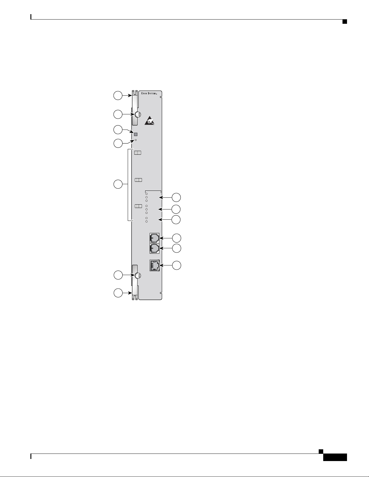
Chapter 1 Product Overview
Faceplate Features
Cisco 6130 Chassis Overview
Figure 1-11 shows a close-up of the DS3/2DS3 NI-2 card faceplate.
Figure 1-11 DS3/2DS3 NI-2 Card Faceplate
1
NI-2
-DS3/E3-DS3/E3
2
3
4
5
2
TRNK 1
R
T
X
E
S
S
T
T
A
T
SBTD 2
T
E
S
T
SBTD 3
T
E
S
T
ACO
RESET
T
R
X
C
L
S
K
T
A
T
R
T
X
X
S
S
T
T
A
A
T
T
R
T
X
X
S
S
T
T
A
A
T
T
R
C
L
K
R
C
L
K
ALARMS
CRITICAL
MAJOR
MINOR
POWER
STATUS
ACTIVE
FAN 1
FAN 2
C
N
S
L
A
U
X
E
N
E
T
6
7
8
9
10
ACT
11
LNK
OL-3768-01
1
44216
The following fixtures are present on the front of the DS3/2DS3 NI-2 card faceplate, as noted in
Figure 1-11:
• Two locking levers with locking tabs.
• An ACO button and a maintenance RESET port located at the top of the faceplate.
Cisco 6130 with NI-2 Hardware Installation Guide
1-21
Page 46

Cisco 6130 Chassis Overview
• Three interface status LED groups, Trunk 1 (TRNK 1), Subtend 2 (SBTD 2), and Subtend 3
Table 1-7 Interface Status LED Group Indicators
LED State Function
TEST Amber solid Cisco IOS detects that an obtrusive test (loopback) is active on
RX STAT Amber solid The receiver detects a physical layer problem.
TX STAT Amber solid The transmitter detects a physical layer problem.
RCLK Green solid Hardware detects an incoming clock signal.
Chapter 1 Product Overview
(SBTD 3), located on the left side of the card faceplate. These interface status LED groups monitor
the trunk and subtend connections on the system I/O card or I/O module.
Table 1-7 describes the interface status LED group indicators and their functions.
this interface.
Off Cisco IOS does not detect obtrusive test activity.
Off The receiver does not detect a physical layer problem.
Off The transmitter does not detect a physical layer problem.
Off Hardware does not detect an incoming clock signal.
• Three alarm status LED groups located on the right side of the NI-2 card faceplate.
–
System alarm LED group
–
Card status LED group
–
Fan alarm LED group
Table 1-8 describes the alarm status LED group indicators and their functions.
Table 1-8 Alarm Status LED Group Indicators
LED Group LED State Function
System
Alarm
CRITICAL Red When this LED is lit, a critical alarm is active.
MAJOR Red When this LED is lit, a major alarm is active.
MINOR Amber When this LED is lit, a minor alarm is active.
Card Status POWER Green When this LED is lit, the NI-2 card has power.
STATUS Green This LED indicates the operational status of the NI-2 card:
• When the LED is lit, there are no internal faults
or problems.
• When the LED is not lit, the NI-2 card has not booted
properly, or a problem is preventing normal operation.
ACTIVE Green When lit, this LED indicates which NI-2 card is operating as
the active network interface in the chassis.
Fan Alarm FAN 1 — This LED on the NI-2 card is inactive and always off. The fan
status LED indicators are on the fan tray.
FAN 2 — This LED on the NI-2 card is inactive and always off. The fan
status LED indicators are on the fan tray.
1-22
Cisco 6130 with NI-2 Hardware Installation Guide
OL-3768-01
Page 47

Chapter 1 Product Overview
• Three operating system interface and internet ports located on the right side of the NI-2
Table 1-9 ENET Interface LED Indicators
LED State Function
ACT Green solid or blinking When the LED is lit or blinking, the Ethernet interface is active.
LNK Green solid When the LED is lit, the Ethernet link is active.
Cisco 6130 Chassis Overview
card faceplate.
–
CNSL—An RJ-45 receptacle that provides a serial connection to a system console.
–
AUX —An RJ-45 receptacle that provides connection to an auxiliary device (such as a modem)
used to remotely configure the system.
–
ENET—An RJ-45 10BaseT receptacle that complies with Ethernet standards and that provides
connection to a system Ethernet. The ENET interface has two LEDs: ACT to indicate activity
status and LNK to indicate link status. Ta ble 1 - 9 describes the ENET interface LED indicators
and their functions.
Off When the LED is unlit, the Ethernet interface is inactive.
OC-3c/OC-3c NI-2 Card Overview
The OC-3c/OC-3c NI-2 card
• Connects to the xTU-C line cards through point-to-point serial data buses on the backplane
• Controls timing and redundancy
• Provides CO facility alarm relay contact interfaces and an ACO button
• Provides visual and audible operating status alerts
• Contains the ATM switch fabric
• Provides the network OC-3c WAN trunk interface through connectors located on the NI-2 card
faceplate. The following two versions of the OC-3c/OC-3c NI-2 card are available to support the
WAN trunk interface:
–
SMF intermediate range
–
MMF short range
• Provides an OC-3c subtend interface through optical connectors located on the NI-2 card faceplate.
• Supports the aggregation of up to 12 subtended node chassis that are configured for OC-3c operation
in a daisy-chain topology
• Supports NI-2 card cold redundancy
• Supports APS link redundancy
• Provides Cisco IOS-based ATM Quality of Service (QoS)
OL-3768-01
Note For OC-3c/OC-3c NI-2 card hardware specifications, see the “OC-3c/OC-3c NI-2 Card Specifications”
section on page A-6.
Cisco 6130 with NI-2 Hardware Installation Guide
1-23
Page 48
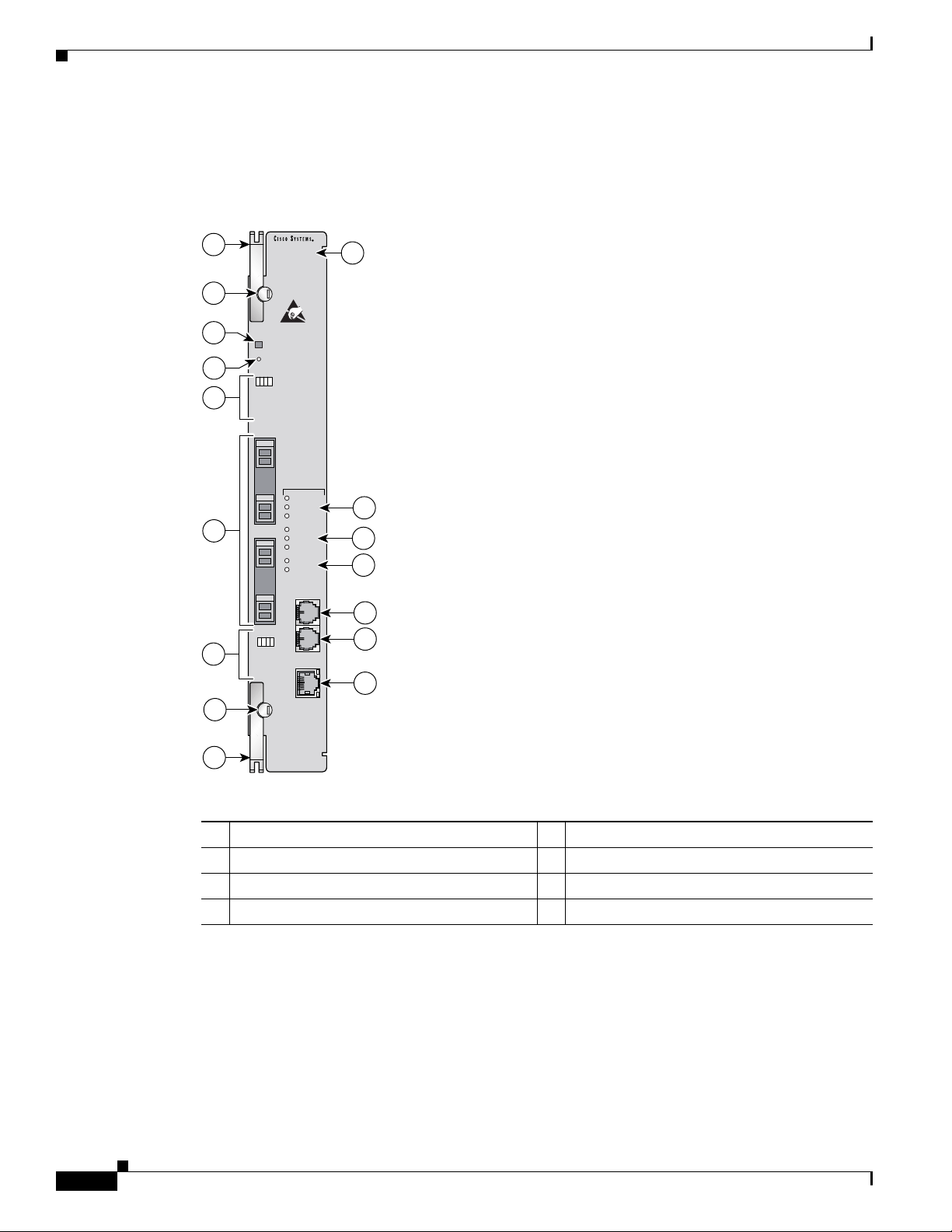
Cisco 6130 Chassis Overview
Faceplate Features
Chapter 1 Product Overview
Figure 1-12 shows a close-up of the OC-3c/OC-3c NI-2 card faceplate.
Figure 1-12 OC-3c/OC-3c NI-2 Card Faceplate
1
NI-2
-155SM-155SM
7
2
3
4
5
6
5
2
ACO
RESET
TRNK 1
R
T
R
T
X
X
C
E
L
S
S
S
K
T
T
T
A
A
T
T
T
X
ALARMS
R
CRITICAL
X
MAJOR
MINOR
POWER
STATUS
ACTIVE
T
FAN 1
X
FAN 2
R
X
C
N
S
L
SBTD 2
A
U
X
R
T
R
T
X
X
C
E
L
S
S
S
K
T
T
A
T
ACT
T
A
E
T
N
E
T
LNK
8
9
10
11
12
13
1-24
1
26372
1 Ejector lever. 7 Model number
2 Locking tab. 8 System alarm LED group.
3 ACO button. 9 Card status LED group.
4 Maintenance RESET port. 10 Fan alarm LED group.
Cisco 6130 with NI-2 Hardware Installation Guide
OL-3768-01
Page 49

Chapter 1 Product Overview
Cisco 6130 Chassis Overview
Interface status LED groups: Trunk 1
(TRNK 1) and Subtend 2 (SBTD 2). These
CNSL—An RJ-45 receptacle that provides a
serial connection to a system console.
groups show the status of the trunk and
subtend connections. 11
5
Two optical interface connector pairs: Trunk 1
(TRNK 1) and Subtend 2 (SBTD 2)
• TRNK 1—This connector pair is for
network trunk interface TX and RX data
AUX—An RJ-45 receptacle that provides
connection to an auxiliary device (such as a
modem) used to remotely configure the
system.
optical cables. On a subtended node
chassis, these network trunk interface TX
and RX cables connect to SBTD 2 on the
subtending host chassis.
• SBTD 2—This connector pair is for
subtended node chassis TX and RX data
6
optical cables. 12
ENET—An RJ-45 10BaseT receptacle that
complies with Ethernet standards and that
13
provides connection to a system Ethernet.
Table 1-1 0 describes the LED group indicators and their functions.
Table 1-10 OC-3c/OC-3c NI-2 Card LED Group Indicators
LED Group LED State Function
Interface
status LED
(5 in
Figure 1-12)
TEST Amber solid Cisco IOS detects that an obtrusive test (loopback) is
active on this interface.
Off Cisco IOS does not detect obtrusive test activity.
RX STAT Amber solid The receiver detects a physical layer problem.
Off The receiver does not detect a physical layer problem.
TX STAT Amber solid The transmitter detects a physical layer problem.
Off The transmitter does not detect a physical layer
problem.
RCLK Green solid Hardware detects an incoming clock signal.
Off Hardware does not detect an incoming clock signal.
System alarm
(8 in
Figure 1-12)
CRITICAL Red A critical alarm is active.
MAJOR Red A major alarm is active.
MINOR Amber A minor alarm is active.
Card status
(9 in
Figure 1-12)
POWER Green The NI-2 card has power.
STATUS Green The operational status of the NI-2 card.
• On—There are no internal faults or problems.
• Off—The NI-2 card has not booted properly, or a
problem is preventing normal operation.
ACTIVE Green The NI-2 card is operating as the active NI-2 card in
the chassis.
OL-3768-01
Cisco 6130 with NI-2 Hardware Installation Guide
1-25
Page 50

Cisco 6130 Chassis Overview
Table 1-10 OC-3c/OC-3c NI-2 Card LED Group Indicators (continued)
LED Group LED State Function
Fan alarm
(10 in
Figure 1-12)
ENET
interface LED
(13 in
Figure 1-12)
Network Clocking Overview
The NI-2 card receives its network timing signal from any one of the following sources:
• A building integrated timing supply (BITS) clock. When a BITS clock serves as the network timing
signal source, the Cisco 6130 chassis receives a clock signal through designated pins on the system
I/O card and distributes the signal through the chassis backplane.
• An internal clock.
Chapter 1 Product Overview
FAN 1 Red The fan module or fan tray is not operational and is in
alarm mode.
FAN 2 — This LED on the NI-2 card is inactive and is
always off.
ACT Green solid or
The Ethernet interface is active.
blinking
Off The Ethernet interface is inactive.
LNK Green solid The Ethernet link is connected and enabled.
• A DS3 or OC-3c network trunk interface. An NI-2 card synchronizes with the network timing source
and provides a clock reference signal to line cards in the chassis and to subtended node chassis.
The active NI-2 card supplies a redundant pair of clock signals to all cards in the chassis. This same
clock reference can be propagated to subtend systems via the trunk and subtended interface ports.
This is done by configuring the subtending port of the root system to source the network-derived
clock. The trunk port of the subtended system is configured as the network clock source for that
chassis. This chain continues down the subtended tree.
Redundancy Overview
Redundancy is available for the Cisco 6130 system. The following forms of redundancy are available:
• NI-2 card cold redundancy, which allows a standby NI-2 card to take over system operations in the
event of a complete failure of the active NI-2 card.
• APS link redundancy, which provides recovery from a cut fiber or the failure of an OC-3c optical
transmitter or optical receiver interface on an NI-2 card. APS link redundancy is available on
OC-3c/2DS3 NI-2 card trunk interfaces and OC-3c/OC-3c NI-2 card trunk and subtend interfaces.
Note Line card redundancy is not currently supported.
NI-2 Card Cold Redundancy
NI-2 card cold redundancy requires that two NI-2 cards be installed in the chassis. The primary card is
installed in slot 10 of the chassis, and the secondary card is installed in slot 11. Either the primary or the
secondary NI-2 card can serve as the active NI-2 card. The interface types must be the same for both the
primary and secondary NI-2 cards.
1-26
In a Cisco 6130 system, NI-2 card cold redundancy is supported by DS3/2DS3, OC-3c/OC-3c SMF, and
OC-3c/OC-3c MMF NI-2 cards.
Cisco 6130 with NI-2 Hardware Installation Guide
OL-3768-01
Page 51

Chapter 1 Product Overview
During steady-state operations, one NI-2 card functions as the active unit, and the other functions as the
standby unit. The active NI-2 card displays a green ACTIVE LED. In an active state, the NI-2 card
• Has full Ethernet, auxiliary port, and console access
• Communicates with line cards
• Has full access to the environmental monitoring subsystem
• Has access to the optical interfaces on the standby NI-2 card
• Allows remote access to the file system of the standby NI-2 card
The standby NI-2 card plays a minimal role during steady-state operations. In a standby state, the
NI-2 card
• Receives configuration changes from the active NI-2 card (when the cards are configured
• Has no Ethernet, auxiliary port, or console access
• Does not communicate with line cards
• Has no access to the environmental monitoring subsystem
• Generates only APS alarms, which are reported via the active card
Cisco 6130 Chassis Overview
for synchronization)
Note For information on NI-2 card cold redundancy switchover conditions, refer to the Upgrading DSLAMs
APS Link Redundancy
For management purposes, the primary and secondary NI-2 cards appear as one element. The cards share
one IP address.
for NI-2 Card and APS Link Redundancy document.
APS link redundancy provides recovery from a cut fiber or the failure of an OC-3c optical transmitter or
receiver interface on an NI-2 card. In a Cisco 6130 system, APS link redundancy is available on
OC-3c/OC-3c NI-2 card trunk and subtend interfaces.
The working link is the fiber connection between the primary NI-2 card installed in slot 10 of the chassis
and the ATM switch. The protection link is the fiber connection between the secondary NI-2 card
installed in slot 11 of the chassis and the ATM switch. When the fiber or optical ports on the active NI-2
card fail, that card remains active but is able to use the fiber or optical ports on the standby NI-2 card.
APS protocol information is carried over the protection link connected to the secondary NI-2 card in
slot 11. The standby NI-2 card continually reports synchronous optical network (SONET) state
information to the active NI-2 card.
APS link redundancy is nonrevertive. For example, after a switchover from the working to the protective
link occurs, the active NI-2 card will switch back to the working fiber only if manually forced through
a CLI command or if a failure condition occurs on the protection link. However, if a failure condition
occurs on the protection link while the working link is still in a failed state, a switch back to the working
link will not occur.
OL-3768-01
Note For information on APS link redundancy switchover conditions, refer to the Upgrading DSLAMs for
NI-2 Card and APS Link Redundancy document.
Cisco 6130 with NI-2 Hardware Installation Guide
1-27
Page 52
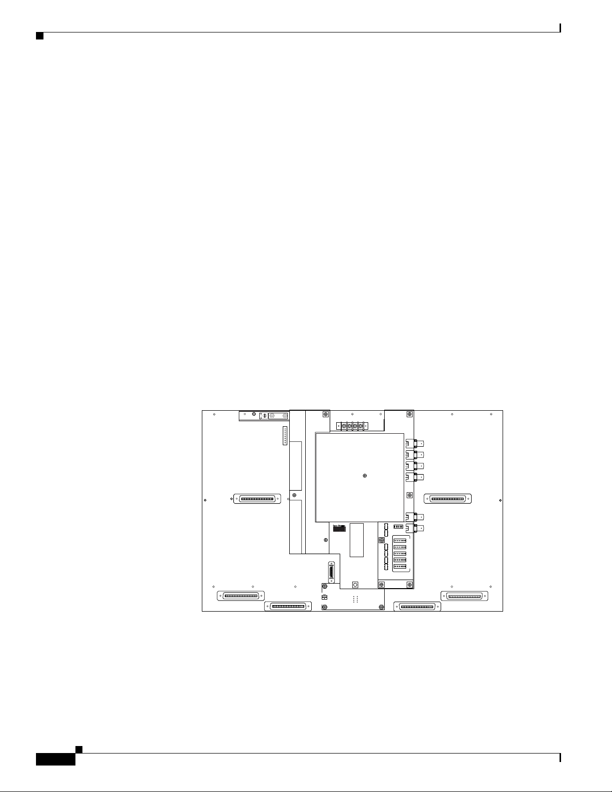
Cisco 6130 Chassis Overview
Redundancy in Subtended Configurations
In Cisco 6130 subtending configurations, NI-2 card redundancy is supported in a DS3 subtend tree or in
an OC-3c subtend daisy-chain if both the subtending host chassis and the subtended node chassis have
primary and secondary NI-2 cards installed. An NI-2 card failure on a node in a subtend tree or
daisy-chain temporarily interrupts traffic to all subtended node chassis.
APS link redundancy is supported on optical interfaces in Cisco 6130 subtending configurations if the
subtending host chassis has a secondary (redundant) OC-3c/OC-3c NI-2 card installed.
System I/O Card
A system I/O card
• Provides transmit and receive Bayonet-Neill-Concelman (BNC) coaxial cable connections for
interfacing with one DS3 network connection and up to two subtended node chassis that use
DS3/2DS3 NI-2 cards.
• Provides relays and contact wire-wrap pins for dedicated CO facility operating alarms (DS3 or
OC-3c systems) that are operated by Cisco IOS software
• Provides the BITS clock
Chapter 1 Product Overview
The system I/O card attaches to the two 2-mm HM card connectors, P3 and P9, on the
Cisco 6130 backplane.
Figure 1-13 shows the location of the system I/O card on the chassis backplane.
Figure 1-13 System I/O Card Locations
MODEM
-48V_B
-48RTN
-48V_A
Cisco 6100/6130
J43
J42
P14
P15
CRIT
MAJ
MIN
FAN
ALARM
E2A VISUAL AUDIBLE
MODEM
POOL
B
OUT
ANALOG TEST I/F
P18
J46
RING
-48RTN
P13
J49
TIP
P17
CRIT
CRIT
MAJ
MAJ
MIN
MIN
ACO
ACO
J44
POOL
A
J48
OUT
J39
P1
P2
P3
P4
P5
J47
U1
J41
J40
44222
1-28
Cisco 6130 with NI-2 Hardware Installation Guide
OL-3768-01
Page 53
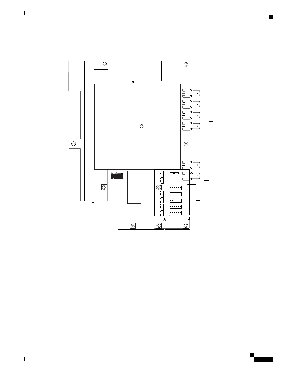
Chapter 1 Product Overview
Figure 1-14 shows a close-up of the system I/O card.
Figure 1-14 System I/O Card
Cisco 6130 Chassis Overview
EMI cover
Safety shield
J14
TX
DS3
J12
J10
RX
TX
trunk I/O
DS3
J8
J6
RX
TX
subtend
DS3
K6
K5
J4
RX
subtend
P1
K4
K3
K2
K1
P2
P3
P4
P5
Wire wrap
headers
(alarm contacts)
27938
OL-3768-01
ESD shield
Table 1-1 1 describes the connectors and headers on the system I/O card.
Table 1-11 System I/O Card Connectors and Headers
Identifier Name Description
J4, J8 DS3 subtend (RX) A 75-ohm BNC connector that is used to connect a
subtending host chassis to a DS3-configured subtended node
chassis TX connector.
J6, J10 DS3 subtend (TX) A 75-ohm BNC connector that is used to connect a
subtending host chassis to a DS3-configured subtended node
chassis RX connector.
Cisco 6130 with NI-2 Hardware Installation Guide
1-29
Page 54

Cisco 6130 Chassis Overview
Table 1-11 System I/O Card Connectors and Headers (continued)
Identifier Name Description
J12 DS3 trunk I/O (RX) A 75-ohm BNC connector that is used to connect the trunk
J14 DS3 trunk I/O (TX) A 75-ohm BNC connector that is used to connect the trunk
P1 Alarm wire-wrap
P2 Alarm wire-wrap
header
header
Chapter 1 Product Overview
network RX coaxial cable or used to connect a subtending
host chassis to a DS3-configured subtended node chassis
TX connector.
network TX coaxial cable or used to connect a subtending
host chassis to a DS3-configured subtended node chassis
RX connector.
1
• Pin 1 (left)—AUD
• Pin 2—AUD_CRIT_NO
• Pin 3—AUD_CRIT_NC
• Pin 4—AUD_MAJ
2
_CRIT3_CO
5
6
7
_CO
• Pin 5—AUD_MAJ_NO
• Pin 6 (right)—AUD_MAJ_NC
1
• Pin 1 (left)—AUD_MIN
8
• Pin 2—AUD_MIN_NO
4
_CO
P3 Alarm wire-wrap
1
header
P4 Alarm wire-wrap
1
header
• Pin 3—AUD_MIN_NC
• Pin 4—VIS
9
_CRIT_CO
• Pin 5—VIS_CRIT_NO
• Pin 6 (right)—VIS_CRIT_NC
• Pin 1 (left)—VIS_MAJ_CO
• Pin 2—VIS_MAJ_NO
• Pin 3—VIS_MAJ_NC
• Pin 4—VIS_MIN_CO
• Pin 5—VIS_MIN_NO
• Pin 6 (right)—VIS_MIN_NC
• Pin 1 (left)—DOOR ALARM
• Pin 2—Reserved
• Pin 3—Reserved
• Pin 4—Reserved
• Pin 5—ACO
• Pin 6 (right)—ACO GND
10
_NO
11
1-30
Cisco 6130 with NI-2 Hardware Installation Guide
OL-3768-01
Page 55

Chapter 1 Product Overview
Table 1-11 System I/O Card Connectors and Headers (continued)
Identifier Name Description
P5 Alarm wire-wrap
K1, K2, K3,
K4, K5, K6
1. Each wire-wrap header is connected to a relay contact on the active NI-2 card in the Cisco 6130 chassis through the system
2. AUD = audible.
3. CRIT = critical.
4. CO = com mon.
5. NO = normally open.
6. NC = normally closed.
7. MAJ = major.
8. MIN = minimum.
9. VIS = visual.
10. The ACO button is located on the faceplate of the NI-2 card. This switch turns off the audible alarms that are generated by
11. GND = ground.
12. RX_BITS = receive building-integrated timing source.
header
Audible and visual
alarm relays
I/O card connectors.
the system software.
Cisco 6130 Chassis Overview
1
• Pin 1 (left)—RX_BITS
12
_TIPA
• Pin 2—RX_BITS_RINGA
• Pin 3—RX_BITS_GND/GND
• Pin 4—RX_BITS_TIPB
• Pin 5—RX_BITS_RINGB
• Pin 6 (right)—RX_BITS_GND/GND
Not in use.
An EMI shield is formed by the EMI fence, which is soldered in place on the system I/O card, and the
EMI cover (see Figure 1-14). Printed circuit board fuses, relays, and surge protectors are shielded by two
clear plastic covers: a safety shield and an ESD shield. The EMI cover and protective shields must be in
place during Cisco 6130 with NI-2 system operation.
OL-3768-01
Cisco 6130 with NI-2 Hardware Installation Guide
1-31
Page 56
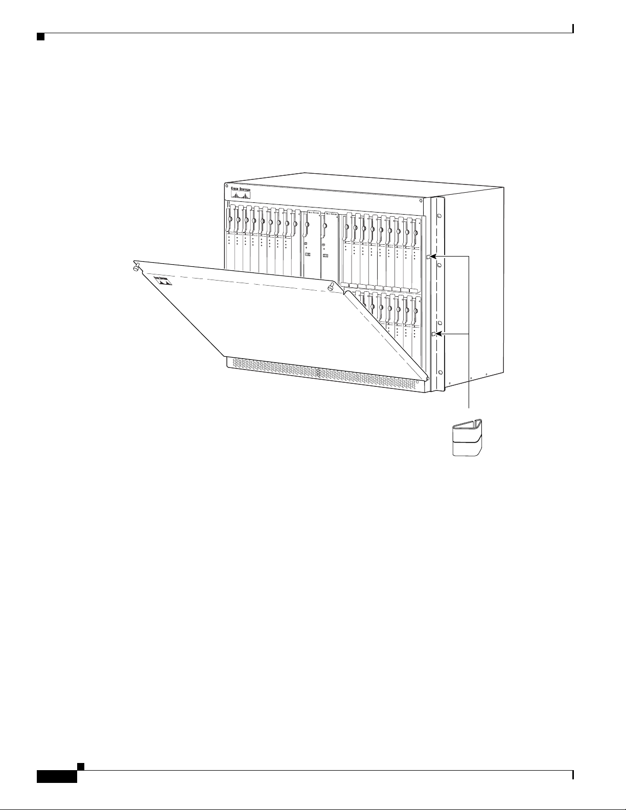
Cisco 6130 Chassis Overview
Cisco 6130
Cisco 6130
Front Cover
Chapter 1 Product Overview
The Cisco 6130 chassis ships with a front cover that must be installed and in place while the system is
in operation, as shown in Figure 1-15.
Figure 1-15 Cisco 6130 Front Cover Installation
NI-2
NI-2
A
CO
A
C
O
R
ES
ET
R
E
SE
T
TRNK 1
TRNK 1
Rear Cover
54139
EMI gaskets
You can order and install an optional rear cover and accessory kit for the Cisco 6130 chassis. The rear
cover attaches to the back of the Cisco 6130 chassis and restricts access to the backplane and cable
connectors. To keep cables from interfering with the opening of the rear cover, the cables that come down
from the top of the rack can be tie wrapped to the cover-mounting brackets.
The rear cover accessory kit contains
• 1 cover-mounting bracket (detached)
• 1 cover-mounting bracket (with the rear cover attached)
• 10 tie wraps
• 6 standoff screws
1-32
Cisco 6130 with NI-2 Hardware Installation Guide
OL-3768-01
Page 57
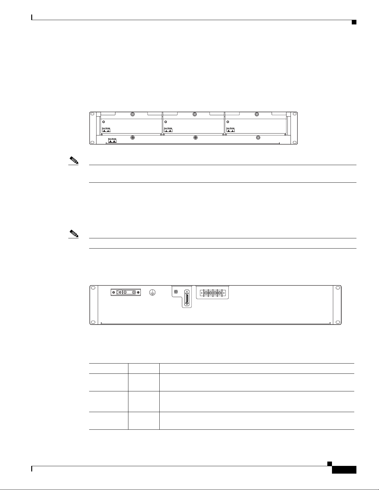
Chapter 1 Product Overview
Cisco 6100
Fan Tray
Cisco 6130 Chassis Overview
The system requires forced air cooling when you use a Cisco 6130 chassis. Therefore, you must install
a fan tray with three fan modules below the chassis and leave 1 rack unit (RU) of space below the fan
tray for intake plenum. Figure 1-16 shows the front view of the fan tray.
Figure 1-16 Fan Tray
STATUS STATUS
STATUS
Cisco 6100
22914
Note The fan tray must be bolted into the rack and connected to the chassis. If you are using multiple
Cisco 6130 chassis in your configuration, a fan tray must be installed under each chassis.
An LED is located on the front of each of the three fan modules. If the LED is
• Green—The fan module is operational.
• Not green—The fan module is not operational and the fan tray is in alarm mode. See Chapter 5,
“Troubleshooting,” for corrective action.
Note For preventive maintenance, see Chapter 6, “Upgrading and Maintaining the Cisco 6130 System.”
Figure 1-17 shows the backplane of the fan tray.
Figure 1-17 Fan Tray Backplane
_
FAN
J1
+
P2
P2
J1
-48V RTN
-48V RTN
P1
RTN
RTN
-48VA
-48VB
OL-3768-01
22915
Table 1-1 2 describes the connectors on the backplane of the fan tray.
Table 1-12 Fan Tray Backplane Connectors
Identifier Name Description
P1 Power Terminal block connector with four dual power input connections (–48VA,
–48VB, and two –48VB RTN).
P2 — A two-position header providing connections for fan tray alarm contacts.
Not in use.
J1 Alarm 26-pin SCSI connector used to connect the fan tray to the
Cisco6130chassis.
Cisco 6130 with NI-2 Hardware Installation Guide
1-33
Page 58

Cisco 6120 POTS Splitter Overview
Cisco 6120 POTS Splitter Overview
The Cisco 6120 POTS splitter is a device that separates voice frequencies from DSL signals. It is used
to allow POTS service to continue over communication lines accessed by DSL equipment such as the
Cisco 6130 chassis. POTS frequencies are sent to the voice switch and xDSL frequencies are routed to
the ATU-C line cards, depending on the configuration you install. The Cisco 6120 is electrically passive.
Therefore, a complete loss of power to the Cisco 6130 with NI-2 system does not affect voice transport
to the Public Switched Telephone Network (PSTN).
To colocate voice-switching equipment through the CO MDF, use separate 50-pin Champ connectors to
cable to POTS signals. Special cables are required for this connection. Obtain these cables from Cisco,
or build the cables according to a standard, accepted cable specification, for example, the Nortel
NT-T100 series cable specification. For more information on the required cables, see Appendix B,
“Cable and Port Mapping Specifications.”
Note Refer to the appropriate vendor documentation for information on the third-party POTS splitter.
Chapter 1 Product Overview
Cisco 6120 Card Compartment
The card compartment includes 22 slots. Table 1 - 13 describes each card slot assignment for the
Cisco 6120.
Table 1-13 Cisco 6120 Card Slot Assignments
Card Slot Card Assignment
1 to 10 DMT POTS cards only
11 Blank faceplate
12 Screwed-down faceplate
13 to 22 DMT
1. Blank faceplates must be installed in all open slots of each chassis.
Note You can purchase blank faceplates for empty Cisco 6120 card slots.
1
POTS cards only
1-34
Cisco 6130 with NI-2 Hardware Installation Guide
OL-3768-01
Page 59
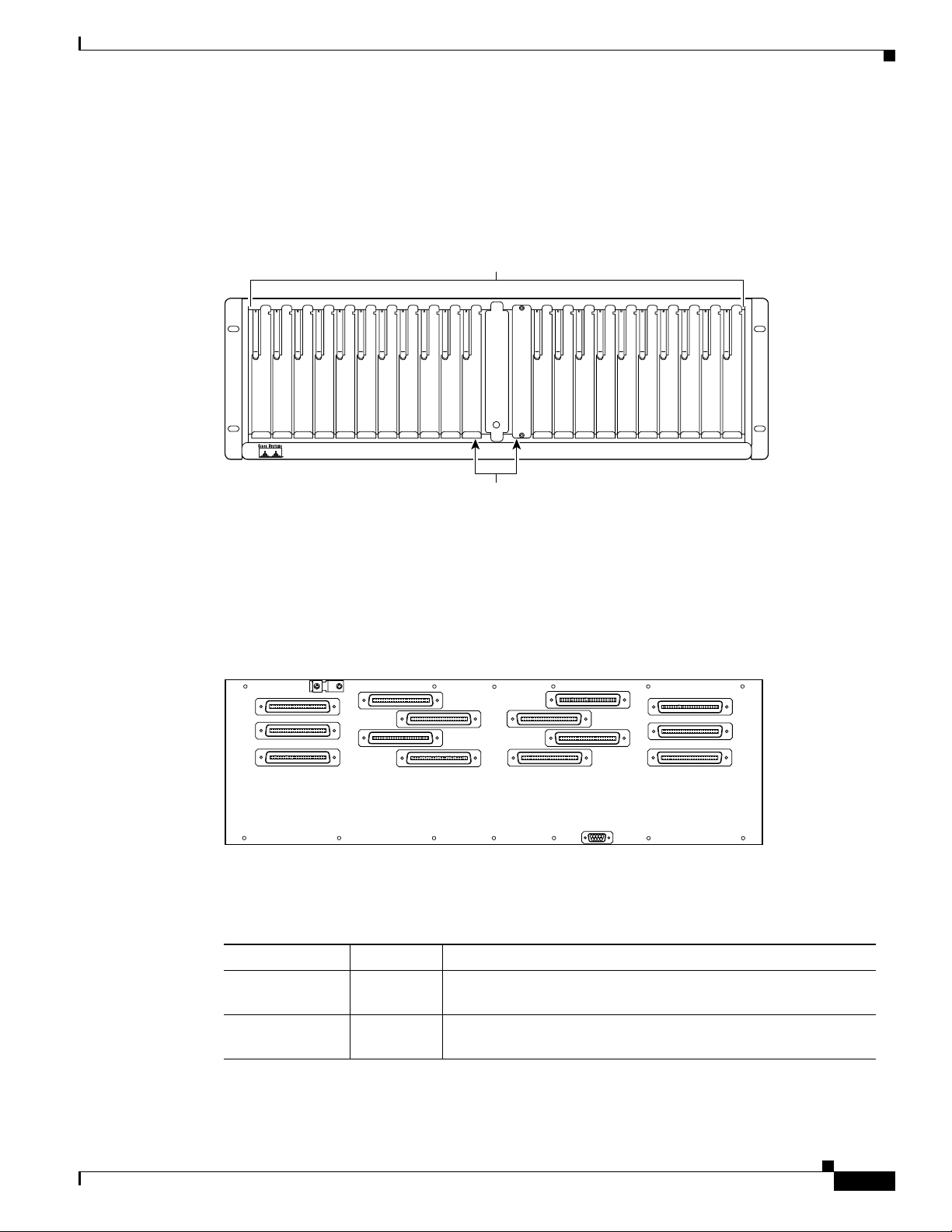
Chapter 1 Product Overview
Cisco 6120
Figure 1-18 identifies the Cisco 6120 card slots. Each slot on a chassis is numbered along the top of the
chassis. In this guide, the slot numbers are shown on the cards for easy reference and readability. These
slots are referred to in subsequent sections of this chapter and elsewhere in this guide.
Figure 1-18 Cisco 6120 Card Slots
Cisco 6120 POTS Splitter Overview
Supports up to 20
POTS splitter cards
123456789
Cisco 6120 Backplane
Figure 1-19 shows the backplane of the Cisco 6120.
Figure 1-19 Cisco 6120 Backplane
J4
J8
J14
10
J2
J10
Unused
J6
J13
13
14 1615 17 18 19 22
12
J1
J5
J9
J12
J36
21
2011
PSMPSMPSMPSMPSMPSMPSMPSMPSMPSMPSM PSM PSM PSM PSM PSM PSM PSM PSM PSM BLANK
39537
J3
J7
J11
18413
OL-3768-01
Table 1-1 4 describes the connectors on the backplane of the Cisco 6120.
Table 1-14 Cisco 6120 Backplane Connectors
Identifier Connector Description
J1 through J6 — Six 50-position Champ connectors for connection to the
Cisco 6130 chassis.
J7 through J10 Voice Four 50-position Champ connectors for connection to external
voice terminating equipment.
Cisco 6130 with NI-2 Hardware Installation Guide
1-35
Page 60
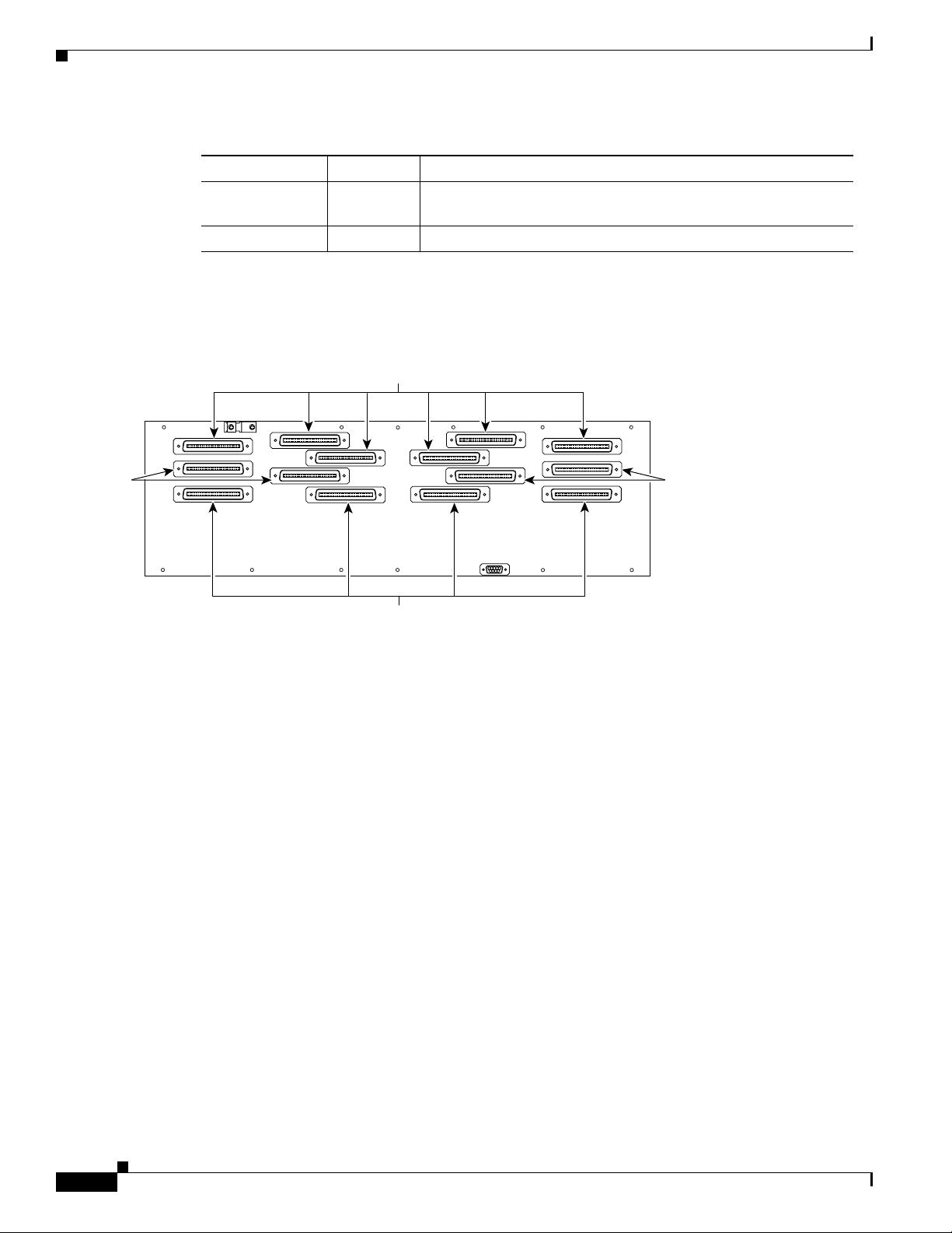
Cisco 6120 POTS Splitter Overview
Table 1-14 Cisco 6120 Backplane Connectors (continued)
Identifier Connector Description
J11 through J14 Line Four 50-position Champ connectors for incoming xDSL
J36 — One 9-pin D-sub connector reserved for future use.
Figure 1-20 shows the location of the Cisco 6120 data, voice, and line connections.
Figure 1-20 Cisco 6120 Connections
Chapter 1 Product Overview
voice/data connections.
Data
connections
Voice
connections
J4
J8
J14
J2
J6
J10
J13
Line
connections
J36
J5
J12
J1
J9
J3
J7
J11
Voice
connections
18373
1-36
Cisco 6130 with NI-2 Hardware Installation Guide
OL-3768-01
Page 61
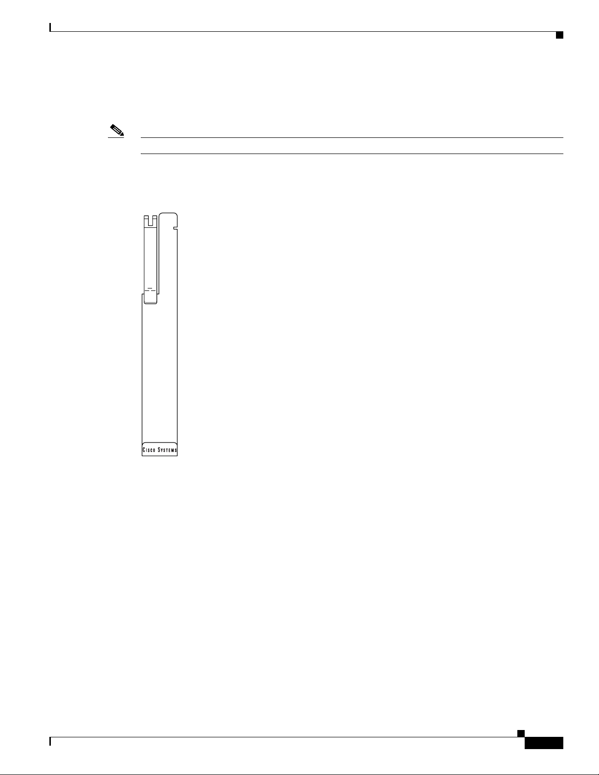
Chapter 1 Product Overview
Cisco 6120 Cards
The DMT POTS card separates ADSL data from the POTS signals.
Note The Cisco 6130 with a POTS splitter configuration will support the 8 kHz DMT POTS card.
Figure 1-21 shows the DMT POTS card faceplate.
Figure 1-21 DMT POTS Card Faceplate
Management Software
PSM
8 kHz-DMT
32022
Management Software
You can provision and manage the Cisco 6130 with NI-2 system through the following
management software:
• Cisco IOS—A CLI that is available for network element provisioning.
• CDM—A GUI designed to configure and manage the 6xxx series of Cisco IOS software-based
DSLAMs. CDM provides the following areas of network management—fault, configuration,
performance, and security. CDM runs with the Cisco EMF; both are installed on Sun workstations.
Cisco EMF is based on an object model in which network elements or modules represent the
managed entity. Each object is defined by a class and specific attributes. An object can represent a
network element or a more abstract entity such as a link relationship, a network, or a container such
as a site, shelf, or region.
OL-3768-01
Cisco 6130 with NI-2 Hardware Installation Guide
1-37
Page 62

Management Software
Note See the “Hardware Specifications” section on page A-1 for minimum software and network management
Chapter 1 Product Overview
Note If your network contains multiple Sun workstations, you must dedicate one workstation as the
server and all additional workstations as clients. The server should be the repository and
distributor of database information from which the clients request information. The client
workstations allow multiple users to monitor the managed network.
release requirements per Cisco 6130 chassis component.
The supported alarms that are generated by the management software are
• CRITICAL—A critical visual alarm condition is indicated when the CRITICAL LED in the NI-2
card faceplate lights.
–
When a critical alarm occurs, the critical visual and audible alarm relays are activated.
–
A critical alarm affects many or all subscribers that are connected to the node (for example,
failure of the NI-2 card or the trunk can cause a critical alarm).
–
Critical alarms clear after you fix the condition that triggered the alarm.
–
Audible alarms are turned off when you press the ACO button on the NI-2 card faceplate.
• MAJOR—A major visual alarm condition is indicated when the MAJOR LED in the NI-2 card
faceplate lights.
–
When a major alarm occurs, the major visual and audible alarm relays are also activated.
–
Several subscribers that are connected to the node are affected.
–
Major alarms clear after you fix the condition that triggered the alarm.
–
Audible alarms are turned off when you press the ACO button on the NI-2 card faceplate.
• MINOR—A minor visual alarm condition is indicated when the MINOR LED in the NI-2 card
faceplate lights.
–
When a minor alarm occurs, the minor visual and audible alarm relays are also activated.
–
A small number of subscribers that are connected to the node are affected.
–
Minor alarms clear after you fix the condition that triggered the alarm.
–
Audible alarms are turned off when you press the ACO button on the NI-2 card faceplate.
Visual and audible alarm relay contacts can be wired from the Cisco 6130 chassis to CO alarm devices
(remote lights or bells) located anywhere within the facility.
The visual and audible alarm relays are located on the system I/O card, but the NI-2 card hardware
operates them. The visual alarms clear after you fix the problem that triggered the alarm. The audible
alarms can be disabled by pressing the ACO button on the NI-2 card or clearing the alarm in the Cisco
IOS software.
1-38
For more information on alarms that are generated in the management software, see Chapter 5,
“Troubleshooting.”
Cisco 6130 with NI-2 Hardware Installation Guide
OL-3768-01
Page 63

CHAPTER
2
Preparing for Installation
This chapter provides the requirements that are necessary to prepare for the installation of the Cisco 6130
with NI-2 system.
The chapter contains the following sections:
• Safety Requirements, page 2-1
• Site Requirements, page 2-10
• Required Tools and Equipment, page 2-15
• Unpacking the Cisco 6130 System, page 2-17
• Verifying Contents, page 2-17
• Inspecting for Damage, page 2-18
Caution Before you start the installation procedures, read the entire chapter for important information and safety
warnings.
Safety Requirements
This section describes safety requirements for the Cisco 6130 with NI-2 system. Before you install the
Cisco 6130 with NI-2 system, ensure that all the criteria in this section are met. The section describes
the following safety requirements:
• Safety Guidelines, page 2-1
• Maintaining Safety with Electricity, page 2-8
• Preventing Electrostatic Discharge Damage, page 2-9
• General Maintenance Guidelines, page 2-9
Safety Guidelines
Before working on the equipment, be aware of standard safety guidelines and the hazards involved in
working with electrical circuitry to prevent accidents. Adhere to the following guidelines, cautions, and
warnings and those throughout the guide for safe and hazard-free installation.
OL-3768-01
Cisco 6130 with NI-2 Hardware Installation Guide
2-1
Page 64

Safety Requirements
Tip In the following warnings, the terms cover panel and safety cover refer to the Cisco 6130 chassis front
Caution Before you start the installation procedures, read the entire chapter for important information and safety
Chapter 2 Preparing for Installation
Follow these guidelines to ensure general safety:
• Keep the equipment area clear and dust-free during and after installation.
• Keep tools away from walk areas where you and others could fall over them.
• Do not wear loose clothing that could get caught in the chassis. Fasten ties or scarves and roll up
shirt sleeves.
• Wear safety glasses if you are working under conditions that might be hazardous to your eyes.
• Do not perform any action that makes the equipment unsafe or creates a potential hazard to yourself
or others.
cover.
warnings.
Caution Proper ESD protection is required whenever you handle Cisco equipment. Installation and maintenance
personnel should be properly grounded using ground straps to eliminate the risk of ESD damage to the
equipment. Cards are subject to ESD damage whenever they are removed from the chassis.
Caution Mixing incompatible line cards can cause unpredictable system behavior. See the “Cisco 6130 Cards”
section on page 1-12 for intermixing compatibility.
Caution Be careful when you remove the standoff screws and reinsert the screws into the screw holes on the
backplane so that the backplane circuitry does not become damaged.
Caution Installing the cards in the chassis with the power leads reversed can damage the line cards.
Caution If fuses are already installed in the fuse and alarm panel, remove them. You can replace the fuses after
the system is installed. Do not power up the system while you install and connect the system.
Caution If the power connections are improperly connected and power is applied while the cards are installed,
the cards and chassis could be damaged.
2-2
Caution It is important that the chassis cooling fans run continuously while the system is powered.
Cisco 6130 with NI-2 Hardware Installation Guide
OL-3768-01
Page 65

Chapter 2 Preparing for Installation
Caution Any card that is only partially connected to the backplane can disrupt system operation.
Caution Periodically check the resistance value of the antistatic strap. Ensure that the measurement is between 1
and 10 megohms.
Caution Do not power up the Cisco 6130 chassis while locating or installing the system I/O card or line cards.
Caution Complete all installation procedures before powering up the Cisco 6130 system.
Safety Requirements
Warning
Waarschuwing
Varoitus
Attention
This warning symbol means danger. You are in a situation that could cause bodily injury. Before you
work on any equipment, be aware of the hazards involved with electrical circuitry and be familiar
with standard practices for preventing accidents. To see translations of the warnings that appear
in this publication, refer to the Regulatory Compliance and Safety Information document that
accompanied this device.
Dit waarschuwingssymbool betekent gevaar. U verkeert in een situatie die lichamelijk letsel kan
veroorzaken. Voordat u aan enige apparatuur gaat werken, dient u zich bewust te zijn van de bij
elektrische schakelingen betrokken risico's en dient u op de hoogte te zijn van standaard
maatregelen om ongelukken te voorkomen. Voor vertalingen van de waarschuwingen die in deze
publicatie verschijnen, kunt u het document Regulatory Compliance and Safety Information
(Informatie over naleving van veiligheids- en andere voorschriften) raadplegen dat bij dit toestel is
ingesloten.
Tämä varoitusmerkki merkitsee vaaraa. Olet tilanteessa, joka voi johtaa ruumiinvammaan. Ennen
kuin työskentelet minkään laitteiston parissa, ota selvää sähkökytkentöihin liittyvistä vaaroista ja
tavanomaisista onnettomuuksien ehkäisykeinoista. Tässä julkaisussa esiintyvien varoitusten
käännökset löydät laitteen mukana olevasta Regulatory Compliance and Safety Information
-kirjasesta (määräysten noudattaminen ja tietoa turvallisuudesta).
Ce symbole d'avertissement indique un danger. Vous vous trouvez dans une situation pouvant
causer des blessures ou des dommages corporels. Avant de travailler sur un équipement, soyez
conscient des dangers posés par les circuits électriques et familiarisez-vous avec les procédures
couramment utilisées pour éviter les accidents. Pour prendre connaissance des traductions
d’avertissements figurant dans cette publication, consultez le document Regulatory Compliance
and Safety Information (Conformité aux règlements et consignes de sécurité) qui accompagne cet
appareil.
OL-3768-01
Cisco 6130 with NI-2 Hardware Installation Guide
2-3
Page 66

Safety Requirements
Chapter 2 Preparing for Installation
Warnung
Avvertenza
Advarsel
Aviso
Dieses Warnsymbol bedeutet Gefahr. Sie befinden sich in einer Situation, die zu einer
Körperverletzung führen könnte. Bevor Sie mit der Arbeit an irgendeinem Gerät beginnen, seien Sie
sich der mit elektrischen Stromkreisen verbundenen Gefahren und der Standardpraktiken zur
Vermeidung von Unfällen bewußt. Übersetzungen der in dieser Veröffentlichung enthaltenen
Warnhinweise finden Sie im Dokument Regulatory Compliance and Safety Information
(Informationen zu behördlichen Vorschriften und Sicherheit), das zusammen mit diesem Gerät
geliefert wurde.
Questo simbolo di avvertenza indica un pericolo. La situazione potrebbe causare infortuni alle
persone. Prima di lavorare su qualsiasi apparecchiatura, occorre conoscere i pericoli relativi ai
circuiti elettrici ed essere al corrente delle pratiche standard per la prevenzione di incidenti. La
traduzione delle avvertenze riportate in questa pubblicazione si trova nel documento Regulatory
Compliance and Safety Information (Conformità alle norme e informazioni sulla sicurezza) che
accompagna questo dispositivo.
Dette varselsymbolet betyr fare. Du befinner deg i en situasjon som kan føre til personskade. Før du
utfører arbeid på utstyr, må du vare oppmerksom på de faremomentene som elektriske kretser
innebærer, samt gjøre deg kjent med vanlig praksis når det gjelder å unngå ulykker. Hvis du vil se
oversettelser av de advarslene som finnes i denne publikasjonen, kan du se i dokumentet
Regulatory Compliance and Safety Information (Overholdelse av forskrifter og
sikkerhetsinformasjon) som ble levert med denne enheten.
Este símbolo de aviso indica perigo. Encontra-se numa situação que lhe poderá causar danos
físicos. Antes de começar a trabalhar com qualquer equipamento, familiarize-se com os perigos
relacionados com circuitos eléctricos, e com quaisquer práticas comuns que possam prevenir
possíveis acidentes. Para ver as traduções dos avisos que constam desta publicação, consulte o
documento Regulatory Compliance and Safety Information (Informação de Segurança e
Disposições Reguladoras) que acompanha este dispositivo.
¡Advertencia!
Varning!
Warning
Warning
Este símbolo de aviso significa peligro. Existe riesgo para su integridad física. Antes de manipular
cualquier equipo, considerar los riesgos que entraña la corriente eléctrica y familiarizarse con los
procedimientos estándar de prevención de accidentes. Para ver una traducción de las advertencias
que aparecen en esta publicación, consultar el documento titulado Regulatory Compliance and
Safety Information (Información sobre seguridad y conformidad con las disposiciones
reglamentarias) que se acompaña con este dispositivo.
Denna varningssymbol signalerar fara. Du befinner dig i en situation som kan leda till personskada.
Innan du utför arbete på någon utrustning måste du vara medveten om farorna med elkretsar och
känna till vanligt förfarande för att förebygga skador. Se förklaringar av de varningar som
förkommer i denna publikation i dokumentet Regulatory Compliance and Safety Information
(Efterrättelse av föreskrifter och säkerhetsinformation), vilket medföljer denna anordning.
The customer 48 volt power system must provide reinforced insulation between the primary AC power
and the 48V DC output.
There is the danger of explosion if the battery is replaced incorrectly. Replace the battery only with
the same or equivalent type recommended by the manufacturer. Dispose of used batteries according
to the manufacturer’s instructions.
2-4
Cisco 6130 with NI-2 Hardware Installation Guide
OL-3768-01
Page 67

Chapter 2 Preparing for Installation
Safety Requirements
Warning
Warning
Warning
Warning
Two people are required to lift the chassis. Grasp the chassis underneath the lower edge and lift with
both hands. To prevent injury, keep your back straight and lift with your legs, not your back.
To prevent bodily injury when mounting or servicing this unit in a rack, you must take special
precautions to ensure that the system remains stable. The following guidelines are provided to ensure
your safety:
—This unit should be mounted at the bottom of the rack if it is the only unit in the rack.
—When mounting this unit in a partially filled rack, load the rack from the bottom to the top with the
heaviest component at the bottom of the rack.
—If the rack is provided with stabilizing devices, install the stabilizers before mounting or servicing
the unit in the rack.
Class 1 laser product.
Use copper conductors only.
Warning
Warning
Warning
Warning
Warning
Warning
A readily accessible two-poled disconnect device must be incorporated in the fixed wiring.
The DS3 ports are not intended to be connected to cables that run outside the building where it is
installed. For any connections outside the building, the DS3 ports must be connected to a network
termination unit (NTU). NTU devices should comply with appropriate national safety standards such
as UL 1950, CSA 950, EN 60950, IEC 950, and AS 3260.
Never install telephone wiring during an electrical storm.
Do not reach into a vacant slot or chassis while you install or remove a card or a fan module. Exposed
circuitry could constitute an energy hazard.
Ethernet cables must be shielded when used in a central office environment.
An exposed wire lead from a DC-input power source can conduct harmful levels of electricity. Be sure
that no exposed portion of the DC-input power source wire extends from the terminal block plug.
OL-3768-01
Cisco 6130 with NI-2 Hardware Installation Guide
2-5
Page 68

Safety Requirements
Chapter 2 Preparing for Installation
Warning
Warning
Warning
Warning
Warning
Warning
Blank faceplates and cover panels serve three important functions: they prevent exposure to
hazardous voltages and currents inside the chassis; they contain electromagnetic interference (EMI)
that might disrupt other equipment; and they direct the flow of cooling air through the chassis. Do not
operate the system unless all cards, faceplates, and front covers are in place.
When installing the unit, the ground connection must always be made first and disconnected last.
This equipment is intended to be grounded. Ensure that the host is connected to earth ground during
normal use.
This equipment needs to be grounded. Use a green and yellow 12 to 14 American Wire Gauge (AWG)
ground wire to connect the host to earth ground during normal use.
Incorrect connection of this or connected equipment to a general purpose outlet could result in a
hazardous situation.
Read the installation instructions before you connect the system to its power source.
Warning
Warning
Warning
Warning
Warning
Warning
Only trained and qualified personnel should be allowed to install, replace, or service this equipment.
The ISDN connection is regarded as a source of voltage that should be inaccessible to user contact.
Do not attempt to tamper with or open any public telephone operator (PTO)-provided equipment or
connection hardware. Any hardwired connection (other than by a nonremovable,
connect-one-time-only plug) must be made only by PTO staff or suitably trained engineers.
Do not stare into the beam or view it directly with optical instruments.
Do not work on the system or connect or disconnect cables during periods of lightning activity.
Use caution when installing or modifying telephone lines.
This unit has more than one power supply connection; all connections must be removed completely
to completely remove power from the unit.
2-6
Cisco 6130 with NI-2 Hardware Installation Guide
OL-3768-01
Page 69

Chapter 2 Preparing for Installation
Safety Requirements
Warning
Warning
Warning
Warning
Warning
Warning
To reduce the risk of fire, use only No. 26 AWG or larger telecommunication line cord.
To prevent the system from overheating, do not operate it in an area that exceeds the maximum
recommended ambient temperature of 104°F (40°C).
Metal objects heat up when connected to power and ground, and can cause serious burns.
Secure all power cabling when installing this unit to avoid disturbing field-wiring connections.
The power supply circuitry for the equipment can constitute an energy hazard. Before you install or
replace the equipment, remove all jewelry (including rings, necklaces, and watches). Metal objects
can come into contact with exposed power supply wiring or circuitry inside the equipment. This
could cause the metal objects to heat up and cause serious burns or weld the metal object to the
equipment.
Ultimate disposal of this product should be handled according to all national laws and regulations.
Warning
Warning
Warning
Warning
Warning
Warning
This unit is intended for installation in restricted access areas. A restricted access area is where
access can only be gained by service personnel through the use of a special tool, lock and key, or
other means of security, and is controlled by the authority responsible for the location.
Connect the unit only to DC power source that complies with the Safety Extra-Low Voltage (SELV)
requirements in IEC 60950 based safety standards.
This product requires short-circuit (overcurrent) protection, to be provided as part of the building
installation. Install only in accordance with national and local wiring regulations.
Care must be given to connecting units to the supply circuit so that wiring is not overloaded.
Never install telephone jacks in wet locations unless the jack is specifically designed for
wet locations.
Do not use a telephone to report a gas leak in the vicinity of the leak.
OL-3768-01
Cisco 6130 with NI-2 Hardware Installation Guide
2-7
Page 70

Safety Requirements
Chapter 2 Preparing for Installation
Warning
Warning
Warning
Warning
Warning
Avoid using a telephone (other than a cordless type) during an electrical storm. There may be a remote
risk of electric shock from lightning.
Never touch uninsulated telephone wires or terminals unless the telephone line has been
disconnected at the network interface.
This is a Class A product based on the standard of the Voluntary Control Council for Interference by
Information Technology Equipment (VCCI). If this equipment is used in a domestic environment, radio
disturbance may arise. When such trouble occurs, the user may be required to take corrective
actions.
Do not use this product near water; for example, near a bath tub, wash bowl, kitchen sink or laundry
tub, in a wet basement, or near a swimming pool.
During this procedure, wear grounding wrist straps to avoid ESD damage to the card. Do not directly
touch the backplane with your hand or any metal tool, or you could shock yourself.
Maintaining Safety with Electricity
Follow these guidelines when working on equipment that is powered by electricity:
• Locate the emergency power-off switch for the room in which you are working. Then, if an electrical
accident occurs, you can act quickly to turn off the power.
• Disconnect all power by removing the fuses from the fuse and alarm panel before:
–
Installing or removing a chassis
–
Working near power supplies
• Do not work alone if potentially hazardous conditions exist.
• Never assume that power is disconnected from a circuit; always check the circuit.
• Look carefully for possible hazards in your work area, such as moist floors, ungrounded power
extension cables, frayed power cords, and missing safety grounds.
• If an electrical accident occurs, proceed as follows:
–
Use caution; do not become a victim yourself.
–
Turn off power to the system.
–
If possible, send another person to get medical aid. Otherwise, assess the condition of the victim
and then call for help.
–
Determine if the person needs rescue breathing or external cardiac compressions; then, take
appropriate action.
2-8
Cisco 6130 with NI-2 Hardware Installation Guide
OL-3768-01
Page 71

Chapter 2 Preparing for Installation
Preventing Electrostatic Discharge Damage
Proper ESD protection is required whenever you handle Cisco equipment. ESD damage, which can occur
when electronic cards or components are improperly handled, results in complete or intermittent
failures. Use an antistatic strap during handling.
Follow these guidelines to prevent ESD damage:
• Always use an ESD ankle or wrist strap and ensure that it makes good skin contact.
• Connect the equipment end of the strap to the ESD jack on the front right side of the chassis.
• When you install a component, use available ejector levers or captive installation screws to properly
seat the bus connectors in the backplane or midplane. These devices prevent accidental removal,
provide proper grounding for the system, and help ensure that bus connectors are properly seated.
• When you remove a component, use available ejector levers or captive installation screws to release
the bus connectors from the backplane or midplane.
• Handle the system I/O card by the edges only; avoid touching the printed circuit boards
or connectors.
• Avoid touching the printed circuit boards or connectors on the NI-2 cards or line cards.
Safety Requirements
• Place a removed component board-side-up on an antistatic surface or in a static-shielding
container. If you plan to return the component to the factory, immediately place it in a
static-shielding container.
• Avoid contact between the printed circuit boards and clothing. The wrist strap protects components
from ESD voltages on the body only; ESD voltages on clothing can still cause damage.
Caution Periodically check the resistance value of the antistatic strap. Ensure that the measurement is between 1
and 10 megohms.
General Maintenance Guidelines
This section covers the following topics:
• Hot Swapping Cards, page 2-10
• Installation and Replacement Suggestions, page 2-10
OL-3768-01
Cisco 6130 with NI-2 Hardware Installation Guide
2-9
Page 72

Site Requirements
Hot Swapping Cards
Hot swapping allows you to remove and replace cards without disconnecting the system power. The
Cisco 6130 chassis supports hot swapping for the following cards:
• Quad-port Discrete Multitone (DMT) ATU-C line card (4xDMT), quad-port flexi ATU-C line card
• DS3/2DS3 or OC-3c/OC-3c NI-2 card—Hot swapping the NI-2 card will interrupt service for the
Chapter 2 Preparing for Installation
(4xflexi), or quad-port STU-C line card (4xSDSL)—These line cards can be hot swapped. When the
system detects that you have added or removed a line card, it automatically runs diagnostic and
discovery routines and acknowledges the presence or absence of the line card. Hot swapping a line
card will interrupt service for the subscribers assigned to that particular line card until the card
is replaced.
If you remove a line card and replace it with the same type of line card, the newly installed line card
receives the same provisioning as the original line card. The system resumes operation without any
operator intervention.
If an unprovisioned line card is installed for the first time, the system identifies it as present but
unprovisioned. Instructions for provisioning the line card are found in the appropriate software
guide for your chassis.
entire system until the NI-2 card is replaced.
Installation and Replacement Suggestions
The following bullets list examples of recommended installation and replacement practices for the
Cisco 6130 system cards.
Caution Any card that is only partially connected to the backplane can disrupt system operation.
• Do not force the card into or onto the chassis backplane connectors. This action can damage the pins
on the connectors if they are not aligned properly with the card.
• Do not force the line card into its slot. This action can damage the pins on the backplane if they are
not aligned properly with the line card.
• Ensure that the system I/O card is straight and parallel to the chassis backplane when you install the
card onto the connectors. The pins on the connectors can be damaged if the card is not
installed correctly.
• Ensure that the card is straight and not at an angle when you install the card in the slot. Installing
the card at an angle can damage the card. Use the guide rails to install the card correctly.
• Fully depress the ejector tabs to ensure that the card connector mates with the backplane correctly.
Firmly seat the card in the slot by locking the card.
Site Requirements
2-10
This section describes requirements for the site where the Cisco 6130 with NI-2 system will be installed.
Before you install the Cisco 6130 with NI-2 system, ensure that all the criteria in this section are met.
The section describes the following:
• Environmental Requirements, page 2-11
• Power, page 2-13
Cisco 6130 with NI-2 Hardware Installation Guide
OL-3768-01
Page 73

Chapter 2 Preparing for Installation
• Cables, page 2-14
• Rack-Mounting, page 2-14
Environmental Requirements
Proper operation of the Cisco 6130 with NI-2 system depends on a proper environment. This section
describes environmental requirements for the site where you will install the Cisco 6130 with NI-2
system. The section describes the following requirements:
• Temperature, Altitude, and Humidity, page 2-11
• Ventilation, page 2-11
• Space, page 2-12
Temperature, Altitude, and Humidity
The system can tolerate a wide range of temperatures. Table 2-1 provides the Cisco recommendations
for temperature, altitude, and humidity conditions in a CO environment.
Site Requirements
Warning
Ventilation
Table 2-1 CO Operating Environment Requirements
Environmental
Specifications Description
Temperature
41 to 104ºF (5 to 40ºC)—Operating
23 to 131ºF (–5 to 55ºC)—Short-term operating
Altitude
Humidity
To prevent the system from overheating, do not operate it in an area that exceeds the maximum
recommended ambient temperature of 104°F (40°C).
–60 to 3200 meters
5 to 90% (noncondensing)
The following practices ensure proper ventilation for the Cisco 6130 with NI-2 system:
• Chassis placement—Leave 1 rack unit (RU) of space under the fan tray. The space is for the intake
plenum and for the pass-through cables to the NI-2 card.
• Fan tray installation—A fan tray must be installed under each Cisco 6130 chassis.
OL-3768-01
• POTS splitter location—The POTS splitters do not dissipate heat and should be positioned at the
bottom of the rack.
Cisco 6130 with NI-2 Hardware Installation Guide
2-11
Page 74

Site Requirements
Space
Chapter 2 Preparing for Installation
You can install a combination of the following Cisco 6130 with NI-2 system components in a 7-foot rack:
• Cisco 6130 chassis—Maximum of two chassis are allowed per rack
• POTS splitter (Cisco 6120 or other third-party POTS splitter)—Required in a Cisco 6130 with a
POTS splitter configuration only
• Fan tray—Required under each Cisco 6130 chassis
The Cisco 6130 with NI-2 system fits in a 23-inch wide rack. See Ta b le 2-2 for individual rack
space requirements.
Table 2-2 Rack Space Requirements
Component Rack Space Height Depth
Cisco 6130 9 RUs
1
Cisco 6120 4 RUs 7 in. (17.78 cm) 12 in. (30.48 cm)
Fan tray
1. An RU is equal to 1.75 inches (4.45 cm).
2. Leave 1 RU of space under the fan tray. This space allows for the intake plenum and for cabling back to front for the
2
NI-2 card.
2 RUs 3.5 in. (8.89 cm) 12 in. (30.48 cm)
15.75 in. (40.00 cm) 12 in. (30.48 cm)
Note A system configuration using quad-port line cards requires a POTS splitter that expands the system
capacity to 128 subscriber ports. Depending on the POTS splitter selected for your configuration (Cisco
6120 or third-party), the installation of an additional POTS splitter may be necessary. Each Cisco 6120
POTS splitter supports up to 64 subscribers.
Depending on your configuration type, plan accordingly so that the central office (CO) rack
accommodates your needs. Use Ta ble 2 - 3 to calculate the rack space necessary for your Cisco 6130 with
NI-2 system configuration. The total amount of rack space should not exceed 42 RUs. If your total
configuration exceeds 42 RUs, either replan your configuration or use more than one rack to house the
Cisco 6130 with NI-2 system components.
Table 2-3 Rack Space Calculation for the Cisco 6130 with NI-2 System Configurations
Line Instructions Calculation
Cisco 6130 with a POTS Splitter Configuration
1
Total number of Cisco 6130 chassis in the rack—Maximum is two chassis per rack (include
subtending host and subtended node chassis).
2
3
4
Total number of fan trays in the rack—Must equal line 1.
Total number of POTS splitters1 in the rack
Multiply 10 RUs by the total number of chassis on line 1 (with every tenth RU reserved for
the intake plenum of each chassis).
5
6
7
Multiply 2 RUs by the total number of fan trays on line 2.
Multiply 4 RUs by the total number of POTS splitters on line 3.
Add lines 3 through 6 for the total number of RUs needed with your Cisco 6130 with a POTS
splitter configuration.
2-12
Cisco 6130 with NI-2 Hardware Installation Guide
OL-3768-01
Page 75

Chapter 2 Preparing for Installation
Site Requirements
Table 2-3 Rack Space Calculation for the Cisco 6130 with NI-2 System Configurations (continued)
Line Instructions Calculation
Cisco 6130 Without a POTS Splitter Configuration
8
Total number of Cisco 6130 chassis in the rack—Maximum is two chassis per rack (include
subtending host and subtended node chassis).
9
10
11
12
13
Total number of fan trays in the rack—Must equal line 8.
Multiply 9 RUs by the total number of chassis on line 8.
Add 1 RU for the intake plenum (1 RU for each chassis on line 8).
Multiply 2 RUs by the total number of fan trays on line 9.
Add lines 10 through 12 for the total number of RUs needed with your Cisco 6130 without a
POTS splitter configuration.
1. Either a Cisco 6120 or a third-party POTS splitter can be used in a Cisco 6130 with a POTS splitter configuration.
Power
The central office (CO) power source or rectifier supplies external power to the system as –48V DC from
the fuse and alarm panel. Power connections from the fuse and alarm panel are wired separately to the
Cisco 6130 chassis and the fan tray. Connections for single- and dual-power feeds are provided. The
power input connections are redundant, and only one is absolutely necessary for system operation. The
nominal voltage is –48V DC; the minimum operating value is –36V DC; and the maximum operating
value is –60V DC.
Before you connect the system to a power source, verify that the power source is properly grounded and
that it falls within the internal power supply rating.
Depending on your configuration type, calculate the typical power required for each Cisco 6130 system
component. After you calculate the typical power, determine the minimum fuse value for each
component that is wired to the fuse and alarm panel. Use Ta b l e 2-4 to calculate the minimum fuse rating
that is necessary for each of your Cisco 6130 with NI-2 system components.
Note The power rating label that is supplied on the rear of each chassis and fan tray indicates the maximum
fuse value for the chassis or the fan tray.
Table 2-4 Fuse Calculation for the Cisco 6130 with NI-2 System Components
Line Instructions Calculation
Cisco 6130 chassis
1a
If you are using 4xDMTs, multiply 16.5W by the total number of 4xDMT line cards in the
1
Cisco 6130.
1b
If you are using 4xflexis (CAP or G.lite mode), multiply 13.5W by the total number of 4xflexi
(CAP or G.lite mode) line cards in the Cisco 6130.
1c
If you are using 4xflexis (DMT mode), multiply 17.5W by the total number of 4xflexi (DMT
mode) line cards in the Cisco 6130.
1d
If you are using 4xSDSLs, multiply 9W by the total number of 4xSDSL line cards in the
Cisco 6130.
OL-3768-01
Cisco 6130 with NI-2 Hardware Installation Guide
2-13
Page 76

Chapter 2 Preparing for Installation
Site Requirements
Table 2-4 Fuse Calculation for the Cisco 6130 with NI-2 System Components (continued)
Line Instructions Calculation
2
3
4
5
6
Add the amounts for lines 1a through 1d.
Enter 33.5W for each NI-2 card in the Cisco 6130.
Add lines 2 and 3. This is the typical power required for the Cisco 6130.
Divide line 4 by 48. This is the nominal current for the Cisco 6130.
Multiply line 5 by 1.25. This is the minimum fuse rating needed to operate the Cisco 6130 in
your system.
Fan Tray
7
A 1.25A fuse is required for each fan tray that is wired to the fuse and alarm panel. A fan tray
must be installed under each Cisco 6130 chassis.
1. Complete this section for each subtending host.
Cables
For detailed information about required cables, refer to Appendix B, “Cable and Port
Mapping Specifications.”
Rack-Mounting
Warning
Warning
Two people are required to lift the chassis. Grasp the chassis underneath the lower edge and lift with
both hands. To prevent injury, keep your back straight and lift with your legs, not your back.
To prevent bodily injury when mounting or servicing this unit in a rack, you must take special
precautions to ensure that the system remains stable. The following guidelines are provided to ensure
your safety:
—This unit should be mounted at the bottom of the rack if it is the only unit in the rack.
—When mounting this unit in a partially filled rack, load the rack from the bottom to the top with the
heaviest component at the bottom of the rack.
—If the rack is provided with stabilizing devices, install the stabilizers before mounting or servicing
the unit in the rack.
Cisco recommends that you mount the Cisco 6130 with NI-2 system in a rack. Ensure that vertical hole
spacing on the rack rails meets standard EIA-310-C requirements—1 inch (2.54 cm) spacing. All
portions of the rack are equal to or less than the NEBS maximum allowances of 12 inches (30.48 cm).
When you install the Cisco 6130 with NI-2 system in a rack, be sure to allow enough room to access the
backplane of the unit for wiring and cabling purposes. The majority of the connectors are located on
the backplane.
2-14
Cisco 6130 with NI-2 Hardware Installation Guide
OL-3768-01
Page 77

Chapter 2 Preparing for Installation
Required Tools and Equipment
Table 2-5 lists the tools and equipment required to install and remove the Cisco 6130 with NI-2
system components:
Table 2-5 Tool and Equipment Requirements Checklist
Check Tools and Equipment
Hardware Components
Cisco 6130 chassis
• 4xDMTs
• 4xflexis
• 4xSDSLs
• NI-2 card(s): DS3/2DS3, OC-3c/OC-3c SMF
System I/O card for NI-2 system (if it is not already installed on the Cisco 6130
backplane)—Kit 800-07027-01
Required Tools and Equipment
1
, or OC-3c/OC-3c MMF
2
• Plastic ESD shield
• Component safety shield
• EMI cover and cover bracket
• Screws
Blank faceplates
Cisco 6120 or third-party vendor POTS splitter
• DMT POTS cards
3
Fan Tray
Fan tray alarm cable (part number 72-1912-01)
Rear cover (optional)
Front cover
Champ cables (see Appendix B, “Cable and Port Mapping Specifications” for
cable information)
Software Components
Cisco IOS
•
• CDM
Too ls
4
(optional)
A 3/16-inch flat-head screwdriver
A Phillips-head screwdriver
A one-quarter inch socket driver or wrench
Necessary equipment for ESD protection—Required whenever you handle Cisco
equipment, which includes the chassis and cards
Mounting screws—To mount the Cisco 6130, Cisco 6120, and fan tray to the rack
Standoff screws
Backplane screws—Included on the backplane
OL-3768-01
Cisco 6130 with NI-2 Hardware Installation Guide
2-15
Page 78

Required Tools and Equipment
Table 2-5 Tool and Equipment Requirements Checklist (continued)
Check Tools and Equipment
Chapter 2 Preparing for Installation
Wire-wrapping tool
Wire stripper
Wire for connections
• 12 AWG black and red copper solid or stranded—Used for Cisco 6130 chassis
power connections
• 14 to 18 AWG black and red copper solid or stranded—Used for fan tray
power connections
• 12 AWG or thicker green or green with yellow stripes copper stranded—Used for the
Cisco 6130 chassis grounding
• 14 AWG or thicker green or green with yellow stripes copper stranded—Used for the
fan tray and POTS splitter grounding
Ferrites that yield an impedance of 200 ohms +/–20 percent at 100 MHz
Tie wraps
Coaxial cable—Used to connect the DS3/2DS3 NI-2 card
Warning
Warning
• Type 734A or equivalent
• Type 735A or equivalent
Fiber cable—Used to connect the OC-3c/OC-3c NI-2 card
Fiber cable (additional)—Used for fiber redundancy if the Cisco 6130 chassis has a
secondary OC-3c/OC-3c NI-2 card
RJ-45 serial cable to connect the console and auxiliary connectors
RJ-45 connector, straight-through 10BaseT/100BaseTX Ethernet, half/full-duplex
compliant with IEEE 802.3
1. SMF = single-mode fiber.
2. MMF = multimode fiber.
3. The Cisco 6120 or third-party vendor POTS splitter is used in a Cisco 6130 with a POTS splitter configuration only.
4. CDM = Cisco DSL Manager.
Two people are required to lift the chassis. Grasp the chassis underneath the lower edge and lift with
both hands. To prevent injury, keep your back straight and lift with your legs, not your back.
Only trained and qualified personnel should be allowed to install, replace, or service this equipment.
2-16
Note The Cisco 6130 with NI-2 system has no internal user-serviceable parts. However, you can add or
remove a line card or a fan module without removing power from the system. This action is called hot
swapping. See the “Hot-Swappable FRUs” section on page 5-2 for more information.
Cisco 6130 with NI-2 Hardware Installation Guide
OL-3768-01
Page 79

Chapter 2 Preparing for Installation
Unpacking the Cisco 6130 System
Each Cisco 6130 with NI-2 system chassis is securely packaged in a shipping box. The Cisco 6130 with
NI-2 system components ship either:
• With the line cards installed in the chassis and any additional line cards packaged separately.
• Without the line cards installed in the chassis. Each line card is individually packaged in its own
antistatic carrier.
The line card antistatic carriers ship together in a box. The NI-2 card is packed in its own antistatic bag,
which is housed in foam inserts and shipped in a separate box.
Caution Proper ESD protection is required whenever you handle Cisco equipment. Installation and maintenance
personnel should be properly grounded using ground straps to eliminate the risk of ESD damage to the
equipment. Cards are subject to ESD damage whenever they are removed from the chassis.
To unpack the Cisco 6130 with NI-2 system, complete the following steps:
Unpacking the Cisco 6130 System
Step 1 Inspect the packing containers. If any damage or other signs of mishandling are evident, inform both the
local freight carrier and Cisco before unpacking. Your freight carrier can provide you with the
procedures necessary to file a claim for damages.
Step 2 Carefully open the box.
Step 3 Remove all packing material.
Step 4 Remove the chassis from the box.
Warning
Step 5 Carefully open the additional boxes, remove the packing material, and remove the cards.
Step 6 Open the accessory kits and boxes that contain the cables, ferrites, documentation, and management
Two people are required to lift the chassis. Grasp the chassis underneath the lower edge and lift with
both hands. To prevent injury, keep your back straight and lift with your legs, not your back.
software. Do not use a knife to open these boxes.
Verifying Contents
To verify that all equipment, cables, documentation, and so forth are received, compare the packing list
to your shipment and to your order. If any items are missing or you need additional information, contact
the Cisco Technical Assistance Center (TAC) at one of the following:
OL-3768-01
• 800 553-2447
• 408 526-7209
Cisco 6130 with NI-2 Hardware Installation Guide
2-17
Page 80

Inspecting for Damage
Inspecting for Damage
After you verify that all of the equipment is included, carefully examine the assemblies, cards, and cables
for any damage resulting from shipping. If you suspect any damage from shipping, contact your local
freight carrier for procedures on damage claims.
If you observe any physical defects in the items you ordered, obtain standard warranty service by
delivering the defective part, accompanied by a copy of the dated proof-of-purchase, to the Cisco
Systems Corporate Service Center or an Authorized Cisco Systems Service Center during the applicable
warranty period. Contact the Cisco TAC for the location of your nearest service center.
See the back of the title page for the Cisco Systems warranty information for hardware and
software products.
Chapter 2 Preparing for Installation
2-18
Cisco 6130 with NI-2 Hardware Installation Guide
OL-3768-01
Page 81

CHAPTER
3
Installing a Cisco 6130 with a POTS
Splitter Configuration
This chapter provides installation procedures for a Cisco 6130 with a POTS splitter configuration.
Warning
Caution Before you start the installation procedures, read the entire chapter for important information and safety
Note Before installing and cabling the equipment, be aware of standard safety practices and the
Only trained and qualified personnel should be allowed to install, replace, or service this equipment.
warnings.
hazards involved in working with electrical circuitry to prevent accidents. See the “Safety
Requirements” section on page 2-1 for all cautions and warnings that are necessary to ensure a safe and
hazard-free installation.
To see translations of the warnings that appear in this publication, refer to the Regulatory Compliance
and Safety Information for the Cisco 6100 Series System document.
Tip See the “Cisco 6130 with a POTS Splitter Configuration” section on page 1-3 for more information
about the Cisco 6130 chassis with a POTS splitter configuration components.
Installation Checklist
When you install a Cisco 6130 with a POTS splitter configuration, be sure that you follow the installation
procedures in the proper sequence. Table 3- 1 is a checklist of the installation steps in the order in which
they should occur. Detailed installation instructions are located in the sections following Table 3 - 1 .
Caution Proper ESD protection is required whenever you handle Cisco equipment. Installation and maintenance
personnel should be properly grounded using ground straps to eliminate the risk of ESD damage to the
equipment. Cards are subject to ESD damage whenever they are removed from the chassis.
OL-3768-01
Cisco 6130 with NI-2 Hardware Installation Guide
3-1
Page 82

Installation Procedures
Chapter 3 Installing a Cisco 6130 with a POTS Splitter Configuration
Table 3-1 Installation Checklist—Cisco 6130 Chassis with a POTS Splitter Configuration
Check Installation Step
1. Stabilize and measure the rack space.
2. Install the POTS splitter(s) in the rack.
3. Install the fan tray in the rack.
4. Install the Cisco 6130 chassis in the rack.
5. Install the blank faceplates in the open slots.
6. Ground the Cisco 6130, fan tray, and POTS splitter.
7. Connect the Cisco 6130 chassis to the POTS splitter.
8. Attach the Cisco 6130 power connections to the fuse and alarm panel.
9. Attach the fan tray power connections to the fuse and alarm panel.
10. Locate or install the system I/O card on the Cisco 6130 backplane.
11. Connect the fan tray to the Cisco 6130 chassis.
12. Connect the alarm contacts.
13. Connect the POTS splitter to the MDF
14. Pull all of the line cards away from the backplane connection (applicable if any line
cards ship in the chassis).
15. Install the rear cover (optional).
16. Apply power to the system.
17. Verify that the fan tray is operational.
18. Install the NI-2 card(s).
19. Reseat all of the line cards (applicable if any line cards ship in the chassis).
20. Install the cards in the Cisco 6130 and Cisco 6120 chassis, xTU-C
21. Connect the NI-2 card(s) to the network.
22. Install a subtended network (optional).
23. Connect the Ethernet to the management network.
24. Connect a console terminal.
25. Connect the auxiliary port (optional).
26. Verify that the Cisco 6130 front cover is closed.
27. Close the optional rear cover.
28. Complete initial configuration.
1. MDF = main distribution frame.
2. xTU-C is a generic term referring to a Transmission Unit—central office, which is either a quad-port DMT ATU-C line card
(4xDMT) or quad-port flexi ATU-C line card (4xflexi).
1
.
2
line cards first.
Installation Procedures
The following sections detail the installation procedures for a Cisco 6130 with a POTS
splitter configuration.
Cisco 6130 with NI-2 Hardware Installation Guide
3-2
OL-3768-01
Page 83

Chapter 3 Installing a Cisco 6130 with a POTS Splitter Configuration
Stabilize and Measure Rack Space
For the rack to remain stable, you must install your Cisco 6130 with NI-2 system from the bottom to the
top of the rack. Before you install any of the chassis, measure the total rack space required to install your
system. The required rack space depends on the number of Cisco 6130 chassis, fan trays, and POTS
splitters you plan to use. The number of chassis and required fan trays increase if you plan to install a
subtended network.
You can install a combination of the Cisco 6130 system components in a 7-foot rack:
• Cisco 6130 chassis—Maximum of two chassis are allowed per rack
• POTS splitter
–
Cisco 6120 chassis
–
Third-party POTS splitter
Note A system configuration using quad-port line cards requires a POTS splitter capacity of 128
subscriber ports. Each Cisco 6120 POTS splitter supports up to 64 subscribers. Depending
on the POTS splitter selected for your configuration (Cisco 6120 or third-party), the
installation of an additional POTS splitter may be necessary.
Installation Procedures
• Fan tray—Required beneath each Cisco 6130 chassis
Note See Chapter 2, “Preparing for Installation” for the calculation tables that are necessary to plan total rack
space for your Cisco 6130 with NI-2 system configuration.
The Cisco 6130 with NI-2 system fits in a 23-inch wide rack. See Ta b le 2-2 for individual rack space
requirements. Allow 1 rack unit (RU) of space between the fan tray and the POTS splitter. This space
allows for the intake plenum and for cabling back to front for the NI-2 card.
OL-3768-01
Cisco 6130 with NI-2 Hardware Installation Guide
3-3
Page 84

Installation Procedures
Chapter 3 Installing a Cisco 6130 with a POTS Splitter Configuration
Warning
To prevent bodily injury when mounting or servicing this unit in a rack, you must take special
precautions to ensure that the system remains stable. The following guidelines are provided to ensure
your safety:
—This unit should be mounted at the bottom of the rack if it is the only unit in the rack.
—When mounting this unit in a partially filled rack, load the rack from the bottom to the top with the
heaviest component at the bottom of the rack.
—If the rack is provided with stabilizing devices, install the stabilizers before mounting or servicing
the unit in the rack.
If you plan to expand your system to include more chassis in the future, allow space in the rack for
additions during the initial installation, keeping in mind the weight distribution and stability of the rack.
Install the POTS Splitter
You can use the following POTS splitters in a Cisco 6130 with POTS splitter configuration:
• Cisco 6120
• Third-party POTS splitter
The following sections detail the installation procedures for each POTS splitter.
Install the Cisco 6120
Complete the following steps to install the Cisco 6120 in the rack.
Warning
Note The Cisco 6120 chassis ships with a retaining bar in place. Verify that the retaining bar is secure before
Step 1 Connect a grounding strap to the ESD grounding jack. For ESD information, see the “Preventing
Step 2 Position one Cisco 6120, which occupies 4 RUs of space, at the bottom of the rack.
Step 3 Use four mounting screws and a Phillips-head screwdriver to bolt the Cisco 6120 in the rack.
Step 4 Remove the two screws holding the retaining bar in place, and discard the retaining bar.
Step 5 Repeat Step 2 through Step 4 for each Cisco 6120 as necessary.
Two people are required to lift the chassis. Grasp the chassis underneath the lower edge and lift with
both hands. To prevent injury, keep your back straight and lift with your legs, not your back.
lifting the chassis. The retaining bar prevents the cards from falling out of the chassis.
Electrostatic Discharge Damage” section on page 2-9.
The Cisco 6120 does not dissipate heat; therefore, the bottom of the rack is the best location for the
Cisco 6120.
See Figure 1-1 for the correct placement of the Cisco 6120.
3-4
Cisco 6130 with NI-2 Hardware Installation Guide
OL-3768-01
Page 85
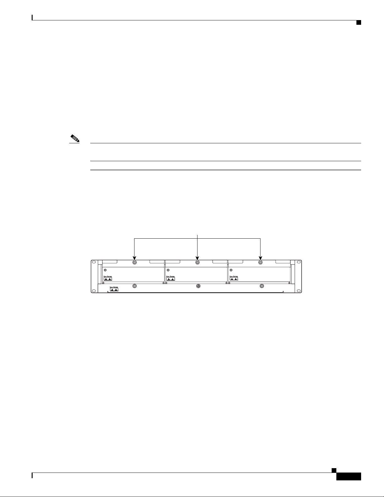
Chapter 3 Installing a Cisco 6130 with a POTS Splitter Configuration
Cisco 6100
Install the Third-Party POTS Splitter
Refer to the appropriate vendor documentation for installation procedures for the third-party
POTS splitter.
See Figure 1-1 for the correct placement of the third-party POTS splitter.
Install the Fan Tray
Complete the following steps to install the fan tray in the rack.
Note If you are using more than one Cisco 6130 chassis in a Cisco 6130 with a POTS splitter configuration,
you must install a fan tray under each chassis.
Step 1 Place the fan tray on a flat and stable surface (for example, a table top).
Step 2 Locate the first fan module and unscrew the thumbscrew that holds the fan module in place (the screw
at the top of each fan module), as shown in Figure 3-1.
Installation Procedures
Figure 3-1 Fan Tray Thumbscrews
thumbscrews
STATUS STATUS
Fan tray
STATUS
Cisco 6100
23717
OL-3768-01
Cisco 6130 with NI-2 Hardware Installation Guide
3-5
Page 86
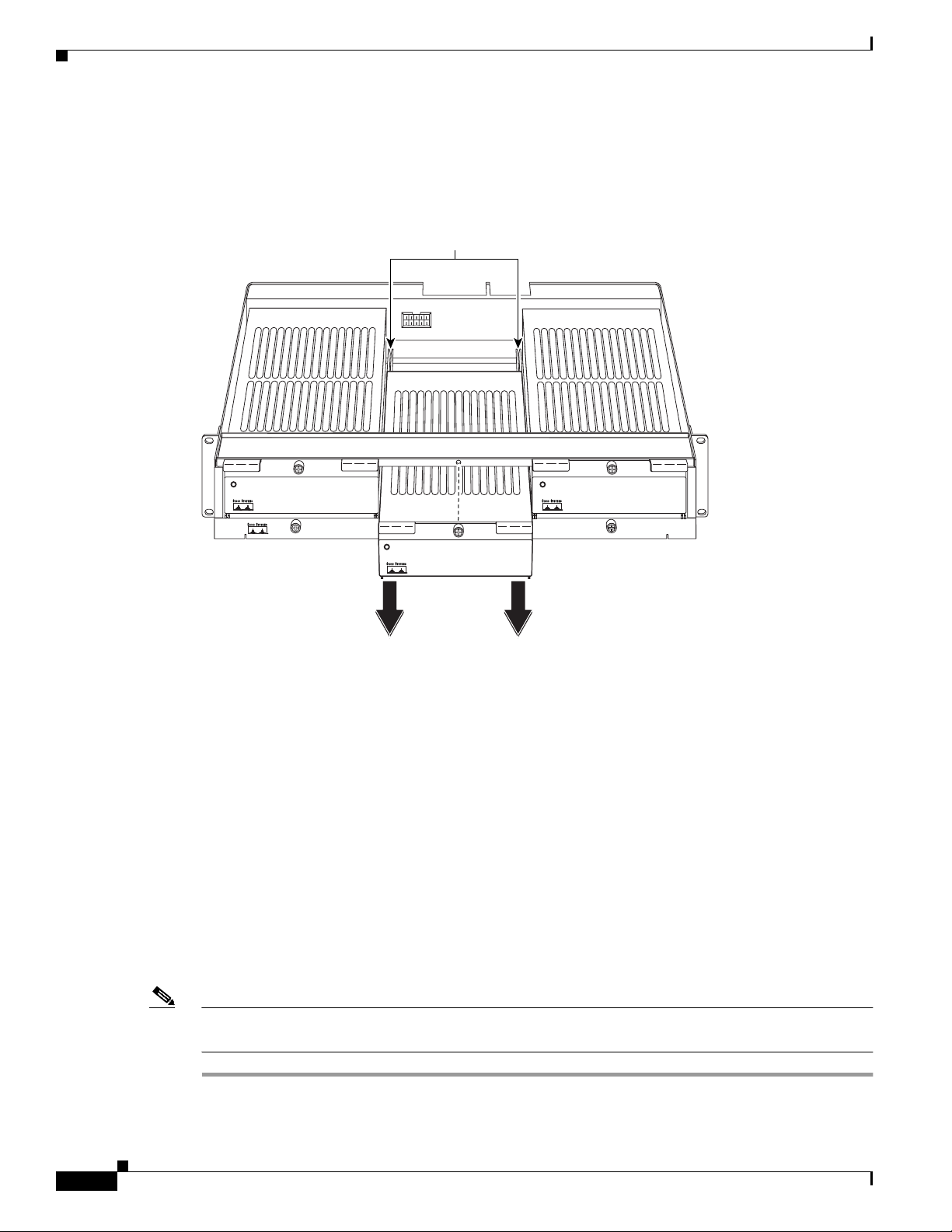
Installation Procedures
Cisco 6100
Step 3 Carefully remove the fan module by pulling it toward you. The fan module is located on slide rails for
Chapter 3 Installing a Cisco 6130 with a POTS Splitter Configuration
easy removal and installation. (See Figure 3-2.)
Figure 3-2 Removing the Fan Module from the Fan Tray
Fan tray
slide rails
Step 4
STATUS
STATUS
Place the fan module on a flat and stable surface (for example, a table top) until you are ready to reinsert
STATUS
23719
Cisco 6100
it into the fan tray.
Step 5 Repeat Step 2 through Step 4 for each fan module.
Step 6 Position the fan tray chassis, which occupies 2 RUs of space, above the POTS splitter.
Allow an additional 1 RU of space between the fan tray and the POTS splitter. This space allows for the
intake plenum.
Step 7 Use four mounting screws and a Phillips-head screwdriver to bolt the fan tray in the rack above the POTS
splitter. See Figure 1-1 for the correct placement of the fan tray.
Step 8 Align a fan module with the fan tray slide rails inside the fan tray.
Step 9 Slide the fan module into the fan tray.
Step 10 Tighten the thumbscrew above the fan module.
3-6
Step 11 Repeat Step 8 through Step 10 for each fan module.
Step 12 Repeat Step 1 through Step 11 for each fan tray.
Note For information about fan tray maintenance and air filter replacement, see Chapter 6, “Upgrading and
Maintaining the Cisco 6130 System.”
Cisco 6130 with NI-2 Hardware Installation Guide
OL-3768-01
Page 87

Chapter 3 Installing a Cisco 6130 with a POTS Splitter Configuration
Install the Cisco 6130 Chassis
Complete the following steps to install the Cisco 6130 chassis.
Installation Procedures
Warning
Note If the Cisco 6130 chassis ships with any line cards installed, verify that the chassis front cover is secure
Step 1 Position one Cisco 6130, which occupies 9 RUs of space, above the fan tray. The bottom of the
Step 2 Use four mounting screws and a Phillips-head screwdriver to bolt the Cisco 6130 chassis in the rack.
Step 3 Remove the chassis front cover.
Step 4 Repeat Step 1 through Step 3 for each Cisco 6130 chassis as necessary.
Two people are required to lift the chassis. Grasp the chassis underneath the lower edge and lift with
both hands. To prevent injury, keep your back straight and lift with your legs, not your back.
before lifting the chassis. The front cover prevents the line cards from falling out of the chassis.
Cisco 6130 should be flush with the top of the fan tray.
See Figure 1-1 for the correct placement of the Cisco 6130 chassis.
Install Blank Faceplates
Blank faceplates should occupy any empty slots in either the Cisco 6130 or Cisco 6120 chassis. The
blank faceplate installation is similar to the line card installation.
Complete the following steps to install the blank faceplates in the Cisco 6130 or Cisco 6120:
Step 1 Vertically align the blank faceplate edge with the top and bottom guides of the chassis slot.
Step 2 Lift up on the locking lever and gently apply pressure to the bottom of the faceplate while pushing the
blank faceplate into the slot.
Step 3 Push on the faceplate to fully seat the blank faceplate.
Step 4 Press down on the locking lever to secure the faceplate.
Step 5 Repeat Step 1 through Step 4 for each Cisco 6130 or Cisco 6120 chassis.
Ground the Cisco 6130, Fan Tray, and POTS Splitter
Warning
Note The grounding lug is not provided by Cisco. Use either a 5/8 inch or 3/4 inch lug to ground the
OL-3768-01
When installing the unit, the ground connection must always be made first and disconnected last.
Cisco 6130 chassis.
Cisco 6130 with NI-2 Hardware Installation Guide
3-7
Page 88

Installation Procedures
Step 1 Verify that power in the DC circuit is off.
Step 2 Remove all paint or oxidation from the rack at the point of the grounding connection.
Step 3 Measure enough wire to connect the Cisco 6130 to the rack. Use 12 American Wire Gauge [AWG] or
Tip Make sure your wire is only as long as needed to make the connection.
Step 4 Use a wire stripper to remove the casing from both ends of the wires.
Step 5 Use a 3/16-inch flat-head screwdriver to loosen the screw on the rack.
Step 6 Hook one end of the copper wire around the screw on the rack.
Step 7 Tighten the rack screw over the copper wire.
Step 8 Use a flat-head screwdriver to loosen the compression screw that is provided on the grounding lug of the
Chapter 3 Installing a Cisco 6130 with a POTS Splitter Configuration
Complete the following steps to connect the grounding lug on the Cisco 6130, fan tray, and POTS splitter
directly to the rack:
thicker (green or green with yellow stripes) stranded copper wire for the Cisco 6130 chassis grounding.
Use 14 AWG or thicker (green or green with yellow stripes) stranded copper wire for the fan tray and
POTS splitter grounding. (See Figure 3-3 for grounding wire location.)
Cisco 6130 chassis.
The grounding lugs are located in the upper left corner of each chassis (viewed from the rear), as shown
in Figure 3-3.
Step 9 Insert the other end of the copper wire under the compression screw.
Step 10 Tighten the compression screw over the copper wire.
Step 11 Repeat Step 1 through Step 10 for each Cisco 6130 chassis, fan tray, Cisco 6120, and third-party
POTS splitter.
Refer to the appropriate vendor documentation for grounding procedures for the third-party
POTS splitter.
Note Do not ground the components in a rack by chaining them together.
3-8
Cisco 6130 with NI-2 Hardware Installation Guide
OL-3768-01
Page 89
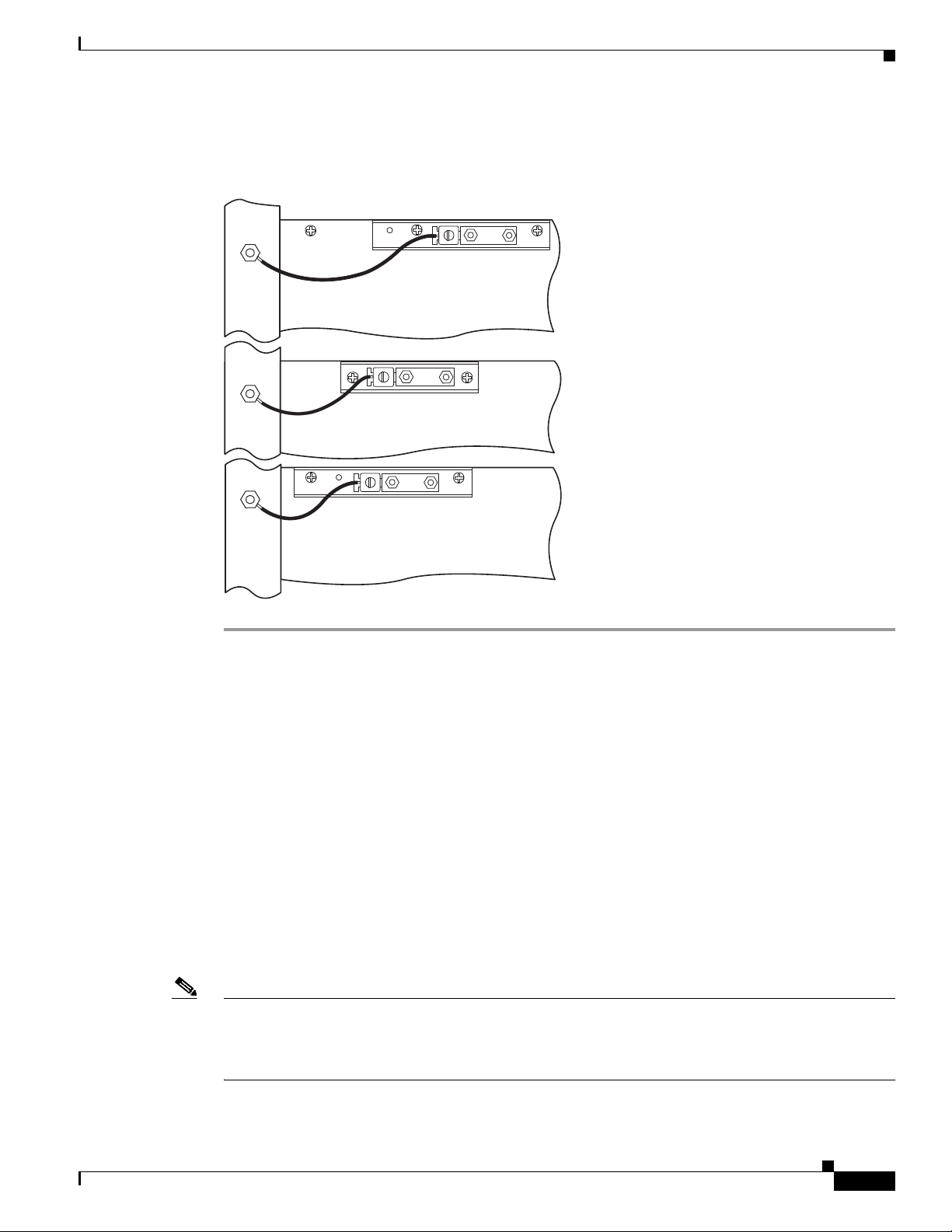
Chapter 3 Installing a Cisco 6130 with a POTS Splitter Configuration
The left side of Figure 3-3 shows how to ground the Cisco 6130, fan tray, and POTS splitter to the rack.
Figure 3-3 Grounding the Cisco 6130, Fan Tray, and POTS Splitter
Rack
Cisco 6130
Fan tray
Installation Procedures
Cisco 6120
54273
Connect the Cisco 6130 Chassis to the POTS Splitter
You can use the following POTS splitters in a Cisco 6130 with POTS splitter configuration:
• Cisco 6120
• Third-party POTS splitter
The following sections detail the cabling procedures to connect the Cisco 6130 to each POTS splitter.
These connections are for xDSL data flow between the Cisco 6130 and the POTS splitter.
Connect the Cisco 6130 to the Cisco 6120
Connect the one-to-two Champ cables (also called Y-cables) from each Cisco 6130 (connectors J39
through J44) to a Cisco 6120 (connectors J1 through J6). Table 3-2 shows the corresponding Cisco 6130
and Cisco 6120 connectors when two Cisco 6120 chassis are used.
Note If you are intermixing xTU-C line cards, see the “Intermixing Cables” section on page B-12 for cable
part numbers and cabling diagrams.
OL-3768-01
See the “Cisco 6130 to Cisco 6120 Cables” section on page B-3 for cable part numbers.
Cisco 6130 with NI-2 Hardware Installation Guide
3-9
Page 90
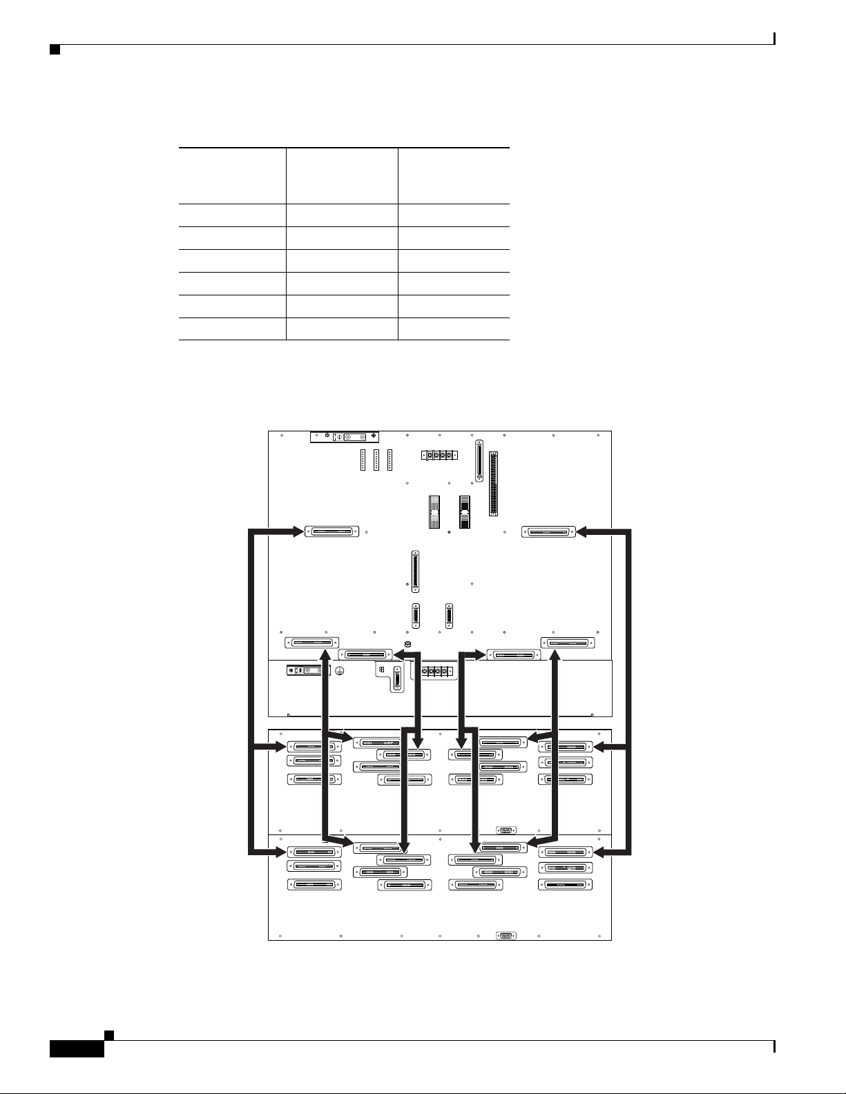
Installation Procedures
Chapter 3 Installing a Cisco 6130 with a POTS Splitter Configuration
Table 3-2 Cisco 6130 and Cisco 6120 Corresponding Connectors
Cisco 6130
Connector
First
Cisco 6120
Connector
Second
Cisco 6120
Connector
J39 J3 J3
J40 J1 J1
J41 J5 J5
J42 J4 J4
J43 J2 J2
J44 J6 J6
Figure 3-4 shows the cabling between one Cisco 6130 and two Cisco 6120 chassis.
Figure 3-4 Cisco 6130 to Two Cisco 6120 Chassis Cabling Diagram with One-to-Two Cables
J45
MODEM
POOL
A
-48V_B
-48RTN
-48RTN
P13
J48
-48V_A
OUT
P3P9
J39
Cisco 6130
J42
P14
P15
CRIT
MAJ
MIN
FAN
ALARM
E2A VISUAL AUDIBLE
P17
CRIT
CRIT
MAJ
MAJ
MIN
MIN
ACO
ACO
J46
MODEM
POOL
B
OUT
Fan tray
1st
Cisco 6120
2nd
Cisco 6120
J49
J43
J4
J4
J2
J8
J14
J2
J8
J14
FAN
J44
P2
ANALOG TEST I/F
P18
J1
P2
J1
J47
RING
TIP
RTN
-48VA
-48VB
J6
J10
J13
J6
J10
J13
J41
RTN
J5
J5
J40
J1
J9
J12
J36
J1
J9
J12
J36
J3
J7
J11
J3
J7
J11
54272
3-10
Cisco 6130 with NI-2 Hardware Installation Guide
OL-3768-01
Page 91

Chapter 3 Installing a Cisco 6130 with a POTS Splitter Configuration
Note For additional information about the Cisco 6120 backplane connectors, see the “Cisco 6120 Backplane”
section on page 1-35.
Connect the Cisco 6130 to the Third-Party POTS Splitter
Use the cables described in the “Cisco 6130 to Third-Party POTS Splitter Cables” section on page B-5
to cable each Cisco 6130 to a third-party POTS splitter. Refer to the appropriate vendor documentation
for cabling procedures for the third-party POTS splitter.
Attach Cisco 6130 Power Connections
Caution To prevent the system from powering up, do not install the fuses at this time. If the fuses are already
installed in the fuse and alarm panel, remove them. You can replace the fuses after the system is installed
and connected.
Installation Procedures
External power is supplied to the system as –48V DC from the central office (CO) power source or
rectifier to the fuse and alarm panel. Power is fed from the fuse and alarm panel to the Cisco 6130 chassis
by a terminal block connector with four dual-power connections (P13) located at the top of the
chassis backplane. Figure 3-5 shows the location of the power connection (P13) on the chassis.
Note The fuse and alarm panel and wires are not provided by Cisco.
OL-3768-01
Cisco 6130 with NI-2 Hardware Installation Guide
3-11
Page 92
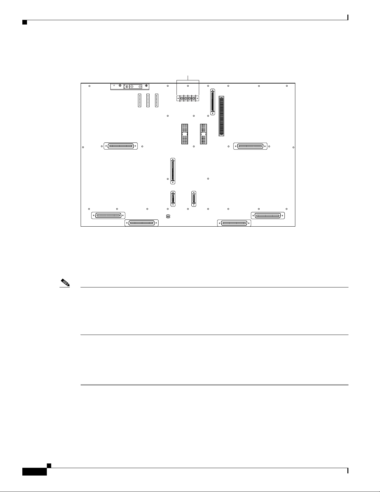
Installation Procedures
Chapter 3 Installing a Cisco 6130 with a POTS Splitter Configuration
Figure 3-5 Cisco 6130 Power Connection Locations
Power
connections
J45
MODEM
P14
P15
CRIT
MAJ
MIN
FAN
ALARM
E2A VISUAL AUDIBLE
P17
CRIT
CRIT
MAJ
MAJ
MIN
MIN
ACO
ACO
-48V_B
-48RTN
P13
POOL
A
OUT
-48RTN
-48V_A
J48
J42
J39
P3P9
J46
MODEM
POOL
B
OUT
J43
J44
ANALOG TEST I/F
P18
RING
TIP
J49
J47
J40
J41
18374
You can wire the power connections from the Cisco 6130 to the fuse and alarm panel for either dual- or
single-power feed:
• “Attach Cisco 6130 Power Connections for a Dual-Power Feed” section on page 3-12
• “Attach Cisco 6130 Power Connections for a Single-Power Feed” section on page 3-15
Note Connect each Cisco 6130 with NI-2 system component to a separate fuse. Do not power the components
in the rack by chaining them together.
See Chapter 2, “Preparing for Installation” for the calculation tables that are necessary to determine the
minimum fuse rating for each component that is wired to the fuse and alarm panel. Refer to the power
rating label on the back of the Cisco 6130 to determine the maximum fuse rating.
Attach Cisco 6130 Power Connections for a Dual-Power Feed
Complete the following steps to attach the Cisco 6130 power connections (P13) to the fuse and alarm
panel for a dual-power feed:
Step 1 Use a socket driver or a Phillips-head screwdriver to remove the clear cover over the Cisco 6130
power connections.
Step 2 Measure enough wire (12 AWG black and red copper solid or stranded wire) to connect each of the
Cisco 6130 power input connections to the fuse and alarm panel.
Cisco 6130 with NI-2 Hardware Installation Guide
3-12
OL-3768-01
Page 93
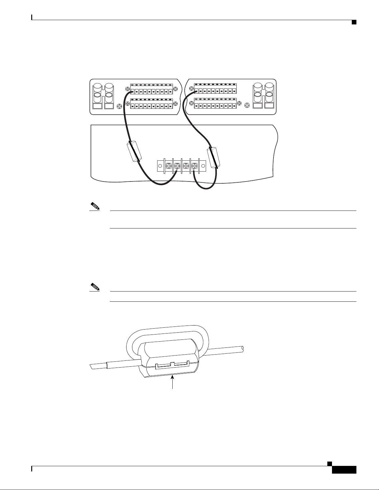
Chapter 3 Installing a Cisco 6130 with a POTS Splitter Configuration
Figure 3-6 shows the Cisco 6130 power input connections wired to the fuse and alarm panel.
Figure 3-6 Power Input Connections for the Cisco 6130—Dual-Power Feed
Installation Procedures
12345678910
NEG DC
12345678910
POS RTN
A
NEG
POS
NEG
POS
12345678910
NEG DC
12345678910
B
POS RTN
P13
-48V_A
-48V_B
-48RTN
-48RTN
Cisco 6130
Note Figure 3-6 shows the wires looped through a ferrite. If you use thicker wire, it will not be
necessary to loop the wire through the ferrite.
Step 3 Use a wire stripper to remove the casing from both ends of the wires.
Step 4 Use a Phillips-head screwdriver to attach a wire to the –48V_A power input connection on the
Cisco 6130 (P13).
54268
Step 5 Loop the wire through the ferrite as shown in Figure 3-7. If you use thicker wire, it will not be necessary
to loop the wire through the ferrite.
Note Looping the wire secures the ferrite.
Figure 3-7 Wire Looped through Ferrite
18375
Ferrite
Step 6
Attach the wire to a fuse and alarm panel NEG (negative) DC connector.
Step 7 Use a Phillips-head screwdriver to attach a wire to the –48V_B power input connection on the
Cisco 6130 (P13).
OL-3768-01
Cisco 6130 with NI-2 Hardware Installation Guide
3-13
Page 94
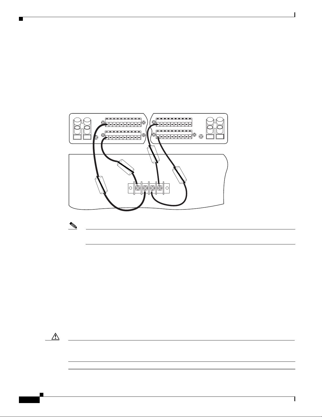
Installation Procedures
Step 8 Loop the wire through the ferrite as shown in Figure 3-7. If you use thicker wire, it will not be necessary
Step 9 Attach the wire to a fuse and alarm panel NEG DC connector.
Step 10 Measure enough wire (12 AWG black and red copper solid or stranded wire) to connect each of the
Chapter 3 Installing a Cisco 6130 with a POTS Splitter Configuration
to loop the wire through the ferrite.
Cisco 6130 power return connections to the fuse and alarm panel.
Figure 3-8 shows the Cisco 6130 power return connections wired to the fuse and alarm panel for a
dual-power feed.
Figure 3-8 Power Return Connections for the Cisco 6130—Dual-Power Feed
12345678910
NEG DC
12345678910
POS RTN
A
NEG
POS
NEG
POS
12345678910
NEG DC
12345678910
B
POS RTN
P13
-48V_A
-48V_B
-48RTN
-48RTN
Cisco 6130
Note Figure 3-8 shows the wires looped through a ferrite. If you use thicker wire, it will not be
necessary to loop the wire through the ferrite.
Step 11 Use a wire stripper to remove the casing from both ends of the wires.
Step 12 Use a Phillips-head screwdriver to attach a wire to a –48V power return connection (–48RTN) on the
Cisco 6130 (P13).
54269
3-14
Step 13 Loop the wire through the ferrite as shown in Figure 3-7. If you use thicker wire, it will not be necessary
to loop the wire through the ferrite.
Step 14 Attach the wire to a fuse and alarm panel POS (positive) RTN connector.
Step 15 Repeat Step 10 through Step 14 for the remaining –48V power return connection (–48RTN).
Step 16 Use a socket driver or a Phillips-head screwdriver to attach the clear cover over the Cisco 6130
power connections.
Step 17 Repeat Step 1 through Step 16 each Cisco 6130 chassis that is to be connected to a dual-power feed.
Caution To prevent the system from powering up, do not install the fuses at this time. If the fuses are already
installed in the fuse and alarm panel, remove them. You can replace the fuses after the system is installed
and connected.
Cisco 6130 with NI-2 Hardware Installation Guide
OL-3768-01
Page 95
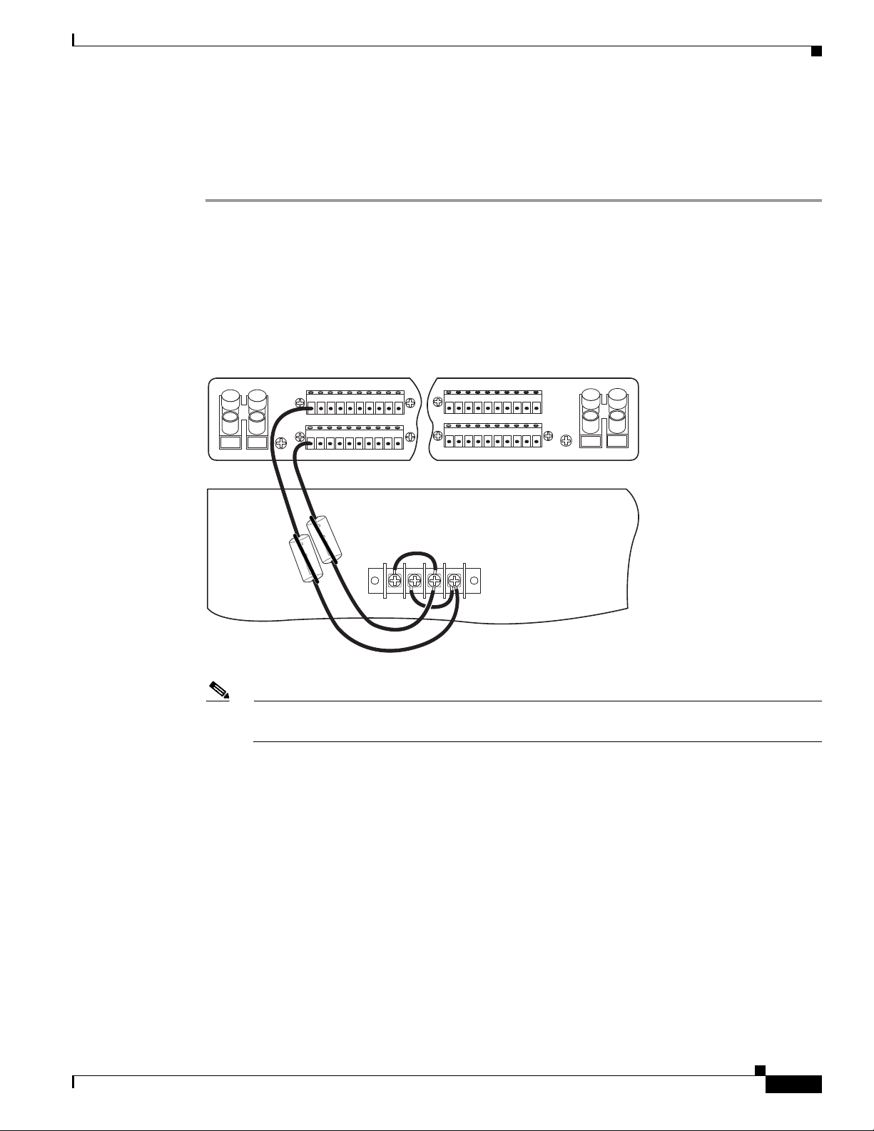
Chapter 3 Installing a Cisco 6130 with a POTS Splitter Configuration
Attach Cisco 6130 Power Connections for a Single-Power Feed
Complete the following steps to attach the Cisco 6130 power connections (P13) to the fuse and alarm
panel for a single-power feed:
Step 1 Use a socket driver or a Phillips-head screwdriver to remove the clear cover over the Cisco 6130
power connections.
Step 2 Measure enough wire (12 AWG black and red copper solid or stranded wire) to connect each of the
Cisco 6130 power connections to the fuse and alarm panel.
Figure 3-9 shows the Cisco 6130 power connections wired to the fuse and alarm panel for a
single-power feed.
Figure 3-9 Power Connections for the Cisco 6130—Single-Power Feed
Installation Procedures
12345678910
NEG DC
12345678910
POS RTN
A
NEG
POS
NEG
POS
12345678910
NEG DC
12345678910
B
POS RTN
P13
-48V_A
-48V_B
-48RTN
-48RTN
Cisco 6130
Note Figure 3-9 shows the wires looped through a ferrite. If you use thicker wire, it will not be
necessary to loop the wire through the ferrite.
Step 3 Use a wire stripper to remove the casing from both ends of the wires.
Step 4 Use a Phillips-head screwdriver, to attach a wire to the –48V_A power input connection on the
Cisco 6130 (P13).
54270
OL-3768-01
Cisco 6130 with NI-2 Hardware Installation Guide
3-15
Page 96
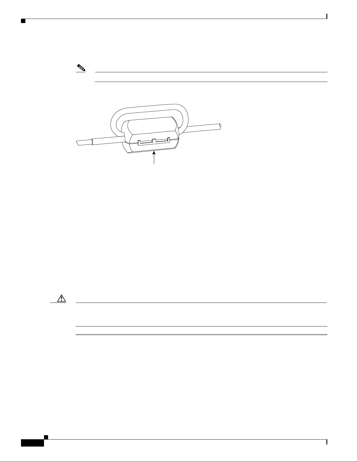
Installation Procedures
Step 5 Loop the wire through the ferrite as shown in Figure 3-10. If you use thicker wire, it will not be necessary
Step 6 Attach the wire to the fuse and alarm panel NEG DC connector.
Chapter 3 Installing a Cisco 6130 with a POTS Splitter Configuration
to loop the wire through the ferrite.
Note Looping the wire secures the ferrite.
Figure 3-10 Wire Looped through Ferrite
18375
Ferrite
Step 7 Use a Phillips-head screwdriver to attach a wire to a –48RTN power return connection on the Cisco 6130
(P13). See Figure 3-9 for correct placement.
Step 8 Loop the wire through the ferrite as shown in Figure 3-10. If you use thicker wire, it will not be necessary
to loop the wire through the ferrite.
Step 9 Attach the wire to the fuse and alarm panel POS RTN connector. See Figure 3-9 for correct placement.
Step 10 Use a Phillips-head screwdriver to attach a wire to connect the –48V_A and –48V_B power input
connections to each other.
Step 11 Use a Phillips-head screwdriver to attach a wire to connect the –48RTN power return connections to
each other.
Step 12 Use a socket driver or a Phillips-head screwdriver to attach the clear cover over the Cisco 6130
power connections.
Step 13 Repeat Step 1 through Step 12 for each Cisco 6130 chassis that is to be connected to a single-power feed.
Caution To prevent the system from powering up, do not install the fuses at this time. If the fuses are already
installed in the fuse and alarm panel, remove them. You can replace the fuses after the system is installed
and connected.
3-16
Cisco 6130 with NI-2 Hardware Installation Guide
OL-3768-01
Page 97
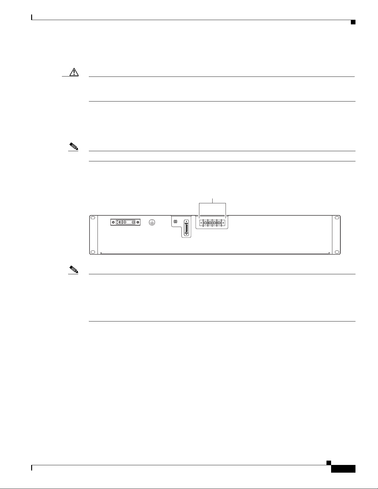
Chapter 3 Installing a Cisco 6130 with a POTS Splitter Configuration
Attach Fan Tray Power Connections
Caution To prevent the system from powering up, do not install the fuses at this time. If the fuses are already
installed in the fuse and alarm panel, remove them. You can replace the fuses after the system is installed
and connected.
External power is supplied to the system as –48V DC from the CO power source or rectifier to the fuse
and alarm panel. Power is fed from the fuse and alarm panel to the fan tray by a terminal block connector
with four dual power connections (P1) located at the top of the fan tray backplane. Figure 3-11 shows
the location of the power connection (P1) on the fan tray.
Note The fuse and alarm panel and wires are not provided by Cisco.
Figure 3-11 Fan Tray Power Connection Location
Installation Procedures
Power
connections
_
FAN
J1
+
P2
P2
J1
-48V RTN
-48V RTN
P1
RTN
RTN
-48VA
-48VB
26379
Note Connect each Cisco 6130 with NI-2 system component to a separate fuse. Do not power the components
in the rack by chaining them together.
See Chapter 2, “Preparing for Installation” for the calculation tables that are necessary to determine the
minimum fuse rating for each component that is wired to the fuse and alarm panel. Refer to the label on
the back of the fan tray to determine the maximum fuse rating.
You can wire the power connections from the fuse and alarm panel to the fan tray for either dual- or
single-power feed:
• “Attach Fan Tray Power Connections for a Dual-Power Feed” section on page 3-18
• “Attach Fan Tray Power Connections for a Single-Power Feed” section on page 3-19
OL-3768-01
Cisco 6130 with NI-2 Hardware Installation Guide
3-17
Page 98
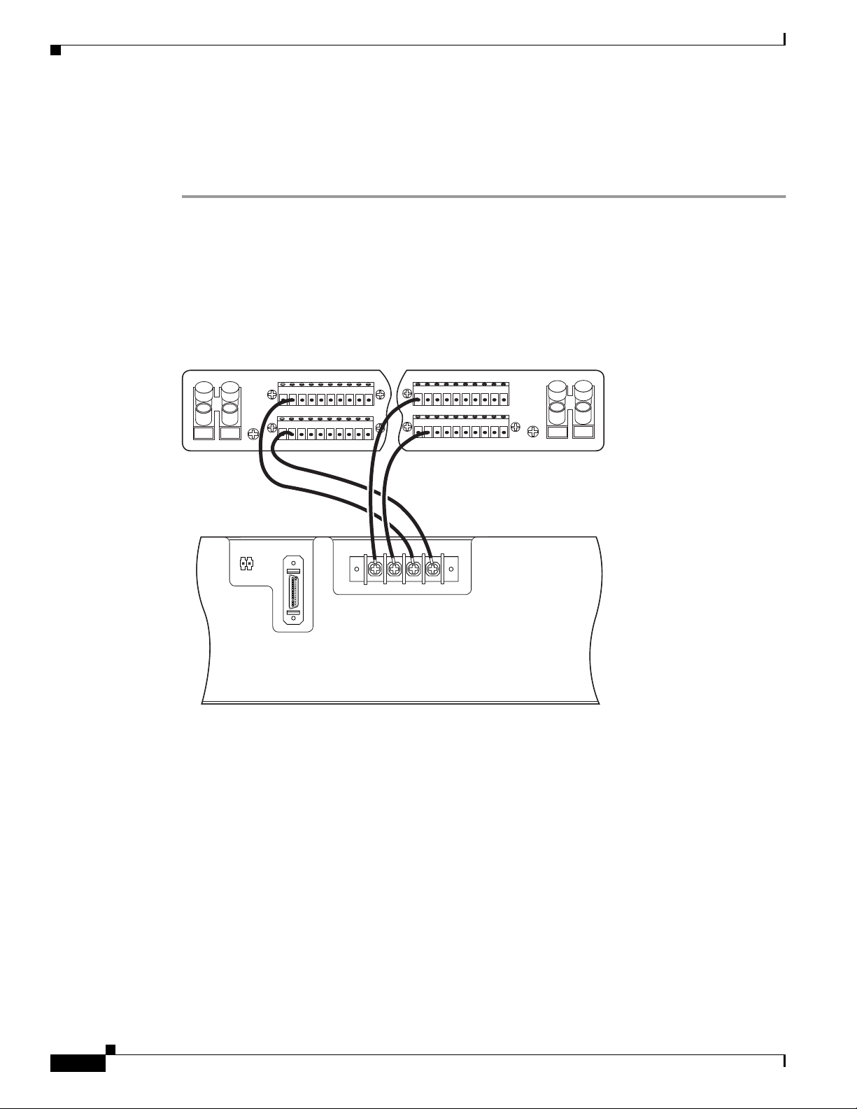
Chapter 3 Installing a Cisco 6130 with a POTS Splitter Configuration
Installation Procedures
Attach Fan Tray Power Connections for a Dual-Power Feed
Complete the following steps to attach the fan tray power connections to the fuse and alarm panel for a
dual-power feed:
Step 1 Use a socket driver or a Phillips-head screwdriver to remove the clear cover over the fan tray
power connections.
Step 2 Measure enough wire (14 to 18 AWG copper solid or stranded wire) to connect each of the fan tray power
connections to the fuse and alarm panel.
Figure 3-12 shows the power connections from the fan tray to the fuse and alarm panel for a
dual-power feed.
Figure 3-12 Power Connections for the Fan Tray—Dual-Power Feed
12345678910
12345678910
-48V RTN
RTN
-48VA
-48VB
NEG DC
POS RTN
RTN
A
NEG
POS
26376
Step 3
12345678910
NEG DC
12345678910
B
NEG
POS
_
FAN
P2
POS RTN
J1
+
P2
J1
-48V RTN
P1
Fan tray
Use a wire stripper to remove the casing from both ends of the wires.
Step 4 Use a Phillips-head screwdriver to attach a wire to the –48VA power input connection on the fan
tray (P1).
3-18
Step 5 Attach the wire to the fuse and alarm panel NEG DC connector. See Figure 3-12 for correct placement.
Step 6 Use a Phillips-head screwdriver to attach a wire to the –48VB power input connection on the fan
tray (P1).
Step 7 Attach the wire to the fuse and alarm panel NEG DC connector. See Figure 3-12 for correct placement.
Step 8 Use a Phillips-head screwdriver to attach a wire to an RTN power return connection on the fan tray (P1).
Step 9 Attach the wire to a fuse and alarm panel POS RTN connector.
Step 10 Repeat Step 8 and Step 9 for the remaining RTN power return connection.
Cisco 6130 with NI-2 Hardware Installation Guide
OL-3768-01
Page 99
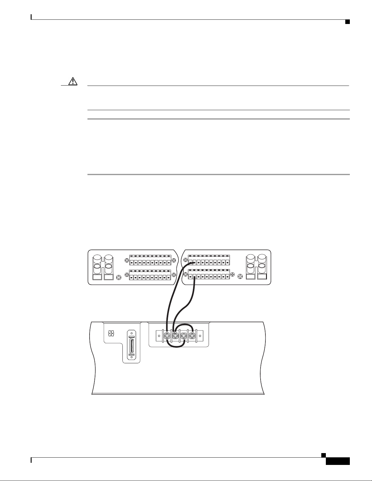
Chapter 3 Installing a Cisco 6130 with a POTS Splitter Configuration
Step 11 Use a socket driver or a Phillips-head screwdriver to attach the clear cover over the fan tray
power connections.
Step 12 Repeat Step 1 through Step 11 for each fan tray.
Caution To prevent the system from powering up, do not install the fuses at this time. If the fuses are already
installed in the fuse and alarm panel, remove them. You can replace the fuses after the system is installed
and connected.
Attach Fan Tray Power Connections for a Single-Power Feed
Complete the following steps to attach the fan tray power connections to the fuse and alarm panel for a
single-power feed:
Step 1 Use a socket driver or a Phillips-head screwdriver to remove the clear cover over the fan tray
power connections.
Step 2 Measure enough wire (14 to 18 AWG copper solid or stranded wire) to connect each of the fan tray power
connections to the fuse and alarm panel.
Installation Procedures
Figure 3-13 shows the power connections from the fan tray to the fuse and alarm panel for a
single-power feed.
Figure 3-13 Power Connections for the Fan Tray—Single-Power Feed
12345678910
12345678910
RTN
-48V RTN
RTN
-48VA
NEG DC
POS RTN
RTN
A
NEG
POS
26377
NEG
POS
_
Fan tray
+
FAN
P2
12345678910
NEG DC
12345678910
B
POS RTN
J1
P2
J1
-48V
P1
-48VB
OL-3768-01
Step 3
Use a wire stripper to remove the casing from both ends of the wires.
Step 4 Use a Phillips-head screwdriver to attach a wire to the –48VA power input connection on the fan
tray (P1).
Cisco 6130 with NI-2 Hardware Installation Guide
3-19
Page 100

Installation Procedures
Step 5 Attach the wire to the fuse and alarm panel NEG DC connector.
Step 6 Use a Phillips-head screwdriver to attach a wire to an RTN power return connection on the fan tray (P1).
Step 7 Attach the wire to the fuse and alarm panel POS RTN connector. See Figure 3-13 for correct placement.
Step 8 Use a Phillips-head screwdriver to attach a wire to connect the –48VA and –48VB power input
Step 9 Use a Phillips-head screwdriver to attach a wire to connect the RTN power return connections to
Step 10 Use a socket driver or a Phillips-head screwdriver to attach the clear cover over the fan tray
Step 11 Repeat Step 1 through Step 10 for each fan tray.
Caution To prevent the system from powering up, do not install the fuses at this time. If the fuses are already
Chapter 3 Installing a Cisco 6130 with a POTS Splitter Configuration
See Figure 3-13 for correct placement.
connections to each other.
each other.
power connections.
installed in the fuse and alarm panel, remove them. You can replace the fuses after the system is installed
and connected.
Locate or Install the System I/O Card
The Cisco 6130 chassis should ship with the system I/O card already installed on the chassis backplane.
The system I/O card is attached to backplane connectors P3 and P9, two 2-mm hard metric (HM)
module connectors.
Caution To prevent the system from powering up, do not install the fuses at this time. If the fuses are already
installed in the fuse and alarm panel, remove them. You can replace the fuses after the system is installed
and connected.
3-20
Cisco 6130 with NI-2 Hardware Installation Guide
OL-3768-01
 Loading...