

Page 1

A Sierra Monitor Company
Driver Manual
(Supplement to the FieldServer Instruction Manual)
FS-8700-42 Spectronics
APPLICABILITY & EFFECTIVITY
Effective for all systems manufactured after May 1, 2001
Driver Version: 1.00
Document Revision: 4
Page 2

FS-8700-42_Spectronics Driver Manual Table of Contents
Table of Contents
1. Spectronics Description .....................................................................................................3
2. Driver Scope of Supply.......................................................................................................4
2.1. Supplied by FieldServer Technologies for this driver .....................................................4
2.2. Provided by Supplier of 3rd Party Equipment..................................................................4
3. Hardware Connections........................................................................................................5
4. Configuring the FieldServer as a Spectronics Client.......................................................6
4.1. Data Arrays/Descriptors .................................................................................................6
4.2. Client Side Connection Descriptors................................................................................7
4.3. Client Side Node Descriptors .........................................................................................7
4.4. Client Side Map Descriptors ...........................................................................................8
4.4.1. FieldServer Related Map Descriptor Parameters....................................................8
4.4.2. Driver Related Map Descriptor Parameters ............................................................8
4.4.3. Timing Parameters..................................................................................................8
4.4.4. Map Descriptor Example.........................................................................................9
5. Configuring the FieldServer as a Spectronics Server....................................................10
5.1. Server Side Connection Descriptors ............................................................................10
5.2. Server Side Node Descriptors ......................................................................................11
5.3. Server Side Map Descriptors........................................................................................ 11
5.3.1. FieldServer Specific Map Descriptor Parameters..................................................11
5.3.2. Driver Specific Map Descriptor Parameters ..........................................................11
5.3.3. Map Descriptor Example.......................................................................................12
Appendix A. Advanced Topics – Spectronics ....................................................................13
Appendix A.1. Default Data Types........................................................................................13
Appendix A.2. Single Writes ................................................................................................. 13
Appendix A.3. Write-Thru Operation.....................................................................................13
Appendix A.4. Connection to York Modbus Microgateway...................................................14
FieldServer Technologies 1991 Tarob Court Milpitas, California 95035 USA Web:www.fieldserver.com
Tel: (408) 262-2299 Fax: (408) 262-9042 Toll_Free: 888-509-1970 email: support@fieldserver.com
Page 3

FS-8700-42_Spectronics Driver Manual Page 3 of 15
1. Spectronics Description
The Spectronics driver allows the FieldServer to transfer data to and from devices over either
RS-232 or RS-485 using Spectronics protocol. The FieldServer can emulate either a Server or
Client.
The information that follows describes how to expand upon the factory defaults provided in the
configuration files included with the FieldServer.
FieldServer Technologies 1991 Tarob Court Milpitas, California 95035 USA Web:www.fieldserver.com
Tel: (408) 262-2299 Fax: (408) 262-9042 Toll_Free: 888-509-1970 email: support@fieldserver.com
Page 4
FS-8700-42_Spectronics Driver Manual Page 4 of 15
2. Driver Scope of Supply
2.1. Supplied by FieldServer Technologies for this driver
FieldServer Technologies
PART #
FS-8915-10 7’ Patch Cable
FS-8917-01 RJ45 to DB25M connector adapter
FS-8700-01 Driver Manual
Description
2.2. Provided by Supplier of 3rd Party Equipment
PART # DESCRIPTION
Spectronics Device
FieldServer Technologies 1991 Tarob Court Milpitas, California 95035 USA Web:www.fieldserver.com
Tel: (408) 262-2299 Fax: (408) 262-9042 Toll_Free: 888-509-1970 email: support@fieldserver.com
Page 5
FS-8700-42_Spectronics Driver Manual Page 5 of 15
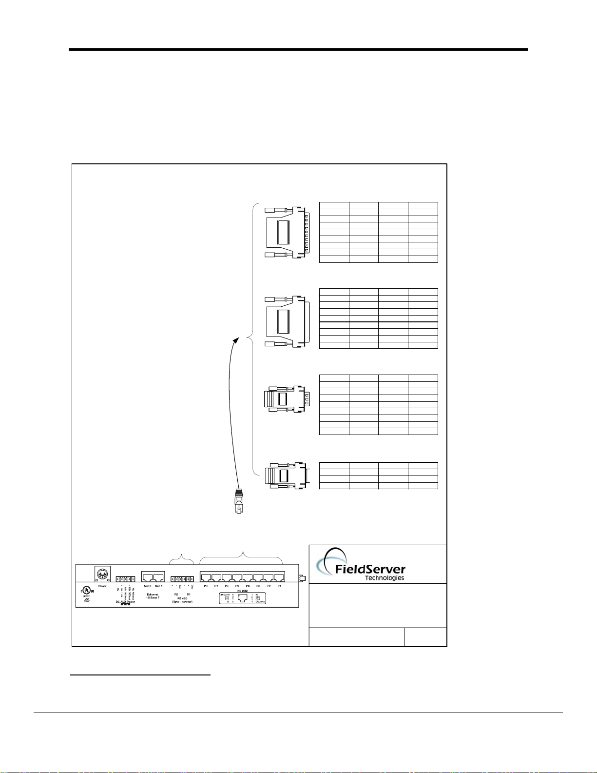
3. Hardware Connections
It is possible to connect a Spectronics device to any of the existing serial ports on the
FieldServer
1
. These ports simply need to be configured for Spectronics in the configuration file.
Configure the Spectronics device according to manufacturer’s instructions.
8917-01 WIRE LIST
RX RJ45-01 DB25M-03 WHITE
CTS RJ45-02 DB25M-05 BROWN
DSR RJ45-03 YELLOW
GND RJ45-04 DB25M-07 GREEN
GND RJ45-05 RED
DTR RJ45-06 BLACK
RTS RJ45-07 DB25M-04 ORANGE
TX RJ45-08 DB25M-02 BLUE
8917-04 WIRE LIST
RX RJ45-01 DB25F-02 WHITE
CTS RJ45-02 DB25F-04 BROWN
DSR RJ45-03 YELLOW
GND RJ45-04 DB25F-07 GREEN
GND RJ45-05 RED
DTR RJ45-06 BLACK
RTS RJ45-07 DB25F-05 ORANGE
TX RJ45-08 DB25F-03 BLUE
8917-03 WIRE LIST
RX RJ45-01 DB9M-0 2 GREY
CTS RJ45-02 DB9M08 BROWN
DSR RJ45-03 DB9M-06 YELLOW
GND RJ45-04 DB9M-05 GREEN
GND RJ45-05 RED
DTR RJ45-06 DB9M-04 BLACK
RTS RJ45-07 DB9M-07 ORANGE
TX RJ45-08 DB9M-03 BLUE
Typical DB9/DB25
kit assemblies are
shown here. Refer
to the third party
device literature
for exact
configuration
required.
DB25M
DB25F
DB9M
FUNCTION FROM TO COLOUR
FUNCTION FROM TO COLOUR
FUNCTION FROM TO COLOUR
DB9F
RJ45 Connector
OR
RS-485
network
Connect
to 2-wire
EIA232
RJ45 to
Connector
FUNCTION FROM TO COLOUR
8917-02 WIRE LIST
Rx RJ45-01 DB9F-03 WHITE
GND RJ45-04 DB9F-05 GREEN
Tx RJ45-08 DB9F-02 BLUE
(408)-262-2299
FIELDSERVER
MODBUS RTU
CONNECTION DIAGRAM
BASE NAME:
FILE NAME:
1
Not all ports shown are necessarily supported by the hardware. Consult the appropriate Instruction
DATE: 4/20/04
BY: MC
manual for details of the ports available on specific hardware.
FieldServer Technologies 1991 Tarob Court Milpitas, California 95035 USA Web:www.fieldserver.com
Tel: (408) 262-2299 Fax: (408) 262-9042 Toll_Free: 888-509-1970 email: support@fieldserver.com
Page 6

FS-8700-42_Spectronics Driver Manual Page 6 of 15
4. Configuring the FieldServer as a Spectronics Client
For a detailed discussion on FieldServer configuration, please refer to the FieldServer
Configuration Manual. The information that follows describes how to expand upon the factory
defaults provided in the configuration files included with the FieldServer (See “.csv” sample files
provided with the FS).
This section documents and describes the parameters necessary for configuring the FieldServer
to communicate with a Spectronics Server.
4.1. Data Arrays/Descriptors
The configuration file tells the FieldServer about its interfaces, and the routing of data
required. In order to enable the FieldServer for Spectronics communications, the driver
independent FieldServer buffers need to be declared in the “Data Arrays” section, the
destination device addresses need to be declared in the “Client Side Nodes” section, and
the data required from the servers needs to be mapped in the “Client Side Map Descriptors”
section. Details on how to do this can be found below.
Note that in the tables, * indicates an optional parameter, with the bold legal value being the
default.
Section Title
Data_Arrays
Column Title Function Legal Values
Data_Array_Name Provide name for Data Array
Provide data format. Each
Data_Array_Format
Data_Array_Length
Example
// Data Arrays
Data_Arrays
Data_Array_Name, Data_Format, Data_Array_Length
DA_AI_01, UInt16, 200
DA_AO_01, UInt16, 200
DA_DI_01, Bit, 200
DA_DO_01, Bit, 200
Data Array can only take on
one format.
Number of Data Objects. Must
be larger than the data
storage area required by the
map descriptors for the data
being placed in this array.
Up to 15 alphanumeric
characters
FLOAT, BIT, UInt16, SInt16,
Packed_Bit, Byte,
Packed_Byte, Swapped_Byte
1-10,000
FieldServer Technologies 1991 Tarob Court Milpitas, California 95035 USA Web:www.fieldserver.com
Tel: (408) 262-2299 Fax: (408) 262-9042 Toll_Free: 888-509-1970 email: support@fieldserver.com
Page 7

FS-8700-42_Spectronics Driver Manual Page 7 of 15
4.2. Client Side Connection Descriptors
Section Title
Connections
Column Title Function Legal Values
Port
Baud* Specify baud rate
Parity* Specify parity None (Vendor limitation)
Data_Bits*
Stop_Bits*
Protocol
Handshaking* Specify hardware handshaking RTS, RTS/CTS, None
Poll Delay*
Example
// Client Side Connections
Connections
Port, Protocol, Baud, Parity, Handshaking, Poll_Delay
P8, Spectronics, 9600, None, None, 0.100s
Specify which port the device is connected
to the FieldServer
P1-P8, R1-R22
110 – 115200, standard baud
rates only
Specify data bits 8 (Vendor limitation)
Specify stop bits 1 (Vendor limitation)
Specify protocol used Spectronics
Time between internal polls 0-32000 s, 1 s
4.3. Client Side Node Descriptors
Section Title
Nodes
Column Title Function Legal Values
Node_Name Provide name for node
Node_ID
Station address of physical server
node
Protocol Specify protocol used Spectronics
Port
Specify which port the device is
connected to the FieldServer
Example:
// Client Side Nodes
Nodes
Node_Name, Node_ID, Protocol, Port
Spec_device1, 1, Spectronics, P8
2
Not all ports shown are necessarily supported by the hardware. Consult the appropriate Instruction
manual for details of the ports available on specific hardware.
Up to 32 alphanumeric
characters
1-255
P1-P8, R1-R2
2
FieldServer Technologies 1991 Tarob Court Milpitas, California 95035 USA Web:www.fieldserver.com
Tel: (408) 262-2299 Fax: (408) 262-9042 Toll_Free: 888-509-1970 email: support@fieldserver.com
Page 8

FS-8700-42_Spectronics Driver Manual Page 8 of 15
4.4. Client Side Map Descriptors
4.4.1. FieldServer Related Map Descriptor Parameters
Column Title Function Legal Values
Map_Descriptor_Name
Data_Array_Name
Data_Array_Offset
Function
Name of this Map
Descriptor
Name of Data Array
where data is to be
stored in the
FieldServer
Starting location in Data
Array
Function of Client Map
Descriptor
Up to 32 alphanumeric
characters
One of the Data Array
names from “Data Array”
section above
0 to maximum specified in
“Data Array” section above
RDBC
4.4.2. Driver Related Map Descriptor Parameters
Column Title Function Legal Values
Node_Name
Length Length of Map Descriptor 1-125 (Register,AI)
Address
Data_Array_Low_Scale* Scaling zero in Data Array
Data_Array_High_Scale* Scaling max in Data Array
Node_Low_Scale*
Node_High_Scale*
Name of Node to fetch
data from
Starting address of read
block
Scaling zero in Connected
Node
Scaling max in Connected
Node
One of the node names
specified in “Client Node
Descriptor” above
40001, 30001, etc
-2,147,483,648 to
2,147,483,647, 0
-2,147,483,648 to
2,147,483,647, 100
-2,147,483,648 to
2,147,483,647, 0
-2,147,483,648 to
2,147,483,647, 100
4.4.3. Timing Parameters
Column Title Function Legal Values
Scan_Interval Rate at which data is polled ≥0.001s
FieldServer Technologies 1991 Tarob Court Milpitas, California 95035 USA Web:www.fieldserver.com
Tel: (408) 262-2299 Fax: (408) 262-9042 Toll_Free: 888-509-1970 email: support@fieldserver.com
Page 9

FS-8700-42_Spectronics Driver Manual Page 9 of 15
4.4.4. Map Descriptor Example.
// Client Side Map Descriptors
Map_Descriptors
Map_Descriptor_Name, Data_Array_Name, Data_Array_Offset, Function, Node_Name, Address, Length, Scan_Interval
CMD_AI_01, DA_AI_01, 0, RDBC, Spec_Device1, 30001, 20, 1.000s
CMD_AO_01, DA_AO_01, 0, RDBC, Spec_Device1, 40001, 20, 1.000s
CMD_DI_01, DA_DI_01, 0, RDBC, Spec_Device1, 10001, 20, 1.000s
CMD_DO_01, DA_DO_01, 0, RDBC, Spec_Device1, 00001, 20, 1.000s
FieldServer Technologies 1991 Tarob Court Milpitas, California 95035 USA Web:www.fieldserver.com
Tel: (408) 262-2299 Fax: (408) 262-9042 Toll_Free: 888-509-1970 email: support@fieldserver.com
Page 10

FS-8700-42_Spectronics Driver Manual Page 10 of 15
5. Configuring the FieldServer as a Spectronics Server
For a detailed discussion on FieldServer configuration, please refer to the FieldServer
Configuration Manual. The information that follows describes how to expand upon the factory
defaults provided in the configuration files included with the FieldServer (See “.csv” sample files
provided with the FieldServer).
This section documents and describes the parameters necessary for configuring the FieldServer
to communicate with a Spectronics Client.
The configuration file tells the FieldServer about its interfaces, and the routing of data required.
In order to enable the FieldServer for Spectronics communications, the driver independent
FieldServer buffers need to be declared in the “Data Arrays” section, the FieldServer virtual
node(s) needs to be declared in the “Server Side Nodes” section, and the data to be provided to
the clients needs to be mapped in the “Server Side Map Descriptors” section. Details on how to
do this can be found below.
Note that in the tables, * indicates an optional parameter, with the bold legal value being the
default.
5.1. Server Side Connection Descriptors
Section Title
Connections
Column Title Function Legal Values
Port
Baud* Specify baud rate
Parity* Specify parity
Data_Bits*
Stop_Bits*
Protocol
Handshaking* Specify hardware handshaking RTS, RTS/CTS, None
Example
// Server Side Connections
Connections
Port, Protocol, Baud, Parity, Handshaking
P1, Spectronics, 9600, None, None
Specify which port the device is connected
to the FieldServer
P1-P8, R1-R23
110 – 115200 standard baud
rates only
Even, Odd, None, Mark,
Space
Specify data bits 7, 8
Specify stop bits 1 (Vendor limitation)
Specify protocol used Spectronics
3
Not all ports shown are necessarily supported by the hardware. Consult the appropriate Instruction
manual for details of the ports available on specific hardware.
FieldServer Technologies 1991 Tarob Court Milpitas, California 95035 USA Web:www.fieldserver.com
Tel: (408) 262-2299 Fax: (408) 262-9042 Toll_Free: 888-509-1970 email: support@fieldserver.com
Page 11

FS-8700-42_Spectronics Driver Manual Page 11 of 15
5.2. Server Side Node Descriptors
Section Title
Nodes
Column Title Function Legal Values
Node_Name Provide name for node Up to 32 alphanumeric characters
Node_ID Node ID of physical server node 1 – 255
Protocol Specify protocol used Spectronics
Example
Nodes
Node_Name, Node_ID, Protocol
Spec_Srv_11, 11, Spectronics
5.3. Server Side Map Descriptors
5.3.1. FieldServer Specific Map Descriptor Parameters
Column Title Function Legal Values
Map_Descriptor_Name
Data_Array_Name
Data_Array_Offset
Function
Name of this Map
Descriptor
Name of Data Array where
data is to be stored in the
FieldServer
Starting location in Data
Array
Function of Server Map
Descriptor
Up to 32 alphanumeric
characters
One of the Data Array
names from “Data Array”
section above
0 to maximum specified in
“Data Array” section above
Server
5.3.2. Driver Specific Map Descriptor Parameters
Column Title Function Legal Values
Node_Name
Data_Type Data type Register, Coil, AI, DI
Length Length of Map Descriptor 1 - 125
Address
Data_Array_Low_Scale* Scaling zero in Data Array -32767 to 32767, 0
Data_Array_High_Scale* Scaling max in Data Array -32767 to 32767, 100
Node_Low_Scale* Scaling zero in Connected
Node_High_Scale* Scaling max in Connected
FieldServer Technologies 1991 Tarob Court Milpitas, California 95035 USA Web:www.fieldserver.com
Tel: (408) 262-2299 Fax: (408) 262-9042 Toll_Free: 888-509-1970 email: support@fieldserver.com
Name of Node to fetch data
from
Starting address of read
block
Node
Node
One of the node names
specified in “Client Node
Descriptor” above
40001, 30001, etc
-32767 to 32767, 0
-32767 to 32767, 100
Page 12

FS-8700-42_Spectronics Driver Manual Page 12 of 15
5.3.3. Map Descriptor Example.
// Server Side Map Descriptors
Map_Descriptors
Map_Descriptor_Name, Data_Array_Name, Data_Array_Offset, Function, Node_name, Address, Length, Data_Array_Low_Scale, Data_Array_High_Scale Node_Low_Scale Node_High_Scale
SMD_AI_01, DA_AI_01, 0, Server, Spec_Srv_11, 30001, 200, 0, 100, 0, 10000
SMD_AO_01, DA_AO_01, 0, Server, Spec_Srv_11, 40001, 200, 0, 100, 0, 10000
Map Descriptors
Map_Descriptor_Name, Data_Array_Name, Data_Array_Offset, Function, Node_name, Address, Length
SMD_DI_01, DA_DI_01, 0, Server, Spec_Srv_11, 10001, 200
SMD_DO_01, DA_DO_01, 0, Server, Spec_Srv_11, 00001, 200
FieldServer Technologies 1991 Tarob Court Milpitas, California 95035 USA Web:www.fieldserver.com
Tel: (408) 262-2299 Fax: (408) 262-9042 Toll_Free: 888-509-1970 email: support@fieldserver.com
Page 13

FS-8700-42_Spectronics Driver Manual Page 13 of 15
Appendix A. Advanced Topics – Spectronics
Appendix A.1. Default Data Types
When a Spectronics address range is specified, a particular Data Type is implied. The
defaults are as follows:
Address range Data_Type Function Code (Write) Function Code (Read)
40001 - 49999 Register 16 3
30001 - 39999 Analog _Input n/a. 4
10001 - 19999 Digital_Input n/a. 2
00001 - 09999 Coil 15 1
Appendix A.2. Single Writes
When writing the default data types can be overwritten using the “Single_Coil” and
“Single_Register” settings as part of the Map Descriptor configuration. In that case the
Function codes for writes will be as follows:
Address range Data_Type Function Code (Write)
40001 - 49999 Single_Register 6
30001 - 39999 Coil 5.
Example: FC 6 = Write Single Register
Add a parameter to the Spectronics client side Map Descriptor called Data_Type.
If you specify the Data_Type as Single_Register and the Function as WRBC or WRBX,
then a Spectronics poll with FC 6 will be generated.
Of course Single_Register implies a length of one, and even if you try to set the length
longer in the csv file, the length is limited to 1 in the driver.
Appendix A.3. Write-Thru Operation
Consider a client Map Descriptor that is configured to read data using a FC 3 (Read Multiple
Register) operation. It is now possible do a write thru operation on the existing Client Map
Descriptor by storing data to the Client Map Descriptors Data Array.
The Write Cache Map Descriptor that is created will use the following function codes
depending on the Cache Map Descriptor Length and the Clients Node Type.
Single Register Write - FC 6 - When the length of the Cache Map Descriptor is one. This will
normally be the case.
Multiple Register Write – FC 16 - When the length of the Cache Map Descriptor is larger
than one or the Node_Type has been set to “Block_Mode”.
FieldServer Technologies 1991 Tarob Court Milpitas, California 95035 USA Web:www.fieldserver.com
Tel: (408) 262-2299 Fax: (408) 262-9042 Toll_Free: 888-509-1970 email: support@fieldserver.com
Page 14

FS-8700-42_Spectronics Driver Manual Page 14 of 15
Appendix A.4. Connection to York Modbus Microgateway
If connecting the FieldServer to a York Modbus Microgateway, the Node_ID of the
Microgateway is defined by the address DIP switches. If switch 4 is set to ‘On’ and the other
switches are set to ‘off’ then Node_ID of the Microgateway is ‘247’, the parity is ‘Even’, and
the stop bits are 1. Other Node_ID combinations can be found in the York Modbus
Microgateway Installation Manual.
FieldServer Technologies 1991 Tarob Court Milpitas, California 95035 USA Web:www.fieldserver.com
Tel: (408) 262-2299 Fax: (408) 262-9042 Toll_Free: 888-509-1970 email: support@fieldserver.com
Page 15

FS-8700-42_Spectronics Driver Manual Page 15 of 15
THIS PAGE INTENTIONALLY LEFT BLANK
FieldServer Technologies 1991 Tarob Court Milpitas, California 95035 USA Web:www.fieldserver.com
Tel: (408) 262-2299 Fax: (408) 262-9042 Toll_Free: 888-509-1970 email: support@fieldserver.com
 Loading...