

Page 1

Driver Version:
1.09
Document Revision:
4
APPLICABILITY & EFFECTIVITY
Effective for all systems manufactured after August 2012
Driver Manual
(Supplement to the FieldServer Instruction Manual)
FS-8700-41 Simplex Time Recorder Company - 4100
Computer Port Protocol
A Sierra Monitor Company
Page 2

FS-8700-41 Simplex Driver Manual Table of Contents
TABLE OF CONTENTS
1 Simplex Time Recorder Company - 4100 Computer Port Protocol .................................................................. 4
1.1 Supported Panel Types .................................................................................................................................. 4
1.2 Simplex Panel Firmware Revision vs. Supported Functionality ..................................................................... 4
2 Driver Scope of Supply ................................................................................................................................... 5
2.1 Supplied by FieldServer Technologies for this driver ..................................................................................... 5
2.2 Provided by Supplier of 3rd Party Equipment................................................................................................. 5
3 Hardware Connections ................................................................................................................................... 6
3.1 Sim4100 Panel ............................................................................................................................................... 6
3.2 Sim4100U Panel ............................................................................................................................................. 6
3.3 Connection to a Simplex 4020/4100 Panel .................................................................................................... 7
3.3.1 Communication Board ........................................................................................................................... 7
3.3.2 Serial Connection ................................................................................................................................... 7
3.4 Connection to a Simplex 4100U/4100ES Panel ............................................................................................. 8
4 Data Array Parameters ................................................................................................................................... 9
5 Configuring the FieldServer as a Simplex Time Recorder Company - 4100 Computer Port Protocol Client ... 10
5.1 Client Side Connection Parameters ............................................................................................................. 10
5.2 Client Side Node Parameters ....................................................................................................................... 11
5.3 Client Side Map Descriptor Parameters ....................................................................................................... 12
5.3.1 FieldServer Specific Map Descriptor Parameters ................................................................................. 12
5.3.2 Driver Specific Map Descriptor Parameters ......................................................................................... 12
5.3.3 Card-Point-Sub Addressing Map Descriptor Parameters ..................................................................... 12
5.3.4 Timing Parameters ............................................................................................................................... 13
5.3.5 Map Descriptor Example 1. - Read Panel Time .................................................................................... 14
5.3.6 Map Descriptor Example 2 - Write Panel Time .................................................................................... 14
5.3.7 Map Descriptor Example 3 - Panel Revision Information ..................................................................... 14
6 Configuring the FieldServer as a Simplex Time Recorder Company - 4100 Computer Port Protocol Server .. 15
Appendix A. Useful Features ................................................................................................................................ 16
Appendix A.1. How to use Data Arrays to map to/from Card-Point-Sub addresses ............................................... 16
Appendix A.1.1. Simplex Point Status Data Format ......................................................................................... 17
Appendix A.2. SHOW Function Attributes and Attribute States .............................................................................. 17
Appendix A.2.1. Table of Attributes recognised by the Driver .......................................................................... 18
Appendix A.2.2. Attribute States recognised for Attribute Method 1 .............................................................. 19
Appendix A.3. Extending the List of Show Attributes .............................................................................................. 20
Appendix A.3.1. ShowResponse Attributes Driver Table .................................................................................. 20
Appendix A.3.2. Show Response Attribute States Driver Table ........................................................................ 20
Appendix A.4. Map Descriptor Examples ................................................................................................................ 21
Appendix A.4.1. ClearAll ................................................................................................................................... 21
Appendix A.4.2. Read Point Status ................................................................................................................... 21
Appendix A.4.3. Using unsolicited messages from the Panel to determine point status ................................. 22
Appendix A.4.4. Acknowledge All Points .......................................................................................................... 23
Appendix A.4.5. Acknowledge a specific point ................................................................................................. 23
Appendix A.4.6. Silence / Reset ........................................................................................................................ 24
Appendix A.4.7. Earths ..................................................................................................................................... 24
FieldServer Technologies 1991 Tarob Court Milpitas, California 95035 USA Web: www.fieldserver.com
Tel: (408) 262 2299 Fax: (408) 262 2269 Toll Free: (888) 509 1970 email: support@fieldserver.com
Page 3

FS-8700-41 Simplex Driver Manual Table of Contents
Appendix A.4.8. Show ....................................................................................................................................... 25
Appendix A.4.9. Read Analog Psuedo Points .................................................................................................... 27
Appendix A.5. Networked Panels ............................................................................................................................ 28
Appendix A.6. Synchronizing the FieldServer with the Panel .................................................................................. 28
Appendix A.6.1. Using the Xpoint Function ...................................................................................................... 28
Appendix A.6.2. Using Clist to Write-Through and Store point status from Unsolicited Messages ................. 29
Appendix B. Troubleshooting ............................................................................................................................... 30
Appendix B.1. Address Errors .................................................................................................................................. 30
Appendix B.2. Driver Limitations ............................................................................................................................. 30
Appendix B.3. Resolving Network Addresses above 255......................................................................................... 30
Appendix B.4. Simulation of the Xpoint command ................................................................................................. 31
Appendix B.5. Simplex Port Vectoring ..................................................................................................................... 31
Appendix C. Reference ......................................................................................................................................... 32
Appendix C.1. Simplex Address Formatting – Specific Keywords ............................................................................ 32
Appendix C.2. Error Messages ................................................................................................................................. 35
Appendix C.3. Driver Stats ....................................................................................................................................... 38
Appendix C.3.1. How the Driver counts bytes and messages received and transmitted. ................................. 38
Appendix C.3.2. Driver Exposed Stats ............................................................................................................... 39
Appendix C.4. Pseudo Points ................................................................................................................................... 40
Appendix C.4.1. Digital Pseudo’s: ..................................................................................................................... 40
Appendix C.4.2. Analog Psuedos ...................................................................................................................... 45
FieldServer Technologies 1991 Tarob Court Milpitas, California 95035 USA Web: www.fieldserver.com
Tel: (408) 262 2299 Fax: (408) 262 2269 Toll Free: (888) 509 1970 email: support@fieldserver.com
Page 4

FS-8700-41 Simplex 4100 Driver Manual Page 4 of 48
1 SIMPLEX TIME RECORDE R COMPANY - 4100 COMPUTER PORT P R OT O C O L
The Simplex Time Recorder Company - 4100 Computer Port Protocol driver allows the FieldServer to transfer data
to and from devices over either RS-232 or RS-485 using Simplex Time Recorder Company - 4100 Computer Port
Protocol.
This driver is designed to connect to a Simplex 4100 panel equipped to support the “4100 Computer Port Protocol”
as defined in Simplex’s document 950-004 Revision E dated 28 July 2000. The implementation provides a selected
subset of protocol functions and subset of functionality for each of these selected functions. It is important to
note the exclusions and limitations described in this document.
The driver is capable of parsing and storing information sent by a panel in the form of unsolicited messages which
are typically generated when there is a state change in the panel or one of the connected devices. The driver is
also capable of polling for point and panel status data and some additional data such as the panel’s time and
revision information. In addition the driver is capable of setting some control points in the panel – acknowledging
and resetting alarms and writing data (where permitted) to some analog and discrete points.
This is a client only driver and is not capable of emulating a Simplex Panel. Server emulation is provided for test
purposes only and is not supported or documented.
1.1 Sup ported Panel Types
The driver has been tested against 4020, 4100, 4100U panels, and is also compatible with the 4100ES and 4010ES
panels. There is no difference in the protocol format between the various panels. The supported function set
differs between panel firmware versions.
1.2 Sim ple x Panel Firmware Rev isio n v s . S up p o r t e d F u n c t i o n a l it y
This driver was primarily tested against a 4020 panel with firmware revision 9.2. Beta testing against a 4100 panel
with a firmware revision 10.x was also performed.
Please refer to the CPP Revision Compatibility Table (avalable from Simplex) to determine the functions supported
by different panel firmware revisions.
The functions described in this manual are supported for firmware revisions 10 or later. For revisions between 9.2
and 10, the ‘Earths’ and ‘Value’ functions described in this driver are not supported by the Simplex Panels.
FieldServer Technologies 1991 Tarob Court Milpitas, California 95035 USA Web: www.fieldserver.com
Tel: (408) 262 2299 Fax: (408) 262 2269 Toll Free: (888) 509 1970 email: support@fieldserver.com
Page 5

FS-8700-41 Simplex 4100 Driver Manual Page 5 of 48
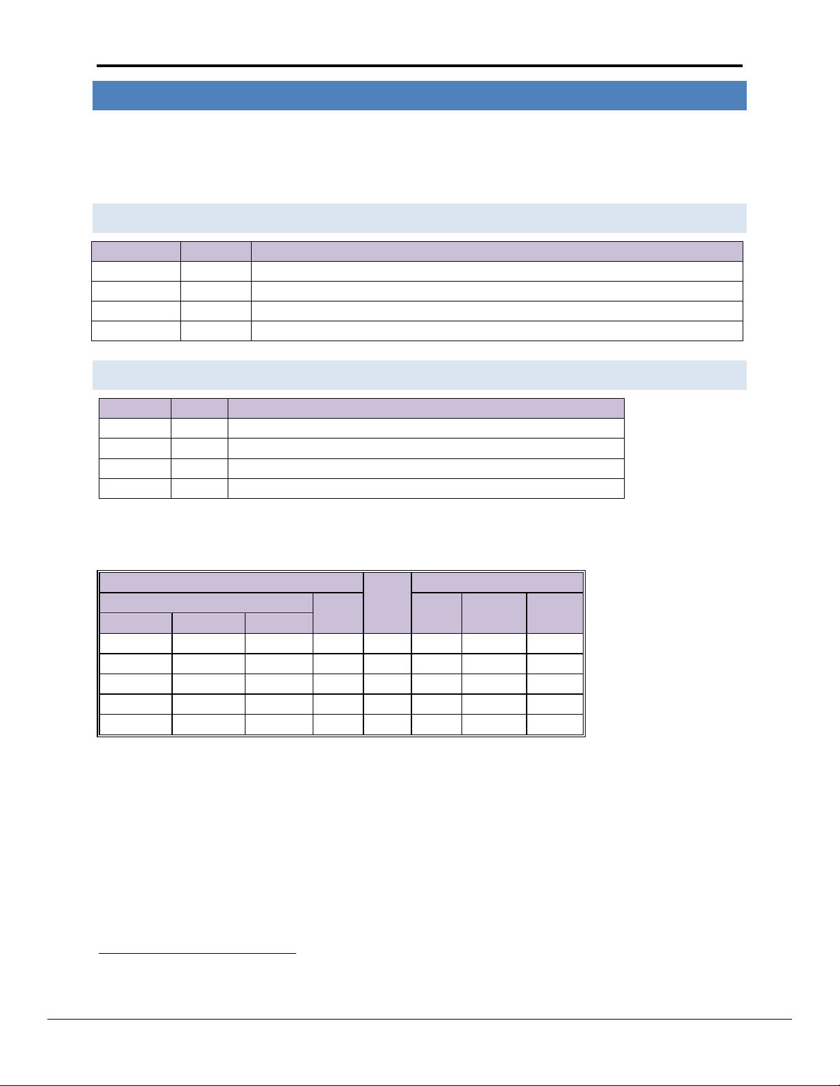
FieldServer Technologies Part #
Description
FS-8917-16
RJ45 to terminal connector cable. (4020 and 4100 Panels)
FS-8917-07
Ethernet cable with 25 pin male connector. (4100u Panels)
SPA59132
RS-485 connection adapter
2 DRIVER SCOPE OF SUPP LY
2.1 Sup plie d by FieldServer Technologies for this driver
2.2 Provided by Supplier of 3
To enable the 4100 Protocol, the 4100 system supplied by the user, must have a free RS-232 port dedicated for use
with the computer device. In most cases, this is not included in the base configuration of the product provided by
Simplex Time Recorder Company, and must be added as a sales option. All 4100 systems limit the number of
computer ports active at one time in a system. To determine the limit for the specific product configuration, refer
to the product specifications, or contact a Simplex sales representative.
rd
Party Equipment
FieldServer Technologies 1991 Tarob Court Milpitas, California 95035 USA Web: www.fieldserver.com
Tel: (408) 262 2299 Fax: (408) 262 2269 Toll Free: (888) 509 1970 email: support@fieldserver.com
Page 6
FS-8700-41 Simplex 4100 Driver Manual Page 6 of 48
Setting
Default
Options
Baud Rate
9600
75, 110, 134.5, 300, 600, 1200, 1800, 2000, 2400, 4800, 9600, 19200
Parity
EVEN1
ODD, EVEN, MARK, SPACE, NONE
Data Bits
8
7 or 8
Stop Bits
1
1 or 2
Setting
Default
Options
Baud Rate
9600
75, 110, 134.5, 300, 600, 1200, 1800, 2000, 2400, 4800, 9600, 19200
Parity
NONE1
ODD, EVEN, MARK, SPACE, NONE
Data Bits
8
7 or 8
Stop Bits
1
1 or 2
4100 Host
Cable
Computer
4100
Signal
Signal
DB25Pin
DB9Pin
Port ATB1
Port BTB2
DB25 Pin
8 1 2
TXD → RXD 2 2 6 3 3 RXD ← TXD 3 3 7 2 4 RTS 2
RTS 4 7
5 4 5
CTS CTS 5 8
4 5 7
GND
──
GND
7
5
1
2
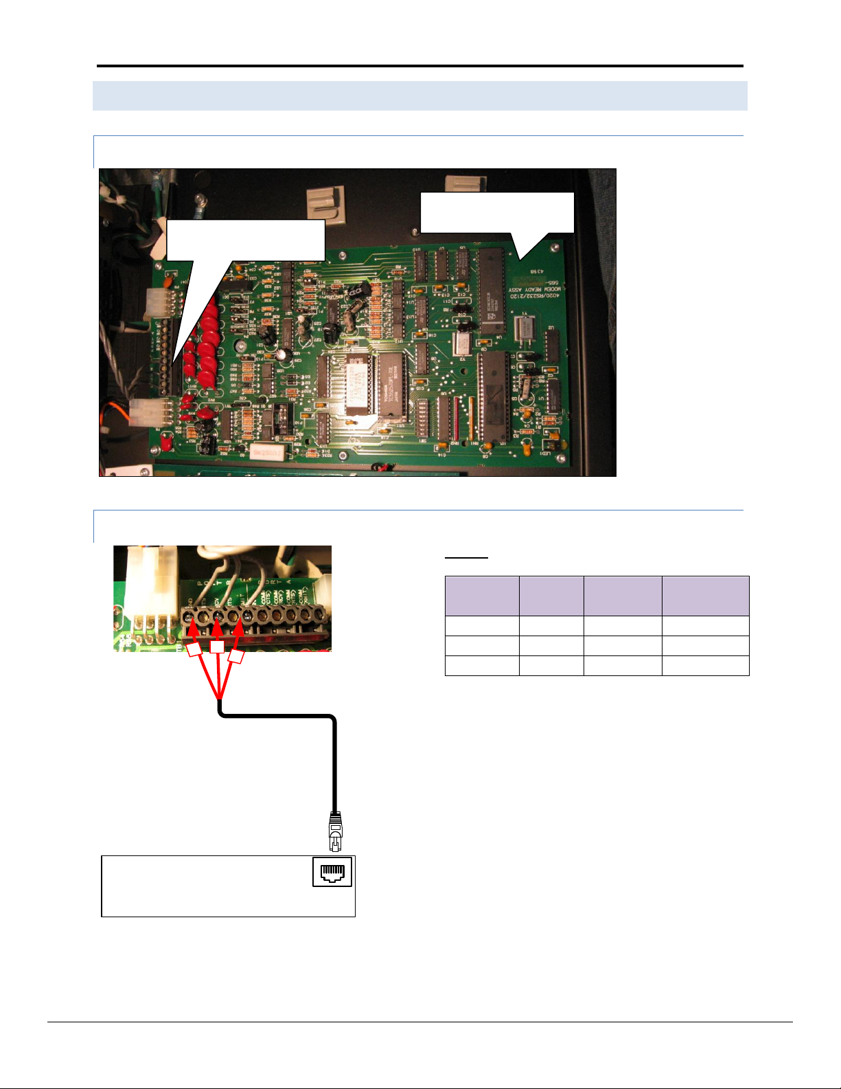
3 HARDWARE CONNECTIONS
The FieldServer is connected to the Simplex Device’s RS-232 port of device type "COMPUTER", the following port
attributes may be configured specifically for that particular port:
Ensure that these settings correspond to the settings described in section 4 of this document.
3.1 Sim 4100 Panel
3.2 Sim 4100U Panel
The following are the Simplex, recommended connections to be used in cabling between the 4100 and the
FieldServer device. For the computer device, the standard EIA signal description, and the 25 pin (DB25) and 9 pin
(DB9) connector assignments are shown.
Odd or Even parity is recommended (by Simplex) to provide additional error detection at the character level.
The driver does not support the Simplex RTS/CTS handshaking model. Therefore deselect the HSHAKE terminal flag or connect CTS to RTS
with a jumper on the 4100 side
FieldServer Technologies 1991 Tarob Court Milpitas, California 95035 USA Web: www.fieldserver.com
Tel: (408) 262 2299 Fax: (408) 262 2269 Toll Free: (888) 509 1970 email: support@fieldserver.com
Page 7
FS-8700-41 Simplex 4100 Driver Manual Page 7 of 48
1
4
8
FS-8917-16
FieldServer
P1
18
FS-X40
Function
From
Simplex
Panel
Terminal
Block #
Rx
RJ45-01
XMIT
6
Tx
RJ45-08
RCV 8 GND
RT45-04
GND
10
Card 4020/RS-232/2120
modem ready assembly.
Terminal Block
Port A =1-5, Port B=6-10.
3.3 Connection to a Simplex 4020/4100 Panel
3.3.1 Communication Board
3.3.2 Seria l C o nnection
Pinouts
FieldServer Technologies 1991 Tarob Court Milpitas, California 95035 USA Web: www.fieldserver.com
Tel: (408) 262 2299 Fax: (408) 262 2269 Toll Free: (888) 509 1970 email: support@fieldserver.com
Page 8
FS-8700-41 Simplex 4100 Driver Manual Page 8 of 48
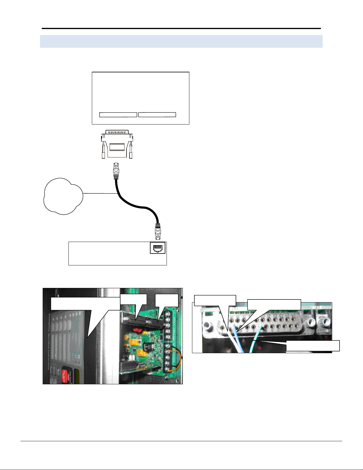
FS-8717-07
Port B
RS-232 Card
Sim4100U Panel
FieldServer
P1
18
8917-07
FieldServer Part #
8915-10
UTP cable
Port B
Port A
Front of 4100U Panel
Pin 2 - White
Pin 3 - Blue
Pin 7 - Green
3.4 Connection to a Simplex 4100U /4100 ES Panel
FieldServer Technologies 1991 Tarob Court Milpitas, California 95035 USA Web: www.fieldserver.com
Tel: (408) 262 2299 Fax: (408) 262 2269 Toll Free: (888) 509 1970 email: support@fieldserver.com
Page 9

FS-8700-41 Simplex 4100 Driver Manual Page 9 of 48
Section Title
Data_Arrays
Column Title
Function
Legal Values
Data_Array_Name
Provide name for Data Array
Up to 15 alphanumeric characters
Data_Array_Format
Provide data format. Each Data Array can only take
on one format.
FLOAT, BIT, UInt16, SInt16,
Packed_Bit, Byte, Packed_Byte,
Swapped_Byte
Data_Array_Length
Number of Data Objects. Must be larger than the
data storage area required by the Map Descriptors
for the data being placed in this array.
1-10, 000
// Data Arrays
Data_Arrays
Data_Array_Name
, Data_Array_Format
, Data_Array_Length
DA_AI_01
, UInt16,
, 200
DA_AO_01
, UInt16
, 200
DA_DI_01
, Bit
, 200
DA_DO_01
, Bit
, 200
4 DATA ARRAY PARAMETER S
Data Arrays are “protocol neutral” data buffers for storage of data to be passed between protocols. It is necessary
to declare the data format of each of the Data Arrays to facilitate correct storage of the relevant data.
Example
FieldServer Technologies 1991 Tarob Court Milpitas, California 95035 USA Web: www.fieldserver.com
Tel: (408) 262 2299 Fax: (408) 262 2269 Toll Free: (888) 509 1970 email: support@fieldserver.com
Page 10

FS-8700-41 Simplex 4100 Driver Manual Page 10 of 48
Section Title
Connections
Column
Title
Function
Legal Values
Port
Specify which port the device is connected to
the FieldServer
P1-P8, R1-R23
Baud*
Specify baud rate
110 – 115200, standard baud rates only.
(Vendor limitation)
Parity*
Specify parity
Even, Odd, None, Mark, Space
Data_Bits*
Specify data bits
7, 8
Stop_Bits*
Specify stop bits
1
Protocol
Specify protocol used
sim4100
Poll Delay*
Time between internal polls
0-32000 seconds, 1 second
// Client Side Connections
Connections
Port
, Protocol
, Baud
, Parity
, Poll_Delay
P8
, Sim4100
, 9600
, Even
, 0.100s
3
5 CONFIGURING THE FIELD S E R V E R A S A S I M PLEX TIME RECORDER C OMPANY - 4100
COMPUT ER PORT PROTOCOL CLIEN T
For a detailed discussion on FieldServer configuration, please refer to the relevant instruction manual. The
information that follows describes how to expand upon the factory defaults provided in the configuration files
included with the FieldServer (See “.csv” files provided with the FieldServer).
This section documents and describes the parameters necessary for configuring the FieldServer to communicate
with a Simplex Time Recorder Company - 4100 Computer Port Protocol Server.
The configuration file tells the FieldServer about its interfaces, and the routing of data required. In order to enable
the FieldServer for Simplex Time Recorder Company - 4100 Computer Port Protocol communications, the driver
independent FieldServer buffers need to be declared in the “Data Arrays” section, the destination device addresses
need to be declared in the “Client Side Nodes” section, and the data required from the servers needs to be
mapped in the “Client Side Map Descriptors” section. Details on how to do this can be found below.
Note that in the tables, * indicates an optional parameter, with the bold legal value being the default.
5.1 Clie n t S ide Connection Parameters
Example
Not all ports shown are necessarily supported by the hardware. Consult the appropriate Instruction manual for details of the ports available
on specific hardware.
FieldServer Technologies 1991 Tarob Court Milpitas, California 95035 USA Web: www.fieldserver.com
Tel: (408) 262 2299 Fax: (408) 262 2269 Toll Free: (888) 509 1970 email: support@fieldserver.com
Page 11

FS-8700-41 Simplex 4100 Driver Manual Page 11 of 48
Section Title
Nodes
Column Title
Function
Legal Values
Node_Name
Provide name for Node
Up to 32 alphanumeric characters
Node_ID
n/a
This parameter is IGNORED. Keywords used to define the
card-sub-point (c-p-s) are described in Appendix A.1
Protocol
Specify protocol used
Sim4100
Port
Specify which port the device is
connected to the FieldServer
P1-P8, R1-R2
PLC_Type*
4020/4100 - panels with firmware
version 9x or earlier.
4100U – panels with firmware
version 10x or later.
4100, 4020, 4100U
Node_Option*
Specify the point status data
format. Refer to Appendix A.1.1
State_Store, Bit_Store
// Client Side Nodes
Nodes
Node_Name
, PLC_Type
, Protocol
, Connection
Device1
, 4100U
, Sim4100
, P1
5.2 Clie n t S ide Node Parameters
Example
FieldServer Technologies 1991 Tarob Court Milpitas, California 95035 USA Web: www.fieldserver.com
Tel: (408) 262 2299 Fax: (408) 262 2269 Toll Free: (888) 509 1970 email: support@fieldserver.com
Page 12

FS-8700-41 Simplex 4100 Driver Manual Page 12 of 48
Column Title
Function
Legal Values
Map_Descriptor_Name
Name of this Map Descriptor
Up to 32 alphanumeric characters
Data_Array_Name
Name of Data Array where data is to be
stored in the FieldServer
One of the Data Array names from Section 4
Data_Array_Offset
Starting location in Data Array
0 to (Data_Array_Length-1) as specified in
“Data_Array” section
Function
Function of Client Map Descriptor
Rdbc, Wrbc, Wrbx
Column Title
Function
Legal Values
Node_Name
Name of Node to fetch data from
One of the Node names specified in
Section 5.2.
Length
Length of Map Descriptor. If data cannot be stored
because an array is too short the driver will produce a
message in the error log.
Any positive integer
Address
Not required. The address is specified by using the c-p-s specification described in section 0
sim4100_func
A keyword which controls the function being
performed or the type of data being polled / written.
Further notes on these keywords are provided in
Appendix C.1
Ackall, Setd, Disable, Restart, Clistall,
Clist, Time, Ctime, Ack, Xpoint, Seta,
Super, Show, Earths, Value, ClearAll
Column Title
Function
Legal Values
sim4100_Card
Simplex Address
<Card>
The following ranges are valid for Simplex Devices:
Card address
Card type
0-119
Physical (Hardware) cards
128-143
Digital Pseudo cards
144-159
Analog Pseudo cards
160-175
List Pseudo cards
sim4100_Point
Simplex Address
<Point>
The range of point and sub-point fields for point addressing is very sparse
and depends on the type of card at that location. Contact Simplex Time
Company for details on point address ranges for specific cards.
The FieldServer will accept any positive integer number including zero;
however, not all the values are valid for Simplex devices – Refer to Appendix
A.1.1 for further information.
sim4100_Sub
Simplex Address
<Sub_Type>
5.3 Clie n t S ide Map Descriptor Parameters
5.3.1 Fie ld Server Specific Map Descriptor Parameters
5.3.2 Driver Specific Map Descriptor Parameters
5.3.3 Card-P oint-Sub Addressing Map Des c r i p t o r Parameters
The Simplex Time Recorder Company - 4100 Computer Port Protocol only uses the standard 4100 address format of
<Card>-<Point>-<Sub-point> (c-p-s). Symbolic addressing is not supported. The following keywords are used to
address devices. Refer to Appendix A.1 for further information and examples
FieldServer Technologies 1991 Tarob Court Milpitas, California 95035 USA Web: www.fieldserver.com
Tel: (408) 262 2299 Fax: (408) 262 2269 Toll Free: (888) 509 1970 email: support@fieldserver.com
Page 13

FS-8700-41 Simplex 4100 Driver Manual Page 13 of 48
Column Title
Function
Legal Values
Scan_Interval
Rate at which data is polled
>0.1s
5.3.4 Timing P arameters
FieldServer Technologies 1991 Tarob Court Milpitas, California 95035 USA Web: www.fieldserver.com
Tel: (408) 262 2299 Fax: (408) 262 2269 Toll Free: (888) 509 1970 email: support@fieldserver.com
Page 14
FS-8700-41 Simplex 4100 Driver Manual Page 14 of 48
Map_Descriptor_Name
, Data_Array_Name
, Data_Array_Offset
, Function
, Node_Name
, sim4100_func
, Scan_Interval
, Length
Time_Mapdesc
, DA_TIME
, 0
, RDBC
, Node_A
, Time
, 30s
, 70
Map_Descriptor_Name
, Data_Array_Name
, Data_Array_Offset
, Function
, Node_Name
, sim4100_func
, Scan_Interval
, Length
Time_Mapdesc
, DA_TIME
, 0
, Wrbc
, Node_A
, CTime
, 30s
, 7
Time_Mapdesc
, DA_TIME
, 0
, Wrbc
, Node_A
, Time
, 30s
, 7
Map_Descriptor_Name
, Data_Array_Name
, Data_Array_Offset
, Function
, Node_Name
, sim4100_func
, Scan_Interval
, Length
Error_Mapdesc
, DA_REV_INFO
, 0
, Rdbc
, Node_A
, Revision
, 30s
, 200
Index 0: Hour (24 hour clock)
Index 1: Minute
Index 2: Second
Index 3: Day of week
Index 4: Day of month
Index 5: Month
Index 6: Year (since 2000)
Rdb may be sufficient as this data
does not change.
5.3.5 Map Descriptor Example 1. - R e a d P a n e l T i m e
5.3.6 Map Descriptor Example 2 - W r i t e P ane l Time
Use Ctime to set the panel time and date and use Time just to set the hour minute and seconds. If the hour is zero then the driver does not send a write
message to the panel.
5.3.7 Map Descriptor Example 3 - P ane l R e v ision Inf ormation
Define the DA_REV_INFO array as format BYTE and if using RUINET to monitor this Data Array change the display format to string to render the information
readable.
FieldServer Technologies 1991 Tarob Court Milpitas, California 95035 USA Web: www.fieldserver.com
Tel: (408) 262 2299 Fax: (408) 262 2269 Toll Free: (888) 509 1970 email: support@fieldserver.com
Page 15

FS-8700-41 Simplex 4100 Driver Manual Page 15 of 48
6 CONFIGURING THE FI E L DSERVE R AS A SI MPLEX TIME RECORDER C O MPA N Y - 4100 COMPUTER
PORT PROTOCOL SERVER
The driver contains some Server side functionality which has been developed to meet FieldServer’s continuous quality
assurance efforts. However, the Server side functions are not documented or supported for customer use. If you have a
strong requirement for this functionality then please contact the Sales and Marketing group of FieldServer.
FieldServer Technologies 1991 Tarob Court Milpitas, California 95035 USA Web: www.fieldserver.com
Tel: (408) 262 2299 Fax: (408) 262 2269 Toll Free: (888) 509 1970 email: support@fieldserver.com
Page 16

FS-8700-41 Simplex 4100 Driver Manual Page 16 of 48
# Subpoints/point Calculated Offset
Sim4100_sub
0 1 2 3 4 5 6 ...
1 s per p
implies s=0 every time
c-0-0
c-1-0
c-2-0
c-3-0
c-4-0
c-5-0
c-6-0
...
2 s per p
implies s=0,1 for each p
c-0-0
c-0-1
c-1-0
c-1-1
c-2-0
c-2-1
c-3-0
...
5 s per p
implies s=0,1,2,3,4 for each p
c-0-0
c-0-1
c-0-2
c-0-3
c-0-4
c-0-5
c-1-0
...
x s per p
implies s=0,1,…(x-1)
c-0-0
c-0-1
c-0-2
c-0-3
c-0-4
c-0-5
c-0-6
...
...
, sim4100_func
, sim4100_card
, sim4100_point
, sim4100_sub
, data_array_offset
, Length
, Xpoint
, 10
,20
, 10
, 0
, 100
The length parameter reserves space in Data Array Items in
the Map Descriptor. If the calculated length exceeds the
length an error is printed and no data is stored (for Xpoint).
Appendix A. Useful Features
Appendix A.1. How to use Data Arrays to map to/from Card-Point-Sub addresses
Some commands derive a c-p-s address by inspecting a FieldServer Data Array. Others receive data from a device and modify
the data in an array based on the c-p-s address. This section explains how to make the connection between an index into a
Data Array and a c-p-s address.
To minimise the required Data Array size the FieldServer uses a mapping algorithm which can be optimized based on the
addresses of the Simplex devices. The map is manipulated by using the sim4100_card/point/sub parameter values.
If there are one sub-point (s) per point (p) then only one array location is required for each p.
If there are two sub-point (s) per point (p) then two array locations are required for each p.
If there are x sub-point (s) per point (p) then x array locations are required for each p.
This is more clearly explained in the table below:
Thus the offset into the Data Array is determined according to the following formula.
Data Array Offset = Offset specified on the Map Descriptor (Data_Array_Offset ) + Calculated Offset
Example:
Consider the following Map Descriptor fragment.
If data is received for point <c>-<p>-<s> = 9-0-0, this data will NOT be processed because the card number does not match
the value of the sim4100-card
If data is received for point <c>-<p>-<s> = 10-20-0, however, the data will be processed.
The array location is derived using the following formula (sim4100_sub is to be read as the “number of sub-points per point”;
sim4100_card’s value will be ignored.)
Location = data_array_offset + <p> * sim4100_sub + <s>
= 0 + 20 * 10 + 0 = 200
FieldServer Technologies 1991 Tarob Court Milpitas, California 95035 USA Web: www.fieldserver.com
Tel: (408) 262 2299 Fax: (408) 262 2269 Toll Free: (888) 509 1970 email: support@fieldserver.com
Page 17

FS-8700-41 Simplex 4100 Driver Manual Page 17 of 48
Bit
Identifier
State Store
Value
Bit Store
Value
Description
0 (First
Bit)
F 1 0
Fire Alarm
1 P 2 1 Priority 2
2 S 3 2 Supervisory
3 T 4 4 Trouble
4 U 5 8 Utility
5 C 6
16
Control
6 D 7
32
Disable
7 A 8
64
Primary state (based on point type - F if smoke detector, C if
signal circuit, etc.)
Appendix A.1.1. Simplex Point S t a t us Data For m a t
When a point status is obtained the FieldServer will, by default, write one byte of data to a Data Array. The byte will contain
the following information. Ensure that the funcion of the Data Array Type used is not Bit..
State or Bit Store options can be chosen using the Node_Option Parameter. The value provided depending on the option
chosen is shown in the appropriate column in the Data Array.
Appendix A.2. SHOW Function Attributes and Attribute States
The Show command provides an ASCII response formatted for printing. The driver parses these messages and converts the
data to numbers which can be sent to Client devices using another protocol.
The driver performs the following tasks in analyzing the response.
On a line by line basis from the left, it searches for an attribute against a table of attribute strings. If an attribute string is
found, processing continues. Otherwise the line is discarded.
The attribute number is used to determine the array location where the attribute state/value will be stored.
The attribute also determines the state/value extraction method.
Method 1: The driver compares the remainder of the line against a table of attribute states. The value of the
attribute state is stored in the array location determined by the attribute,
Method 2: The driver looks for (up to three) analog values separated by forward slashes.
Method 3: The driver looks for analog values preceded by an equal sign.
The driver stores in the first array location the number of response lines which resulted in attribute data being stored.
This information can be used for troubleshooting.
FieldServer Technologies 1991 Tarob Court Milpitas, California 95035 USA Web: www.fieldserver.com
Tel: (408) 262 2299 Fax: (408) 262 2269 Toll Free: (888) 509 1970 email: support@fieldserver.com
Page 18

FS-8700-41 Simplex 4100 Driver Manual Page 18 of 48
Attribute
Array
Position
Method
Not Defined
0 1 PRIMARY STATUS
1 1 PHYSICAL STATE
2
1
RAW STATE
3
1
ACTIVE STATE
4 1 ARMED STATE
5 1 ENABLED STATE
6 1 UNVERIFIED
7
2
CURRENT DEVICE
8
1
DEVICE
9 1 TEST STATE
10 1 PRESENT SENSITIVITY SELECTED=
11
2
PRESENT SENSITIVITY SELECTED =
11 2 AVERAGE VALUE =
14
3
AVERAGE VALUE=
14 3 AVERAGE =
14 2 AVERAGE=
14
2
AVERAGE
14
2
VALUE =
17 2 VALUE=
17 2 PEAK=
20 2 PEAK =
20
2
TROUBLE THRESHOLD
23
1
OUTPUT STATE
24 1 OUTPUT STATUS
25 1 DETECTOR SOUNDER
26
1
Attribute
Array
Position
Method
ALARM TEMPERATURE SELECTED=
27 2 DETECTOR RELAY
30 1 TOTAL NUMBER OF TROUBLES
31
2
NODE MISSING
32
1
VERSION CONTROL
33 1 NODE INITIALIZATION IN PROGRESS
34 1 SIMPLEX SERVICE MODE
35 1 EARTH GROUND
36
1
AC POWER
37
1
BATTERY LOW/DISCHARGED
38 1 BATTERY CHARGE
39 1 SYSTEM PSEUDO STATUS
40
1
NETWORK CARD STATUS
41 1 CARD TROUBLE STATUS
42
1
MISCELLANEOUS STATUS
43 1 RELAY STATUS
44 1 PRIORITY
45
2
CONTROL STATUS
46
1
CURRENT (AMPS)
47 2 CARD MISSING/FAILED
48 1 CORRECT CARD
49 1 RS-232 Interface PORT A
40
1
RS-232 Interface PORT B
41
1
2120/RS-232 PORT Broadcast Fail
42 1 CARD MISSING/FAILED
43
1
Appendix A.2.1. Ta ble of Attr i b u t es recogn is e d b y t h e Driver
The following table reports the attributes recognized by the driver. This list may be extended by changing the configuration.
Refer to Appendix A.3 for more information. If, for example, the attribute ‘ENABLED STATE’ is recognized then the state of
this attribute will be stored at array location 6.
FieldServer Technologies 1991 Tarob Court Milpitas, California 95035 USA Web: www.fieldserver.com
Tel: (408) 262 2299 Fax: (408) 262 2269 Toll Free: (888) 509 1970 email: support@fieldserver.com
Page 19

FS-8700-41 Simplex 4100 Driver Manual Page 19 of 48
Attribute State
Value
AUTOMATIC CONTROL
1
OUTPUT NORMAL
2
SELF TEST NORMAL
3
CORRECT DEVICE
4
PRIORITY 15
5
RANGE NORMAL
6
ALARM
7
SHORT
8
SHORT
9
ARMED
10
ENABLED
11
ON-LINE
12
ENABLED
13
NORMAL
14
TROUBLE
15
OFF
16
ON
17
0
Appendix A.2.2. Attribute Sta t e s recognised f o r A t tribute M et h o d 1
The table below reports the attribute states recognized for attribute method=1.
Examples:
PHYSICAL STATE SHORT
The Driver recognizes ‘Physical State’ as attribute 2 and uses method 1 to evaluate the rest of the line. The attribute state
SHORT has a value of 8. The number 8 is stored at location 2 in the Data Array.
VALUE=77 / 0% OF ALARM / 1.0% SMOKE
The Driver recognizes ‘VALUE=’ as attribute 17 and uses method 2 to evaluate the rest of the line. The Driver stores the
values; 77, 0 and 1.0 in three consecutive locations starting at location 17. Note that there is a gap between attribute 17 and
the next attribute in the table sufficient for storing up to 3 values. The three values are seperated by slashes.
AVERAGE VALUE=75 / ALARM LEVEL=145
The Driver recognizes ‘AVERAGE VALUE’ as attribute 14 and uses method 3 to evaluate the rest of the line. The Driver stores
the values; 75 and 145 in two consecutive locations starting at location 14. An equal sign ‘=’ precedes each numeric value.
FieldServer Technologies 1991 Tarob Court Milpitas, California 95035 USA Web: www.fieldserver.com
Tel: (408) 262 2299 Fax: (408) 262 2269 Toll Free: (888) 509 1970 email: support@fieldserver.com
Page 20

FS-8700-41 Simplex 4100 Driver Manual Page 20 of 48
Column Title
Function
Legal Values
Protocol
Specify protocol used
Sim4100
sim4100_Attr_Name
The SHOW command response consists of a number of
attributes and their current state/values. This parameter
is used to add a new attribute to the table.
The exact character
sequence must be
specified. May include an
= sign.
sim4100_Attr_Offset
This parameter defines the offset in the Data Array where
the current state/value of the attribute with the name
defined above must be stored. Ensure there is sufficient
space for attributes with multiple values.
May not be zero.
sim4100_Attr_Method
This parameter selects the method for converting the
current state/value for storage in the Data Array.
1,2,3
May not be zero.
Column Title
Function
Legal Values
Protocol
Specify protocol used
Sim4100
sim4100_Attr_State_Name
Use this parameter to extend this list of
predefined attribute states.
Define a state word such as ‘Normal’ and associate
a value using the ‘value’ parameter.
sim4100_Attr_State_Value
This parameter is the value to be
associated with the ‘name’
May not be zero.
Driver_Table
sim4100_Attr_Name
, sim4100_Attr_Offset
, sim4100_Attr_Method
, Protocol
BROKEN
, 30
, 1
, sim4100
FIXED
, 31
, 1
, sim4100
LIGHT STATE
, 32
, 1
, sim4100
Driver_Table
sim4100_Attr_State_Name
, sim4100_Attr_State_value
, Protocol
DIM
, 40
, sim4100
BRIGHT
, 41
, sim4100
Attribute States.
Use values that are not allocated to the predefined list of states.
Protocol must
be defined on
every line.
Protocol must
be defined on
every line.
Keyword starts a
new section of the
CSV file.
Attribute Definitions. The
name will be stripped of
all spaces between the
last character and the
comma.
Ensure that unique
offsets are
allocated.
Use a digit. The three
methods are
described above.
Appendix A.3. Extending the List of Show Attributes
The list of attributes and attribute states that the driver recognizes can be extended by modifying the configuration CSV file.
Appendix A.3.1. ShowRespon s e A t t ributes Dri v e r T a b le
Appendix A.3.2. Show Respon s e A t t ribute S tates Driv er T a b le
The following example adds three attributes and 4 attribute states. If a device reports an attribute of ‘LIGHT STATE’ as
‘BRIGHT’ then the driver will load array element 32 with the value 41.
FieldServer Technologies 1991 Tarob Court Milpitas, California 95035 USA Web: www.fieldserver.com
Tel: (408) 262 2299 Fax: (408) 262 2269 Toll Free: (888) 509 1970 email: support@fieldserver.com
Page 21

FS-8700-41 Simplex 4100 Driver Manual Page 21 of 48
Map_Descriptor_Name
, Data_Array_Name
, Data_Array_Offset
, Function
, Node_Name
, sim4100_func
, sim4100_card
, sim4100_point
, sim4100_Sub
, Length
Clear_Mapdesc1
, DA_AI
, 0
, Passive
, Node_A
, ClearAll
, 1
, 2
, 3
, 100
Clear_Mapdesc1
, DA_2
, 50
, Passive
, Node_A
, ClearAll
, 1
, 2
, 3
, 50
Map_Descriptor_Name
, Data_Array_Name
, Data_Array_Offset
, Function
, Node_Name
, Length
, Scan_Interval
, sim4100_func
, sim4100_card
, sim4100_point
, sim4100_sub
A1
, DA_AI3
, 0
, Rdbc
, Node_A
, 1
, 5
, Clist
, 1
, 2
, 3
Two different arrays, starting at two
different locations and with two
different lengths will get set to zero
when c-p-s=1-2-3 goes to state U1.
The sim400_func must be
ClearAll.
An Xpoint Map Descriptor must be
created for any clear all c-p-s. The clear
all logic never gets called until an Xpoint
store is done for the c-p-s configured to
do ClearAll.
The Data extracted
from the device is
placed in this driver
independent data
array.
This identifier must be
the same as the Node
Name used to identify
the port connected to
the Simplex device
being described in this
Map Descriptor.
Ignored for the Simplex
protocol unless the
sim4100_func=ackall,
clearall,
Simplex Device: Card
Perform the 'Computer List
Status' Function to (in this
case) read the current point
status of the point specified
by card-point-sub. This
function returns fire,
supervisory, trouble.... data.
The format of the returned
data is described in Appendix
A.1
The data is written
into the array
starting at this
position. A value of
zero is equivalent to
the first position.
Simplex Device: Point
Simplex Device: Sub-Point
Appendix A.4. Map Descriptor Examples
Appendix A.4.1. ClearAll
Since an Xpoint message only reports when a c-p-s goes into a non-normal state, this function is provided as a means of synchronising FieldServer to the panel
when everything is normal. The function is typically used in conjunction with pseudo-point(s) programmed into the panel. The underlying logic assumes that
the affected point(s) trigger the driver to clear sections of one or more Data Arrays when they report a state of U1
If an Xpoint message is received from the Panel for the specified c-p-s with the ClearAll function (or clist is used to poll for the state of the c-p-s) and the state
is U1, this triggers this ClearAll action. The driver sets all array points covered by all Map Descriptor’s with the clearal l function to zero, without consideration
of the c-p-s associated with the Map Descriptor.
Appendix A.4.2. Rea d Point St a t u s
This Map Descriptor can be used to poll for the status of a particular point. When the response is obtained the driver sets the value of one Data Array element
to a number indicating the point’s status. The values are described in . One Map Descriptor is required for every point polled.
FieldServer Technologies 1991 Tarob Court Milpitas, California 95035 USA Web: www.fieldserver.com
Tel: (408) 262 2299 Fax: (408) 262 2269 Toll Free: (888) 509 1970 email: support@fieldserver.com
Page 22

FS-8700-41 Simplex 4100 Driver Manual Page 22 of 48
Map_Descriptor_Name
, Data_Array_Name
, Data_Array_Offset
, Function
, Node_Name
, sim4100_func
, sim4100_card
, sim4100_point
, sim4100_sub
, Length
A1
, DA_AI3
, 0
, Passive
, Node_A
, xpoint
, 1
, 0
, 10
, 1000
The Data extracted
from the device is
stored in this driver
independent data
array.
Must be passive
Driver stores
data from
unsolicited
Xpoint
messages
Simplex Device: Card
All point-subpoint data
for this card are stored
using this Map
Descriptor.
Set this to zero for Xpoint
Map Descriptor.
When used with an Xpoint Map Descriptor this parameter
allocates the number of sub-points per point. In this case the
driver uses 10 array locations for each point.
Thus
Point 0: Array locations 0-9
Point 1: Array location 10-19
Point 2: Array locations 20-29 …
E.g. If the Xpoint message is for 1-1-0 then the state will be
stored at location 10.
If the Xpoint message is for 1-2-5 then the state will be
stored at location 25.
Appendix A.4.3. Using unsoli c i t e d messages f r o m t h e Panel to d e t e rmine point st a t u s
This Map Descriptor can be used to store point status data when the FieldServer receives an unsolicited message from the Panel containing point status
information (Xpoint messages). The panel sends an Xpoint message each time a point’s status changes to a non-normal state. Using these Map Descriptors
will ensure that the FieldServer is constantly updated with the latest panel status information. The Map Descriptor’s are pa ssive so they can be used in a joint
strategy with the clist function (Appendix A.3.1) to keep track of a point’s status.
One Xpoint Map Descriptor is required for storage of Xpoint messages from each card. For a given card, the driver uses a mapping function based on the pointsubpoint address to determine the array location to store the state for the c-p-s.
FieldServer Technologies 1991 Tarob Court Milpitas, California 95035 USA Web: www.fieldserver.com
Tel: (408) 262 2299 Fax: (408) 262 2269 Toll Free: (888) 509 1970 email: support@fieldserver.com
Page 23

FS-8700-41 Simplex 4100 Driver Manual Page 23 of 48
Map_Descriptor_Name
, Data_Array_Name
, Data_Array_Offset
, Function
, Node_Name
, sim4100_func
, Scan_Interval
, Length
AckAll_Mapdesc
, DA_ACKALL
, 0
, Wrbx
, Node_A
, AckAll
, 1.0s
, 6
2nd – ack
A
Primary Abnormal State
3rd – ack
F
Fire alarm
4th – ack
P
Priority 2
5th – ack
S
Supervisory
6th – ack
T
Trouble
Map_Descriptor_Name
, Data_Array_Name
, Data_Array_Offset
, Function
, Node_Name
, Length
, Scan_Interval
, sim4100_Func
, Sim4100_Card
, Sim4100_Point
, Sim4100_Sub
Ack_mapdesc1
, DA_ACK
, 0
, Wrbx
, Node_A
, 1
, 1.0s
, Ack
, 1
, 2
, 3
Ack_Mapdesc2
, DA_ACK
, 1
, Wrbx
, Node_A
, 1
, 1.0s
, Ack
, 1
, 2
, 4
Bit 0:
F
- Fire Alarm Panel
Bit 1:
P
- Priority 2 alarm state
Bit 2:
T
- Trouble State
Bit 3:
S
- Supervisory State
Bit 4:
U
- Utility Monitor
Bit 5:
C
- Control State
Bit 6:
D
- Disable Trouble State
Bit 7:
A
- Primary Point
The function is Wrbx, the message is only sent when
the value is updated.
Appendix A.4.4. Acknowledge A l l P o ints
The ackall function can be used to ack all points or all points that are in a particular state. Each time the driver uses th is Map Descriptor, it checks the data in the Data
Array. If a location is non-zero then the appropriate Ack message is sent to the panel.
The 1st element of the Data Array is used to trigger the ack all
Set the array element to 1 to initiate the command. The FieldServer clears the value on completion
Appendix A.4.5. Acknowledge a s p e cific point
One Map Descriptor is required for each c-p-s combination requiring specific acknowledgements. The driver checks the array location corresponding to the Map
Descriptor. If the value is non-zero then an ack message is sent. The value is used to determine what kind of ack is sent.
FieldServer Technologies 1991 Tarob Court Milpitas, California 95035 USA Web: www.fieldserver.com
Tel: (408) 262 2299 Fax: (408) 262 2269 Toll Free: (888) 509 1970 email: support@fieldserver.com
Page 24

FS-8700-41 Simplex 4100 Driver Manual Page 24 of 48
Map_Descriptor_Name
, Data_Array_Name
, Data_Array_Offset
, Function
, Node_Name
, sim4100_func
, Scan_Interval
, Length
Silence_Mapdesc
, DA_TRIGGERS
, 0
, Wrbx
, Node_A
, Silence
, 1.0s
, 6
Reset_Mapdesc
,DA_TRIGGERS
, 1
, Wrbx
, Node_A
, Reset
, 1.0s
, 6
Map_Descriptor_Name
, Data_Array_Name
, Data_Array_Offset
, Function
, Node_Name
, sim4100_func
, sim4100_card
, sim4100_point
, sim4100_Sub
, Length
Clear_Mapdesc1
, DA_I
, 0
, passive
, Node_A
, Ack
, 1
, 2
, 3
, 100
Clear_Mapdesc1
, DA_2
, 0
, passive
, Node_A
, Ack
, 1
, 2
, 3
, 100
Map_Descriptor_Name
, Data_Array_Name
, Data_Array_Offset
, Function
, Node_Name
, Length
, Scan_Interval
, sim4100_Func
, Sim4100_Card
Earth_mapdesc1
, DA_EARTHS
, 0
, Rdbc
, Node_A
, 20
, 1.0s
, Earths
, 1
If location 0 goes non-zero then a silence message is sent. If location
1 goes non-zero then a reset message is set.
Driver’s set the trigger back to zero once the message has been set.
Two different arrays, starting at two
different locations and with two
different lengths will get set to zero
when c-p-s=1-2-3 goes to state U1.
If 1-2-3 or 1-2-4 go to state U1 then the
Data Array regions associated with both
Map Descriptors are set to zero.
The function is Wrbx, the message is only sent when
the value is updated.
Appendix A.4.6. Silence / Re s e t
Note: When configured as a Server, the driver increments the value in the associated DA element each time a silence/reset is received.
Appendix A.4.7. Earths
This function is only available for panel firmware versions 10.0 and later. This function reads earth / ground status information from the panel.
If, for example, card 3 reports information then the driver uses array elements 6 & 7 to store information for this card. Obtain the array location by multiplying the
card number by two.
If the card reports positive and negative earth data then the driver stores the positive earth data at location 6 and the negative earth data at location 7.
If the card reports earth / ground state information without the keywords ‘Positive’ or ‘Negative’ the driver stores the data at location 6.
The driver stores a value of 1 to report normal and a value of 2 to report abnormal.
FieldServer Technologies 1991 Tarob Court Milpitas, California 95035 USA Web: www.fieldserver.com
Tel: (408) 262 2299 Fax: (408) 262 2269 Toll Free: (888) 509 1970 email: support@fieldserver.com
Page 25

FS-8700-41 Simplex 4100 Driver Manual Page 25 of 48
Map_Descriptor_Name
, Data_Array_Name
, Data_Array_Offset
, Function
, Node_Name
, Length
, Scan_Interval
, sim4100_Func
, Sim4100_Card
, Sim4100_Point
, Sim4100_Sub
Show_mapdesc1
, DA_SHOW
, 0
, Rdbc
, Node_A
, 100
, 1.0s
, Show
, 1
, 2
, 3
Appendix A.4.8. Show
One Map Descriptor is required for each point whose attributes you wish to ‘show’. The show function reads data that describe s the attributes and the state of each
attribute for a single device. Every type of device has a different set of attributes. When the response is received by the driver, it fills a number of Data Array locations
with numeric values that represent the attributes and their states. You should reserve at least 100 array locations for each Map Descriptor by setting the length to 100.
By way of example assume that point 1-2-3 is a Heat Detector and the response to the show query is as follows
40 Character Custom Label
Mx-y-2 HEAT DETECTOR
DEVICE ADDRESS: 7-10-2 TYPE: COMBO
IDNET INTERFACE CARD
LOCAL UNIT – MAIN PANEL
UNIT NUMBER: 0 RUI NUMBER: LOCAL
---------------------------------------PRIMARY STATUS NORMAL
CURRENT DEVICE CORRECT DEVICE
DEVICE ON_LINE
TEST STATE SELF TEST NORMAL
ALARM TEMPERATURE SELECTED= 135 DEG F
VALUE=0 / -41 DEG F
PEAK=0 / -41 DEG F
TROUBLE THRESHOLD RANGE NORMAL
ENABLED STATE ENABLED
UNVERIFIED 0
The driver will load the array DA_SHOW starting at offset zero for up to 100 elements. The following table can be used to determine the values to expect for this
response.
FieldServer Technologies 1991 Tarob Court Milpitas, California 95035 USA Web: www.fieldserver.com
Tel: (408) 262 2299 Fax: (408) 262 2269 Toll Free: (888) 509 1970 email: support@fieldserver.com
Page 26

FS-8700-41 Simplex 4100 Driver Manual Page 26 of 48
Array
Posn
Attribute
Value
Filled
In4
Note
0
Not Defined
10
1
The value 10 represents the count of the number of attributes that were extracted from the response. It is not equal to the number of array
locations filled in because some attributes (e.g. Value) result in more than one array location being updated.
1
PRIMARY STATUS
14 (Normal)
1
#
2
PHYSICAL STATE
The un-filled-in locations are not updated by the driver when this response is analysed because the attributes corresponding to these
locations were not reported in the response to the query.
3
RAW STATE
4
ACTIVE STATE
5
ARMED STATE
6 ENABLED STATE
11 (Enabled)
1 7
UNVERIFIED
0 1
8
CURRENT DEVICE
4 (Correct
Device)
1
9
DEVICE
12 (On_Line)
1
10
TEST STATE
3 (Self test
normal)
1 11
PRESENT SENSITIVITY
SELECTED
14
AVERAGE
17
VALUE
0 1
18 -41 1
19 Room for up two three numbers for attributes like value, peak but in this case only two values are relevant for this device
20
PEAK 0 1
21 -41 1
22 Room for up two three numbers for attributes like value, peak but in this case only two values are relevant for this device
23
TROUBLE THRESHOLD
6 (Range
Normal)
1
24
OUTPUT STATE
25
OUTPUT STATUS
26
DETECTOR SOUNDER
27
ALARM TEMPERATURE
SELECTED=
135 1
30
DETECTOR RELAY
4
Locations marked with a 1 are updated when the driver analyses this response
FieldServer Technologies 1991 Tarob Court Milpitas, California 95035 USA Web: www.fieldserver.com
Tel: (408) 262 2299 Fax: (408) 262 2269 Toll Free: (888) 509 1970 email: support@fieldserver.com
Page 27

FS-8700-41 Simplex 4100 Driver Manual Page 27 of 48
// Analog Psuedo points
// Map Descriptor
Map_Descriptor_Name
, Data_Array_Name
, Data_Array_Offset
, Function
, Node_Name
, Sim4100_Func
, Sim4100_Card
, Sim4100_Point
, Sim4100_Sub
, Protocol
, Length
# Fire Alarms
, DA_C_144
, 0
, Rdbc
, Simplex_01
, value
, 144
, 0
, 0
, sim4100
, 1
# Supervisory Alarms
, DA_C_144
, 1
, Rdbc
, Simplex_01
, value
, 144
, 1
, 0
, sim4100
, 1
# Troubles
, DA_C_144
, 2
, Rdbc
, Simplex_01
, value
, 144
, 2
, 0
, sim4100
, 1
Excessively Dirty Sensors
, DA_C_144
, 3
, Rdbc
, Simplex_01
, value
, 144
, 115
, 0
, sim4100
, 1
Dirty Sensors
, DA_C_144
, 4
, Rdbc
, Simplex_01
, value
, 144
, 116
, 0
, sim4100
, 1
Almost Dirty Sensors
, DA_C_144
, 5
, Rdbc
, Simplex_01
, value
, 144
, 117
, 0
, sim4100
, 1
Appendix A.4.9. Rea d Analog P s u e d o Poin t s
Use the Sim4100_func = 'value' to read the values from the analog pseudo points. Refer to Appendix C.4.2 for a list of the analog pseudo points.
FieldServer Technologies 1991 Tarob Court Milpitas, California 95035 USA Web: www.fieldserver.com
Tel: (408) 262 2299 Fax: (408) 262 2269 Toll Free: (888) 509 1970 email: support@fieldserver.com
Page 28

FS-8700-41 Simplex 4100 Driver Manual Page 28 of 48
Network Card #
5
Network Point #
Card #
Slot #
Point #
C-P-S Address
1 5 1 0 5-1-0
2 5 1 1 5-1-1
3 5 1 2 5-1-2
4 5 1 3 5-1-3
5 5 1 4 5-1-4
..
..
Appendix A.5. Networked Panels
If two or more Simplex panels are networked together, the FieldServer can poll the information from both. The
Simplex panels will need network cards installed and programmed by Simplex to pass the points to the panel
connected to the FieldServer. The points from the networked panel(s) will be in the same Card -Point-Subpoint
format (c-p-s) as the main panel. An algorithm is used to ensure that Point Sub point numbers stay the same and
only the network card number changes. A network card with point address of 61, sub point 98, card address 5 will
show up on the panel as as 5-61-98. Network points are numbered as follows: C-1-0 is network point 1, C-1-1 is
point 2, C-1-2 is point 3 and so on up to C-1-255 which is point 256. The sequence then starts again (C-2-0 through
C-2-255 points 257 to 512). Refer also to Appendix B.3.
The equation to calculate the network point # based off of the C-P-S is as follows:
Network Point # = ((<P> - 1) * 256) + <S> + 1
Example:
Appendix A.6. Synchronizing the FieldServer with the Panel
Appendix A.6.1. Using the Xpo i n t Function
When using the Xpoint function to store point states, each time the panel does a warm-start it sets all point states
to normal and then starts evaluating each one. Thus, the FieldServer will receive Xpoint messages from the panel
for every point not in a normal state. The limitation of this method is that the Simplex panels do not report when a
point’s state changes back to normal. Thus to maintain the synchronization the Client device must clear the point
to zero once it has read its abnormal state, i.e. The Client device should consider the data reported by the Xpoint
function as latched data.
This way the FieldServer states will always be updated. Polling is slow and in a system with many points it may
take several minutes to update status information for all points. Thus combining this method with the use of
Xpoint Map Descriptors gives the best of both worlds. When a point changes to ‘not’ normal, then the FieldServer
gets the state change from the Xpoint function immediately and at the same time synchronization is assured by
the continuous polling.
FieldServer Technologies 1991 Tarob Court Milpitas, California 95035 USA Web: www.fieldserver.com
Tel: (408) 262 2299 Fax: (408) 262 2269 Toll Free: (888) 509 1970 email: support@fieldserver.com
Page 29

FS-8700-41 Simplex 4100 Driver Manual Page 29 of 48
Column Title
Function
Legal
Values
sim4100_WriteThru*
Only appropriate when the sim4100_func=clist.
Controls the write through behavior of the clist function.
Onoff,
value
Store_Unsolicited*
Control the ability of ‘CLIST’ map descriptors to be used to store data from unsolicited messages. Refer also to
Appendix A.6.2
Yes, No
Appendix A.6.2. Using Clist to W r ite-Thr o u gh and Stor e p o i n t status from Unsol i ci t e d M essages
This function is only available for panel version 1.05 and above.
The ‘Clist’ Map Descriptors can
Read a point’s status
Write to a point when a Write-Through is activated
Store the point status when an ‘Xpoint’ unsolicited message is received from the panel.
A Write-Through occurs when a Data Array value that is normally updated by a read (Rdbc) Map Descriptor is updated by some other driver or by using the
Ruinet application. The updated value is written through the Rdbc Map Descriptor to the panel. The value is written once only each time that the Data Array
element is updated except when the value is updated by the response to the read or if the point status is updated when an uns olicited message is received
from the panel.
Ensure that the point is not a read only point and the Panel’s access level has been set appropriately.
When an unsolicited message is received from the panel it would normally be stored using a Map Descriptor with the ‘Xpoint’ function. (See section Appendix
A.4.3) However, if polling for the status of that point using a ‘Clist’ Map Descriptor with ‘Store_Unsolicited’ set to yes then omit the ‘Xpoint’ Map Descriptor as
the ‘Clist’ Map Descriptor can be used to store the point status when it is updated with an unsolicited message. If both Map Descriptor’s are defined then the
result will be unpredictable.
A write command can be sent to a Simplex panel in one of two formats:
SET c-p-s ON/OFF (default)
SET c-p-s value
Use the sim4100_WriteThru parameter in the CSV to change to the 2nd format.
Even if writing to an analog pseudo point, format 1 is suitable because enabling the point forces it to take its intrinsic value. On setting the point off it’s value is
set to zero.
FieldServer Technologies 1991 Tarob Court Milpitas, California 95035 USA Web: www.fieldserver.com
Tel: (408) 262 2299 Fax: (408) 262 2269 Toll Free: (888) 509 1970 email: support@fieldserver.com
Page 30

FS-8700-41 Simplex 4100 Driver Manual Page 30 of 48
Appendix B. Troubleshooting
Appendix B.1. Address Errors
If the driver produces BAD_ADDRESS stats then do the following
Refer to Appendix A.4.1. and create a Map Descriptor which will save the most recent error in the Data Array
DA_ERRORS.
Alternatively, take a log, open the ASCII version of the log and look for error messages. Error 2 is the response
sent by the panel when it is polled for a point that doesn’t exist. Find the Error #2's n the log. The line which
precedes the error identifies the point being polled. Now you know the c-p-s of the invalid point, edit the
configuration and remove the MD which polls for data at that point.
Appendix B.2. Driver Limitations
Other than being able to write through a Map Descriptor where the sim4100_func=’clist’ , write throughs are
not supported by this driver.
Port expansion is not supported.
Appendix B.3. Resolving Network Addresses above 255
The Standard format for addressing a simplex point is c-p-s (Card-Point-Subpoint). Each of these components in
the address supports a maximum value of 255. However, when using an NDU (Network Display Unit), addresses
may be supplied in a Card-Address format where the address value is larger than 255. In these applications it is
necessary to convert the Card-Address format into c-p-s format before configuring the points in the FieldServer.
The formula used to convert between the two formats is as follows:
Card is the same for both formats.
Network Address = ((Point-1)*256) + Sub-Point + 1
Example:
Card–Address point supplied = 5-2936 - From this we deduce the card number to be 5.
Convert the value to Hex: 2936 = 0xB78
Break out the last two hex numbers for sub-point portion, and use the rest for point address:
0xB = 11 = (Point-1): 0x78 = 120 = Sub-Point + 1
Solving this equation, we get:
Point = 12 Sub-Point = 119
FieldServer Technologies 1991 Tarob Court Milpitas, California 95035 USA Web: www.fieldserver.com
Tel: (408) 262 2299 Fax: (408) 262 2269 Toll Free: (888) 509 1970 email: support@fieldserver.com
Page 31

FS-8700-41 Simplex 4100 Driver Manual Page 31 of 48
Appendix B.4. Simulation of the Xpoint command
The following notes apply only to FieldServer Technologies engineers.
The sim4100_func=xpoint keyword is used to parse unsolicited point status change messages sent by Simplex
devices. For simulation purposes, a Wrbc version of this function has been implemented to test the response
parsing ability of the slave portion of the driver.
Appendix B.5. Simplex Port Vectoring
The 4100 panels do not automatically send event messages ( xpoint messages) to the serial port card. An explicit
procedure called 'Port Vectoring' maps the events to the port.
If a card is moved from one hardware location to another, it maybe necessary to revector the port.
FieldServer Technologies 1991 Tarob Court Milpitas, California 95035 USA Web: www.fieldserver.com
Tel: (408) 262 2299 Fax: (408) 262 2269 Toll Free: (888) 509 1970 email: support@fieldserver.com
Page 32

FS-8700-41 Simplex 4100 Driver Manual Page 32 of 48
Keyword
Description
Function
Ackall
This command acknowledges all card-point-sub states based on
the values found in the associated arrays.
The FieldServer watches the Data Array to see if we need to
send an ack.
DA element
Accepted
1st – ack all
2nd - ack A
primary abnormal state
3rd – ack F
Fire alarm
4th – ack P
Priority 2
5th – ack S
Supervisory
6th – ack T
Trouble
7th – ack C
Control
Set the array element to 1 to initiate the command. The
FieldServer clears the value on completion.
WRBC
Do not specify c-p-s in the Map Descriptor.
Ack
This command allows the user to acknowledge a single point.
The specified Data Array is inspected and the value of the single
element is used to determine which device state's are ack'd.
Refer to Appendix A.4.5
WRBC
Specify c-p-s in the Map Descriptor.
Clist
This command returns the current point status for one point.
Refer to Appendix A.6.2
RDBC
Specify c-p-s in the Map Descriptor.
Earths5
This function obtains earth/ground status information from the
panel. Two Data Array elements are used to store the normal
(=1) or abnormal (=2) for each card. The first element is for the
positive ground and the second element is the negative ground.
Where cards do not report both, the first element of the pair is
used.
The array position is obtained by multiplying the card number by
two and adding the offset specified in the Map Descriptor. Set
the length of this Map Descriptor to twice the value of the
maximum card number.
RDBC
Do not specify c-p-s in the Map Descriptor.
Value
Stores analog value(s) read from a particular devicewithout
scaling or units. When more than one value is reported the
driver stores the values in consecutive array elements. Ensure
that the Map Descriptor’s usage of the Data Arrays is spaced
appropriately.
RDBC
Specify c-p-s in the Map Descriptor.
5
Appendix C. Reference
Appendix C.1. Simplex Address Formatting – Specific Keywords
The Simplex Time Recorder Company - 4100 Computer Port Protocol only uses the standard 4100 address format
of <Card>-<Point>-<Sub-point>. Symbolic addressing is not supported. The following table lists keywords which
control the behavior of the FieldServer with respect to connection to a Simplex device and the permissible values
determining the type of data being read/written.
This driver function used the Simplex ‘CSHOW c-p-s CVAL’ command. It is only supported by panels with firmware revision numbers greater
than 10
FieldServer Technologies 1991 Tarob Court Milpitas, California 95035 USA Web: www.fieldserver.com
Tel: (408) 262 2299 Fax: (408) 262 2269 Toll Free: (888) 509 1970 email: support@fieldserver.com
Page 33

FS-8700-41 Simplex 4100 Driver Manual Page 33 of 48
Keyword
Description
Function
Show
Each type of Simplex device reports a different set of attributes
and attribute states/values. Refer to Appendix A.2.1 for more
information. The driver analyses the response from the poll.
When an attribute is recognized, the attribute state is evaluated.
If this is recognized then the driver stores a value, corresponding
to the attribute state, at an array location corresponding to the
attribute. Appendix A.2 provides additional information. The
driver can only recognize attributes and attribute states that it is
programmed to recognize.
The length of the Map Descriptor must be set equal to the array
position of the highest attribute.
Ensure that Map Descriptors using this function do not use
overlapping areas of the Data Arrays. See example in Appendix
A.4.8.
RDBC
Specify c-p-s in the Map Descriptor.
Setd
This command allows the user to manipulate the status and/or
priority of a control point
The port access level must be set appropriately in the Simplex
device otherwise the device returns an error.
WRBC
Specify c-p-s in the Map Descriptor.
Seta
This command allows the user to:
Manipulate the status and/or priority of a control point
Modify the value of an analog pseudo point.
Set the sensitivity of a TrueAlarm sensor
Set the rate-of-rise threshold of a TrueAlarm heat sensor
Select the audio channel of a speaker circuit
WRBC
Specify c-p-s in the Map Descriptor.
Xpoint
This is an unsolicited message sent automatically by a Simplex
device to report a change in point status. The card-point-sub
address format is used to calculate an offset into the associated
Data Array as described in Appendix A.1. The state being
reported determines the value being written into the Data
Array. Refer to Appendix B.4 for more information..
Passive
Specify c-p-s in the Map Descriptor.
Disable
Not Implemented
Restart
Not Implemented
Time
This command sets and displays the time and date in "user"
format.
As a command it sets the hour minute second of the Simplex
device by getting the values from the Data Array associated with
the Map Descriptor. The first element contains the hour, the
second the minute and the third contains the second. A 24 hour
clock is assumed.
As a query, the data is unpacked into the Data Array in the
format described above.
RDBC (Query) or WRBC (Set)
Do not specify c-p-s in the Map Descriptor.
Ctime
As a command it sets the hour minute second of the Simplex
device by getting the values from the Data Array associated with
the Map Descriptor. The first element contains the hour, the
second the minute, the third element contains the second, the
4th contains the day of the week, the 5th contains the month,
the 6th contains the day of the month and the 7th element of
the array contains the year (value 01 indicates 2001). A 24 hour
clock is assumed.
RDBC (Query) or WRBC (Set)
Do not specify c-p-s in the Map Descriptor.
FieldServer Technologies 1991 Tarob Court Milpitas, California 95035 USA Web: www.fieldserver.com
Tel: (408) 262 2299 Fax: (408) 262 2269 Toll Free: (888) 509 1970 email: support@fieldserver.com
Page 34

FS-8700-41 Simplex 4100 Driver Manual Page 34 of 48
Keyword
Description
Function
As a query, the data is unpacked into the Data Array in the
format described above.
Silence
Used to send a silence signal to the Simplex device. This is a
triggered command. When the element in the Data Array
associated with the Map Descriptor is set to 1 then the
command is sent to the Simplex device. The driver will set the
value to zero when the command has been acknowledged.
WRBC
Do not specify c-p-s in the Map Descriptor.
Reset
Used to send a reset signal to the Simplex device.
This is a triggered command. When the element in the Data
Array associated with the Map Descriptor is set to 1 then the
command is sent to the Simplex device. The driver will set the
value to zero when the command has been acknowledged.
WRBC
Do not specify c-p-s in the Map Descriptor.
Revision
Used to request revision information from the Simplex panel.
Use of this Map Descriptor is recommended as it allows the
driver to generate a warning if an unknown Simplex revision is
encountered.
Make sure that the length of the Map Descriptor is sufficient to
store all the revision information. A Length of 200 is
recommended.
RDBC
Do not specify c-p-s in the Map Descriptor.
Errors
Use this keyword to define a Map Descriptor which tells the
driver where to store error messages received from the Simplex
device. The most recent message is stored in the Data Array
specified. Make sure that the Data Array length is long enough
to store enough meaningful information. A length of 200 is
recommended.
Passive
Do not specify c-p-s in the Map Descriptor.
If using RUINET to monitor the FieldServer,
display the Data Array associated with this
Map Descriptor in ‘String’ format so that
you can read the error message easily. The
driver appends information about the Map
Descriptor which generated the error to
make the error more easily
understandable.
ClearAll
Map Descriptor’s which use this function do two things;
Firstly, they register a c-p-s with the driver.
Secondly they define a Data Array name and element range that
must be set to zero when the ClearAll function is activated.
Up to 4 c-p-s’s may be registered per FieldServer. These
registered points are monitored each time a Clist response is
obtained as well as each time the panel sends an unsolicited
Xpoint message with a state change. If one of these messages
reports a ‘U1’ state for a registered point then the driver
processes all ‘ClearAll’ Map Descriptor’s and sets all the
associated array values to zero.
An example of the use of ClearAll is provided in section 6.12
example 9.
Passive
Specify c-p-s in the Map Descriptor (but
read the notes on the left)
Warm_Start
Generates a warm restart message.
Used for simulation only.
Cold_Start
Generates a cold restart message.
Used for simulation only.
FieldServer Technologies 1991 Tarob Court Milpitas, California 95035 USA Web: www.fieldserver.com
Tel: (408) 262 2299 Fax: (408) 262 2269 Toll Free: (888) 509 1970 email: support@fieldserver.com
Page 35

FS-8700-41 Simplex 4100 Driver Manual Page 35 of 48
Error Message
Description
Sim4100:#1 <card><point><sub> invalid for ack.
Read manual.
c-p-s is being used to derive an array offset. The calculation requires
division by the point & the sub and one or both of these values are zero.
Sim4100:#2 RTS has been asserted for too long.
Extend timer, check cable uses RTS/CTS or
reconfig 4100 device to suppress hardware
handshaking
If RTS-CTS handshaking has been used then this message is produced if
the driver finds that the RTS has been asserted by the slave device for too
long. The timeout is hard coded at 2.0s.
Sim4100:#3 sim4100_chan_init() Init with null
chan.
Requires support from FieldServer Technologies.
Sim4100:#4 Unknown sim4100_func in csv
<nnn>
The driver has found a value for a sim4100_func keyword that it does not
recognize. Check the CSV file and read Appendix C.1of this manual for a
list of legal keywords.
Sim4100:#5 Use Ackall function.
The sim4100_func keyword has been assigned the value 'ack' but a cardpoint-sub has not been specified. Use the ackall function.
Sim4100:#6 ack/ackall/seta/setd must be a
write.
You cannot use the rdbc function with these keywords. Use a wrbc
instead.
Sim4100:#7 disable/restart/list not implemented
Please contact FieldServer Technologies if you would like this feature
implemented.
Sim4100:#8 Func=Clistall/Clist, wrbc not allowed
These keywords must be used with a Rdbc
Sim4100:#9 Write ack was not expected.
Please report this error to FieldServer Technologies.
Sim4100:#10 Invalid point status
<s><v><a>=(Hex)<%x><%x><%x> <%c><%c><%c>
Please report his message to FieldServer Technologies noting the values
in braces.
Sim4100:#11. Error. Array too short. rqd= %d(
max= %d) act= %d. MapDesc= <%s> Data
Abandoned! Subsequent msgs suppressed!
Check the CSV file Data Array lengths.
Sim4100:#12 Error.
Incoming data is being abandoned.
Subsequent message supressed!
Check the CSV file; there was no matching Map Descriptor for a message.
Sim4100:#13 FYI. Login Function not
Implemented.
Please contact FieldServer Technologies if you would like this feature
implemented.
Sim4100:#14 MD=%s Addr=%d
A write thru is defined as follows. The FieldServer reads data from a
device and stores it in a Data Array. If a remote device changes the value
in that Data Array, the FieldServer will write the new value to the device
that is being read. This driver does not permit write thru's except when
the data is being updated using CLIST. Refer also to Appendix A.4.3 and
Appendix A.6.2. In versions of the driver up to and including 1.07a a
panic is produced when this message is printed. The message is printed
to a maximum of 10 times and then suppressed.
SIM4100:#15 FYI. Incoming abandoned. No Map
Desc.
Check the CSV file; there was no matching Map Descriptor for a message.
SIM4100:#16 FYI. No Map Desc. Respond with
Error.
If the server can’t find a matching MD (i.e. the point being polled for
doesn’t exist) then the driver responds with Simplex Error #2.
SIM4100:#17 FYI. Incoming Abandoned. No Data.
Check the driver manual and Simplex User Manuals. There is no driver
response to the message received.
SIM4100:#18 FYI. Incoming Abandoned. (%d)
Please report his message to FieldServer Technologies noting the values
in braces.
Sim4100:#19a FYI. Sim4100 Firmware found
(%.2f)
No corrective action is required on your part. The message is printed for
information only.
Message ‘a’ is printed when version 9 firmware is found in the panel.
Appendix C.2. Error Messages
FieldServer Technologies 1991 Tarob Court Milpitas, California 95035 USA Web: www.fieldserver.com
Tel: (408) 262 2299 Fax: (408) 262 2269 Toll Free: (888) 509 1970 email: support@fieldserver.com
Page 36

FS-8700-41 Simplex 4100 Driver Manual Page 36 of 48
Error Message
Description
Message ‘b’ is printed when version 10 firmware is found in the panel.
Message ‘b’ is printed when version 11 firmware is found in the panel.
Sim4100:#19d FYI. Panel Firmware Rev %.2f may
be incompatible.
The firmware version found is not one that the driver explicitly supports.
This does not mean the driver will not work but if a feature of the driver
isn’t working correctly knowing that the firmware version is not
supported may help diagnose the problem more easily.
No corrective action is required on your part. If however, some you
suspect that the driver is not operating correctly it is important that you
mention seeing this message in the Error Buffer when reporting the
problem.
Sim4100:#19e FYI. Panel Firmware may be
incompatible.
The format of the firmware version information could not be interpreted
correctly. This may mean that your panel has a firmware version that is
not one that the driver explicitly supports. This does not mean the driver
will not work but if a feature of the driver isn’t working correctly knowing
that the firmware version is not supported may help diagnose the
problem more easily.
No corrective action is required on your part. If however, some you
suspect that the driver is not operating correctly it is important that you
mention seeing this message in the Error Buffer when reporting the
problem.
Sim4100:#20 FYI. Data abandoned! Array too
short. MapDesc= <%s>
Check the CSV file Data Array lengths.
Sim4100:#21. Error. Data abandoned! Array too
short c-p-s= %d-%d-%d
Check the CSV file Data Array lengths.
Sim4100:#22. FYI. Polling Inhibited.
Polling is disabled until the port supervision message has been received.
This message can be safely ignored. When the panel sends unsolicited
messages to the FieldServer this message is printed. Polling remains
inhibited until the unsolicited message stream end.
Sim4100:#23. FYI. Polling Enabled
When a stream of unsolicited messages is received from the Simplex
panel then polling is inhibited until the stream ends. When the stream
ends this message is printed. It may be safely ignored.
Sim4100:#25. Error. Data abandoned! Array too
short c-p-s= %d-%d-%d
Check the CSV file Data Array lengths.
Sim4100:#26 FYI. Data abandoned! Array too
short.(%d) MapDesc=<%s>
Check the CSV file Data Array lengths.
Sim4100:#27. FYI. Sequence Number reset
requested & done.
Sim4100:#28. Error. Bad Sim4100_Func=%d in
MD=<%s>
Check the CSV file and driver manual for valid Simplex functions.
Sim4100:#29. FYI. Length changed to 1 in
MapDesc= <%s>
Check the CSV file for the correct Map Descriptor function type.
Sim4100:#30. FYI. Length changed to 1 in
MapDesc= <%s>
Check the CSV file for the correct Map Descriptor function type.
Sim4100:#31. FYI. Length changed to 1 in
MapDesc= <%s>
Check the CSV file for the correct Map Descriptor function type.
Sim4100:#32. FYI. Sequence number semi-reset.
Sim4100:#33. Error. Invalid Seq Number.
Message sequence numbers incorrect. Check Simplex User Manuals, and
driver manuals. Contact FieldServer Technologies for additional support.
FieldServer Technologies 1991 Tarob Court Milpitas, California 95035 USA Web: www.fieldserver.com
Tel: (408) 262 2299 Fax: (408) 262 2269 Toll Free: (888) 509 1970 email: support@fieldserver.com
Page 37

FS-8700-41 Simplex 4100 Driver Manual Page 37 of 48
Error Message
Description
Sim4100:#34. Bad Seq. Sequence number reset.
Message sequence number incorrect. Check Simplex User Manuals, and
driver manuals. Contact FieldServer Technologies for additional support.
Sim4100:#36. FYI. Bad sim4100_func=%d in
MapDesc=<%s>
Check the CSV file for the correct Simplex function type.
Sim4100:#38. FYI. Bad sim4100_func=%d in
MapDesc=<%s>
Check the CSV file for the correct Simplex function type.
Sim4100:#39 FYI. Data abandoned! State not
recognized. Mapdesc=<%s>
Attribute was found, but State not found in driver table. Contact
FieldServer Technologies for additional support.
Sim4100:#40 FYI. Data abandoned! Array too
short.(%d) Mapdesc=<%s>
Check the CSV file Data Array lengths
Sim4100:#41 FYI. Data abandoned! Array too
short.(%d) Mapdesc=<%s>
Check the CSV file Data Array lengths
Sim4100:#43. Err. Can only monitor %d point(s)
for ClearAll
Contact FieldServer Technologies for additional support.
Sim4100:#44 FYI. ClearAll mapDesc's must be
passive
Map Descriptor function has been changed automatically
Sim4100:#45 FYI. User added SHOW
attribute=<%s> offset=%d method=%d
Sim4100:#46 Err. No space. Driver rejects SHOW
attribute=<%s> offset=%d method=%d
No space is available in internal driver table. Contact FieldServer
Technologies for additional support.
Sim4100:#47 Err. Duplicate. Driver rejects SHOW
attribute=<%s> offset=%d method=%d
Duplicate found in internal driver table. Contact FieldServer Technologies
for additional support.
Sim4100:#48 FYI. User added SHOW attr
state=<%s> value=%d
Sim4100:#49 Err. No space. Driver rejects SHOW
attr state=<%s> value=%d
No space is available in internal driver table. Contact FieldServer
Technologies for additional support.
Sim4100:#50 Err. Duplicate. Driver rejects SHOW
attr state=<%s> value=%d
Duplicate found in internal driver table. Contact FieldServer Technologies
for additional support.
sim4100:#51 Err. Length must be specified and >
0.
Check the CSV file for the length fields.
SIM4100:#52 FYI. Incoming Abandoned. Node
offline
Check the CSV file for node definitions, Simplex hardware, and
connections. A device node appears to be offline. Contact FieldServer
Technologies for additional support.
Sim4100:#53. Md=<%s> Abandoned. Polling was
inhibited.
Obsolete. Contact FieldServer Technologies for support.
Sim4100:#54. Err. SeqNumber check disabled.
Sequence number checking was disabled. Check your password. Contact
FieldServer Technologies for support.
Sim4100:#55. Error. Bad Sim4100_Func=%d in
MD=<%s>
Check the CSV file for the correct Simplex function type.
Sim4100:#56
Not used.
Sim4100:#57* Err. Cant parse Login message.
Ignored.
The driver ignored Login messages. No corrective action is required. This
message is printed for your information only.
Sim4100:#58 FYI. You could have used an Array
called <%s> to expose diagnostic info.
This message is printed for your information only. It can safely be
ignored. For additional information read section “Appendix C.3.2 Driver
Exposed Stats”
Sim4100:#59 Err. Checkpoint. Report this to Tech
Support.
An internal driver diagnostic has been triggered. You must report this
error to FieldServer’s Technical Support.
Sim4100:#60 Err. MapDesc=%s. No Node.
Every Sim4100 Map Descriptor must be connected to a node. Ensure that
the parameter ‘Node_Name’ has been specified on the Map Descriptor.
FieldServer Technologies 1991 Tarob Court Milpitas, California 95035 USA Web: www.fieldserver.com
Tel: (408) 262 2299 Fax: (408) 262 2269 Toll Free: (888) 509 1970 email: support@fieldserver.com
Page 38

FS-8700-41 Simplex 4100 Driver Manual Page 38 of 48
Error Message
Description
To correct this problem, edit the CSV, make the correction, download the
corrected CSV file and reset the FieldServer.
Sim4100:#61 Err. PLC_Type=4100u rqd for
'values'/'earths'
If you have a Map Descritor which has the sim4100_func parameter set to
‘earths’ or to ‘values’ then you must set the PLC_Type parameter on the
node to 4100U. (See section 0
Client Side Node ). It is only appropriate to do so if the firmware version
of your panel is 10.x or later. You can create a map descriptor to read the
version information if you are not sure. You can also use the menu
system on the Panel to read the version number.
To correct this problem, edit the CSV, make the correction, download the
corrected CSV file and reset the FieldServer.
Sim4100:#62 Err. Input Buffer Overflow.
This message is printed when the input buffer overflows. This usually
occurs when the panel sends lots of messages and they are not being
processed by the driver fast enough. A panic is printed immediate after
this message.
The driver will clear the buffer and start capturing new bytes as they
arrive. Messages may have been lost. We advise that you re-synch the
panel.
This error has only been seen once. It occurred when a panel was
connected to the driver with the wrong connection settings.
Appendix C.3. Driver Stats
Appendix C.3.1. H o w t h e Driver cou n t s b y tes and m e s s a g es received a n d t r a n smitted.
"Ack" messages sent/received by the driver in response to read/write messages are NOT counted as messages.
However, the single byte produced by these messages is included in the byte count.
The driver does not count DLL layer messages as messages.
The driver counts bytes at the DLL layer. The byte count includes the bytes that wrap application layer messages,
acks and the port supervision and responses messages.
The driver counts messages at the application layer.. This means that if you use RUINET to monitor the FieldServer
and you view the Map Descriptor’s the byte count stats will always be zero.
Some Map Descriptors require data in the Data Arrays to trigger a write command. An example is the "Ack"
command. The driver does not count one of these messages as being sent until the array actually triggers a poll to
be sent.
FieldServer Technologies 1991 Tarob Court Milpitas, California 95035 USA Web: www.fieldserver.com
Tel: (408) 262 2299 Fax: (408) 262 2269 Toll Free: (888) 509 1970 email: support@fieldserver.com
Page 39

FS-8700-41 Simplex 4100 Driver Manual Page 39 of 48
Data_Arrays
Data_Array_Name
, Data_Format
, Data_Array_Length
sim4100-stats
, UINT16
, 1000
Stat #
Stats
Description
10
SIM4100_STAT_XPOINT_CARD
The Card in c-p-s from most recent xpoint store
11
SIM4100_STAT_XPOINT_POINT
The Point in c-p-s from most recent xpoint store
12
SIM4100_STAT_XPOINT_SUB
The SubPoint in c-p-s from most recent xpoint store
13
SIM4100_STAT_XPOINT_QUALIFIER
The Qualifier from most recent xpoint store
14
SIM4100_STAT_XPOINT_QUALIFIER_AS_ENUM
The Qualifier from most recent xpoint store, stored as an
enumeration – See Note1 for bit states
15
SIM4100_STAT_XPOINT_STATE
The reported state from most recent xpoint store. State
value: 0 FALSE/Normal 1 TRUE/Abnormal
16
SIM4100_STAT_XPOINT_ACK_STATE
The reported ack state from most recent xpoint store. Ack
state: *=needs ack, -=acked (always "-" for U or C states)
17
SIM4100_STAT_XPOINT_HOUR
The Time from most recent xpoint store
18
SIM4100_STAT_XPOINT_MIN
The Time from most recent xpoint store
19
SIM4100_STAT_XPOINT_SEC
The Time from most recent xpoint store
20
SIM4100_STAT_XPOINT_DOW
The Date from most recent xpoint store
21
SIM4100_STAT_XPOINT_DAY
The Date from most recent xpoint store
22
SIM4100_STAT_XPOINT_MONTH
The Date from most recent xpoint store
23
SIM4100_STAT_XPOINT_YEAR
The Date from most recent xpoint store
24
SIM4100_STAT_XPOINT_COMBO_STATE_OLD
A single point could potentially be active in more than one
state simultaneously. The driver tracks the combine state by
building a UINT whose bits indicate the state. This is the
combo state before the update. See Note 1 for bit states.
25
SIM4100_STAT_XPOINT_COMBO_STATE_NEW
A single point could potentially be active in more than one
state simultaneously. The driver tracks the combine state by
building a UINT whose bits indicate the state. This is the
combo state after the update. See Note 1 for bit states.
Appendix C.3.2. D r i v e r E xposed Stat s
The driver is capable of exposing statistics about its behavior in a Data Array. It is necessary to create a Data Array
with name sim4100-stats as per the example below and it will be updated by the driver. Note that the stat
number corresponds to the offset.
Take care not to poke any values into the 1st 10 elements of this Data Array (offsets 0 to 9). Doing so will trigger
internal diagnostics and may interfere with normal operation.
A different set of stats is maintained for each connection. Each connection uses 100 elements of the data array.
Ensure the array length is large enough if the port number is large.
At revision 1.07a of the driver and earlier, no stats had been exposed.
FieldServer Technologies 1991 Tarob Court Milpitas, California 95035 USA Web: www.fieldserver.com
Tel: (408) 262 2299 Fax: (408) 262 2269 Toll Free: (888) 509 1970 email: support@fieldserver.com
Page 40

FS-8700-41 Simplex 4100 Driver Manual Page 40 of 48
Qualifier:
Enum=0 Qual=F Fire alarm state
Enum=1 Qual=P Priority 2 alarm state
Enum=2 Qual=T Trouble state
Enum=3 Qual=S Supervisory state
Enum=4 Qual=U Utility monitor, digital/analog pseudo state
Enum=5 Qual=C Control state (non pseudo)
Enum=6 Qual=D Disable Trouble state
Card address
Card type
0-119
Physical (Hardware) cards
128-143
Digital Pseudo cards
144-159
Analog Pseudo cards
160-175
List Pseudo cards
P0
SYSTEM RESET KEY
UTILITY
128-0-0
P1
ALARM SILENCE KEY
UTILITY
128-1-0
P2
FRONT PANEL LAMPTEST CONTROL (ANNUNC. 0)
UTILITY
128-2-0
P3
FIRE ALARM DETECT
UTILITY
128-3-0
P4
GLOBAL ACKNOWLEDGE ENABLE
UTILITY
128-4-0
P5
SET SERVICE PSEUDO VALUES
UTILITY
128-5-0
P6
ALARM SILENCE
UTILITY
128-6-0
P7
EXTRA CARD IN THE SYSTEM
TROUBLE
128-7-0
Note 1 – Bit States.
Appendix C.4. Pseudo Points
It is beyond the scope of the driver manual to describe the full functionality of the Simplex Panels. The following
information is not maintained and updated and therefore should be used for reference only.
Pseudo points are points that report states or attributes based on how the Simplex system has been installed,
configured and programmed. They are often programmed to groups, devices, zones or other logic groupings, e.g.
a pseudo point may be programmed to report only if more than one sensor in a particular area is reporting smoke.
Every Simplex system has a number of default pseudo points programmed into the firmware supplied with the
panel. These default points depend only on the firmware revision number and are generally unaffected by the
configuration programmed for a particular site.
Although the 4100 card number can range from 0-250 in theory, only the following ranges are presently used in
the system:
Appendix C.4.1. D i g i t a l Pseudo’s:
There are 250 fixed pseudo's in the 4020 panel and 511 in the 4100 and 4100U. The numbering sequence is
simple, 128 starts the first block of 256 (0 to 255), so the first point is 128-0-0, the second is 128-1-0, ... The next
block starts at 129 and follows the same sequence, then 130 and so on up to 143. In the 4100 the first user
definable pseudo is P-256, in the 4100U it is P-512.
FieldServer Technologies 1991 Tarob Court Milpitas, California 95035 USA Web: www.fieldserver.com
Tel: (408) 262 2299 Fax: (408) 262 2269 Toll Free: (888) 509 1970 email: support@fieldserver.com
Page 41

FS-8700-41 Simplex 4100 Driver Manual Page 41 of 48
P8
KEYPAD ACTIVE
UTILITY
128-8-0
P9
SYSTEM OUT OF CQB'S
TROUBLE
128-9-0
P10
CODED INPUT ACTIVE
UTILITY
128-10-0
P11
UNACKNOWLEDGED FIRE ALARM EXISTS
UTILITY
128-11-0
P12
UNACKNOWLEDGED SUPERVISORY EXISTS
UTILITY
128-12-0
P13
UNACKNOWLEDGED TROUBLE EXISTS
UTILITY
128-13-0
P14
SYSTEM DISABLED - PROGRAMMER DOWNLOAD
TROUBLE
128-14-0
P15
CFIG RAM WRITE PROTECT MISSING (SW1-1)
TROUBLE
128-15-0
P16
SMPL PROGRAM 0 - SYSTEM DEFAULT
UTILITY
128-16-0
P17
SMPL PROGRAM 1 - DEFAULT AUDIO
UTILITY
128-17-0
P18
SMPL PROGRAM 2 - SYSTEM OPTIONS (CODING)
UTILITY
128-18-0
P19
SMPL PROGRAM 3 - USER CUSTOM CONTROL
UTILITY
128-19-0
P20
SMPL PROGRAM 4 - USER CUSTOM CONTROL
UTILITY
128-20-0
P21
SMPL PROGRAM 5 - USER CUSTOM CONTROL
UTILITY
128-21-0
P22
SMPL PROGRAM 6 - USER CUSTOM CONTROL
UTILITY
128-22-0
P23
SMPL PROGRAM 7 - USER CUSTOM CONTROL
UTILITY
128-23-0
P24
CODING GROUP 0 ACTIVE
UTILITY
128-24-0
P25
CODING GROUP 1 ACTIVE
UTILITY
128-25-0
P26
CODING GROUP 2 ACTIVE
UTILITY
128-26-0
P27
CODING GROUP 3 ACTIVE
UTILITY
128-27-0
P28
CODING GROUP 4 ACTIVE
UTILITY
128-28-0
P29
CODING GROUP 5 ACTIVE
UTILITY
128-29-0
P30
CODING GROUP 6 ACTIVE
UTILITY
128-30-0
P31
CODING GROUP 7 ACTIVE
UTILITY
128-31-0
P32
COLD START
TROUBLE
128-32-0
P33
WARM START
TROUBLE
128-33-0
P34
CITY DISCONNECT
TROUBLE
128-34-0
P35
MANUAL EVACUATION SWITCH INPUT
UTILITY
128-35-0
P36
ELEVATOR BYPASS
TROUBLE
128-36-0
P37
DOORHOLDER BYPASS
TROUBLE
128-37-0
P38
CONTROL POINT BYPASS
TROUBLE
128-38-0
P39
SYSTEM EXECUTING FROM RAM
TROUBLE
128-39-0
P40
AUTOMATIC DETECTOR RESET
UTILITY
128-40-0
P41
MASTER FIRE ALARM ACK KEY
UTILITY
128-41-0
P42
MASTER SUPERVISORY ACK KEY
UTILITY
128-42-0
P43
MASTER TROUBLE ACK KEY
UTILITY
128-43-0
P44
CODING BUS DISABLE SWITCH
UTILITY
128-44-0
P45
DRILL SWITCH INPUT
UTILITY
128-45-0
P46
DOOR HOLDER TRIGGER
UTILITY
128-46-0
P47
SIGNALS/VISUALS ACTIVE
UTILITY
128-47-0
P48
MANUAL EVACUATION
FIRE
128-48-0
P49
SYSTEM AT ACCESS LEVEL 1 OR GREATER
UTILITY
128-49-0
P50
SYSTEM AT ACCESS LEVEL 2 OR GREATER
UTILITY
128-50-0
P51
SYSTEM AT ACCESS LEVEL 3 OR GREATER
UTILITY
128-51-0
P52
SYSTEM AT ACCESS LEVEL 4
UTILITY
128-52-0
P53
SYSTEM LIST OVERFLOW - WARM START NEEDED
TROUBLE
128-53-0
P54
NETWORK MIKE KEYED
UTILITY
128-54-0
FieldServer Technologies 1991 Tarob Court Milpitas, California 95035 USA Web: www.fieldserver.com
Tel: (408) 262 2299 Fax: (408) 262 2269 Toll Free: (888) 509 1970 email: support@fieldserver.com
Page 42

FS-8700-41 Simplex 4100 Driver Manual Page 42 of 48
P55
CRT KEYPAD INACTIVITY TIMER DISABLE
UTILITY
128-55-0
P56
CITY CIRCUIT STD TROUBLE RELAY OPERATION
UTILITY
128-56-0
P57
KEYPAD INACTIVITY TIMER DISABLE
UTILITY
128-57-0
P58
SYSTEM TIME/DATE INVALID OR NOT SET
TROUBLE
128-58-0
P59
ALARM VERIFICATION TALLY LIMIT EXCEEDED
TROUBLE
128-59-0
P60
ALARM VERIFICATION GROUP 0 ACTIVE
UTILITY
128-60-0
P61
ALARM VERIFICATION GROUP 1 ACTIVE
UTILITY
128-61-0
P62
ALARM VERIFICATION GROUP 2 ACTIVE
UTILITY
128-62-0
P63
ALARM VERIFICATION GROUP 3 ACTIVE
UTILITY
128-63-0
P64
ALARM VERIFICATION GROUP 4 ACTIVE
UTILITY
128-64-0
P65
ALARM VERIFICATION GROUP 5 ACTIVE
UTILITY
128-65-0
P66
ALARM VERIFICATION GROUP 6 ACTIVE
UTILITY
128-66-0
P67
ALARM VERIFICATION GROUP 7 ACTIVE
UTILITY
128-67-0
P68
FIRST STAGE TIMER EXPIRED
UTILITY
128-68-0
P69
THE EVAC MESSAGE HAS PLAYED
UTILITY
128-69-0
P70
WALK TEST GROUP 0 ENABLED
TROUBLE
128-70-0
P71
WALK TEST GROUP 1 ENABLED
TROUBLE
128-71-0
P72
WALK TEST GROUP 2 ENABLED
TROUBLE
128-72-0
P73
WALK TEST GROUP 3 ENABLED
TROUBLE
128-73-0
P74
WALK TEST GROUP 4 ENABLED
TROUBLE
128-74-0
P75
WALK TEST GROUP 5 ENABLED
TROUBLE
128-75-0
P76
WALK TEST GROUP 6 ENABLED
TROUBLE
128-76-0
P77
WALK TEST GROUP 7 ENABLED
TROUBLE
128-77-0
P78
ALARM SILENCE/ALARM CUTOUT PSEUDO
UTILITY
128-78-0
P79
RESET SPKRS WHEN AUDIO CODING COMPLETE
UTILITY
128-79-0
P80
MASTER MICROPHONE KEYED
UTILITY
128-80-0
P81
REMOTE MICROPHONE 1 KEYED
UTILITY
128-81-0
P82
REMOTE MICROPHONE 2 KEYED
UTILITY
128-82-0
P83
REMOTE MICROPHONE 1 READY TO TALK
UTILITY
128-83-0
P84
REMOTE MICROPHONE 2 READY TO TALK
UTILITY
128-84-0
P85
VTG 1 - ACTIVE
UTILITY
128-85-0
P86
VTG 2 - ACTIVE
UTILITY
128-86-0
P87
EVACUATION MESSAGE ON
UTILITY
128-87-0
P88
EVACUATION MESSAGE OFF
UTILITY
128-88-0
P89
EVACUATION MESSAGE LED
UTILITY
128-89-0
P90
ALERT MESSAGE ON
UTILITY
128-90-0
P91
ALERT MESSAGE OFF
UTILITY
128-91-0
P92
ALERT MESSAGE LED
UTILITY
128-92-0
P93
DRILL MESSAGE ON
UTILITY
128-93-0
P94
DRILL MESSAGE OFF
UTILITY
128-94-0
P95
DRILL MESSAGE LED
UTILITY
128-95-0
P96
ALL CLEAR MESSAGE ON
UTILITY
128-96-0
P97
ALL CLEAR MESSAGE OFF
UTILITY
128-97-0
P98
ALL CLEAR MESSAGE LED
UTILITY
128-98-0
P99
AUX MSG 1 ON
UTILITY
128-99-0
P100
AUX MSG 1 OFF
UTILITY
128-100-0
P101
AUX MSG 1 LED
UTILITY
128-101-0
FieldServer Technologies 1991 Tarob Court Milpitas, California 95035 USA Web: www.fieldserver.com
Tel: (408) 262 2299 Fax: (408) 262 2269 Toll Free: (888) 509 1970 email: support@fieldserver.com
Page 43

FS-8700-41 Simplex 4100 Driver Manual Page 43 of 48
P102
AUX MSG 2 ON
UTILITY
128-102-0
P103
AUX MSG 2 OFF
UTILITY
128-103-0
P104
AUX MSG 2 LED
UTILITY
128-104-0
P105
PHONE PAGING ON
UTILITY
128-105-0
P106
PHONE PAGING OFF
UTILITY
128-106-0
P107
PHONE PAGING LED
UTILITY
128-107-0
P108
AUDIO OVERRIDE ON
UTILITY
128-108-0
P109
AUDIO OVERRIDE OFF
UTILITY
128-109-0
P110
AUDIO OVERRIDE TROUBLE
TROUBLE
128-110-0
P111
ALL SPEAKERS MINUS ON
UTILITY
128-111-0
P112
ALL SPEAKERS MINUS OFF
UTILITY
128-112-0
P113
ALL SPEAKERS MINUS LED
UTILITY
128-113-0
P114
ALL SPEAKERS CHANNEL 1 ON
UTILITY
128-114-0
P115
ALL SPEAKERS CHANNEL 1 OFF
UTILITY
128-115-0
P116
ALL SPEAKERS CHANNEL 1 LED
UTILITY
128-116-0
P117
ALL SPEAKERS CHANNEL 2 ON
UTILITY
128-117-0
P118
ALL SPEAKERS CHANNEL 2 OFF
UTILITY
128-118-0
P119
ALL SPEAKERS CHANNEL 2 LED
UTILITY
128-119-0
P120
ALL SPEAKERS CHANNEL 3 ON
UTILITY
128-120-0
P121
ALL SPEAKERS CHANNEL 3 OFF
UTILITY
128-121-0
P122
ALL SPEAKERS CHANNEL 3 LED
UTILITY
128-122-0
P123
LOCAL SPEAKER EVAC ON
UTILITY
128-123-0
P124
LOCAL SPEAKER EVAC OFF
UTILITY
128-124-0
P125
LOCAL SPEAKER EVAC LED
UTILITY
128-125-0
P126
LOCAL SPEAKER ALERT ON
UTILITY
128-126-0
P127
LOCAL SPEAKER ALERT OFF
UTILITY
128-127-0
P128
LOCAL SPEAKER ALERT LED
UTILITY
128-128-0
P129
ALL SPEAKERS TALK ON
UTILITY
128-129-0
P130
ALL SPEAKERS TALK OFF
UTILITY
128-130-0
P131
ALL SPEAKERS TALK LED
UTILITY
128-131-0
P132
ANALOG SENSOR ALMOST DIRTY LOG ENABLE
TROUBLE
128-132-0
P133
LOG ANALOG SENSOR PEAK VALUE ENABLE
UTILITY
128-133-0
P134
CLEAR ANALOG SENSOR PEAK VALUE
TROUBLE
128-134-0
P135
ALL ALERT
UTILITY
128-135-0
P136
ALL EVAC
UTILITY
128-136-0
P137
ALL ALERT LED
UTILITY
128-137-0
P138
MASTER MIKE PRETONE PLAYING ON VTG2
UTILITY
128-138-0
P139
REMOTE MIKE 1 PRETONE PLAYING ON VTG2
UTILITY
128-139-0
P140
REMOTE MIKE 2 PRETONE PLAYING ON VTG2
UTILITY
128-140-0
P141
MANUAL AUDIO EVAC ON
UTILITY
128-141-0
P142
MANUAL AUDIO EVAC OFF
UTILITY
128-142-0
P143
MANUAL AUDIO EVAC LED
UTILITY
128-143-0
P144
DISABLE SUPERVISION ON VTG 1 (2120 APPL)
UTILITY
128-144-0
P145
DISABLE SUPERVISION ON VTG 2 (2120 APPL)
UTILITY
128-145-0
P146
EMPTY AUDIO SERVICE QUEUE
UTILITY
128-146-0
P147
EVAC MSG PLAYING WHEN MICROPHONE KEYED
UTILITY
128-147-0
P148
SYSTEM OUT OF AQB'S
TROUBLE
128-148-0
FieldServer Technologies 1991 Tarob Court Milpitas, California 95035 USA Web: www.fieldserver.com
Tel: (408) 262 2299 Fax: (408) 262 2269 Toll Free: (888) 509 1970 email: support@fieldserver.com
Page 44

FS-8700-41 Simplex 4100 Driver Manual Page 44 of 48
P149
SPEAKER SWITCH OFF AUTO
TROUBLE
128-149-0
P150
AUDIO CODING GROUP 1 ACTIVE
UTILITY
128-150-0
P151
AUDIO CODING GROUP 2 ACTIVE
UTILITY
128-151-0
P152
VTG 1 - AUDIO SUPERVISION ACTIVE
UTILITY
128-152-0
P153
VTG 2 - AUDIO SUPERVISION ACTIVE
UTILITY
128-153-0
P154
PHONE TALK LINE RELAY FEEDBACK
UTILITY
128-154-0
P155
PHONE NETWORK RELAY FEEDBACK
UTILITY
128-155-0
P156
LOCAL MASTER PHONE HANDSET OFF HOOK
UTILITY
128-156-0
P157
PHONE TALK LINE RELAY CONTROL INPUT
UTILITY
128-157-0
P158
PHONE NETWORK RELAY CONTROL INPUT
UTILITY
128-158-0
P159
PHONE TALK LINE RELAY CONTROL
UTILITY
128-159-0
P160
PHONE NETWORK RELAY CONTROL
UTILITY
128-160-0
P161
MASTER PHONE OFFHOOK SUPERVISION
TROUBLE
128-161-0
P162
MASTER MIKE PRETONE PLAYING ON VTG1
UTILITY
128-162-0
P163
REMOTE MIKE 1 PRETONE PLAYING ON VTG1
UTILITY
128-163-0
P164
REMOTE MIKE 2 PRETONE PLAYING ON VTG1
UTILITY
128-164-0
P165
AMPS SWITCHED TO BATTERY
UTILITY
128-165-0
P166
ENABLE RM PHONE TO RM PHONE CONVERSATION
UTILITY
128-166-0
P167
ALERT MSG PLAYING WHEN MICROPHONE KEYED
UTILITY
128-167-0
P168
MICROPHONE TO EVAC IN EFFECT
UTILITY
128-168-0
P169
MICROPHONE TO ALERT IN EFFECT
UTILITY
128-169-0
P170
MICROPHONE TO TALK (CHANNEL 3) IN EFFECT
UTILITY
128-170-0
P171
BACKGROUND MUSIC RELAY CHANNEL 1
UTILITY
128-171-0
P172
BACKGROUND MUSIC RELAY CHANNEL 2
UTILITY
128-172-0
P173
BACKGROUND MUSIC RELAY CHANNEL 3
UTILITY
128-173-0
P174
VTG 1 CODE'S PRECODE PLAYING
UTILITY
128-174-0
P175
VTG 1 CODE'S AFTER CODE PLAYING
UTILITY
128-175-0
P176
AFTER CODE START - VTG 1
UTILITY
128-176-0
P177
VTG 1 'QUIET' MESSAGE PLAYING
UTILITY
128-177-0
P178
VTG 2 CODE'S PRECODE PLAYING
UTILITY
128-178-0
P179
VTG 2 CODE'S AFTER CODE PLAYING
UTILITY
128-179-0
P180
AFTER CODE START - VTG 2
UTILITY
128-180-0
P181
VTG 2 'QUIET' MESSAGE PLAYING
UTILITY
128-181-0
P182
(2120 APPL) VTG1 CODE START
UTILITY
128-182-0
P183
(2120 APPL) STOP VTG1 QUEUE
UTILITY
128-183-0
P184
(2120 APPL) VTG2 CODE START
UTILITY
128-184-0
P185
(2120 APPL) STOP VTG2 QUEUE
UTILITY
128-185-0
P186
MIKE DISABLE
UTILITY
128-186-0
P187
VTG & AMPLIFIER TROUBLE DISABLE
UTILITY
128-187-0
P188
VTG SUPERVISION TONE NOT ACTIVE
TROUBLE
128-188-0
P189
SATELLITE PHONE TIMEOUT DISABLE
UTILITY
128-189-0
P190
NETWORK MIKE PRETONE PLAYING
UTILITY
128-190-0
P191
MASTER MIKE KEYED
UTILITY
128-191-0
P192
REMOTE MIKE 1 KEYED
UTILITY
128-192-0
P193
REMOTE MIKE 2 KEYED
UTILITY
128-193-0
P194
MIKES ARE READY TO PAGE
UTILITY
128-194-0
P195
S21 SWITCH ACTIVATED
UTILITY
128-195-0
FieldServer Technologies 1991 Tarob Court Milpitas, California 95035 USA Web: www.fieldserver.com
Tel: (408) 262 2299 Fax: (408) 262 2269 Toll Free: (888) 509 1970 email: support@fieldserver.com
Page 45

FS-8700-41 Simplex 4100 Driver Manual Page 45 of 48
P196
RAM BATTERY MISSING/FAILED
TROUBLE
128-196-0
P197
2120 1 COMM LOSS
UTILITY
128-197-0
P198
INHIBIT SONALERT
UTILITY
128-198-0
P199
INHIBIT ALARM DEFAULT
UTILITY
128-199-0
P200
FORCE COLD START
UTILITY
128-200-0
P201
AC VOLTAGE FAILURE/BROWNOUT
UTILITY
128-201-0
P202
DETECTOR RESET
UTILITY
128-202-0
P203
LCD ANNUNCIATORS OVERRIDE KEYSWITCH
UTILITY
128-203-0
P204
SIGNALS SILENCED
UTILITY
128-204-0
P205
TRUEALARM SENSITIVITY MODIFIED
TROUBLE
128-205-0
P206
PRINT QUEUE OVERFLOW
TROUBLE
128-206-0
P207
NETWORK DIAGNOSTIC MODE
TROUBLE
128-207-0
P208
OUT OF NQB'S
TROUBLE
128-208-0
P209
COMMUNICATIONS SHORT CIRCUIT TROUBLE
TROUBLE
128-209-0
P210
NETWORK DETECTOR RESET
UTILITY
128-210-0
P211
NETWORK SYSTEM RESET
UTILITY
128-211-0
P212
DETECTOR/SYSTEM RESET
UTILITY
128-212-0
P213
4120 NETWORK CARD CONFIGURED
UTILITY
128-213-0
P214
CLEAR VERIFICATION TALLIES
TROUBLE
128-214-0
P215
PRIORITY 2 ALARM DETECT
UTILITY
128-215-0
P216
PRIORITY 2 ALARM RESET REQUEST
UTILITY
128-216-0
P217
NETWORK SIGNAL SILENCE
UTILITY
128-217-0
P218
UNACKNOWLEDGED PRIORITY 2 ALARM EXISTS
UTILITY
128-218-0
P219
MASTER PRIORITY 2 ALARM ACK KEY
UTILITY
128-219-0
P220
NETWORK PRIORITY 2 RESET
UTILITY
128-220-0
P221
SIGNALS ACTIVE - OFF ON SILENCE
UTILITY
128-221-0
P222
REMOTE DOWNLOAD ENABLED
TROUBLE
128-222-0
P223
MASTER MICROPHONE READY TO TALK
UTILITY
128-223-0
P224
NETWORK INITIALIZATION INCOMPLETE
TROUBLE
128-224-0
P225
NETWORK OPERATING IN DEGRADED STYLE-7
TROUBLE
128-225-0
P226
NETWORK INITIALIZATION IN PROGRESS
TROUBLE
128-226-0
P227
SDACT DATABASE VERSION MISMATCH
TROUBLE
128-227-0
P228
PREVENT TIME/DATE LOGGING
UTILITY
128-228-0
P229
TRUEALERT SILENT TEST ACTIVE
TROUBLE
128-229-0
P230
TRUEALERT DEVICE TEST MODE ACTIVE
TROUBLE
128-230-0
P231
EXTRA NODE ON NETWORK
TROUBLE
128-231-0
P232
NETWORK POINT LABEL UPDATING INHIBITED
TROUBLE
128-232-0
P250
ENABLE END PAIR AND MONITOR LOGGING
UTILITY
128-250-0
A0
NUMBER OF SYSTEM FIRE ALARMS
ANALOG
144-0-0
A1
NUMBER OF SYSTEM SUPERVISORIES
ANALOG
144-1-0
A2
NUMBER OF SYSTEM TROUBLES
ANALOG
144-2-0
Appendix C.4.2. A n a l o g P suedos
Analog Pseudo's do not have alarm states, they have physical values such as the day, date, time, number of fire
events, number of troubles and so on.
FieldServer Technologies 1991 Tarob Court Milpitas, California 95035 USA Web: www.fieldserver.com
Tel: (408) 262 2299 Fax: (408) 262 2269 Toll Free: (888) 509 1970 email: support@fieldserver.com
Page 46

FS-8700-41 Simplex 4100 Driver Manual Page 46 of 48
A3
NUMBER OF OLD (UNCLEARED) FIRE ALARMS
ANALOG
144-3-0
A4
NUMBER OF OLD (UNCLEARED) SUPERVISORIES
ANALOG
144-4-0
A5
NUMBER OF OLD (UNCLEARED) TROUBLES
ANALOG
144-5-0
A6
CURRENT HOUR
ANALOG
144-6-0
A7
CURRENT MINUTE
ANALOG
144-7-0
A8
CURRENT SECOND
ANALOG
144-8-0
A9
CURRENT DAY
ANALOG
144-9-0
A10
CURRENT MONTH
ANALOG
144-10-0
A11
CURRENT YEAR
ANALOG
144-11-0
A12
CURRENT ACCESS LEVEL
ANALOG
144-12-0
A13
ACCESS LEVEL TIMEOUT
TIMER
144-13-0
A14
SYSTEM RESET WINDOW TIMER
TIMER
144-14-0
A15
SYSTEM RESET WINDOW TIMER SETPOINT
ANALOG
144-15-0
A16
DETECTOR RESET PULSE TIMER
TIMER
144-16-0
A17
4-WIRE RESET RELAY PULSE TIMER
TIMER
144-17-0
A18
FIRE ALARM CLEAR DELAY TIMER
TIMER
144-18-0
A19
FIRE ALARM CLEAR DELAY TIMER SETPOINT
ANALOG
144-19-0
A20
FIRE ALARM CLEAR PULSE TIMER
TIMER
144-20-0
A21
SYSTEM RESET PULSE TIMER
TIMER
144-21-0
A22
ALARM SILENCE INHIBIT TIMER
TIMER
144-22-0
A23
ALARM SILENCE INHIBIT TIMER SETPOINT
ANALOG
144-23-0
A24
FIRE ALARM CUTOUT TIMER
TIMER
144-24-0
A25
FIRE ALARM CUTOUT TIMER SETPOINT
ANALOG
144-25-0
A26
FIRE ALARM CUTOUT SILENCE PULSE TIMER
TIMER
144-26-0
A27
TROUBLE REMINDER CYCLE TIMER
TIMER
144-27-0
A28
TROUBLE REMINDER OFF-TIME SETPOINT
ANALOG
144-28-0
A29
TROUBLE REMINDER ON-TIME SETPOINT
ANALOG
144-29-0
A30
DOOR HOLDER ALARM DROP TIMER
TIMER
144-30-0
A31
DOOR HOLDER ALARM DROP TIMER SETPOINT
ANALOG
144-31-0
A32
DOOR HOLDER BROWNOUT DROP TIMER
TIMER
144-32-0
A33
DOOR HOLDER BROWNOUT DROP TIMER SETPOINT
ANALOG
144-33-0
A34
SYSTEM STARTUP PULSE TIMER
TIMER
144-34-0
A35
FIRE ALARM AUDIBLE SIGNAL OPERATION
ANALOG
144-35-0
A36
FIRE ALARM VISUAL SIGNAL OPERATION
ANALOG
144-36-0
A37
ALARM VERIFICATION - RETARD TIME
ANALOG
144-37-0
A38
ALARM VERIFICATION - RESET TIME
ANALOG
144-38-0
A39
ALARM VERIFICATION - CONFIRMATION TIME
ANALOG
144-39-0
A40
ALARM VERIFICATION - TALLY LIMIT
ANALOG
144-40-0
A41
WALK TEST ABORT TIMEOUT SETPOINT
ANALOG
144-41-0
A42
WALK TEST REACTIVATE DELAY SETPOINT
ANALOG
144-42-0
A43
MONITOR ZONE ENABLE DELAY SETPOINT
ANALOG
144-43-0
A44
CODED INPUT TIMEOUT SETPOINT
ANALOG
144-44-0
A45
OFF TIME AFTER PNIS (NON-CONT.) CODES
ANALOG
144-45-0
A46
CITY CIRCUIT CONFIGURATION
ANALOG
144-46-0
A47
ALERT TONE/MSG AFTER MICROPHONE UNKEYED
ANALOG
144-47-0
A48
TOTAL AUDIO CHANNELS
ANALOG
144-48-0
A49
CHANNEL 1 ROUTING
ANALOG
144-49-0
FieldServer Technologies 1991 Tarob Court Milpitas, California 95035 USA Web: www.fieldserver.com
Tel: (408) 262 2299 Fax: (408) 262 2269 Toll Free: (888) 509 1970 email: support@fieldserver.com
Page 47

FS-8700-41 Simplex 4100 Driver Manual Page 47 of 48
A50
CHANNEL 2 ROUTING
ANALOG
144-50-0
A51
CHANNEL 3 ROUTING
ANALOG
144-51-0
A52
LOCAL ROUTING
ANALOG
144-52-0
A53
EVAC TONE/MSG AFTER MICROPHONE UNKEYED
ANALOG
144-53-0
A54
SUPERVISION MSG#
ANALOG
144-54-0
A55
EVACUATION MSG#
ANALOG
144-55-0
A56
ALERT MSG#
ANALOG
144-56-0
A57
DRILL MSG#
ANALOG
144-57-0
A58
ALL CLEAR MSG#
ANALOG
144-58-0
A59
AUX 1 MSG#
ANALOG
144-59-0
A60
AUX 2 MSG#
ANALOG
144-60-0
A61
MICROPHONE PRETONE MSG#
ANALOG
144-61-0
A62
PHONE OFFHOOK TIMER
TIMER
144-62-0
A63
PHONE CALLBACK TIMER
TIMER
144-63-0
A64
PHONE TIMEOUT TIMER
TIMER
144-64-0
A65
REMOTE MASTER PHONE TIMEOUT TIMER
TIMER
144-65-0
A66
SPEAKER SWITCH OFF AUTO COUNT
ANALOG
144-66-0
A67
AUDIO RESET PULSE TIMER
TIMER
144-67-0
A68
VTG 1 PRIORITY
ANALOG
144-68-0
A69
VTG 2 PRIORITY
ANALOG
144-69-0
A70
CHANNEL 1 ROUTING PRIORITY
ANALOG
144-70-0
A71
CHANNEL 2 ROUTING PRIORITY
ANALOG
144-71-0
A72
CHANNEL 3 ROUTING PRIORITY
ANALOG
144-72-0
A73
LOCAL SPEAKER ROUTING PRIORITY
ANALOG
144-73-0
A74
AUDIO SUPERVISION PULSE TIMER VTG1
TIMER
144-74-0
A75
AUDIO SUPERVISION PULSE TIMER VTG2
TIMER
144-75-0
A76
ENABLE/DISABLE STATISTIC GROUP
ANALOG
144-76-0
A77
ENABLE/DISABLE STATISTIC OUTPUT PORT
ANALOG
144-77-0
A78
5 SEC TIMER FOR REMOTE MASTER PHONES
TIMER
144-78-0
A79
CLEAR PEAK PULSE
ANALOG
144-79-0
A80
PRECODE MESSAGE NUMBER - VTG 1
ANALOG
144-80-0
A81
AFTER CODE MESSAGE NUMBER - VTG 1
ANALOG
144-81-0
A82
PRECODE MESSAGE NUMBER - VTG 2
ANALOG
144-82-0
A83
AFTER CODE MESSAGE NUMBER - VTG 2
ANALOG
144-83-0
A84 '
QUIET' MESSAGE NUMBER
ANALOG
144-84-0
A85
2 SECOND TIMER - VTG 1
TIMER
144-85-0
A86
2 SECOND TIMER - VTG 2
TIMER
144-86-0
A87
MIKE INHIBIT TIMER
TIMER
144-87-0
A88
MIKE INHIBIT TIMER SETPOINT
ANALOG
144-88-0
A89
PHONE CALLBACK TIMER SETPOINT
ANALOG
144-89-0
A90
PHONE TIMEOUT TIMER SETPOINT
ANALOG
144-90-0
A91
VTG & AMPLIFIER TROUBLE DISABLE TIMER
TIMER
144-91-0
A92
SUPERVISION NOT ACTIVE - TBL DELAY TIMER
TIMER
144-92-0
A93
4 WIRE DETECTOR RESET EXTEND TIMER
TIMER
144-93-0
A94
ACTIVE MESSAGE NUMBER - VTG 1
ANALOG
144-94-0
A95
ACTIVE MESSAGE NUMBER - VTG 2
ANALOG
144-95-0
A96
ACTUAL CHIPSET PLUGGED INTO VTG 1
ANALOG
144-96-0
FieldServer Technologies 1991 Tarob Court Milpitas, California 95035 USA Web: www.fieldserver.com
Tel: (408) 262 2299 Fax: (408) 262 2269 Toll Free: (888) 509 1970 email: support@fieldserver.com
Page 48

FS-8700-41 Simplex 4100 Driver Manual Page 48 of 48
A97
ACTUAL CHIPSET PLUGGED INTO VTG 2
ANALOG
144-97-0
A98
BATTERY TROUBLE COUNTER
COUNTER
144-98-0
A99
AC POWER FAIL COUNTER
COUNTER
144-99-0
A100
SYSTEM TYPE
ANALOG
144-100-0
A101
FIRST STAGE TIMER
ANALOG
144-101-0
A102
FIRST STAGE TIMER SETPOINT
ANALOG
144-102-0
A103
MASTER MIKE 5 SECOND UNKEY DELAY
ANALOG
144-103-0
A104
REMOTE MIKE 1 5 SECOND UNKEY DELAY
ANALOG
144-104-0
A105
REMOTE MIKE 2 5 SECOND UNKEY DELAY
ANALOG
144-105-0
A106
MASTER MIKE'S PRETONE TIMER
ANALOG
144-106-0
A107
MASTER MIKE'S PRETONE SETPOINT
ANALOG
144-107-0
A108
REMOTE MIKE 1'S PRETONE TIMER
ANALOG
144-108-0
A109
REMOTE MIKE 1'S PRETONE SETPOINT
ANALOG
144-109-0
A110
REMOTE MIKE 2'S PRETONE TIMER
ANALOG
144-110-0
A111
REMOTE MIKE 2'S PRETONE SETPOINT
ANALOG
144-111-0
A112
GROUND TROUBLE COUNTER
COUNTER
144-112-0
A113
PAGING CHANNEL
ANALOG
144-113-0
A114
TRUEALARM MODIFICATION COUNTER
COUNTER
144-114-0
A115
EXCESSIVELY DIRTY (OUT OF RANGE)
ANALOG
144-115-0
A116
DIRTY SENSOR COUNTER
COUNTER
144-116-0
A117
ALMOST DIRTY COUNTER
COUNTER
144-117-0
A118
ALARMS SILENCED DELAY TIMER
TIMER
144-118-0
A119
NUMBER OF LOCAL SYSTEM POINTS' TROUBLES
COUNTER
144-119-0
A120
SYSTEM PAGING STATUS
ANALOG
144-120-0
A121
KEYPAD INACTIVITY TIMEOUT SETPOINT
ANALOG
144-121-0
A122
NUMBER OF SYSTEM PRIORITY 2 ALARMS
ANALOG
144-122-0
A123
NUMBER OF OLD (UNCLEARED) PRI2 ALARMS
ANALOG
144-123-0
A124
PRI2 RESET WINDOW TIMER
TIMER
144-124-0
A125
PRI2 RESET WINDOW TIMER SETPOINT
ANALOG
144-125-0
A126
PRI2 ALARM CLEAR DELAY TIMER
TIMER
144-126-0
A127
PRI2 ALARM CLEAR DELAY TIMER SETPOINT
ANALOG
144-127-0
A128
PRI2 ALARM CLEAR PULSE TIMER
TIMER
144-128-0
A129
PRIORITY 2 RESET PULSE TIMER
TIMER
144-129-0
A130
PRIORITY 2 RESET START TIMER
TIMER
144-130-0
A131
SUPERVISION DELAY SETPOINT CHL1
ANALOG
144-131-0
A132
SUPERVISION DELAY SETPOINT CHL2
ANALOG
144-132-0
A133
SUPERVISION NOT ACTIVE DELAY SETPOINT
ANALOG
144-133-0
FieldServer Technologies 1991 Tarob Court Milpitas, California 95035 USA Web: www.fieldserver.com
Tel: (408) 262 2299 Fax: (408) 262 2269 Toll Free: (888) 509 1970 email: support@fieldserver.com
 Loading...