

Page 1

A Sierra Monitor Company
Driver Manual
(Supplement to the FieldServer Instruction Manual)
FS-8700-31 Siemens TIWAY I
APPLICABILITY & EFFECTIVITY
Effective for all systems manufactured after May 1, 2001
Driver Version 1.01b
Document revision Rev 1
Page 2

FS-8700-31 Siemens TIWAY I Index
TABLE OF CONTENTS
1. Siemens TIWAY I Driver Description............................................................................... 1
2. Driver Scope of Supply..................................................................................................... 2
2.1. Supplied by FieldServer Technologies for this driver ...................................................2
2.2. Provided by the Supplier of 3rd Party Equipment..........................................................2
2.2.1. Hardware...................................................................................................................2
2.2.2. Required 3rd Party Software ...................................................................................... 2
2.2.3. Required 3rd Party Configuration ...............................................................................2
2.2.4. Optional Items ........................................................................................................... 2
3. Hardware Connections .....................................................................................................3
3.1. Hardware Connection Tips / Hints................................................................................ 3
4. Configuring the FieldServer as a TIWAY Client .............................................................3
4.1. Data Arrays/Descriptors ...............................................................................................3
4.2. Client Side Connection Descriptions ............................................................................4
4.3. Client Side Node Descriptors .......................................................................................5
4.4. Client Side Map Descriptors .........................................................................................5
4.4.1. FieldServer Related Map Descriptor Parameters...................................................... 5
4.4.2. Driver Related Map Descriptor Parameters ..............................................................6
4.4.3. Timing Parameters ....................................................................................................7
4.4.4. Reading TIWAY data map descriptor examples .......................................................8
4.4.4.1. Reading data from contiguous PLC data memory locations............................... 8
4.4.4.2. Reading data from random PLC data memory locations .................................... 8
4.4.4.3. Reading Drum_Count_Preset data from contiguous PLC data memory
locations 8
4.4.4.4. Reading Drum_Count_Preset data from random PLC data memory locations .. 9
4.4.4.5. Reading secondary PLC status ..........................................................................9
4.4.5. Writing TIWAY data map descriptor examples........................................................ 10
4.4.5.1. Writing data to contiguous PLC data memory locations ...................................10
4.4.5.2. Writing data to random PLC data memory locations ........................................10
4.4.5.3. Writing the same value to a block of contiguous PLC data memory locations .11
4.4.5.4. Writing Drum_Count_Preset data to contiguous PLC data memory locations .11
4.4.5.5. Writing Drum_Count_Preset data to random PLC data memory locations.......11
4.4.6. TIWAY host adapter command map descriptor examples ......................................12
4.4.6.1. Read Secondary Log ........................................................................................12
4.4.6.2. Report HIU Configuration .................................................................................12
4.4.6.3. Report Adapter Configuration ...........................................................................13
4.4.6.4. Report Network Manager Configuration ...........................................................13
4.4.6.5. Soft Reset .........................................................................................................14
4.4.6.6. Reset Adapter...................................................................................................15
4.4.6.7. Disconnect Secondaries ...................................................................................15
4.4.6.8. Connect Secondaries .......................................................................................15
5. Configuring the FieldServer as a TIWAY Server ..........................................................17
5.1. Server Side Connection Descriptors...........................................................................17
5.2. Server Side Node Descriptors ....................................................................................18
FieldServer Technologies 1991 Tarob Court Milpitas, California 95035 USA Web:www.fieldserver.com
Tel: (408) 262-2299 Fax: (408) 262-9042 Toll_Free: 888-509-1970 email: support@fieldserver.com
Page 3

FS-8700-31 Siemens TIWAY I Index
5.3.
Server Side Map Descriptors...................................................................................... 19
5.3.1. FieldServer Specific Map Descriptor Parameters ...................................................19
5.3.2. Driver Specific Map Descriptor Parameters ............................................................19
5.3.3. Serving TIWAY data map descriptor example ........................................................21
5.3.4. Serving Drum_Count_Preset TIWAY data map descriptor example....................... 21
5.3.5. Serving PLC status data map descriptor example .................................................. 21
6. Advanced Topics ............................................................................................................22
7. Driver Notes.....................................................................................................................22
8. Troubleshooting tips ......................................................................................................22
8.1. Connection Tips & Hints .............................................................................................22
FieldServer Technologies 1991 Tarob Court Milpitas, California 95035 USA Web:www.fieldserver.com
Tel: (408) 262-2299 Fax: (408) 262-9042 Toll_Free: 888-509-1970 email: support@fieldserver.com
Page 4
FS-8700-31 Siemens TIWAY I Page 1 of 23
1. Siemens TIWAY I Driver Description
The Siemens TIWAY I driver allows the FieldServer to transfer data to and from devices
over RS-
emulate either a Server or Client.
Max Nodes Supported
Client 1 Only 1 client node allowed
Server 254 Up to 254 secondary PLCs
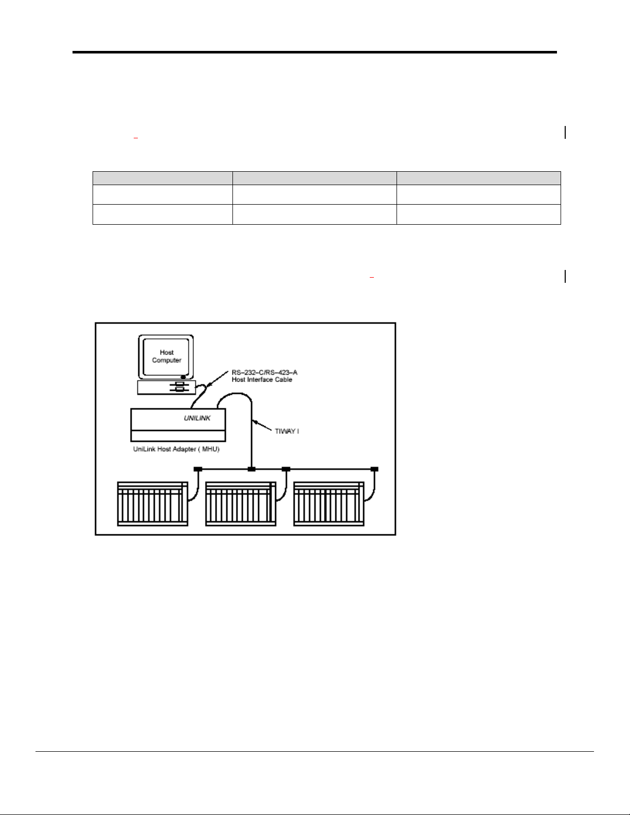
The FieldServer Siemens TIWAY I driver, hereafter simply referred to as the TIWAY driver,
can be used to emulate the host side of a Siemens Unilink Host Adaptor (UHA) using BDLC
“Host Command Protocol”. The original Siemens UHA device was used to interface other
host devices to a TIWAY I network as shown below:
232C using TIWAY BDLC “Host Adapter Command” protocol. The FieldServer can
FieldServer Mode Nodes Comments
The original Siemens UHA is really a protocol bridge in itself. It speaks “Host Command
Protocol” on the host interface which may contain embedded TIWAY primitives (commands)
and speaks Siemens TIWAY I protocol on its secondary interface. The FieldServer TIWAY I
driver emulates the UHA’s host interface when used in the server mode, however the
FieldServer does not speak Siemens TIWAY protocol and therefore cannot be used to
connect to legacy TIWAY devices directly. The driver’s use is primarily as a server to allow
legacy SCADA systems speaking “Host Command Protocol” containing TIWAY primitives to
communicate with modern PLCs speaking Modbus or other industrial protocols. The
accompanying FieldServer client driver in a configuration setup will typically be Modbus or
some other industrial protocol. The TIWAY driver’s use as a client is limited to emulating a
host to a UHA or for testing purposes.
The TIWAY driver operates in the Master Host Interface Unit ( MHIU ) mode and only
supports a limited selected set of Host Adapter commands and TIWAY primitives which are
FieldServer Technologies 1991 Tarob Court Milpitas, California 95035 USA Web:www.fieldserver.com
Tel: (408) 262-2299 Fax: (408) 262-9042 Toll_Free: 888-509-1970 email: support@fieldserver.com
Page 5
FS-8700-31 Siemens TIWAY I Page 2 of 23
listed under the Supported Host Adaptor Commands and Primitives section of the driver
factsheet.
2. Driver Scope of Supply
2.1. Supplied by FieldServer Technologies for this driver
FieldServer Technologies
PART #
Description
FS-8915-10 UTP cable (7 foot) for Ethernet connection
FS-8915-10 UTP cable (7 foot) for RS232 use
FS-8917-02 RJ45 to DB9F connector adapter
FS-8917-01 RJ45 to DB25M connection adapter
- Driver Manual.
2.2. Provided by the Supplier of 3rd Party Equipment
2.2.1. Hardware
Part # Description
2.2.2. Required 3rd Party Software
SCADA TIWAY Unilink adapter client software such as Intellution’s FIX
driver.
2.2.3. Required 3rd Party Configuration
The BDLC protocol has to be selected on any 3rd party client.
2.2.4. Optional Items
PART # Vendor/Manufacturer Description
FieldServer Technologies 1991 Tarob Court Milpitas, California 95035 USA Web:www.fieldserver.com
Tel: (408) 262-2299 Fax: (408) 262-9042 Toll_Free: 888-509-1970 email: support@fieldserver.com
Page 6
FS-8700-31 Siemens TIWAY I Page 3 of 23
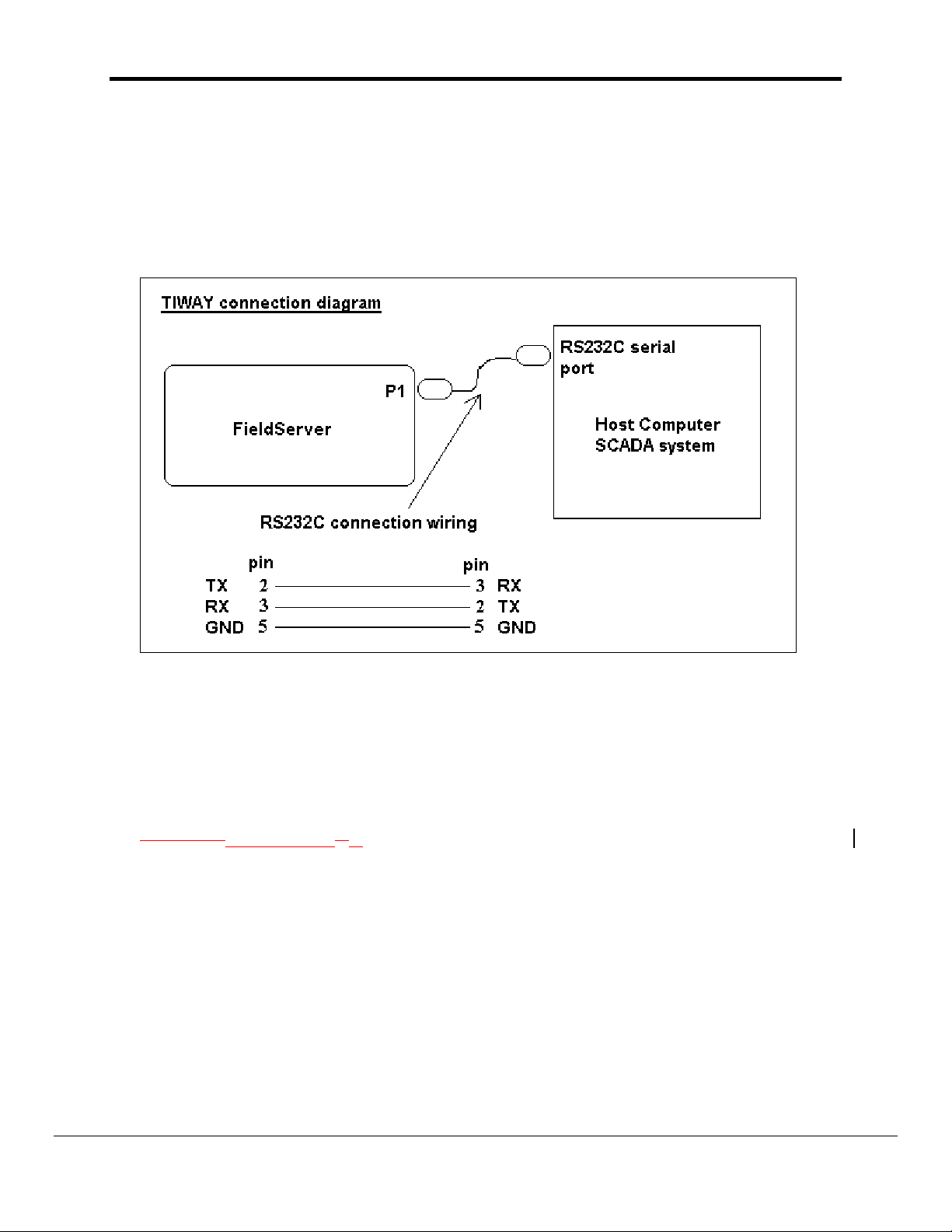
3. Hardware Connections
The FieldServer is connected to the SCADA system as shown below.
Configure the SCADA system according to manufacturer’s instructions.
3.1. Hardware Connection Tips / Hints
To be updated from testing feedback.
4. Configuring the FieldServer as a TIWAY Client
For a detailed discussion on FieldServer configuration, please refer to the FieldServer
instruction
upon the factory defaults provided in the configuration files included with the FieldServer
(See “.csv” sample files provided with the FS).
This section documents and describes the parameters necessary for configuring the
FieldServer to communicate with a TIWAY Server. The driver is normally used in the server
mode, but may be configured as a client for testing purposes.
Configuration mManual. The information that follows describes how to expand
4.1. Data Arrays/Descriptors
The configuration file tells the FieldServer about its interfaces, and the routing of data
required. In order to enable the FieldServer for TIWAY communications, the driver
independent FieldServer buffers need to be declared in the “Data Arrays” section, the
destination device addresses need to be declared in the “Client Side Nodes” section, and
FieldServer Technologies 1991 Tarob Court Milpitas, California 95035 USA Web:www.fieldserver.com
Tel: (408) 262-2299 Fax: (408) 262-9042 Toll_Free: 888-509-1970 email: support@fieldserver.com
Page 7

FS-8700-31 Siemens TIWAY I Page 4 of 23
the data required from the servers needs to be mapped in the “Client Side Map Descriptors”
section. Details on how to do this can be found below.
Note that in the tables, * indicates an optional parameter, with the bold legal value being the
default.
Section Title
Data_Arrays
Column Title Function Legal Values
Data_Array_Name Provide name for Data Array
Up to 15 alphanumeric
characters
Float, Bit, UInt16, SInt16,
Data_Array_Format
Provide data format. Each Data Array
can only take on one format.
Packed_Bit, Byte,
Packed_Byte,
Swapped_Byte
Number of Data Objects. Must be
Data_Array_Length
larger than the data storage area
required by the map descriptors for
1-10,000
the data being placed in this array.
Example
// Data Arrays
Data_Arrays
Data_Array_Name, Data_Format, Data_Array_Length,
RAW16_Data, UInt16, 20
RAW8_Data, Byte, 20
Float_Data, Float, 20
4.2. Client Side Connection Descriptions
Section Title
Connections
Column Title Function Legal Values
Specify which port the device
Port
Protocol Specify protocol used TIWAY, TIWAY_BDLC
Baud* Specify baud rate
Parity* Specify parity Even, Odd, None, Mark, Space
Data_Bits* Specify data bits 7, 8
Stop_Bits* Specify stop bits
Handshaking* Specify hardware handshaking RTS, RTS/CTS, None
Poll _Delay* Time between internal polls 0-32000 seconds, 1 second
is connected to the
FieldServer
P1-P8
110 – 115200, standard
baudrates only
1
FieldServer Technologies 1991 Tarob Court Milpitas, California 95035 USA Web:www.fieldserver.com
Tel: (408) 262-2299 Fax: (408) 262-9042 Toll_Free: 888-509-1970 email: support@fieldserver.com
Page 8

FS-8700-31 Siemens TIWAY I Page 5 of 23
Example
// Client Side Connections
Connections
Port, Protocol, Baud, Parity, Handshaking, Poll_Delay
P1, TIWAY_BDLC, 9600, None, None, 0.100s
4.3. Client Side Node Descriptors
Section Title
Nodes
Column Title Function Legal Values
Node_Name Provide name for node
Node_ID
Protocol Specify protocol used TIWAY, TIWAY_BDLC
Connection
Example
// Client Side Nodes
Nodes
Node_Name, Node_ID, Protocol, Port
PLC_01, 01, TIWAY_BDLC, P1
Secondary PLC station address to
communicate with
Specify which port the device is
connected to the FieldServer
Up to 32 alphanumeric
characters
1-254
P1-P8
4.4. Client Side Map Descriptors
4.4.1. FieldServer Related Map Descriptor Parameters
Section Title
Map Descriptors
Column Title Function Legal Values
Map_Descriptor_Name
Data_Array_Name
Data_Array_Offset
Function
FieldServer Technologies 1991 Tarob Court Milpitas, California 95035 USA Web:www.fieldserver.com
Tel: (408) 262-2299 Fax: (408) 262-9042 Toll_Free: 888-509-1970 email: support@fieldserver.com
Name of this Map
Descriptor
Name of Data Array
where data is to be stored
in the FieldServer
Starting location in Data
Array
Function of Client Map
Descriptor
Up to 32 alphanumeric
characters
One of the Data Array names
from “Data Array” section
above
0 to maximum specified in
“Data Array” section above
RDBC, WRBC, WRBX, AWT
Page 9

FS-8700-31 Siemens TIWAY I Page 6 of 23
4.4.2. Driver Related Map Descriptor Parameters
Section Title
Map Descriptors
Column Title Function Legal Values
One of the node names
specified in “Client Node
Descriptor” above
16-bit word datatypes
IE_Ladder
Variable
Constant
Word_Input
Word_Output
Timer_Cnt_Preset
Timer_Cnt_Current
Drum_Count_Preset
Loop_Status
Status_Primitive
8-bit byte datatypes
Discrete_Input
Discrete_Output
Control_Register
Discrete_Force
Control_Register_Force
Drum_Step_Preset
Drum_Step_Current
32-bit float datatypes
Loop_Gain
Loop_Reset
Loop_Rate
Loop_High_Alarm
Loop_Low_Alarm
Loop_Process_Variable
Loop_High_Process_Variable
Loop_Low_Process_Variable
Loop_Orange_Deviation
Loop_Yellow_Deviation
Loop_Sample_Rate
Loop_Set_Point
Node_Name
TIWAY_Data_Type
Name of Node to fetch
data from
Specifies fundamental
datatype to address in
PLC
FieldServer Technologies 1991 Tarob Court Milpitas, California 95035 USA Web:www.fieldserver.com
Tel: (408) 262-2299 Fax: (408) 262-9042 Toll_Free: 888-509-1970 email: support@fieldserver.com
Page 10

FS-8700-31 Siemens TIWAY I Page 7 of 23
Loop_Output
24-bit datatypes
Word_Force
Packed-bit datatypes
Discrete_Input_Packed
Discrete_Output_Packed
Control_Register_Packed
Read_Secondary_Log
Report_HIU_Config
Report_Adapter_Config
TIWAY_Host_Adapter_Cmd
TIWAY_Address_List
Preset_Step_List
Secondaries_List A list of secondary PLC
Address
Length Length of Map Descriptor 1-65535
Specifies a host adapter
command to execute
A list of PLC memory
addresses that may be
used for random read
and writes
A list of preset step
values to be used with
the Drum_Count_Preset
datatype. Each value is
tied to an address.
addresses to be used
with the Connect_ and
Disconnect_Secondaries
host adapter commands.
Starting address of read
or write block
Report_NM_Config
Soft_Reset
Reset_Adapter
Disconnect_Secondaries
Connect_Secondaries
0-65535
0-255 for loop datatypes and
Drum_Count_Preset
Maximum of 80 space
seperated values allowed.
0-255
Maximum of 80 space
seperated values allowed.
1-255
255 indicates all secondaries
from 1 to 254
0-65535
0-255 for loop datatypes and
Drum_Count_Preset
4.4.3. Timing Parameters
Section Title
Map Descriptors
Column Title Function Legal Values
Scan_Interval Rate at which data is polled ≥0.001s
FieldServer Technologies 1991 Tarob Court Milpitas, California 95035 USA Web:www.fieldserver.com
Tel: (408) 262-2299 Fax: (408) 262-9042 Toll_Free: 888-509-1970 email: support@fieldserver.com
Page 11

FS-8700-31 Siemens TIWAY I Page 8 of 23
4.4.4. Reading TIWAY data map descriptor examples
4.4.4.1. Reading data from contiguous PLC data memory locations
Map_Descriptor_Name, Data_Array_Name, Data_Array_Offset, Function, Node_name, TIWAY_Data_Type, Address, Length,
C01_RAW16_PLC01, RAW16_Data, 0, RDBC, PLC_01, IE_Ladder, 0, 10,
Scan_Interval
0s
The above map descriptor will continuously read 10 data elements starting from address 0 of type “IE_Ladder” from
PLC_01. The data will be stored in the data array called “RAW16_Data” from an offset of 0.
4.4.4.2. Reading data from random PLC data memory locations
Map_Descriptor_Name, Data_Array_Name, Data_Array_Offset, Function, Node_name, TIWAY_Data_Type, TIWAY_Address_List, Length,
C02_RAW16_PLC01, RAW16_Data, 10, RDBC, PLC_01, Variable, 5 9, 2,
Scan_Interval
0s
The above map descriptor will continuously read 2 data elements from address 5 and 9 of type “Variable” from
PLC_01. The data will be stored in the data array called “RAW16_Data” from an offset of 10. The data will be
stored at offsets 10 and 11.
4.4.4.3. Reading Drum_Count_Preset data from contiguous PLC data memory locations
Map_Descriptor_Name, Data_Array_Name, Data_Array_Offset, Function, Node_name, TIWAY_Data_Type, Address, Length,
C08_RAW16_PLC01, RAW16_Data, 70, RDBC, PLC_01, Drum_Count_Preset, 0, 5,
FieldServer Technologies 1991 Tarob Court Milpitas, California 95035 USA Web:www.fieldserver.com
Tel: (408) 262-2299 Fax: (408) 262-9042 Toll_Free: 888-509-1970 email: support@fieldserver.com
Page 12

FS-8700-31 Siemens TIWAY I Page 9 of 23
Preset_Step_List, Scan_Interval
5 8 9 33 49, 0s
The above map descriptor will continuously read 5 data elements from addresses 0-4 of type
“Drum_Count_Preset” from PLC_01. The Preset Steps associated with addresses are (address 0):5, (address 1):8,
(address 2):9, (address 3):33, and (address 4):49. The data will be stored contiguously in the data array from offset
70.
4.4.4.4. Reading Drum_Count_Preset data from random PLC data memory locations
Map_Descriptor_Name, Data_Array_Name, Data_Array_Offset, Function, Node_name, TIWAY_Data_Type, TIWAY_Address_List,
C08_RAW16_PLC01, RAW16_Data, 75, RDBC, PLC_01, Drum_Count_Preset, 5 9,
Length, Preset_Step_List, Scan_Interval
2, 42 22, 0s
The above map descriptor will continuously read 2 data elements from addresses 5 and 9 of type
“Drum_Count_Preset” from PLC_01. The Preset Steps associated with addresses are (address 5):42 and (address
9):22. The data will be stored in the data array at offset 75 and 76.
4.4.4.5. Reading secondary PLC status
Map_Descriptor_Name, Data_Array_Name, Data_Array_Offset, Function, Node_name, TIWAY_Data_Type, Length, Scan_Interval
C36_STATUS_PRIM, Status, 0, RDBC, PLC_01, Status_Primitive, 3, 0s
FieldServer Technologies 1991 Tarob Court Milpitas, California 95035 USA Web:www.fieldserver.com
Tel: (408) 262-2299 Fax: (408) 262-9042 Toll_Free: 888-509-1970 email: support@fieldserver.com
Page 13

FS-8700-31 Siemens TIWAY I Page 10 of 23
The above map descriptor will continuously read the three status values from PLC_01. The status values are
defined as follows and will be stored in the data array contiguously from an offset of zero:
Status element 1 (DD) : Operational Status
Status element 2 (EE) : Auxiliary power source status
Status element 3 (FF) : NIM Operational Status
Please refer to the TIWAY systems manual for operational values and their meanings.
4.4.5. Writing TIWAY data map descriptor examples
4.4.5.1. Writing data to contiguous PLC data memory locations
Map_Descriptor_Name, Data_Array_Name, Data_Array_Offset, Function, Node_name, TIWAY_Data_Type, Address, Length,
C12_RAW8_PLC07, RAW8_Data, 20, WRBC, PLC_07, Control_Register, 0, 10,
Scan_Interval
0s
The above map descriptor will continuously write data of type “Control_Register” to 10 PLC data memory
addresses. The data to write will be collected from the data array “RAW8_Data” from an offset of 20.
4.4.5.2. Writing data to random PLC data memory locations
Map_Descriptor_Name, Data_Array_Name, Data_Array_Offset, Function, Node_name, TIWAY_Data_Type, TIWAY_Address_List, Length,
C17_FLOAT_PLC254, FLOAT_Data, 0, WRBC, PLC_254, Loop_Gain, 5 9, 2,
Scan_Interval
0s
FieldServer Technologies 1991 Tarob Court Milpitas, California 95035 USA Web:www.fieldserver.com
Tel: (408) 262-2299 Fax: (408) 262-9042 Toll_Free: 888-509-1970 email: support@fieldserver.com
Page 14

FS-8700-31 Siemens TIWAY I Page 11 of 23
The above map descriptor will continuously write data of type “Loop_Gain” to 2 PLC data memory addresses of 5
and 9. The data to write will be collected from the data array “FLOAT_Data” from offsets 0 and 1.
4.4.5.3. Writing the same value to a block of contiguous PLC data memory locations
Map_Descriptor_Name, Data_Array_Name, Data_Array_Offset, Function, Node_name, TIWAY_Data_Type, Address, Length,
C18_FLOAT_PLC254, FLOAT_Data, 10, WRBC, PLC_254, Loop_Reset, 0, 3,
TIWAY_Fill_Block_Value, Scan_Interval
50.5, 0s
The above map descriptor will continuously write a value of 50.5 of type “Loop_Reset” to 3 contiguous PLC data
memory addresses starting from 0.
4.4.5.4. Writing Drum_Count_Preset data to contiguous PLC data memory locations
Map_Descriptor_Name, Data_Array_Name, Data_Array_Offset, Function, Node_name, TIWAY_Data_Type, Address, Length,
C08_RAW16_PLC01, RAW16_Data, 70, WRBC, PLC_01, Drum_Count_Preset, 0, 5,
Preset_Step_List, Scan_Interval
5 8 9 33 49, 0s
The above map descriptor will continuously write data of type “Drum_Count_Preset” to 5 PLC data memory
addresses. The data to write will be collected from the data array “RAW16_Data” from an offset of 70. The Preset
Steps associated with the addresses are (address 0):5, (address 1):8, (address 2):9, (address 3):33, and (address
4):49.
4.4.5.5. Writing Drum_Count_Preset data to random PLC data memory locations
Map_Descriptor_Name, Data_Array_Name, Data_Array_Offset, Function, Node_name, TIWAY_Data_Type, TIWAY_Address_List,
C08_RAW16_PLC01, RAW16_Data, 70, WRBC, PLC_01, Drum_Count_Preset, 5 9,
Length, Preset_Step_List, Scan_Interval
FieldServer Technologies 1991 Tarob Court Milpitas, California 95035 USA Web:www.fieldserver.com
Tel: (408) 262-2299 Fax: (408) 262-9042 Toll_Free: 888-509-1970 email: support@fieldserver.com
Page 15

FS-8700-31 Siemens TIWAY I Page 12 of 23
2, 33 49, 0s
The above map descriptor will continuously write data of type “Drum_Count_Preset” to 2 PLC data memory
addresses. The data to write will be collected from the data array “RAW16_Data” from an offset of 70 and 71. The
Preset Steps associated with the addresses are (address 5):33 and (address 9):49.
4.4.6. TIWAY host adapter command map descriptor examples
A number of map descriptors that send specific host adapter commands are available mainly for testing purposes
and should not be used under normal circumstances.
4.4.6.1. Read Secondary Log
Returns a list of secondary PLC stations addresses that are connected.
Map_Descriptor_Name, Data_Array_Name, Data_Array_Offset, Function, Node_name, TIWAY_Host_Adapter_Cmd, Length,
C37_READ_SEC_LOG, Secondary_Log, 0, RDBC, PLC_01, Read_Secondary_Log, 254,
Scan_Interval
0s
The above map descriptor will continuously execute the indicated host adapter command and will store the list of
connected secondary PLCs in the data array “Secondary Log” from an offset of 0. Offset 0 will correspond to
secondary address 1, offset 1 to secondary 2 up to offset 253 corresponding to secondary address 254.
4.4.6.2. Report HIU Configuration
Reports the HIU Configuration option values that was used to configure the HIU.
Map_Descriptor_Name, Data_Array_Name, Data_Array_Offset, Function, Node_name, TIWAY_Host_Adapter_Cmd, Length,
C38_REP_HIU_CONFIG, HIU_Config, 0, RDBC, PLC_01, Report_HIU_Config, 5,
Scan_Interval
0s
FieldServer Technologies 1991 Tarob Court Milpitas, California 95035 USA Web:www.fieldserver.com
Tel: (408) 262-2299 Fax: (408) 262-9042 Toll_Free: 888-509-1970 email: support@fieldserver.com
Page 16

FS-8700-31 Siemens TIWAY I Page 13 of 23
The above map descriptor will continuously execute the indicated host adapter command and will store the
following parameter values in the data array “HIU_Config”:
Offset Parameter
0 Dipswitch 1 and 2 settings
1 Config flag ( 0 = HIU not configured, 1 = HIU configured )
2 Option 01 configuration value
3 Option 02 configuration value
4 Option 03 configuration value
4.4.6.3. Report Adapter Configuration
Reports the Adapter Configuration option values that was used to configure the adapter.
Map_Descriptor_Name, Data_Array_Name, Data_Array_Offset, Function, Node_name, TIWAY_Host_Adapter_Cmd, Length,
C39_REP_ADAP_CONFIG, Adapter_Config, 0, RDBC, PLC_01, Report_Adapter_Config, 6,
Scan_Interval
0s
The above map descriptor will continuously execute the indicated host adapter command and will store the
following parameter values in the data array “Adapter_Config”:
Offset Parameter
0 Dipswitch 1 and 2 settings
1 Config flag ( 0 = Adapter not configured, 1 = Adapter configured )
2 Option 01 configuration value
3 Option 02 configuration value
4 Option 03 configuration value
5 Option 04 configuration value
4.4.6.4. Report Network Manager Configuration
Reports the Network Manager option values that was used to configure the network manager.
Map_Descriptor_Name, Data_Array_Name, Data_Array_Offset, Function, Node_name, TIWAY_Host_Adapter_Cmd, Length,
FieldServer Technologies 1991 Tarob Court Milpitas, California 95035 USA Web:www.fieldserver.com
Tel: (408) 262-2299 Fax: (408) 262-9042 Toll_Free: 888-509-1970 email: support@fieldserver.com
Page 17

FS-8700-31 Siemens TIWAY I Page 14 of 23
C40_REP_NM_CONFIG, Nm_Config, 0, RDBC, PLC_01, Report_NM_Config, 16,
Scan_Interval
0s
The above map descriptor will continuously execute the indicated host adapter command and will store the
following parameter values in the data array “Nm_Config”:
Offset Parameter
0 Dipswitch 1 and 2 settings
1 Config flag ( 0 = Network Manager not configured, 1 = Network Manager configured )
2 Option 01 configuration value
3 Option 02 configuration value
4 Option 03 configuration value
5 Option 04 configuration value
6 Option 05 configuration value
7 Option 06 configuration value
8 Option 07 configuration value
9 Option 08 configuration value
10 Option 09 configuration value
11 Option 0A configuration value
12 Option 0B configuration value
13 Option 0C configuration value
14 Option 0D configuration value
15 Option 0E configuration value
4.4.6.5. Soft Reset
Forces the UNILINK Host Adapter to do a software reset.
Map_Descriptor_Name, Data_Array_Name, Data_Array_Offset, Function, Node_name, TIWAY_Host_Adapter_Cmd, Length
C41_SOFT_RESET, Cmd_Triggers, 0, AWT, PLC_01, Soft_Reset, 1
The above map descriptor will execute the indicated host adapter command once every time a value is written to
the data array “Cmd_Triggers” at offset 0.
FieldServer Technologies 1991 Tarob Court Milpitas, California 95035 USA Web:www.fieldserver.com
Tel: (408) 262-2299 Fax: (408) 262-9042 Toll_Free: 888-509-1970 email: support@fieldserver.com
Page 18

FS-8700-31 Siemens TIWAY I Page 15 of 23
4.4.6.6. Reset Adapter
Forces the UNILINK Host Adapter to do a hardware reset.
Map_Descriptor_Name, Data_Array_Name, Data_Array_Offset, Function, Node_name, TIWAY_Host_Adapter_Cmd, Length
C42_RESET_ADAPTER, Cmd_Triggers, 1, AWT, PLC_01, Reset_Adapter, 1
The above map descriptor will execute the indicated host adapter command once every time a value is written to
the data array “Cmd_Triggers” at offset 1.
4.4.6.7. Disconnect Secondaries
Disconnect Secondary PLCs from the network.
Map_Descriptor_Name, Data_Array_Name, Data_Array_Offset, Function, Node_name, TIWAY_Host_Adapter_Cmd, Length,
C43_DISC_SECDS, Cmd_Triggers, 2, AWT, PLC_01, Disconnect_Secondaries, 1,
Secondaries_List
1 9 147 254
The above map descriptor will execute the indicated host adapter command once every time a value is written to
the data array “Cmd_Triggers” at offset 2. Secondaries 1 9 147 and 254 will be disconnected from the network.
To disconnect all secondaries, use only one value of 255 in the Secondaries_List field.
4.4.6.8. Connect Secondaries
Disconnect Secondary PLCs from the network.
Map_Descriptor_Name, Data_Array_Name, Data_Array_Offset, Function, Node_name, TIWAY_Host_Adapter_Cmd, Length,
C45_CONNECT_SECDS, Cmd_Triggers, 4, AWT, PLC_01, Connect_Secondaries, 1,
Secondaries_List
1 9 147 254
FieldServer Technologies 1991 Tarob Court Milpitas, California 95035 USA Web:www.fieldserver.com
Tel: (408) 262-2299 Fax: (408) 262-9042 Toll_Free: 888-509-1970 email: support@fieldserver.com
Page 19

FS-8700-31 Siemens TIWAY I Page 16 of 23
The above map descriptor will execute the indicated host adapter command once every time a value is written to
the data array “Cmd_Triggers” at offset 4. Secondaries 1 9 147 and 254 will be connected to the network.
To connect all secondaries, use only one value of 255 in the Secondaries_List field.
FieldServer Technologies 1991 Tarob Court Milpitas, California 95035 USA Web:www.fieldserver.com
Tel: (408) 262-2299 Fax: (408) 262-9042 Toll_Free: 888-509-1970 email: support@fieldserver.com
Page 20

FS-8700-931 Siemens TIWAY I Page 17 of 23
5. Configuring the FieldServer as a TIWAY Server
For a detailed discussion on FieldServer configuration, please refer to the FieldServer
instruction
to expand upon the factory defaults provided in the configuration files included with the
FieldServer (See “.csv” files on the driver diskette).
This section documents and describes the parameters necessary for configuring the
FieldServer to communicate with a TIWAY Client.
The configuration file tells the FieldServer about its interfaces, and the routing of data
required. In order to enable the FieldServer for TIWAY communications, the driver
independent FieldServer buffers need to be declared in the “Data Arrays” section, the
FieldServer virtual node(s) needs to be declared in the “Server Side Nodes” section, and the
data to be provided to the clients needs to be mapped in the “Server Side Map Descriptors”
section. Details on how to do this can be found below.
Note that in the tables, * indicates an optional parameter, with the bold legal value being the
default.
Configuration mManual (Virtual PLC). The information that follows describes how
5.1. Server Side Connection Descriptors
Section Title
Connections
Column Title Function Legal Values
Port
Protocol
Baud* Specify baud rate
Parity* Specify parity
Data_Bits*
Stop_Bits*
Handshaking* Specify hardware handshaking RTS, RTS/CTS, None
Server_Hold_Timeout*
Specify which port the device is
connected to the FieldServer
Specify protocol used TIWAY, TIWAY_BDLC
Specify data bits 7, 8
Specify stop bits
Specifies time FieldServer will
reserve server side connection
while waiting for the Client side
to update data in Data_Array (if
necessary)
P1-P8
110 – 115200, standard
baud rates only
Even, Odd, None, Mark,
Space
1
>1.0s
FieldServer Technologies 1991 Tarob Court Milpitas, California 95035 USA Web:www.fieldserver.com
Tel: (408) 262-2299 Fax: (408) 262-9042 Toll_Free: 888-509-1970 email: support@fieldserver.com
Page 21

FS-8700-931 Siemens TIWAY I Page 18 of 23
Example
// Server Side Connections
Connections
Port, Protocol, Baud, Parity, Handshaking,
P1, TIWAY_BDLC, 9600, None, None,
5.2. Server Side Node Descriptors
Section Title
Nodes
Column Title Function Legal Values
Node_Name Provide name for node
Node_ID
Secondary PLC station address
of physical server node
Protocol Specify protocol used TIWAY, TIWAY_BDLC
Specifies time FieldServer will
reserve server side connection
Server_Hold_Timeout*
while waiting for the Client side
to update data in Data_Array (if
necessary)
Example
// Server Side Nodes
Nodes
Node_Name, Node_ID, Protocol
PLC_01, 01, TIWAY_BDLC
* Note that no connection information such as the Port is necessary on Server side.
Up to 32 alphanumeric
characters
1-254
>1.0s
FieldServer Technologies 1991 Tarob Court Milpitas, California 95035 USA Web:www.fieldserver.com
Tel: (408) 262-2299 Fax: (408) 262-9042 Toll_Free: 888-509-1970 email: support@fieldserver.com
Page 22

FS-8700-931 Siemens TIWAY I Page 19 of 23
5.3. Server Side Map Descriptors
5.3.1. FieldServer Specific Map Descriptor Parameters
Section Title
Map Descriptors
Column Title Function Legal Values
Map_Descriptor_Name Name of this Map Descriptor
Name of Data Array where
Data_Array_Name
Data_Array_Offset
Function
Server_Hold_Timeout*
data is to be stored in the
FieldServer
Starting location in Data
Array
Function of Server Map
Descriptor
Specifies time FieldServer
will reserve server side
connection while waiting for
the Client side to update
data in Data_Array (if
necessary)
Up to 32 alphanumeric
characters
One of the Data Array
names from “Data Array”
section above
0 to maximum specified in
“Data Array” section above
Server
>1.0s
5.3.2. Driver Specific Map Descriptor Parameters
Section Title
Map Descriptors
Column Title Function Legal Values
One of the node names
specified in “Client Node
Descriptor” above
16-bit word datatypes
IE_Ladder
Variable
Constant
Word_Input
Word_Output
Timer_Cnt_Preset
Timer_Cnt_Current
Drum_Count_Preset
Loop_Status
Status_Primitive
8-bit byte datatypes
Discrete_Input
Discrete_Output
Node_Name
TIWAY_Data_Type
Name of Node to fetch data
from
Specifies fundamental
datatype represented by
the PLC
FieldServer Technologies 1991 Tarob Court Milpitas, California 95035 USA Web:www.fieldserver.com
Tel: (408) 262-2299 Fax: (408) 262-9042 Toll_Free: 888-509-1970 email: support@fieldserver.com
Page 23

FS-8700-931 Siemens TIWAY I Page 20 of 23
Control_Register
Discrete_Force
Control_Register_Force
Drum_Step_Preset
Drum_Step_Current
32-bit float datatypes
Loop_Gain
Loop_Reset
Loop_Rate
Loop_High_Alarm
Loop_Low_Alarm
Loop_Process_Variable
Loop_High_Process_Variable
Loop_Low_Process_Variable
Loop_Orange_Deviation
Loop_Yellow_Deviation
Loop_Sample_Rate
Loop_Set_Point
Loop_Output
24-bit datatypes
Word_Force
Packed-bit datatypes
Discrete_Input_Packed
Discrete_Output_Packed
Control_Register_Packed
A list of preset step values
0-255
Maximum of 80 space
seperated values allowed.
Preset_Step_List
to be used with the
Drum_Count_Preset
datatype. Each value is tied
to an address.
0-65535
0-255 for loop datatypes and
Drum_Count_Preset
Address
Starting address of read or
write block
Length Length of Map Descriptor 1 - 65535
FieldServer Technologies 1991 Tarob Court Milpitas, California 95035 USA Web:www.fieldserver.com
Tel: (408) 262-2299 Fax: (408) 262-9042 Toll_Free: 888-509-1970 email: support@fieldserver.com
Page 24

FS-8700-31 Siemens TIWAY I Page 21 of 23
5.3.3. Serving TIWAY data map descriptor example
Map_Descriptor_Name, Data_Array_Name, Data_Array_Offset, Function, Node_name, TIWAY_Data_Type, Address, Length
S01_RAW16_PLC0, RAW16_Data, 0, Server, PLC_01, IE_Ladder, 0, 10
The above map descriptor serves 10 data elements starting from address 0 of type “IE_Ladder” for PLC_01.
5.3.4. Serving Drum_Count_Preset TIWAY data map descriptor example
Map_Descriptor_Name, Data_Array_Name, Data_Array_Offset, Function, Node_name, TIWAY_Data_Type, Address, Length,
S10_RAW16_PLC01, RAW16_Data, 71, Server, PLC_01, Drum_Count_Preset, 0, 4,
Preset_Step_List
3 5 9 167
The above map descriptor serves 4 data elements starting from address 0 of type “Drum_Count_Preset” for
PLC_01. Each address location is contiguously associated with a preset step value from the Preset_Step_List field.
5.3.5. Serving PLC status data map descriptor example
Map_Descriptor_Name, Data_Array_Name, Data_Array_Offset, Function, Node_name, TIWAY_Data_Type, Length
S36_PRIM_STATUS, Status, 0, Server, PLC_01, Status_Primitive, 3
The above map descriptor serves 3 status data elements for PLC_01 in the data array “Status” starting from offset
0.
FieldServer Technologies 1991 Tarob Court Milpitas, California 95035 USA Web:www.fieldserver.com
Tel: (408) 262-2299 Fax: (408) 262-9042 Toll_Free: 888-509-1970 email: support@fieldserver.com
Page 25

FS-8700-31 Siemens TIWAY I Page 22 of 23
6. Advanced Topics
None.
7. Driver Notes
None.
8. Troubleshooting tips
8.1. Connection Tips & Hints
None.
FieldServer Technologies 1991 Tarob Court Milpitas, California 95035 USA Web:www.fieldserver.com
Tel: (408) 262-2299 Fax: (408) 262-9042 Toll_Free: 888-509-1970 email: support@fieldserver.com
Page 26

FS-8700-31 Siemens TIWAY I Page 23 of 23
Revision History
Date
Driver
Version
04/24/03 1.00a 0 DR Created
8/13/03 1.00a 1 JD Format Changes
11/20/03 1.00a 2 JD Formatting Changes
Document
Revision
Resp
Comment
FieldServer Technologies 1991 Tarob Court Milpitas, California 95035 USA Web:www.fieldserver.com
Tel: (408) 262-2299 Fax: (408) 262-9042 Toll_Free: 888-509-1970 email: support@fieldserver.com
 Loading...