

Page 1

Driver Version:
1.02
A Sierra Monitor Company
Driver Manual
(Supplement to the FieldServer Instruction Manual)
FS-8700-19 Metasys N2
APPLICABILITY & EFFECTIVITY
Effective for all systems manufactured after May 1, 2001
Document Revision: 22
Page 2

FS-8700-19_Metasys_N2 Driver Manual Table of Contents
TABLE OF CONTENTS
1.
Metasys N2 Description ................................................................................................. 3
2.
Driver Scope of Supply .................................................................................................. 4
2.1.
Supplied by FieldServer Technologies for this driver.................................................. 4
2.2.
Provided by the Supplier of 3rd Party Equipment ........................................................ 4
2.2.1. Hardware................................................................................................................ 4
2.2.2. Required 3rd Party Software.................................................................................... 4
2.2.3. Required 3rd Party Configuration............................................................................. 4
3.
Hardware Connections .................................................................................................. 5
3.1.
Hardware Connection Tips / Hints.............................................................................. 5
4.
Configuring the FieldServer as a Metasys N2 Client ................................................... 6
4.1.
Data Arrays/Descriptors............................................................................................. 6
4.2.
Client Side Connection Descriptions .......................................................................... 7
4.3.
Client Side Node Descriptors ..................................................................................... 8
4.4.
Client Side Map Descriptors....................................................................................... 8
4.4.1. FieldServer Related Map Descriptor Parameters.................................................... 8
4.4.2. Driver Related Map Descriptor Parameters............................................................. 9
4.4.3. Timing Parameters ................................................................................................13
4.4.4. Map Descriptor Example 1 – N2Open....................................................................14
4.4.5. Map Descriptor Example 2 - VMA..........................................................................14
4.4.6. Map Descriptor Example 3 - DX9100.....................................................................15
5.
Configuring the FieldServer as a Metasys N2 Server .................................................16
5.1.
Server Side Connection Descriptors .........................................................................16
5.2.
Server Side Node Descriptors...................................................................................17
5.3.
Server Side Map Descriptors ....................................................................................18
5.3.1. FieldServer Specific Map Descriptor Parameters...................................................18
5.3.2. Driver Specific Map Descriptor Parameters ...........................................................18
5.3.3. Map Descriptor Example........................................................................................19
Appendix A. Advanced Topics...........................................................................................20
Appendix A.1. Writing to DX9100 Binary Outputs................................................................20
Appendix A.2. Managing Analog Inputs and Outputs for DX9100. ......................................21
Appendix B. Troubleshooting tips.....................................................................................22
Appendix B.1. Connection Tips & Hints...............................................................................22
Appendix B.2. Offline Behavior ...........................................................................................22
Appendix B.3. Tip on Overrides ..........................................................................................22
Appendix C. Setting up FS-B20 for RS-485.......................................................................23
Appendix C.1. Jumper Settings:..........................................................................................23
Appendix C.2. Hardware connections .................................................................................25
Appendix C.3. Configuration Settings..................................................................................25
Appendix D. Memory Maps ................................................................................................26
Appendix D.1. Metasys DX9100 Memory Map....................................................................26
Appendix D.2. Metasys DC9100 Memory Map....................................................................33
Appendix D.3. Metasys TC9100 Memory Map ....................................................................40
Appendix E. Error Messages .............................................................................................50
FieldServer Technologies 1991 Tarob Court Milpitas, California 95035 USA Web:www.fieldserver.com
Tel: (408) 262-2299 Fax: (408) 262-2296 Toll_Free: 888-509-1970 email: support@fieldserver.com
Page 3

FS-8700-19_Metasys_N2 Driver Manual Page 3 of 51
1. Metasys N2 Description
The Metasys N2 network supports communications with a diverse range of devices. Many N2
compatible devices use their own version of the protocol and care must be taken to ensure that
the device of interest is covered by the FieldServer implementation.
At present the FieldServer N2 driver will support communications with the following devices or
device classes when acting as a Client:
1. N2Open-compliant devices. N2Open is a published N2-compatible protocol enabling 3rd
party device vendors to integrate with N2.
2. VMA 1400 series (with restrictions, as described in this document)
3. DX9100 and XT9100
When acting as a Server, the FieldServer N2 driver can emulate an N2Open device only.
FieldServer Technologies 1991 Tarob Court Milpitas, California 95035 USA Web:www.fieldserver.com
Tel: (408) 262-2299 Fax: (408) 262-2296 Toll_Free: 888-509-1970 email: support@fieldserver.com
Page 4

FS-8700-19_Metasys_N2 Driver Manual Page 4 of 51
2. Driver Scope of Supply
2.1. Supplied by FieldServer Technologies for this driver
FieldServer Technologies
PART #
FS-8915-10 UTP cable (7 foot) for Ethernet connection
FS-8915-10 UTP cable (7 foot) for RS-232 use
FS-8917-02 RJ45 to DB9F connector adapter
FS-8917-01 RJ45 to DB25M connection adapter
SPA59132 RS-485 connection adapter
FS-8700-19 Driver Manual.
Description
2.2. Provided by the Supplier of 3rd Party Equipment
2.2.1. Hardware
PART # DESCRIPTION
Metasys NCU or other device
2.2.2. Required 3rd Party Software
Depending on application, JCI software may be necessary
2.2.3. Required 3rd Party Configuration
Depending on application, third party devices may need configuration
FieldServer Technologies 1991 Tarob Court Milpitas, California 95035 USA Web:www.fieldserver.com
Tel: (408) 262-2299 Fax: (408) 262-2296 Toll_Free: 888-509-1970 email: support@fieldserver.com
Page 5
FS-8700-19_Metasys_N2 Driver Manual Page 5 of 51
06
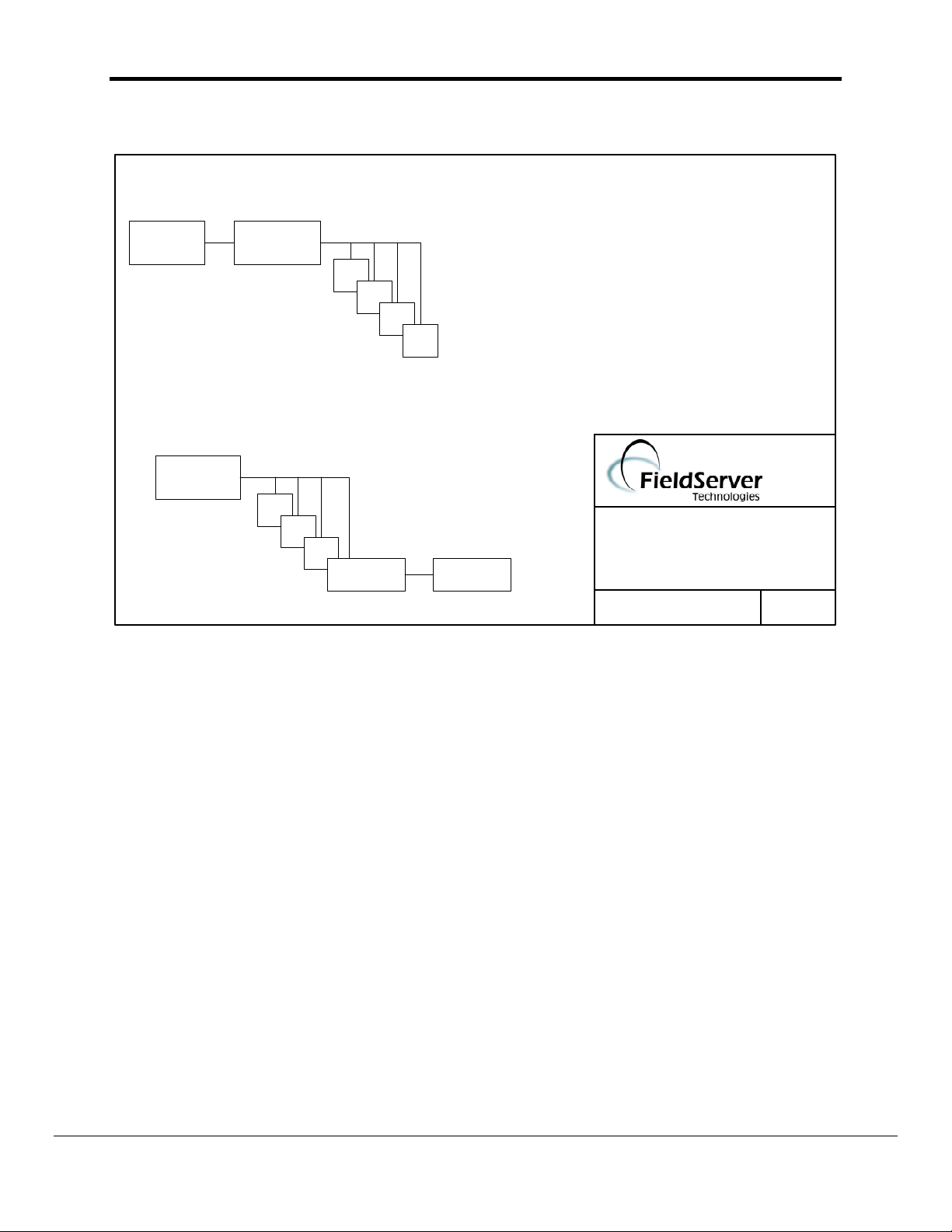
3. Hardware Connections
FieldServer as a Client
3rd Party
System
FieldServer
N2 bus
N2 devices
FieldServer as a Server
NCM, N30 or
other N2 client
N2 bus
N2 devices
FieldServer
3rd Party
System
3.1. Hardware Connection Tips / Hints
MetasysN2
CONNECTION DIAGRAM
BASE NAME:
FILE NAME: FS-8700-19
(408)-262-2299
DATE: 05/31/
BY: MC
When using the FS-X40 ensure that the FieldServer is connected to the network using one
or both of the RS-485 ports marked R1 and R2. If more ports are required, P1-P8 may be
used in conjunction with an RS-232-to-RS-485 converter.
When using the FS-X20, ensure that the serial port is configured as an RS-485 port. Refer
to Appendix B.3 for more information.
Only one N2 Client may be connected to a N2 network. If the FieldServer is to act as a
Client, ensure that no other Clients are connected to the same N2 network.
Note: Interceptor mode is no longer supported for this driver.
FieldServer Technologies 1991 Tarob Court Milpitas, California 95035 USA Web:www.fieldserver.com
Tel: (408) 262-2299 Fax: (408) 262-2296 Toll_Free: 888-509-1970 email: support@fieldserver.com
Page 6

FS-8700-19_Metasys_N2 Driver Manual Page 6 of 51
4. Configuring the FieldServer as a Metasys N2 Client
For a detailed discussion on FieldServer configuration, please refer to the FieldServer
Configuration manual. The information that follows describes how to expand upon the factory
defaults provided in the configuration files included with the FieldServer (See “.csv” sample files
provided with the FieldServer).
This section documents and describes the parameters necessary for configuring the FieldServer
to communicate with a Metasys N2 Server.
4.1. Data Arrays/Descriptors
The configuration file defines the FieldServer interfaces, and the data routing required. In
order to enable the FieldServer for Metasys N2 communications, the driver independent
FieldServer buffers need to be declared in the “Data Arrays” section, the destination device
addresses need to be declared in the “Client Side Nodes” section, and the data required
from the Servers needs to be mapped in the “Client Side Map Descriptors” section.
Note that in the tables, * indicates an optional parameter, with the bold legal value being the
default value. Where only one legal value is given, no other values for that parameter are
allowed.
Section Title
Data_Arrays
Column Title Function Legal Values
Data_Array_Name Provide name for Data Array
Data_Array_Format
Provide data format. Each Data Array
can only take on one format.
Number of Data Objects. Must be
Data_Array_Length
larger than the data storage area
required by the Map Descriptors for
the data being placed in this array.
Example
// Data Arrays
Data_Arrays
Data_Array_Name, Data_Format, Data_Array_Length
DA_AI_01, UInt16, 200
DA_AO_01, UInt16, 200
DA_DI_01, Bit, 200
DA_DO_01, Bit, 200
Up to 15 alphanumeric
characters
Float, Bit, UInt16, SInt16,
Packed_Bit, Byte,
Packed_Byte,
Swapped_Byte
1-10,000
FieldServer Technologies 1991 Tarob Court Milpitas, California 95035 USA Web:www.fieldserver.com
Tel: (408) 262-2299 Fax: (408) 262-2296 Toll_Free: 888-509-1970 email: support@fieldserver.com
Page 7

FS-8700-19_Metasys_N2 Driver Manual Page 7 of 51
4.2. Client Side Connection Descriptions
Section Title
Connections
Column Title Function Legal Values
Port
Protocol Specify protocol used Metasys_N2
Baud* Specify baud rate
Parity* Specify parity
Data_Bits* Specify data bits
Stop_Bits* Specify stop bits
Handshaking* Specify hardware handshaking
Poll _Delay* Time between internal polls
Line_Drive_On*
Line_Drive_Off*
Example
// Client Side Connections
Connections
Port, Protocol
R1, Metasys_N2
Specify which port the device is
connected to the FieldServer
Duration of RTS assert before
start of transmission
Duration of RTS assert after
end of transmission
P1-P8, R1-R21
9600
None
8
1
None
0
0.001s
0.000s
1
Not all ports shown are necessarily supported by the hardware. Consult the appropriate Instruction
manual for details of the ports available on specific hardware.
FieldServer Technologies 1991 Tarob Court Milpitas, California 95035 USA Web:www.fieldserver.com
Tel: (408) 262-2299 Fax: (408) 262-2296 Toll_Free: 888-509-1970 email: support@fieldserver.com
Page 8

FS-8700-19_Metasys_N2 Driver Manual Page 8 of 51
4.3. Client Side Node Descriptors
Section
Title
Nodes
Column
Title
Node_Name Provide name for node
Node_ID Station address of physical Server node 1-255
Protocol Specify protocol used Metasys_N2
Connection
Specify which port the device is connected to the
FieldServer
Identify type of device
If this parameter is omitted the driver treats the
configuration as a N2Open configuration and marks
the Node_Type as N2OpenClient when using Ruinet
Node_Type
to check the Node parameters.
If the Node_Type is specified as N2Open then the
driver still acts as N2 Open configuration but some
legacy port expander functionality used in some
legacy advanced configuration is enabled.
Example
// Client Side Nodes
Nodes
Node_Name, Node_ID, Protocol, Connection, Node_Type
PLC 1, 1, Metasys_N2, P8, VMA
Function Legal Values
Up to 32
alphanumeric
characters
P1-P8, R1-R2
1
N2OpenClient,
DX9100, VMA,
N2Open
4.4. Client Side Map Descriptors
4.4.1. FieldServer Related Map Descriptor Parameters
Column Title Function Legal Values
Map_Descriptor_Name
Name of this Map
Descriptor
Name of Data Array
Data_Array_Name
where data is to be
stored in the FieldServer
Data_Array_Offset
Function
Starting location in Data
Array
Function of Client Map
Descriptor
FieldServer Technologies 1991 Tarob Court Milpitas, California 95035 USA Web:www.fieldserver.com
Tel: (408) 262-2299 Fax: (408) 262-2296 Toll_Free: 888-509-1970 email: support@fieldserver.com
Up to 32 alphanumeric
characters
One of the Data Array names
from “Data Array” section
above
0 to maximum specified in
“Data Array” section above
RDBC, WRBC, WRBX
Page 9

FS-8700-19_Metasys_N2 Driver Manual Page 9 of 51
4.4.2. Driver Related Map Descriptor Parameters
4.4.2.1. N2Open Map Descriptor Parameters
Column Title Function Legal Values
One of the node names
Node_Name Name of Node to fetch data from
Data_Type Data type
Length Length of Map Descriptor 1
Address Starting address of read block 1-256
Used to specify an N2-specific
MN2_Function*
function, e.g. COS. See
description below.
Used to specify the attribute if an
MN2_Attribute*
attribute other than Current Value
is to be accessed. See attribute
table below
specified in “Client Node
Descriptor” above
If the vendor device lists a
point as BD then use
Data_Type=Byte.
If the vendor device lists a
point as ADI then use
Data_Type=Integer.
If the vendor device lists a
point as ADF then use
Data_Type=Float_Reg.
AI, AO, DI, DO,
Float_Reg, Integer, Byte
COS, Override, Release
See
N2Open Attribute Table
FieldServer Technologies 1991 Tarob Court Milpitas, California 95035 USA Web:www.fieldserver.com
Tel: (408) 262-2299 Fax: (408) 262-2296 Toll_Free: 888-509-1970 email: support@fieldserver.com
Page 10

FS-8700-19_Metasys_N2 Driver Manual Page 10 of 51
N2Open Attribute Table
Data Type Attribute No. Attribute
Analog Input
Binary Input
Analog Output
Binary Output
Internal Float
Internal Integer
Internal Byte
1
2
3
4
5
6
7
8
1
2
1
2
3
1
2
3
4
5
1
2
1
2
1
2
Object Configuration
Object Status
Analog Input Value
Low Alarm Limit
High Alarm Limit
Low Warn Limit
High Warn Limit
Differential
Object Configuration
Object Status
Object Configuration
Object Status
Current Value
Object Configuration
Object Status
Minimum On-Time
Minimum Off-Time
Maximum Cycles/Hour
Object Status
Current Value
Object Status
Current Value
Object Status
Current Value
Using Change of State (COS) – N2Open
If a large number of points are to be monitored, optimal efficiency is achieved by
using the COS mechanism instead of reading each individual point directly. A
N2Open device responds to a COS poll with a change record if a change has taken
place. On startup the device will report the state of all its points when it receives a
COS poll.
Two kinds of Map Descriptors are required for every node that is to be monitored
using COS:
A COS polling Map Descriptor with Function set to COS_Poll.
A COS_Read (i.e. Function set to COS_Read) Map Descriptor for every point
on that node that is to be monitored. Any COS records received will be stored to
the matching Map Descriptor data location.
Note that the COS_Read Map Descriptor has an optional scan_interval. If a value is
set the Map Descriptor will poll at that rate in addition to receiving COS data. This
can be used if the values are to be refreshed continually even if they don’t change. If
the scan_interval is not configured (through omitting the column, or by setting the
value to ‘-‘) the COS_Read Map Descriptor will not cause active polls once the value
has been initialized. See 4.4.4 for example.
Important Note on COS Operation in N2Open
Please be aware that N2Open devices will only report value changes under the
following conditions:
FieldServer Technologies 1991 Tarob Court Milpitas, California 95035 USA Web:www.fieldserver.com
Tel: (408) 262-2299 Fax: (408) 262-2296 Toll_Free: 888-509-1970 email: support@fieldserver.com
Page 11

FS-8700-19_Metasys_N2 Driver Manual Page 11 of 51
Point Type Conditions that will trigger a COS report
point status change (e.g. override)
AI
AO
BI, BO
ADI, ADF, BD
change in alarm or warning status
NB: no value changes within the normal band are reported by COS!
point status change (e.g. override)
NB: no value changes within the normal band are reported by COS!
point status change (e.g. override); includes current value (On/Off)
none; COS cannot be used with internal data types.
Using Override and Release – N2Open
It is not normally necessary to use the Override command explicitly as the
FieldServer automatically uses this command when the Current Value attribute of a
point is written. For any other attribute it uses the Write command. It will sometimes
be necessary to send a Release command to an overridden point, however. To do
this, a Map Descriptor must be configured with Function set to wrbx and
MN2_Function set to Release. Then, when any value is stored to the Map
Descriptor data location, the Release command will be sent to the N2Open point
specified by the Map Descriptor.
4.4.2.2. VMA Map Descriptor Parameters
Column Title Function Legal Values
One of the node names
specified in “Client Node
Descriptor” above
Node_Name
Name of Node to fetch
data from
AI, AO, DI, DO, Driver
Data_Type Data type
(used for ADF, ADI and
BD)
Length Length of Map Descriptor 1
Address
Starting address of read
block
1-256
Data type specifier to be
MN2_Type
set when Data_Type has
5-7
been set to Driver
ADI, ADF and BD types: using the “Driver” Data_Type and MN2_Type fields
The VMA protocol uses a byte value to specify the data types. The standard types
AI, AO, DI and DO correspond to a byte value of 1 through 4 respectively. The types
ADF, ADI and BD are believed to correspond to a byte value of 5 through 7
respectively. If the user wishes to use any other type value based on knowledge of a
particular VMA configuration, then that value may also be specified here. Refer to
Section 4.4.5 for a specific example.
FieldServer Technologies 1991 Tarob Court Milpitas, California 95035 USA Web:www.fieldserver.com
Tel: (408) 262-2299 Fax: (408) 262-2296 Toll_Free: 888-509-1970 email: support@fieldserver.com
Page 12

FS-8700-19_Metasys_N2 Driver Manual Page 12 of 51
Driver Data_Type
MN2_Type values
Point Type Known Value
2
Suggested Value
3
AI 1
AO 2
BI 3
BO 4
ADF 5
ADI 6
BD 7
If a large number of points are to be monitored, optimal efficiency is achieved by
using the COS mechanism instead of reading each individual point directly. An
N2Open device responds to a COS poll with a change record if a change has taken
place. On startup the device will report the state of all its points when it receives a
COS poll.
Three kinds of Map Descriptors are required for every node that is to be monitored
using COS:
• A COS initialization Map Descriptor with Function set to ARS and
MN2_Function set to COS_Enable. This Map Descriptor enables COS polling
of those points on the VMA for which Passive Map Descriptors exist.
• A COS polling Map Descriptor with Function set to rdbc and MN2_Function set
to COS.
• A Passive (i.e. Function set to Passive) Map Descriptor for every point on that
node that is to be monitored. Any COS records received will be stored to the
matching Map Descriptor data location.
See example in Section 4.4.5
Using Override and Release - VMA
It is normally not necessary to use the Override command explicitly as the
FieldServer automatically uses this command when the Current Value attribute of a
point is written. For any other attribute it uses the Write command. It will sometimes
be necessary to send a Release command to an overridden point, however. To do
this, a Map Descriptor must be configured with Function set to wrbx and
MN2_Function set to Release. Then, when any value is stored to the Map
Descriptor data location, the Release command will be sent to the VMA point
specified by the Map Descriptor.
Note: The VMA Release function only works for analog and binary inputs (AI and
BI). Outputs may be restored to their original value using an explicit write command.
2
For information only. Do not use Driver type for these, but specify AI, AO, BI or BO directly in the Data_Type field.
3
These values are believed to be correct for the corresponding point types, but no guarantee can be given at this time.
FieldServer Technologies 1991 Tarob Court Milpitas, California 95035 USA Web:www.fieldserver.com
Tel: (408) 262-2299 Fax: (408) 262-2296 Toll_Free: 888-509-1970 email: support@fieldserver.com
Page 13

FS-8700-19_Metasys_N2 Driver Manual Page 13 of 51
4.4.2.3. DX9100 Map Descriptor Parameters
Column Title Function Legal Values
One of the node names
specified in “Client Node
Descriptor” above
Node_Name
Name of Node to fetch
data from
Length Length of Map Descriptor 1
Address
Starting address of read
block
0 - 2397
For DX9100 addresses please refer to the DX9100 user documentation. This lists
the name, function (read/write) and data format of all available points. Alternatively,
obtain assistance from FieldServer Technical Support.
4.4.3. Timing Parameters
Column Title Function Legal Values
Scan_Interval Rate at which data is polled ≥0.001s
FieldServer Technologies 1991 Tarob Court Milpitas, California 95035 USA Web:www.fieldserver.com
Tel: (408) 262-2299 Fax: (408) 262-2296 Toll_Free: 888-509-1970 email: support@fieldserver.com
Page 14
Release function used in conjunction with
wrbx. If the Data Array value specified in this
Map Descriptor is changed, then a Release
command is sent to the specified point.
Node_name Address Data_Type Scan_Interval
MN2_Function
,
COS_Read Map
Descriptor sets point type
the same as normal read
Map Descriptor. Optional
scan_interval.
COS_Poller Map
Descriptor. This only
specifies the
Function, Node and
Scan_Interval.
Tel: (408) 262-2299 Fax: (408) 262-2296 Toll_Free: 888-509-1970 email: support@fieldserver.com
FieldServer Technologies 1991 Tarob Court Milpitas, California 95035 USA Web:www.fieldserver.com
4.4.4. Map Descriptor Example 1 – N2Open
Normal read Map Descriptor.
Note RDBC function,
Data_Type and Address
specification.
FS-8700-19_Metasys_N2 Driver Manual Page 14 of 51
// Client Side Map Descriptors
Map_Descriptors
Map_Descriptor_Name, DA_Name, DA_Offset, Function,
COS_POLLER, DA_COS, 0, COS_Poller, -, Node_A, -, -, 30s
AI_READ, DA_AI3, 0, RDBC, -, Node_A, 1, Ana_Input 5s
BI_BY_COS, DA_BI, 3, COS_Read, -, Node_A, 2, Dig_Input, 10
AI_BY_COS, DA_AI3, 1, COS_Read, -, Node_A, 1, Ana_Input, -
AI_1_Release, DA_Release, 0, WRBX, Release, Node_A, 1, Ana_Input, -
Note:
To get change of state (COS) reports from an analog port, the warning/alarm levels need to be configured. If the alarm/warning
values are not known, then it would be better to configure an RDBC Map Descriptor which reads the analog input directly. Limits will
then not be required.
4.4.5. Map Descriptor Example 2 - VMA
// Client Side Map Descriptors
Map_Descriptors
Map_Descriptor_Name, DA_Name, DA_Offset, Function, MN2_Function, Node_name, Address, Data_Type, MN2_Type, Scan_Interval
AI_READ, DA_AI3, 0, RDBC, -, Node_VMA, 1, Ana_Input -, 5s
Special_type, DA_DRV, 10, RDBC, -, Node_VMA, 23, Driver, 5, 10s
AO_WRITE, DA_AO, 0, WRBX, -, Node_VMA, 3, Ana_Output, -, 30s
AO_Release, DA_AO, 0, WRBX, Release, Node_VMA, 3, Ana_Output, -, -
Override release function configured as wrbx. Driver type 5 (ADF) configured here.
Page 15
The address alone is sufficient to specify DX9100
point. The Data Type is determined by the device.
Tel: (408) 262-2299 Fax: (408) 262-2296 Toll_Free: 888-509-1970 email: support@fieldserver.com
FieldServer Technologies 1991 Tarob Court Milpitas, California 95035 USA Web:www.fieldserver.com
4.4.6. Map Descriptor Example 3 - DX9100
FS-8700-19_Metasys_N2 Driver Manual Page 15 of 51
// Client side Map Descriptors
Map_Descriptors
Map_Descriptor_Name, DA_Name, DA_Offset, Function, Node_name, Address, Scan_Interval
D191_ZN1-T, DA_AI3, 0, RDBC, Node_DX, 1223, 5s
D191_ZN1-S, DA_AO3, 0, WRBX, Node_DX, 1225, -
Page 16

FS-8700-19_Metasys_N2 Driver Manual Page 16 of 51
5. Configuring the FieldServer as a Metasys N2 Server
For a detailed discussion on FieldServer configuration, please refer to the FieldServer
Configuration Manual. The information that follows describes how to expand upon the factory
defaults provided in the configuration files included with the FieldServer (See “.csv” files on the
driver diskette).
This section documents and describes the parameters necessary for configuring the FieldServer
to communicate with a Metasys N2Open Client. Note that only the N2Open variation of the
N2 protocol may be used when configuring the FieldServer as a Server.
The configuration file tells the FieldServer about its interfaces, and the routing of data required.
In order to enable the FieldServer for Metasys N2 communications, the driver independent
FieldServer buffers need to be declared in the “Data Arrays” section, the FieldServer virtual
node(s) needs to be declared in the “Server Side Nodes” section, and the data to be provided to
the Clients needs to be mapped in the “Server Side Map Descriptors” section. Details on how to
do this can be found below.
Note that in the tables, * indicates an optional parameter, with the bold legal value being the
default.
5.1. Server Side Connection Descriptors
Section Title
Connections
Column Title Function Legal Values
Port
Specify which port the device is
connected to the FieldServer
P1-P8, R1-R24
Protocol Specify protocol used Metasys_N2
Baud* Specify baud rate
Parity* Specify parity
Data_Bits* Specify data bits
Stop_Bits* Specify stop bits
Handshaking* Specify hardware handshaking
Poll _Delay* Time between internal polls
Line_Drive_On*
Line_Drive_Off*
Duration of RTS assert before
start of transmission
Duration of RTS assert after
end of transmission
9600
None
8
1
None
0
0.001s
0.000s
Example
// Server Side Connections
Connections
Port, Protocol
P8, Metasys_N2
4
Not all ports shown are necessarily supported by the hardware. Consult the appropriate Instruction
manual for details of the ports available on specific hardware.
FieldServer Technologies 1991 Tarob Court Milpitas, California 95035 USA Web:www.fieldserver.com
Tel: (408) 262-2299 Fax: (408) 262-2296 Toll_Free: 888-509-1970 email: support@fieldserver.com
Page 17

FS-8700-19_Metasys_N2 Driver Manual Page 17 of 51
5.2. Server Side Node Descriptors
Section Title
Nodes
Column Title Function Legal Values
Up to 32
Node_Name Provide name for node
Node_ID
MetasysN2 station address of physical
Server node
Protocol Specify protocol used Metasys_N2
Specifies time FieldServer will reserve
Server_Hold_Timeout*
Server side connection while waiting for the
Client side to update data in Data_Array
Identify type of device
This parameter need not be specified. The
Node_Type*
Server side of the driver can only operate
as an N2 Server and the option for setting it
to N2Open is purely for backward
compatibility.
Example
// Server Side Nodes
Nodes
Node_Name, Node_ID, Protocol
PLC 1, 1, Metasys_N2
alphanumeric
characters
1-255
< 0.175s5
N2OpenServer,
N2Open
5
Can be set to >0.175s if the Client has bee set to timeout after >200ms. Refer to Appendix E for more
information.
FieldServer Technologies 1991 Tarob Court Milpitas, California 95035 USA Web:www.fieldserver.com
Tel: (408) 262-2299 Fax: (408) 262-2296 Toll_Free: 888-509-1970 email: support@fieldserver.com
Page 18

FS-8700-19_Metasys_N2 Driver Manual Page 18 of 51
5.3. Server Side Map Descriptors
5.3.1. FieldServer Specific Map Descriptor Parameters
Column Title Function Legal Values
Map_Descriptor_Name
Data_Array_Name
Data_Array_Offset
Function
Name of this Map
Descriptor
Name of Data Array where
data is to be stored in the
FieldServer
Starting location in Data
Array
Function of Server Map
Descriptor
Up to 32 alphanumeric
characters
One of the Data Array
names from “Data Array”
section above
0 to maximum specified in
“Data Array” section above
Server
5.3.2. Driver Specific Map Descriptor Parameters
Column
Title
Node_Name
Data_Type Data type
Length
Address
Function Legal Values
Name of Node to
fetch data from
Length of Map
Descriptor
Starting address of
read block
One of the node names specified in “Client
Node Descriptor” above
If the vendor device lists a point as BD then
use Data_Type=Byte.
If the vendor device lists a point as ADI then
use Data_Type=Integer.
If the vendor device lists a point as ADF then
use Data_Type=Float_Reg.
AI, AO, DI, DO, Float_Reg, Integer, Byte
1 - 256
1 - 256
FieldServer Technologies 1991 Tarob Court Milpitas, California 95035 USA Web:www.fieldserver.com
Tel: (408) 262-2299 Fax: (408) 262-2296 Toll_Free: 888-509-1970 email: support@fieldserver.com
Page 19

Note that a single Server Map
Descriptor of length 256 can
represent all possible points of
one type (e.g. AI).
The Server function tells the
FieldServer that this Map
Descriptor makes data
available to a Client sending
polls to the FieldServer.
Tel: (408) 262-2299 Fax: (408) 262-2296 Toll_Free: 888-509-1970 email: support@fieldserver.com
FieldServer Technologies 1991 Tarob Court Milpitas, California 95035 USA Web:www.fieldserver.com
The Data_Array_Offset sets
the start of the data range
covered by the Server Map
Descriptor. The number of
points included is determined
by the Length field.
5.3.3. Map Descriptor Example.
FS-8700-19_Metasys_N2 Driver Manual Page 19 of 51
// Server Side Map Descriptors
Map_Descriptors
Map_Descriptor_Name, Data_Array_Name, Data_Array_Offset, Data_Type, Function, Node_name, Address, Length
A1, DA_AI3, 10, Ana_Input, Server, Node_A, 1, 256
Page 20

6
Low byte of
High byte of
Address 1
Address 5
Address 1
Tel: (408) 262-2299 Fax: (408) 262-2296 Toll_Free: 888-509-1970 email: support@fieldserver.com
The status bit will indicate the actual status of the output in the field. This bit cannot be
modified by the FieldServer as it is read only, and is meant for actual status display.
The control bit will allow the FieldServer to write a command to the DX9100 for the associated
output. This command will only execute if the override is enabled by the override bit.
The override bit must be set to enable an output to be written to by the FieldServer. If this is
not set, then the control bit will be ignored.
When writing to DX9100 Binary Outputs, it is important to understand that each binary output has three bits associated with it as
described in the table below:
Bit Description Address
Output
status bit
Output
control bit
Override bit
Example
The example below better illustrates the mapping that is typically needed to deal with DX9100 Binary Outputs. Note that since all
6 outputs are packed into word format when transmitted, a Packed_Bit Array is typically required to access the bits individually.
Appendix A.1. Writing to DX9100 Binary Outputs
FS-8700-19_Metasys_N2 Driver Manual Page 20 of 51
Appendix A. Advanced Topics
In this Example, the status for BO3-BO8 can be found in offsets 0-5 of DA_PO1_02, the control bits can be found in offsets 0-5 of
Data_Arrays
Data_Array_Name, Data_Format, Data_Array_Length
DA_PO1_01 , Packed_Bit , 100
DA_PO1_02 , Packed_Bit , 100
Map_Descriptors
Map_Descriptor_Name, Data_Array_Name, Data_Array_Offset, Function, Node_Name, Address, Scan_Interval
CMD_DO1_05 , DA_PO1_01 , 0 , Rdbc , Dev_30 , 0001 , 1.0s // DO3 -
DA_PO1_01, and the override bits can be found in offsets 8-13 of DA_PO1_01.
CMD_DO1_06 , DA_PO1_02 , 0 , Rdbc , Dev_30 , 0005 , 1.0s // DO3 - DO8 Status
FieldServer Technologies 1991 Tarob Court Milpitas, California 95035 USA Web:www.fieldserver.com
Binary Outputs start at address 3, so the first bit of each of these addresses will represent B03
6
Page 21

FS-8700-19_Metasys_N2 Driver Manual Page 21 of 51
Appendix A.2. Managing Analog Inputs and Outputs for DX9100.
Relative offset for viewing an AI is 7
Relative offset for viewing and forcing an AO is 6
FieldServer Technologies 1991 Tarob Court Milpitas, California 95035 USA Web:www.fieldserver.com
Tel: (408) 262-2299 Fax: (408) 262-2296 Toll_Free: 888-509-1970 email: support@fieldserver.com
Page 22

FS-8700-19_Metasys_N2 Driver Manual Page 22 of 51
Appendix B. Troubleshooting tips
Appendix B.1. Connection Tips & Hints
When using the FieldServer as an N2 Client, make very sure that it is the only Client /
master on the N2 network. If there is another Client on the network there will be
communication conflicts. These will be reflected on the FieldServer as protocol errors.
Appendix B.2. Offline Behavior
When the Client node on the FieldServer goes offline, the corresponding data objects on the
FieldServer are also marked offline. If a client polls a virtual FieldServer node for this
particular data, therefore, an offline response will be returned by the FieldServer. A request
from an master device for a FieldServer to identify itself would be met by a valid response,
however. This could lead to confusion and status toggling. This can be addressed using
Responsible Map Descriptors and by configuring the virtual FieldServer using the
Offline_Method option. Please refer to the Configuration Manual for further information.
Appendix B.3. Tip on Overrides
It is important that there be only one device (including the slave device itself) updating a
point which is in overridden mode. The reason for this is that the value of the point could be
changed by an update from a non-Metasys Server before the override is released by the
Metasys Master. In this case, the FieldServer would respond to a poll from the Master with
this changed data.
FieldServer Technologies 1991 Tarob Court Milpitas, California 95035 USA Web:www.fieldserver.com
Tel: (408) 262-2299 Fax: (408) 262-2296 Toll_Free: 888-509-1970 email: support@fieldserver.com
Page 23

FS-8700-19_Metasys_N2 Driver Manual Page 23 of 51
Jmpr 17 in 485 position.
Jmpr 16 in 485 position.
Jmpr 18 in 485 position.
Appendix C. Setting up FS-B20 for RS-485
Appendix C.1. Jumper Settings:
Jumpers jp16, jp17, and jp18 need to be transferred from pins 1-2 to pins 2-3 in order to
enable RS-485. These jumpers can be found just behind the RJ45 ports inside the box
FieldServer Technologies 1991 Tarob Court Milpitas, California 95035 USA Web:www.fieldserver.com
Tel: (408) 262-2299 Fax: (408) 262-2296 Toll_Free: 888-509-1970 email: support@fieldserver.com
Page 24

FS-8700-19_Metasys_N2 Driver Manual Page 24 of 51
FieldServer Technologies 1991 Tarob Court Milpitas, California 95035 USA Web:www.fieldserver.com
Tel: (408) 262-2299 Fax: (408) 262-2296 Toll_Free: 888-509-1970 email: support@fieldserver.com
Page 25

FS-8700-19_Metasys_N2 Driver Manual Page 25 of 51
Appendix C.2. Hardware connections
The FS-8917-16 pigtail cable is typically used for this port arrangement. Connection is
depicted in the following diagram.
SERIAL
FS-X20
RJ45 Male Modular
Jack
ORANGE/WHITE
(RJ45-08)
BROWN
(RJ45-01)
+
-
G
RJ45 M ale M odular Jack
Appendix C.3. Configuration Settings
BLUE/WHITE
(RJ45-04)
12345678
FS-8917-16
12345678
RJ45 Female M o dular J ack
• The Port address in the Configuration needs to be set to R1 instead of P1.
• Line_Drive_On and Line_Drive_Off need to be defined in the connections section of the
configuration file. These need to be set to at least 0.001s. Refer to Sections 4.2 and 5.1
for more information.
FieldServer Technologies 1991 Tarob Court Milpitas, California 95035 USA Web:www.fieldserver.com
Tel: (408) 262-2299 Fax: (408) 262-2296 Toll_Free: 888-509-1970 email: support@fieldserver.com
Page 26

FS-8700-19_Metasys_N2 Driver Manual Page 26 of 51
Appendix D. Memory Maps
Appendix D.1. Metasys DX9100 Memory Map
Module 1 64 0040H
Module 2 160 00A0H
Module 3 256 0100H
Module 4 352 0160H
Module 5 448 01C0H
Module 6 544 0220H
Module 7 640 0280H
Module 8 736 02E0H
Module 9 832 0340H
Module 10 928 03A0H
Module 11 1024 0400H
Module 12 1120 0460H
Module 1 1216 04C0H
Module 2 1232 04D0H
Module 3 1248 04E0H
Module 4 1264 04F0H
Module 5 1280 0500H
Module 6 1296 0510H
Module 7 1312 0520H
Module 8 1328 0530H
Module 1 1344 0540H
Module 2 1360 0550H
Version 2 or later (new for version 6.0):
Module 9 2304 0900H
Module 10 2320 0910H
Module 11 2336 0920H
Module 12 2352 0930H
Module 13 2368 0940H
Module 14 2384 0950H
Module 3 1376 0560H
Module 4 1392 0570H
Module 5 1408 0580H
Module 6 1424 0590H
Module 7 1440 05A0H
Module 8 1456 05B0H
Module 1 1472 05C0H
Module 2 1552 0610H
Module 3 1632 0660H
Module 4 1712 06B0H
Module 5 1792 0700H
Module 6 1872 0750H
Module 7 1952 07A0H
Module 8 2032 07F0H
Module 1 2112 0840H
Module 2 2128 0850H
Module 3 2144 0860H
Module 4 2160 0870H
Module 5 2176 0880H
Module 6 2192 0890H
Module 7 2208 08A0H
Module 8 2224 08B0H
Module 1 2240 08C0H
Module 2 2272 08E0H
Programmable modules
Analog input modules
Analog output modules
Digital output modules
Extension modules
Time schedule modules
Optimal start / stop module
FieldServer Technologies 1991 Tarob Court Milpitas, California 95035 USA Web:www.fieldserver.com
Tel: (408) 262-2299 Fax: (408) 262-2296 Toll_Free: 888-509-1970 email: support@fieldserver.com
Page 27

FS-8700-19_Metasys_N2 Driver Manual Page 27 of 51
General control module
Relative Item Signal Condition Read/Write Johnson Tag Description
0 Byte Read UNIT Device model. For DX-9100 always 5
1 Word Write SUP Supervisory central control
2 Byte Read MNT Maintenance control
3 Word Read DIAG Diagnistics
4 Byte Read DICT Digital input counters
5 Byte Read TOS Triac output status
6 Byte Read DIS Digital input status
7 Word Read AIS Analog input status
8 Word Read LRST1 Logic results 37637
9 Word Read LRST2 Logic results 17-32
10 Word Write LCOS1 Logic constants 37637
11 Word Write LCOS2 Logic constants 17-32
12 - - - Spare
13 LONG Write CNTR1 DI1 pulse count
14 LONG Write CNTR2 DI2 pulse count
15 LONG Write CNTR3 DI3 pulse count
16 LONG Write CNTR4 DI4 pulse count
17 LONG Write CNTR5 DI5 pulse count
18 LONG Write CNTR6 DI6 pulse count
19 LONG Write CNTR7 DI7 pulse count
20 LONG Write CNTR8 DI8 pulse count
21 Word Write PASS Password code
22 Byte Write PC1 Prescaler DI1 counter
23 Byte Write PC2 Prescaler DI2 counter
24 Byte Write PC3 Prescaler DI3 counter
25 Byte Write PC4 Prescaler DI4 counter
26 Byte Write PC5 Prescaler DI5 counter
27 Byte Write PC6 Prescaler DI6 counter
28 Byte Write PC7 Prescaler DI7 counter
29 Byte Write PC8 Prescaler DI8 counter
30 Byte Write UIA User interface address
31 Word Write ALD@ Alarm disable condition source
32 Byte Write DXS1 DX-9100 type settings
33 Word Write ALG Standard algorithm type
34 FP Write ACO1 Analog constant 1
35 FP Write ACO2 Analog constant 2
36 FP Write ACO3 Analog constant 3
37 FP Write ACO4 Analog constant 4
38 FP Write ACO5 Analog constant 5
39 FP Write ACO6 Analog constant 6
40 FP Write ACO7 Analog constant 7
41 FP Write ACO8 Analog constant 8
42 Byte Write PLCNT PLC control and status
43 Word Read PLCPC PLC program counter
FieldServer Technologies 1991 Tarob Court Milpitas, California 95035 USA Web:www.fieldserver.com
Tel: (408) 262-2299 Fax: (408) 262-2296 Toll_Free: 888-509-1970 email: support@fieldserver.com
Page 28

FS-8700-19_Metasys_N2 Driver Manual Page 28 of 51
Programmable Module Type
Relative Item Signal Condition Read/Write Johnson Tag Description
0 Byte Write PMTYP Programmable module type
1 Word Write PMOPT Programmable module options
2 Byte Write PMF1 Function channel number 1 - F1
3 Byte Write PMF2 Function channel number 2 - F2
4 Byte Write PMF3 Function channel number 3 - F3
5 Byte Write PMF4 Function channel number 4 - F4
6 Byte Write PMF5 Function channel number 5 - F5
7 Byte Write PMF6 Function channel number 6 - F6
8 Byte Write PMF7 Function channel number 7 - F7
9 Byte Write PMF8 Function channel number 8 - F8
10 Word Write PMI1@ Input connection - I1@
11 Word Write PMI2@ Input connection - I2@
12 Word Write PMI3@ Input connection - I3@
13 Word Write PMI4@ Input connection - I4@
14 Word Write PMI5@ Input connection - I5@
15 Word Write PMI6@ Input connection - I6@
16 Word Write PMI7@ Input connection - I7@
17 Word Write PMI8@ Input connection - I8@
18 Word Write PMI9@ Input connection - I9@
19 Word Write PMI10@ Input connection - I10@
20 Word Write PMI11@ Input connection - I11@
21 Word Write PMI12@ Input connection - I12@
22 Word Write PMI13@ Input connection - I13@
23 Word Write PMI14@ Input connection - I14@
24 Word Write PMI15@ Input connection - I15@
25 Word Write PMI16@ Input connection - I16@
26 FP Write PMK01 Module constant - K1
27 FP Write PMK02 Module constant - K2
28 FP Write PMK03 Module constant - K3
29 FP Write PMK04 Module constant - K4
30 FP Write PMK05 Module constant - K5
31 FP Write PMK06 Module constant - K6
32 FP Write PMK07 Module constant - K7
33 FP Write PMK08 Module constant - K8
34 FP Write PMK09 Module constant - K9
35 FP Write PMK10 Module constant - K10
36 FP Write PMK11 Module constant - K11
37 FP Write PMK12 Module constant - K12
38 FP Write PMK13 Module constant - K13
39 FP Write PMK14 Module constant - K14
40 FP Write PMK15 Module constant - K15
41 FP Write PMK16 Module constant - K16
42 FP Write PMK17 Module constant - K17
43 FP Write PMK18 Module constant - K18
44 FP Write PMK19 Module constant - K19
45 FP Write PMK20 Module constant - K20
46 FP Write PMK21 Module constant - K21
47 FP Write PMK22 Module constant - K22
48 FP Write PMK23 Module constant - K23
49 FP Write PMK24 Module constant - K24
50 FP Write PMK25 Module constant - K25
51 FP Write PMK26 Module constant - K26
52 FP Write PMK27 Module constant - K27
53 FP Write PMK28 Module constant - K28
54 FP Write PMK29 Module constant - K29
55 FP Write PMK30 Module constant - K30
56 FP Write PMK31 Module constant - K31
FieldServer Technologies 1991 Tarob Court Milpitas, California 95035 USA Web:www.fieldserver.com
Tel: (408) 262-2299 Fax: (408) 262-2296 Toll_Free: 888-509-1970 email: support@fieldserver.com
Page 29

FS-8700-19_Metasys_N2 Driver Manual Page 29 of 51
Programmable Module Type
Relative Item Signal Condition Read/Write Johnson Tag Description
57 FP Write PMK32 Module constant - K32
58 FP Write PMK33 Module constant - K33
59 FP Write PMK34 Module constant - K34
60 FP Write PMOU1 Output channel 1
61 FP Write PMOU2 Output channel 2
62 FP Write PMOU3 Output channel 3
63 FP Write PMOU4 Output channel 4
64 FP Write PMOU5 Output channel 5
65 FP Write PMOU6 Output channel 6
66 FP Write PMOU7 Output channel 7
67 FP Write PMOU8 Output channel 8
68 FP Write PMAX1 Auxiliary output 1
69 FP Write PMAX2 Auxiliary output 2
70 Byte Write PMHDC Hold mode control/status
71 Byte Write PMDO Logic output control and status
72 Word Read PMST Programmable module status
73 LONG Write PMAC1 Accumulator channel 1
74 LONG Write PMAC2 Accumulator channel 2
75 LONG Write PMAC3 Accumulator channel 3
76 LONG Write PMAC4 Accumulator channel 4
77 LONG Write PMAC5 Accumulator channel 5
78 LONG Write PMAC6 Accumulator channel 6
79 LONG Write PMAC7 Accumulator channel 7
80 LONG Write PMAC8 Accumulator channel 8
Analog Input Modules
Relative Item Signal Condition Read/Write Johnson Tag Description
0 Word Write AIT Analog inout type
1 FP Write HR High range input
2 FP Write LR Low range input
3 FP Write HIA High alarm limit
4 FP Write LOA Low alarm limit
5 FP Write FTC Filter constant
6 FP Write ADF Differential on alarm limit (units)
7 FP Read AI Analog input value
8 FP Read AI% Analog input %
9 FP Read ADC Analog input in counts
10 Byte Read AIST Analog input status
Analog Output Modules
Relative Item Signal Condition Read/Write Johnson Tag Description
0 Byte Write AOT Analog output type
1 Word Write AO@ Source of analog output module
2 Word Write AOF@ Output forcing logic connection
3 FP Write HRO Output high range
4 FP Write LRO Output low range
5 FP Write OFL Output % value in forcing mode
6 FP Write OUT Output module output value %
7 Byte Write AOC Analog output control and status
8 FP Write HLO Output high limit
9 FP Write LLO Output low limit
10 Word Write INC@ DDC increase logic connection
11 Word Write DEC@ DDC decrease logic connection
12 Word Write ENL@ Limit function enable logic connection
Digital Output Modules
Relative Item Signal Condition Read/Write Johnson Tag Description
FieldServer Technologies 1991 Tarob Court Milpitas, California 95035 USA Web:www.fieldserver.com
Tel: (408) 262-2299 Fax: (408) 262-2296 Toll_Free: 888-509-1970 email: support@fieldserver.com
Page 30

FS-8700-19_Metasys_N2 Driver Manual Page 30 of 51
Digital Output Modules
Relative Item Signal Condition Read/Write Johnson Tag Description
0 Byte Write DOT Digital output options
1 Word Write DO@ Source of digital output module
2 Word Write FB@ Source of feedback signal
3 Word Write DOF@ Output forcing logic connection
4 FP Write HRO Output high range
5 FP Write LRO Output low range
6 FP Write FST PAT output full stroke time/DAT cycle
7 FP Write DB PAT deadband
8 FP Write HLO Output high limit
9 FP Write LLO Output low limit
10 FP Write OFL Output % value in forcing mode
11 FP Write OUT Output module output value %
12 Byte Write DOC Logic output control and status
13 Word Write INC@ DDC increase logic connection
14 Word Write DEC@ DDC decrease logic connection
15 Word Write ENL@ Limit function enable logic connection
Extension Modules
Relative Item Signal Condition Read/Write Johnson Tag Description
0 Word Write XTIOMAP Extension module I/O map
1 Word Write XTIOTYP Extension module I/O type
2 Word Write XTIOMOD Extension module I/O mode
3 Byte Write XTADX Extension module address 0-255
4 Word Write XTI1@ Point connection - I1
5 Word Write XTI2@ Point connection - I2
6 Word Write XTI3@ Point connection - I3
7 Word Write XTI4@ Point connection - I4
8 Word Write XTI5@ Point connection - I5
9 Word Write XTI6@ Point connection - I6
10 Word Write XTI7@ Point connection - I7
11 Word Write XTI8@ Point connection - I8
12 FP Write XTHR01 High output range point 1
13 FP Write XTLR01 Low output range point 1
14 FP Write XTHR02 High output range point 2
15 FP Write XTLR02 Low output range point 2
16 FP Write XTHR03 High output range point 3
17 FP Write XTLR03 Low output range point 3
18 FP Write XTHR04 High output range point 4
19 FP Write XTLR04 Low output range point 4
20 FP Write XTHR05 High output range point 5
21 FP Write XTLR05 Low output range point 5
22 FP Write XTHR06 High output range point 6
23 FP Write XTLR06 Low output range point 6
24 FP Write XTHR07 High output range point 7
25 FP Write XTLR07 Low output range point 7
26 FP Write XTHR08 High output range point 8
27 FP Write XTLR08 Low output range point 8
28 FP Write XTHIA1 High alarm limit point 1
29 FP Write XTLOA1 Low alarm limit point 1
30 FP Write XTHIA2 High alarm limit point 2
31 FP Write XTLOA2 Low alarm limit point 2
32 FP Write XTHIA3 High alarm limit point 3
33 FP Write XTLOA3 Low alarm limit point 3
34 FP Write XTHIA4 High alarm limit point 4
35 FP Write XTLOA4 Low alarm limit point 4
36 FP Write XTHIA5 High alarm limit point 5
37 FP Write XTLOA5 Low alarm limit point 5
FieldServer Technologies 1991 Tarob Court Milpitas, California 95035 USA Web:www.fieldserver.com
Tel: (408) 262-2299 Fax: (408) 262-2296 Toll_Free: 888-509-1970 email: support@fieldserver.com
Page 31

FS-8700-19_Metasys_N2 Driver Manual Page 31 of 51
Extension Modules
Relative Item Signal Condition Read/Write Johnson Tag Description
38 FP Write XTHIA6 High alarm limit point 6
39 FP Write XTLOA6 Low alarm limit point 6
40 FP Write XTHIA7 High alarm limit point 7
41 FP Write XTLOA7 Low alarm limit point 7
42 FP Write XTHIA8 High alarm limit point 8
43 FP Write XTLOA8 Low alarm limit point 8
44 Word Read XTAIS Extension module alarms
45 FP Read XTAI1 Analog input value 1
46 FP Read XTAI2 Analog input value 2
47 FP Read XTAI3 Analog input value 3
48 FP Read XTAI4 Analog input value 4
49 FP Read XTAI5 Analog input value 5
50 FP Read XTAI6 Analog input value 6
51 FP Read XTAI7 Analog input value 7
52 FP Read XTAI8 Analog input value 8
53 FP Write XTAO1 Analog output value 1
54 FP Write XTAO2 Analog output value 2
55 FP Write XTAO3 Analog output value 3
56 FP Write XTAO4 Analog output value 4
57 FP Write XTAO5 Analog output value 5
58 FP Write XTAO6 Analog output value 6
59 FP Write XTAO7 Analog output value 7
60 FP Write XTAO8 Analog output value 8
61 LONG Write XTDIC1 Digital input 1 pulse count
62 LONG Write XTDIC2 Digital input 2 pulse count
63 LONG Write XTDIC3 Digital input 3 pulse count
64 LONG Write XTDIC4 Digital input 4 pulse count
65 LONG Write XTDIC5 Digital input 5 pulse count
66 LONG Write XTDIC6 Digital input 6 pulse count
67 LONG Write XTDIC7 Digital input 7 pulse count
68 LONG Write XTDIC8 Digital input 8 pulse count
69 Byte Write XTCNT Extension module hold control
70 Byte Write XTDO Logic outputs control and status
71 Byte Read XTDI Logic inputs status
72 Byte Read XTSTC Extension module local status
Time schedule modules
Relative Item Signal Condition Read/Write Johnson Tag Description
0 Word Write TSOPT Time schedule options LSB
1 Word Write TSEX@ External extension logical connection
2 Word Write TSON@ On forcing logical connection
3 Word Write TSOF@ Off forcing logical connection
4 FP Write TSXTM Extension time (min)
5 FP Write TSTIM Time to next event (min)
6 Byte Write TSSTA Time schedule status
FieldServer Technologies 1991 Tarob Court Milpitas, California 95035 USA Web:www.fieldserver.com
Tel: (408) 262-2299 Fax: (408) 262-2296 Toll_Free: 888-509-1970 email: support@fieldserver.com
Page 32

FS-8700-19_Metasys_N2 Driver Manual Page 32 of 51
Programmable modules
Module 1 64 0040H
Module 2 160 00A0H
Module 3 256 0100H
Module 4 352 0160H
Module 5 448 01C0H
Module 6 544 0220H
Module 7 640 0280H
Module 8 736 02E0H
Module 9 832 0340H
Module 10 928 03A0H
Module 11 1024 0400H
Module 12 1120 0460H
Analog input modules
Module 1 1216 04C0H
Module 2 1232 04D0H
Module 3 1248 04E0H
Module 4 1264 04F0H
Module 5 1280 0500H
Module 6 1296 0510H
Module 7 1312 0520H
Module 8 1328 0530H
Analog output modules
Module 1 1344 0540H
Module 2 1360 0550H
Version 2 or later (new for version 6.0):
Module 9 2304 0900H
Module 10 2320 0910H
Module 11 2336 0920H
Module 12 2352 0930H
Module 13 2368 0940H
Module 14 2384 0950H
Digital output modules
Module 3 1376 0560H
Module 4 1392 0570H
Module 5 1408 0580H
Module 6 1424 0590H
Module 7 1440 05A0H
Module 8 1456 05B0H
Extension modules
Module 1 1472 05C0H
Module 2 1552 0610H
Module 3 1632 0660H
Module 4 1712 06B0H
Module 5 1792 0700H
Module 6 1872 0750H
Module 7 1952 07A0H
Module 8 2032 07F0H
Time schedule modules
Module 1 2112 0840H
Module 2 2128 0850H
Module 3 2144 0860H
Module 4 2160 0870H
Module 5 2176 0880H
Module 6 2192 0890H
Module 7 2208 08A0H
Module 8 2224 08B0H
Optimal start / stop module
Module 1 2240 08C0H
Module 2 2272 08E0H
FieldServer Technologies 1991 Tarob Court Milpitas, California 95035 USA Web:www.fieldserver.com
Tel: (408) 262-2299 Fax: (408) 262-2296 Toll_Free: 888-509-1970 email: support@fieldserver.com
Page 33

FS-8700-19_Metasys_N2 Driver Manual Page 33 of 51
Write
0
1
2
3
4
5
6
7
8
9
10
11
12
13
14
15
16
17
18
19
20
21
22
23
24
25
26
27
28
29
Appendix D.2. Metasys DC9100 Memory Map
Note: The DC9100 is not currently supported by the FieldServer MetasysN2 Driver.
The information below is for interest and future use only.
PAGE 0
Item
DEC
0
1
2
3
4
5
6
7
8
9
Item
HEX
Signal Condition Read/
Byte Read MODL
FP Read INP1 Analog input 1
FP Read INP2 Analog input 2
FP Read INP3 Analog input 3
FP Read INP4 Analog input 4
FP Read INP5 Analog input 5
FP Read INP6 Analog input 6
FP Read INP7 Analog input 7
FP Read INP8 Analog input 8
FP Read NCM1 Numeric calculation modul result
Johnson
Tag
Description
Device model. Value always either 2 or
12
10 A FP Read NCM2 Numeric calculation modul result
11 B FP Read NCM3 Numeric calculation modul result
12 C FP Read NMC4 Numeric calculation modul result
13 D FP Write REC1 Remote constant 1
14 E FP Write REC2 Remote constant 2
15 F FP Write REC3 Remote constant 3
16
17
18
19
20
21
22
23
24
25
FP Write REC4 Remote constant 4
FP Write OUT1 Control output 1
FP Write OUT2 Control output 2
FP Write OUT3 Control output 3
FP Write OUT4 Control output 4
FP Write OUT5 Control output 5
FP Write OUT6 Control output 6
FP Write OUT7 Control output 7
FP Write OUT8 Control output 8
FP Write WSP1 Working setpoint 1
26 1A FP Write WSP2 Working setpoint 2
27 1B FP Write WSP3 Working setpoint 3
28 1C FP Write WSP4 Working setpoint 4
29 1D FP Write WSP5 Working setpoint 5
30 1E FP Write WSP6 Working setpoint 6
31 1F FP Write WSP7 Working setpoint 7
32
33
34
35
36
37
38
39
40
41
FP Write WSP8 Working setpoint 8
Word Read STW1 Status word 1
Word Read STW2 Status word 2
Word Read STW3 Status word 3
Word Read STW4 Status word 4
Word Read STW5 Status word 5
Word Read STW6 Status word 6
Word Read STW7 Status word 7
Word Read STW8 Status word 8
Word Write DOUT Logic output DDC control
42 2A Byte Write CHLD Hold mode control
43 2B Byte Write COMP Supervisory mode control
FieldServer Technologies 1991 Tarob Court Milpitas, California 95035 USA Web:www.fieldserver.com
Tel: (408) 262-2299 Fax: (408) 262-2296 Toll_Free: 888-509-1970 email: support@fieldserver.com
Page 34

FS-8700-19_Metasys_N2 Driver Manual Page 34 of 51
Write
30
31
32
33
34
35
36
37
38
39
40
41
42
43
44
45
46
47
48
49
50
51
52
53
54
55
56
57
58
PAGE 0
Item
DEC
Item
HEX
Signal Condition Read/
Johnson
Tag
Description
44 2C - - Spare
45 2D - - Spare
46 2E Byte Write PV1@ Process variable connection
47 2F Byte Write RS1@ Remote setpoint connection
48
49
50
51
52
53
54
55
56
57
Byte Write RV1@ Reference variable connection
Byte Write PB1@ Proportional band connection
Byte Write OF1@ OFF mode logic control connection
Byte Write SB1@
STAND-BY mode logic control
connection
Byte Write RA1@ Reverse action logic control connection
Byte Write EF1@
External forcing logic control
connection
Byte Write TYPE1 Controller type
FP Write LS1 Local setpoint
FP Write PB1 Proportional band
FP Write TI1 Reset action
58 3A FP Write TD1 Rate action
59 3B FP Write HL1 Upper limit of the control output
60 3C FP Write LL1 Lower limit of the control output
61 3D FP Write BS1 Change of setpoint during STAND-BY
62 3E FP Write BO1 Change of setpoint during OFF
63 3F FP Write AD1 Deviation alarm
64
65
66
67
68
69
70
71
72
73
Byte Write PV2@ Process variable connection
Byte Write RS2@ Remote setpoint connection
Byte Write RV2@ Reference variable connection
Byte Write PB2@ Proportional band connection
Byte Write OF2@ OFF mode logic control connection
Byte Write SB2@
STAND-BY mode logic control
connection
Byte Write RA2@ Reverse action logic control connection
Byte Write EF2@
External forcing logic control
connection
Byte Write TYPE2 Controller type
FP Write LS2 Local setpoint
74 4A FP Write PB2 Proportional band
75 4B FP Write TI2 Reset action
76 4C FP Write TD2 Rate action
77 4D FP Write HL2 Upper limit of the control output
78 4E FP Write LL2 Lower limit of the control output
78 4E FP Write LL2 Lower limit of the control output
79 4F FP Write BS2 Change of setpoint during STAND-BY
80
81
82
83
84
85
86
87
88
FP Write BO2 Change of setpoint during OFF
FP Write AD2 Deviation alarm
Byte Write PV3@ Process variable connection
Byte Write RS3@ Remote setpoint connection
Byte Write RV3@ Reference variable connection
Byte Write PB3@ Proportional band connection
Byte Write OF3@ OFF mode logic control connection
Byte Write SB3@
STAND-BY mode logic control
connection
Byte Write RA3@ Reverse action logic control connection
FieldServer Technologies 1991 Tarob Court Milpitas, California 95035 USA Web:www.fieldserver.com
Tel: (408) 262-2299 Fax: (408) 262-2296 Toll_Free: 888-509-1970 email: support@fieldserver.com
Page 35

FS-8700-19_Metasys_N2 Driver Manual Page 35 of 51
Write
59
60
61
62
63
64
65
66
67
68
69
70
71
72
73
74
75
76
77
78
79
80
81
82
83
84
85
86
PAGE 0
Item
DEC
89
Item
HEX
Signal Condition Read/
Byte Write EF3@
Johnson
Tag
Description
External forcing logic control
connection
90 5A Byte Write TYPE3 Controller type
91 5B FP Write LS3 Local setpoint
92 5C FP Write PB3 Proportional band
93 5D FP Write TI3 Reset action
94 5E FP Write TD3 Rate action
95 5F FP Write HL3 Upper limit of the control output
96
97
98
99
100
101
102
103
104
105
FP Write LL3 Lower limit of the control output
FP Write BS3 Change of setpoint during STAND-BY
FP Write BO3 Change of setpoint during OFF
FP Write AD3 Deviation alarm
Byte Write PV4@ Process variable connection
Byte Write RS4@ Remote setpoint connection
Byte Write RV4@ Reference variable connection
Byte Write PB4@ Proportional band connection
Byte Write OF4@ OFF mode logic control connection
Byte Write SB4@
STAND-BY mode logic control
connection
106 6A Byte Write RA4@ Reverse action logic control connection
107 6B Byte Write EF4@
External forcing logic control
connection
108 6C Byte Write TYPE4 Controller type
109 6D FP Write LS4 Local setpoint
110 6E FP Write PB4 Proportional band
111 6F FP Write TI4 Reset action
112
113
114
115
116
117
118
119
120
121
FP Write TD4 Rate action
FP Write HL4 Upper limit of the control output
FP Write LL4 Lower limit of the control output
FP Write BS4 Change of setpoint during STAND-BY
FP Write BO4 Change of setpoint during OFF
FP Write AD4 Deviation alarm
Byte Write PV5@ Process variable connection
Byte Write RS5@ Remote setpoint connection
Byte Write RV5@ Reference variable connection
Byte Write PB5@ Proportional band connection
122 7A Byte Write OF5@ OFF mode logic control connection
123 7B Byte Write SB5@
STAND-BY mode logic control
connection
124 7C Byte Write RA5@ Reverse action logic control connection
125 7D Byte Write EF5@
External forcing logic control
connection
126 7E Byte Write TYPE5 Controller type
127 7F FP Write LS5 Local setpoint
128
129
130
131
132
133
134
FP Write PB5 Proportional band
FP Write TI5 Reset action
FP Write TD5 Rate action
FP Write HL5 Upper limit of the control output
FP Write LL5 Lower limit of the control output
FP Write BS5 Change of setpoint during STAND-BY
FP Write BO5 Change of setpoint during OFF
FieldServer Technologies 1991 Tarob Court Milpitas, California 95035 USA Web:www.fieldserver.com
Tel: (408) 262-2299 Fax: (408) 262-2296 Toll_Free: 888-509-1970 email: support@fieldserver.com
Page 36

FS-8700-19_Metasys_N2 Driver Manual Page 36 of 51
Write
87
88
89
90
91
92
93
94
95
96
97
98
99
PAGE 0
Item
DEC
135
136
137
Item
HEX
Signal Condition Read/
FP Write AD5 Deviation alarm
Byte Write PV6@ Process variable connection
Byte Write RS6@ Remote setpoint connection
Johnson
Tag
Description
138 8A Byte Write RV6@ Reference variable connection
139 8B Byte Write PB6@ Proportional band connection
140 8C Byte Write OF6@ OFF mode logic control connection
141 8D Byte Write SB6@
STAND-BY mode logic control
connection
142 8E Byte Write RA6@ Reverse action logic control connection
143 8F Byte Write EF6@
144
145
146
147
148
149
150
151
152
153
Byte Write TYPE6 Controller type
FP Write LS6 Local setpoint
FP Write PB6 Proportional band
FP Write TI6 Reset action
FP Write TD6 Rate action
FP Write HL6 Upper limit of the control output
FP Write LL6 Lower limit of the control output
FP Write BS6 Change of setpoint during STAND-BY
FP Write BO6 Change of setpoint during OFF
FP Write AD6 Deviation alarm
External forcing logic control
connection
154 9A Byte Write PV7@ Process variable connection
155 9B Byte Write RS7@ Remote setpoint connection
156 9C Byte Write RV7@ Reference variable connection
157 9D Byte Write PB7@ Proportional band connection
158 9E Byte Write OF7@ OFF mode logic control connection
159 9F Byte Write SB7@
STAND-BY mode logic control
connection
160 A0 Byte Write RA7@ Reverse action logic control connection
161 A1 Byte Write EF7@
External forcing logic control
connection
162 A2 Byte Write TYPE7 Controller type
163 A3 FP Write LS7 Local setpoint
164 A4 FP Write PB7 Proportional band
165 A5 FP Write TI7 Reset action
166 A6 FP Write TD7 Rate action
167 A7 FP Write HL7 Upper limit of the control output
168 A8 FP Write LL7 Lower limit of the control output
169 A9 FP Write BS7 Change of setpoint during STAND-BY
170 AA FP Write BO7 Change of setpoint during OFF
171 AB FP Write AD7 Deviation alarm
172 AC Byte Write PV8@ Process variable connection
173 AD Byte Write RS8@ Remote setpoint connection
174 AE Byte Write RV8@ Reference variable connection
175 AF Byte Write PB8@ Proportional band connection
176 B0 Byte Write OF8@ OFF mode logic control connection
177 B1 Byte Write SB8@
STAND-BY mode logic control
connection
178 B2 Byte Write RA8@ Reverse action logic control connection
179 B3 Byte Write EF8@
External forcing logic control
connection
FieldServer Technologies 1991 Tarob Court Milpitas, California 95035 USA Web:www.fieldserver.com
Tel: (408) 262-2299 Fax: (408) 262-2296 Toll_Free: 888-509-1970 email: support@fieldserver.com
Page 37

FS-8700-19_Metasys_N2 Driver Manual Page 37 of 51
Write
PAGE 0
Item
DEC
Item
HEX
Signal Condition Read/
Johnson
Tag
Description
180 B4 Byte Write TYPE8 Controller type
181 B5 FP Write LS8 Local setpoint
182 B6 FP Write PB8 Proportional band
183 B7 FP Write TI8 Reset action
184 B8 FP Write TD8 Rate action
185 B9 FP Write HL8 Upper limit of the control output
186 BA FP Write LL8 Lower limit of the control output
187 BB FP Write BS8 Change of setpoint during STAND-BY
188 BC FP Write BO8 Change of setpoint during OFF
189 BD FP Write AD8 Deviation alarm
190 BE Byte Write IR1 Range analog input 1
191 BF FP Write HA1 High alarm input 1
192 C0 FP Write LA1 Low alarm input 1
193 C1 FP Write FI1 Filter time input 1
194 C2 Byte Write IR2 Range analog input 2
195 C3 FP Write HA2 High alarm input 2
196 C4 FP Write LA2 Low alarm input 2
197 C5 FP Write FI2 Filter time input 2
198 C6 Byte Write IR3 Range analog input 3
199 C7 FP Write HA3 High alarm input 3
200 C8 FP Write LA3 Low alarm input 3
201 C9 FP Write FI3 Filter time input 3
202 CA Byte Write IR4 Range analog input 4
203 CB FP Write HA4 High alarm input 4
204 CC FP Write LA4 Low alarm input 4
205 CD FP Write FI4 Filter time input 4
206 CE Byte Write IR5 Range analog input 5
207 CF FP Write HA5 High alarm input 5
208 D0 FP Write LA5 Low alarm input 5
209 D1 FP Write FI5 Filter time input 5
210 D2 Byte Write IR6 Range analog input 6
211 D3 FP Write HA6 High alarm input 6
212 D4 FP Write LA6 Low alarm input 6
213 D5 FP Write FI6 Filter time input 6
214 D6 Byte Write IR7 Range analog input 7
215 D7 FP Write HA7 High alarm input 7
216 D8 FP Write LA7 Low alarm input 7
217 D9 FP Write FI7 Filter time input 7
218 DA Byte Write IR8 Range analog input 8
219 DB FP Write HA8 High alarm input 8
220 DC FP Write LA8 Low alarm input 8
221 DD FP Write FI8 Filter time input 8
222 DE FP Write OH1 Output 1 high range
223 DF FP Write OL1 Output1 low range
224 E0 Byte Write OMS1 Source of analog output module 1
225 E1 FP Write OH2 Output 2 high range
226 E2 FP Write OL2 Output 2 low range
227 E3 Byte Write OMS2 Source of analog output module 2
228 E4 FP Write OH3 Output OUTA1 high range
229 E5 FP Write OL3 Output OUTA1 low range
230 E6 Byte Write OMS3 Source of logic output module OUTA
FieldServer Technologies 1991 Tarob Court Milpitas, California 95035 USA Web:www.fieldserver.com
Tel: (408) 262-2299 Fax: (408) 262-2296 Toll_Free: 888-509-1970 email: support@fieldserver.com
Page 38

FS-8700-19_Metasys_N2 Driver Manual Page 38 of 51
Write
0
1
2
3
4
5
6
7
8
9
10
11
12
13
14
15
16
17
PAGE 0
Item
DEC
Item
HEX
Signal Condition Read/
Johnson
Tag
Description
231 E7 Byte Write OMS4 Source of logic output module OUTB
232 E8 Byte Write OMTY1 Output module type
233 E9 FP Write FST1 PAT/DAT output 1 timing
234 EA FP Write DB1 Dead band PAT output 1
235 EB FP Write OH5 Output OUTA2 high range
236 EC FP Write OL5 Output OUTA2 low range
237 ED Byte Write OMS5 Source of logic output module OUTA
238 EE Byte Write OMS6 Source of logic output module OUTB
239 EF Byte Write OMTY2 Output module type
240 F0 FP Write FST2 PAT/DAT output 2 timing
241 F1 FP Write DB2 Dead band PAT output 2
242 F2 FP Write OH7 Output OUTA3 high range
243 F3 FP Write OL7 Output OUTA3 low range
244 F4 Byte Write OMS7 Source of logic output module OUTA
245 F5 Byte Write OMS8 Source of logic output module OUTB
246 F6 Byte Write OMty3 Output module type
247 F7 FP Write FST3 PAT/DAT output 3 timing
248 F8 FP Write DB3 Dead band PAT output 3
249 F9 FP Write SB1 Symmetry band controller module 5
250 FA FP Write SB2 Symmetry band controller module 6
251 FB Byte Write ALDIS Alarm disable condition source
252 FC Byte Write RCTY1 DC type settings
253 FD Byte Write ALGT Standard algorithm type
254 FE FP Write COS1 Spare constant
255 FF FP Write COS2 Spare constant
PAGE 1
Relative Item Signal Condition Read/Write Johnson Tag Description Relative Item
0
1
2
3
4
5
6
7
8
9
10 A FP Write HR6 High range analog input 6
11 B FP Write LR6 Low range analog input 6
12 C FP Write HR7 High range analog input 7
13 D FP Write LR7 Low range analog input 7
14 E FP Write HR8 High range analog input 8
15 F FP Write LR8 Low range analog input 8
16
17
18
19
20
21
22
23
FP Write HR1 High range analog input 1
FP Write LR1 Low range analog input 1
FP Write HR2 High range analog input 2
FP Write LR2 Low range analog input 2
FP Write HR3 High range analog input 3
FP Write LR3 Low range analog input 3
FP Write HR4 High range analog input 4
FP Write LR4 Low range analog input 4
FP Write HR5 High range analog input 5
FP Write LR5 Low range analog input 5
FP Write OM%1 Output % Output module 1
FP Write OM%2 Output % Output module 2
FP Write OM%3 Output % Output module 3
FP Write OM%4 Output % Output module 4
FP Write OM%5 Output % Output module 5
FP Write OM%6 Output % Output module 6
FP Write OM%7 Output % Output module 7
FP Write OM%8 Output % Output module 8
FieldServer Technologies 1991 Tarob Court Milpitas, California 95035 USA Web:www.fieldserver.com
Tel: (408) 262-2299 Fax: (408) 262-2296 Toll_Free: 888-509-1970 email: support@fieldserver.com
Page 39

FS-8700-19_Metasys_N2 Driver Manual Page 39 of 51
Optimal start / stop module
Relative Item Signal Condition Read/Write Johnson Tag Description
0 Byte Write OSOPT Module options
1 Word Write OSZT@ Zone temperature connection
2 Word Write OSOT@ Outdoor temperature connection
3 Word Write OSSP@ Zone temperature setpoint connection
4 Word Write OSOB@ Off setpoint bias connection
5 Word Write OSDI@ Disable module connection
6 Word Write OSDA@ Disable adaptive action connection
7 Word Write OSTS@ Connection at time schedule output
8 Word Write OSNX@ Connection at next output
9 Word Write OSTIM@ Connection at time to next output
10 FP Write OSPURGE Minimum cool / heat time (min)
11 FP Write OSMAXST Maximum start up time (min)
12 FP Write OSMAXSO Maximum shut down time (min)
13 FP Write OSBHK Start mode building heating factor
14 FP Write OSBCK Start mode building cooling factor
15 FP Write OSSBHK Stop mode building heating factor
16 FP Write OSSBCK Stop mode building cooling factor
17 FP Write OSFW Percentage adaptive control (filter weight)
18 FP Write OSHTD Outdoor heating design temperature
19 FP Write OSCTD Outdoor cooling design temperature
20 FP Write OSCRNG Control range
21 FP Write OSSP Zone temperature on setpoint
22 FP Write OSOB Zone temperature off setpoint
23 FP Write OSTIM Remaining time to next event
24 Byte Write OSSTA Operating status
FieldServer Technologies 1991 Tarob Court Milpitas, California 95035 USA Web:www.fieldserver.com
Tel: (408) 262-2299 Fax: (408) 262-2296 Toll_Free: 888-509-1970 email: support@fieldserver.com
Page 40

FS-8700-19_Metasys_N2 Driver Manual Page 40 of 51
Appendix D.3. Metasys TC9100 Memory Map
Note: The TC9100 is not currently supported by the FieldServer MetasysN2 Driver.
The information below is for interest and future use only.
General dynamic Parameters
Relative Item Signal Condition Read/Write Johnson Tag Description
0 Byte Read UNIT Device model. For TC-9100 always 06h
1 FP Write AI1 Process Temperature
2 FP Write AI2 Remote Temperature Set Point Bias
3 FP Write AI3 Pressure
4 FP Write AI4 Override Input
5 Spare
6 Spare
7 Spare
8 Spare
9 Word Read ADC Selected Analog Input ADC counter
10 FP Write OCM1 Output Programmable Module #1
11 FP Write OCM2 Output Programmable Module #2
12 FP Write OCM3 Output Programmable Module #3
13 FP Write OCM4 Output Programmable Module #4
14 FP Write OCM5 Output Programmable Module #5
15 FP Write OCM6 Output Programmable Module #6
16 FP Write WSP1 Working Set Point Control Module 1
17 FP Write WSP2 Working Set Point Control Module 2
18 FP Write WSP3 Working Set Point Control Module 3
19 FP Write WSP4 Working Set Point Control Module 4
20 FP Write WSP5 Working Set Point Control Module 5
21 FP Write WSP6 Working Set Point Control Module 6
22 FP Write XAI1 External Analog Input 1
23 FP Write XAI2 External Analog Input 2
24 FP Write XAI3 External Analog Input 3
25 FP Write XAI4 External Analog Input 4
26 FP Write ACO5 Analog Constant 5
27 FP Write ACO6 Analog Constant 6
28 FP Read WAC Winter Authority Correction
29 FP Read SAC Summer Authority Correction
30 Word Read ALR Analog Inputs Alarm Status
W(1) AIH1 Analog Input 1 High alarm
W(2) AIL1 Analog Input 1 High alarm
W(3) AIH2 Analog Input 2 High alarm
W(4) AIL2 Analog Input 2 Low alarm
W(5) AIH3 Analog Input 3 High alarm
W(6) AIL3 Analog Input 3 Low alarm
W(7) AIH4 Analog Input 4 High alarm
W(8) AIL4 Analog Input 4 Low alarm
W(9) Not used
W(10) Not used
W(11) Not used
W(12) Not used
W(13) Not used
W(14) Not used
W(15) Not used
W(16) Not used
31 Byte Read LOS Logic Output Status
B(1) DO3 TRIAC 3 ON
B(2) DO4 TRIAC 4 ON
B(3) DO5 TRIAC 5 ON
FieldServer Technologies 1991 Tarob Court Milpitas, California 95035 USA Web:www.fieldserver.com
Tel: (408) 262-2299 Fax: (408) 262-2296 Toll_Free: 888-509-1970 email: support@fieldserver.com
Page 41

FS-8700-19_Metasys_N2 Driver Manual Page 41 of 51
General dynamic Parameters
Relative Item Signal Condition Read/Write Johnson Tag Description
B(4) DO6 TRIAC 6 ON
B(5) DO7 TRIAC 7 ON
B(6) DO1 TRIAC 1 ON
B(7) DO2 TRIAC 2 ON
B(8) Not used
32 Byte Read ROS TC9100 Operation Status
B(1) MODS 00 = Night mode
01 = Stand-by mode
10 = Comfort mode
B(2) 11 = OFF mode
B(3) MODT Temporary mode
B(4) MODA Alternate mode
B(5) Supervisory mode enabled
B(6) WIN Window open
B(7) OCC Occupancy Sense
B(8) AIRQ Air Quality Sense
33 Byte Write MSK Outputs Central Control - Enable
B(1) DO3E Enable TRIAC 3
B(2) DO4E Enable TRIAC 4
B(3) DO5E Enable TRIAC 5
B(4) DO6E Enable TRIAC 6
B(5) DO7E Enable TRIAC 7
B(6) DO1E Enable TRIAC 1
B(7) DO2E Enable TRIAC 2
34 Byte Write ODC Outputs Central Control - Set Level
B(1) DO3C TRIAC 3 ON
B(2) DO4C TRIAC 4 ON
B(3) DO5C TRIAC 5 ON
B(4) DO6C TRIAC 6 ON
B(5) DO7C TRIAC 7 ON
B(6) DO1C TRIAC 1 ON
B(7) DO2C TRIAC 2 ON
35 Byte Write HLD Control Loops Hold
B(1) Loop #1 Hold
B(2) Loop #2 Hold
B(3) Loop #3 Hold
B(4) Loop #4 Hold
B(5) Loop #5 Hold
B(6) Loop #6 Hold
36 Byte Write HLD Computer mode Control
B(1) Loop #1 Hold WSP override
B(2) Loop #2 Hold WSP override
B(3) Loop #3 Hold WSP override
B(4) Loop #4 Hold WSP override
B(5) Loop #5 Hold WSP override
B(6) Loop #6 Hold WSP override
37 Byte Write SUP Supervisory Mode Control
B(1) MODC 00 = Night mode request
01 = Stand-by mode request
10 = Comfort mode request
B(2) 11 = OFF mode request
B(3) SOFF Shut-Off mode request
B(4) STUP Start-Up mode request
B(5) Not used
B(6) Supervisory Mode Control
B(7) MAN Manual OP Mode
FieldServer Technologies 1991 Tarob Court Milpitas, California 95035 USA Web:www.fieldserver.com
Tel: (408) 262-2299 Fax: (408) 262-2296 Toll_Free: 888-509-1970 email: support@fieldserver.com
Page 42

FS-8700-19_Metasys_N2 Driver Manual Page 42 of 51
General dynamic Parameters
Relative Item Signal Condition Read/Write Johnson Tag Description
B(8) Supervisory System Active Refresh
38 Byte Read LSC Control & status
B(1) MNT Maintenance Started
B(2) Maintenance Stopped
B(3) RAS Reverse Action
B(4) Loop #1 Active
B(5) IAS Intrusion Alarm
B(6) AFM Anti freezing Mode Active
B(7) FOS Three speed Fan Override Real Status
B(8) Loop #3 Active
39 FP Write PM1K1 Constant K1 Module #1
40 Byte R/W PM1I@1 Input Connection I1@
41 Byte R/W PM1I@2 Input Connection I2@
42 Byte R/W PM1I@3 Input Connection I3@
43 Word R/W PM1TYP Options
44 FP R/W PM1K2 Constant K2
45 FP R/W PM1K3 Constant K3
46 FP R/W PM1K4 Constant K4
47 FP R/W PM1K5 Constant K5
48 FP R/W PM1K6 Constant K6
49 FP R/W PM1K7 Constant K7
50 FP R/W PM2K1 Constant K1 Module #2
51 Byte R/W PM2I@1 Input Connection I1@
52 Byte R/W PM2I@2 Input Connection I2@
53 Byte R/W PM2I@3 Input Connection I3@
54 FP R/W PM2TYP Options
55 FP R/W PM2K2 Constant K2
56 FP R/W PM2K3 Constant K3
57 FP R/W PM2K4 Constant K4
58 FP R/W PM2K5 Constant K5
59 FP R/W PM2K6 Constant K6
60 FP R/W PM2K7 Constant K7
61 FP R/W PM3K1 Constant K1 Module #3
62 Byte R/W PM3I@1 Input Connection I1@
63 Byte R/W PM3I@2 Input Connection I2@
64 Byte R/W PM3I@3 Input Connection I3@
65 FP R/W PM3TYP Options
66 FP R/W PM3K2 Constant K2
67 FP R/W PM3K3 Constant K3
68 FP R/W PM3K4 Constant K4
69 FP R/W PM3K5 Constant K5
70 FP R/W PM3K6 Constant K6
71 FP R/W PM3K7 Constant K7
72 FP R/W PM4K1 Constant K1 Module #4
73 Byte R/W PM4I@1 Input Connection I1@
74 Byte R/W PM4I@2 Input Connection I2@
75 Byte R/W PM4I@3 Input Connection I3@
76 FP R/W PM4TYP Options
77 FP R/W PM4K2 Constant K2
78 FP R/W PM4K3 Constant K3
79 FP R/W PM4K4 Constant K4
80 FP R/W PM4K5 Constant K5
81 FP R/W PM4K6 Constant K6
82 FP R/W PM4K7 Constant K7
83 FP R/W PM5K1 Constant K1 Module #5
84 Byte R/W PM5I@1 Input Connection I1@
85 Byte R/W PM5I@2 Input Connection I2@
FieldServer Technologies 1991 Tarob Court Milpitas, California 95035 USA Web:www.fieldserver.com
Tel: (408) 262-2299 Fax: (408) 262-2296 Toll_Free: 888-509-1970 email: support@fieldserver.com
Page 43

FS-8700-19_Metasys_N2 Driver Manual Page 43 of 51
General dynamic Parameters
Relative Item Signal Condition Read/Write Johnson Tag Description
86 Byte R/W PM5I@3 Input Connection I3@
87 FP R/W PM5TYP Options
88 FP R/W PM5K2 Constant K2
89 FP R/W PM5K3 Constant K3
90 FP R/W PM5K4 Constant K4
91 FP R/W PM5K5 Constant K5
92 FP R/W PM5K6 Constant K6
93 FP R/W PM5K7 Constant K7
94 FP R/W PM6K1 Constant K1 Module #6
95 Byte R/W PM6I@1 Input Connection I1@
96 Byte R/W PM6I@2 Input Connection I2@
97 Byte R/W PM6I@3 Input Connection I3@
98 FP R/W PM6TYP Options
99 FP R/W PM6K2 Constant K2
100 FP R/W PM6K3 Constant K3
101 FP R/W PM6K4 Constant K4
102 FP R/W PM6K5 Constant K5
103 FP R/W PM6K6 Constant K6
104 FP R/W PM6K7 Constant K7
Input Output Config Parameters
Relative Item Signal Condition Read/Write Johnson Tag Description
105 Word Read VER Firmware Version
106 Spare
107 Spare
108 FP R/W HIA1 High Alarm AI1
109 FP R/W LOA1 Low Alarm AI1
110 FP R/W HIA2 High Alarm AI2
111 FP R/W LOA2 Low Alarm AI2
112 FP R/W HIA3 High Alarm AI3
113 FP R/W LOA3 Low Alarm AI3
114 FP R/W HIA4 High Alarm AI4
115 FP R/W LOA4 Low Alarm AI4
116 Byte R/W OCN1 Output #1 Configuration
B(1) 00001 Src of Module (Analog Items 1..31)
?.
B(5) 11111
B(6) 000 = Not used
001 = Output for Solenoids
010 = 0 to 10 V Analog Output
011 = ON/OFF Output
100 = DAT Output Type
101 = PAT Output Type
B(8) 110 = Multistage ON/OFF Type
117 FP R/W OCO1 PAT/DAT Timing for Output Module #1
118 Byte R/W OCN2 Output #2 Configuration
B(1) 00001 Src of Module (Analog Items 1..31)
?.
B(5) 11111
B(6) 000 = Not used
001 = Output for Solenoids
010 = 0 to 10 V Analog Output
B(8) 011 = ON/OFF Output
119 FP R/W OCO2 PAT Dead Band/Multistate Hysteresis #1
120 Byte R/W OCN3 Output #3 Configuration
B(1) 00001 Src of Module (Analog Items 1..31)
?.
FieldServer Technologies 1991 Tarob Court Milpitas, California 95035 USA Web:www.fieldserver.com
Tel: (408) 262-2299 Fax: (408) 262-2296 Toll_Free: 888-509-1970 email: support@fieldserver.com
Page 44

FS-8700-19_Metasys_N2 Driver Manual Page 44 of 51
Input Output Config Parameters
Relative Item Signal Condition Read/Write Johnson Tag Description
B(5) 11111
B(6) 000 = Not used
011 = ON/OFF Output
100 = DAT Output Type
101 = PAT Output Type
B(8) 110 = Multistage ON/OFF Type
121 FP R/W OCO3 PAT/DAT Timing for Output Module #3
122 Byte R/W OCN4 Output #4 Configuration
B(1) 00001 Src of Module (Analog Items 1..31)
?.
B(5) 11111
B(6) 000 = Not used
011 = ON/OFF Output
B(8)
123 FP R/W OCO4 PAT Dead Band/Multistate Hysteresis #3
124 Byte R/W OCN5 Output #5 Configuration
B(1) 00001 Src of Module (Analog Items 1..31)
?.
B(5) 11111
B(6) 000 = Not used
011 = ON/OFF Output
100 = DAT Output Type
101 = PAT Output Type
110 = Multistage ON/OFF Type
B(8) 111 = Three Windings Control
125 FP R/W OCO5 PAT/DAT Timg Outpt Mod #5 FSB-pnt #1
126 Byte R/W OCN6 Output #6 Configuration
B(1) 00001 Src of Module (Analog Items 1..31)
?.
B(5) 11111
B(6) 000 = Not used
B(8)
127 FP R/W OCO6 PAT/DAT Timg Outpt Mod #5 FSB-pnt #2
128 Byte R/W OCN7 Output #7 Configuration
B(1) 00001 Src of Module (Analog Items 1..31)
?.
B(5) 11111
B(6) 000 = Not used
B(8)
129 FP R/W OCO7 Fan Speed Break-point #3
130 spare
131 Word R/W ALG Configuration Index 1
132 Word Write XST Diagnostic Status
W(1) Read Gain x 2 Jumper
W(2) Read Integral Action Zeroing Jumper
W(3) Read Zone 1 Jumper
W(4) Read Zone 2 Jumper
W(5) Clear DIAL Dial Request Status
W(6) Not used
W(8) Read Intelligent Command Module Com Failure
W(9) Read XTAI1 not valid
W(10) Read XTAI2 not valid
W(11) Read XTAI3 not valid
W(12) Read XTAI4 not valid
W(13) Read EEPROM not protected
FieldServer Technologies 1991 Tarob Court Milpitas, California 95035 USA Web:www.fieldserver.com
Tel: (408) 262-2299 Fax: (408) 262-2296 Toll_Free: 888-509-1970 email: support@fieldserver.com
Page 45

FS-8700-19_Metasys_N2 Driver Manual Page 45 of 51
Input Output Config Parameters
Relative Item Signal Condition Read/Write Johnson Tag Description
W(14) Read Reset Cycle indication
W(15) Read 00 = Power Up Reset
01 = External Reset
10 = Oscillator Failure
W(16) Read 11 = Watchdog Reset
133 Word R/W TCS2 TC9100 Controller Options
W(1) 00 Select Analog Input 1 ADC
to
W(2) 11 Select Analog Input 4 ADC
W(3) TM9100 does not overrd the proc Variable
W(4) Half Alternate Mode Timing
W(5) 0 = Celsius 1 = Fahrenheit
W(6) 0 = 50 Hz 1 = 60 Hz Power Line
W(7) Enable Facilitator Mode
W(8) TRIAC7 is ON if mode is Comfort
W(9) Digital Input #1 Mode
000 = Not used
001 = Window Open
010 = Occupancy Sensor
011 = Air Quality Sensor
100 = Reverse Action
W(11) 101 = Intrusion Alarm
W(12) Negate Digital Input #1
W(13) Digital Input #2 Mode
000 = Not used
001 = Window Open
010 = Occupancy Sensor
011 = Air Quality Sensor
100 = Reverse Action
W(15) 101 = Intrusion Alarm
W(16) Negate Digital Input #2
134 Word R/W TCS3 Enable Jumper Options
W(1) Enable Integral Zeroing Loop #1
W(2) Enable Integral Zeroing Loop #2
W(3) Enable Integral Zeroing Loop #3
W(4) Enable Integral Zeroing Loop #4
W(5) Enable Integral Zeroing Loop #5
W(6) Enable Integral Zeroing Loop #6
W(7) Not used
W(8) Not used
W(9) Enable Gain Doubling Loop #1
W(10) Enable Gain Doubling Loop #2
W(11) Enable Gain Doubling Loop #3
W(12) Enable Gain Doubling Loop #4
W(13) Enable Gain Doubling Loop #5
W(14) Enable Gain Doubling Loop #6
135 Byte Write TCS1 Controller Options
B(1) Not used
B(2) Not used
B(3) Not used
B(4) Not used
B(5) Not used
B(6) Not used
B(7) Not used
B(8) Default Action 1=Reverse
136 Word R/W HDW1 Hardware Configuration
137 FP R/W HRI1 High Range AI1
FieldServer Technologies 1991 Tarob Court Milpitas, California 95035 USA Web:www.fieldserver.com
Tel: (408) 262-2299 Fax: (408) 262-2296 Toll_Free: 888-509-1970 email: support@fieldserver.com
Page 46

FS-8700-19_Metasys_N2 Driver Manual Page 46 of 51
Input Output Config Parameters
Relative Item Signal Condition Read/Write Johnson Tag Description
138 FP R/W LRI1 Low Range AI1
139 FP R/W FTC1 Filter Constant AI1
140 FP R/W OFS1 Offset Compensation AI1
141 Byte R/W IOP1 Analog Input Options
B(1) Controller reference
1 to 6
B(3)
B(4) Input Type: 0=volt 1=resistance
B(5) Input Mode
000 - Linear Range
001-Thermistor Linearization 2252.at 25C
010 - Square Root
011 - 0.2 suppression
100-Thermistor Linearization 10 k. at 25C
B(7) 101 - Square Root & 20 % suppression
B(8) Not used
142 FP R/W HRI2 High Range AI2
143 FP R/W LRI2 Low Range AI2
144 FP R/W FTC2 Filter Constant AI2
145 FP R/W OFS2 Offset Compensation AI2
146 Byte R/W IOP2 Analog Input Options (see IOP1)
147 FP R/W HRI3 High Range AI3
148 FP R/W LRI3 Low Range AI3
149 FP R/W FTC3 Filter Constant AI3
150 FP R/W OFS3 Offset Compensation AI3
151 Byte R/W IOP3 Analog Input Options (see IOP1)
152 FP R/W HRI4 High Range AI4
153 FP R/W LRI4 Low Range AI4
154 FP R/W FTC4 Filter Constant AI4
155 FP R/W OFS4 Offset Compensation AI4
156 Byte R/W IOP4 Analog Input Options (see IOP1)
157 Byte Write OS TC9100 Requested Operating Status
B(1) 00 = Night mode
01 = Stand-by mode
10 = Comfort mode
B(2) 11 = OFF mode
B(3) Not used
B(4) Not used
B(5) Operating Mode Toggle: Base- Alternate
B(6) Not used
B(7) Force Operating Mode
B(8) Command Module Active
158 Word Write STIME TM9100 Real Time Clk Synchronization
W(1) RTC Minutes 0..59
W(6)
W(7) Spare
W(8) Spare
W(9) RTC Hours 0..23
W(13)
W(14) RTC Day of Week 1..7
W(16)
159 Byte R/W OT@ Outdoor Temperature Connection
160 FP Write SPW Winter set point
161 FP Write SPS Summer set point
FieldServer Technologies 1991 Tarob Court Milpitas, California 95035 USA Web:www.fieldserver.com
Tel: (408) 262-2299 Fax: (408) 262-2296 Toll_Free: 888-509-1970 email: support@fieldserver.com
Page 47

FS-8700-19_Metasys_N2 Driver Manual Page 47 of 51
Input Output Config Parameters
Relative Item Signal Condition Read/Write Johnson Tag Description
162 FP Write WA Winter Authority Slope
163 FP Write SA Summer Authority Slope
164 Byte R/W FT@ Freeze Temperature connection
165 FP Write FSP Freeze set point
166 FP R/W FDIF Freeze Differential
167 Word Write LOO Input/Output Override Control
W(1) Read Three Speed Fan Actual Speed
00 = Output OFF
01 = Speed #1
10 = Speed #2
W(2) Read 11 = Speed #3
W(3) Not used
W(4) Read FOS Three spd Fan Overrd Reqst by Hardware
W(5) Write Fan Speed Reqst by Command Module
00 = Output OFF
01 = Speed #1
10 = Speed #2
W(6) 11 = Speed #3
W(7) TM9100 Real Time Clk Refresh Request
W(8) FOR Three speed Fan Overrd Reqst Cmd Mod
W(9) AIO1 Analog Input #1 Override
W(10) AIO2 Analog Input #2 Override
W(11) AIO3 Analog Input #3 Override
W(12) AIO4 Analog Input #4 Override
168 Word Write CLACT Control Loops Activity Mode
W(1) Read Loop #1 Heating
W(2) Read Loop #2 Heating
W(3) Read Loop #3 Heating
W(4) Read Loop #4 Heating
W(5) Read Loop #5 Heating
W(6) Read Loop #6 Heating
W(7) Not used
W(8) Not used
W(9) Write Loop #1 Active
W(10) Write Loop #2 Active
W(11) Write Loop #3 Active
W(12) Write Loop #4 Active
W(13) Write Loop #5 Active
W(14) Write Loop #6 Active
169 Word R/W ALG2 Configuration Index 2
170 FP R/W WAL Winter Authority Limit
171 FP R/W SAL Summer Authority Limit
Items Stored in the TM91xx External Database
Relative Item Signal Condition Read/Write Johnson Tag Description
256 Byte Read UNIT Device Model : xxH
257 FP Read TEMP Room Temperature
258 FP Read RSP Remote Temperature Set Point
259 Word Read LOO Copy of TC9100 Item LOO
260 Byte Read JMP TM9100 Jumper Configuration & status
B(1) JMP1 Clock Setting Disable
B(2) JMP2 Fan Setting Disable
B(3) JMP3 Time Schedule Setting Disable
B(4) JMP4 Model with Time Schedule
B(5) JMP5 Time Schedule Configuration Changed
261 Word Write TIME Real Time
W(1) RTC Minutes 0..59
FieldServer Technologies 1991 Tarob Court Milpitas, California 95035 USA Web:www.fieldserver.com
Tel: (408) 262-2299 Fax: (408) 262-2296 Toll_Free: 888-509-1970 email: support@fieldserver.com
Page 48

FS-8700-19_Metasys_N2 Driver Manual Page 48 of 51
Items Stored in the TM91xx External Database
Relative Item Signal Condition Read/Write Johnson Tag Description
W(6)
W(9) RTC Hours 0..23
W(13)
W(14) RTC Dy of Week 1..7
W(16)
TM91xx Daily Schedules:
Relative Item Signal Condition Read/Write Johnson Tag Description
271 Word Write DST1 Type of Daily Schedule #1
W(1) Mode event 1
00 = Set Night Mode
01 = Set Comfort Mode
10 = Set Stand-By Mode
W(2) 11 = Set OFF Mode
W(3) Mode event 2 (Same Fmt. Mode event 1)
W(4)
W(5) Mode event 3 (Same Fmt. Mode event 1)
W(6)
W(7) Mode event 4 (Same Fmt. Mode event 1)
W(8)
W(9) Mode event 5 (Same Fmt. Mode event 1)
W(10)
W(11) Mode event 6 (Same Fmt. Mode event 1)
W(12)
W(13) Number of Days of activity 1..7
W(15)
272 Word Write E12S1 Event #1 & Event #2 Day #1
272 Word Write E34S1 Event #3 & Event #4 Day #1
272 Word Write E56S1 Event #5 & Event #6 Day #1
273 Spare
287 Spare
288 Word Write DST2 Type of Daily Schedule #2 (Fmt. #1)
289 Word Write E12S2 Event #1 & Event #2 Day #2
290 Word Write E34S2 Event #3 & Event #4 Day #2
291 Word Write E56S2 Event #5 & Event #6 Day #2
292 Spare
303 Spare
304 Word Write DST3 Type of Daily Schedule #3 (Fmt. #1)
305 Word Write E12S3 Event #1 & Event #2 Day #3
306 Word Write E34S3 Event #3 & Event #4 Day #3
307 Word Write E56S3 Event #5 & Event #6 Day #3
308 Spare
319 Spare
320 Word Write DST4 Type of Daily Schedule #4 (Fmt. #1)
321 Word Write E12S4 Event #1 & Event #2 Day #4
322 Word Write E34S4 Event #3 & Event #4 Day #4
323 Word Write E56S4 Event #5 & Event #6 Day #4
FieldServer Technologies 1991 Tarob Court Milpitas, California 95035 USA Web:www.fieldserver.com
Tel: (408) 262-2299 Fax: (408) 262-2296 Toll_Free: 888-509-1970 email: support@fieldserver.com
Page 49

FS-8700-19_Metasys_N2 Driver Manual Page 49 of 51
TM91xx Daily Schedules:
Relative Item Signal Condition Read/Write Johnson Tag Description
324 Spare
335 Spare
336 Word Write DST5 Type of Daily Schedule #5 (Fmt. #1)
337 Word Write E12S5 Event #1 & Event #2 Day #5
338 Word Write E34S5 Event #3 & Event #4 Day #5
339 Word Write E56S5 Event #5 & Event #6 Day #5
340 Spare
351 Spare
352 Word Write DST6 Type of Daily Schedule #6 (Fmt. #1)
353 Word Write E12S6 Event #1 & Event #2 Day #6
354 Word Write E34S6 Event #3 & Event #4 Day #6
355 Word Write E56S6 Event #5 & Event #6 Day #6
356 Spare
367 Spare
368 Word Write DST7 Type of Daily Schedule #7 (Fmt. #1)
369 Word Write E12S7 Event #1 & Event #2 Day #7
370 Word Write E34S7 Event #3 & Event #4 Day #7
371 Word Write E56S7 Event #5 & Event #6 Day #7
372 Spare
383 Spare
FieldServer Technologies 1991 Tarob Court Milpitas, California 95035 USA Web:www.fieldserver.com
Tel: (408) 262-2299 Fax: (408) 262-2296 Toll_Free: 888-509-1970 email: support@fieldserver.com
Page 50

FS-8700-19_Metasys_N2 Driver Manual Page 50 of 51
Appendix E. Error Messages
Error Message Description and Action
MN2:#01 WARN.
Server_Hold_Timeout is
%0.3fs
For N2Open Slave
typical value is %0.3fs
Typically N2open Clients are configured to timeout after 200ms. If a
FieldServer is configured as a Server the Server_Hold_Timeout time
should be set to 0.175s or less otherwise the response will be suppressed.
This message is printed if the Server_Hold_Timeout is set for >0.175s.
If the Client’s timeout is >200ms this message may be ignored.
FieldServer Technologies 1991 Tarob Court Milpitas, California 95035 USA Web:www.fieldserver.com
Tel: (408) 262-2299 Fax: (408) 262-2296 Toll_Free: 888-509-1970 email: support@fieldserver.com
Page 51

FS-8700-19_Metasys_N2 Driver Manual Page 51 of 51
THIS PAGE INTENTIONALLY LEFT BLANK
FieldServer Technologies 1991 Tarob Court Milpitas, California 95035 USA Web:www.fieldserver.com
Tel: (408) 262-2299 Fax: (408) 262-2296 Toll_Free: 888-509-1970 email: support@fieldserver.com
 Loading...