

Page 1

A Sierra Monitor Company
Driver Manual
(Supplement to the FieldServer Instruction Manual)
FS-8700-17 Optomux
APPLICABILITY & EFFECTIVITY
Effective for all systems manufactured after January 1, 199 9
Instruction Manual Part Number FS-8700-01
2/18/2004
Rev: 1.2
Page 2

FS-8700-17 Optomux Driver Manual
TABLE OF CONTENTS
1 Optomux Driver Description...................................................................................................................1
1.1 Operating Methods.........................................................................................................................1
1.2 Statistics and Command Reponses ...............................................................................................1
2 Driver Scope of Supply..........................................................................................................................2
2.1 Supplied by FieldServer Technologies for this driver.....................................................................2
2.2 Provided by user.............................................................................................................................2
3 Hardware Connections ..........................................................................................................................3
4 Configuring the FieldServer as a Optomux Driver Client......................................................................4
4.1 Data Arrays.....................................................................................................................................4
4.2 Client Side Connections.................................................................................................................5
4.3 Client Side Nodes...........................................................................................................................5
4.4 Client Side Map Descriptors...........................................................................................................6
4.4.1 FieldServer Related Map Descriptor Parameters ...................................................................6
4.4.2 Driver Related Map Descriptor Parameters............................................................................7
4.4.3 Timing Parameters..................................................................................................................9
4.4.4 Map Descriptor Example 1 – Read on/off Status..................................................................10
4.4.5 Map Descriptor Example 2 – Read On/Off Status (Data stored differently) .........................11
4.4.6 Map Descriptor Example 3 – Command Response/Completion Status ...............................12
4.4.7 Map Descriptor Example 4 – Triggered Action .....................................................................13
4.4.8 Map Descriptor Example 5 – Using Address and Length to tell the FieldServer which module
positions to access...............................................................................................................................14
4.4.9 Map Descriptor Example 6 – Using a Mask to Address specific module positions .............15
4.4.10 Map Descriptor Example 7 – Specifying Module Positions Dynamically..............................16
5 Configuring the FieldServer as a Optomux Server.............................................................................17
6 Driver Notes.........................................................................................................................................18
6.1 Data_Array_Name, DA_Bit_Name, DA_Byte_Name...................................................................18
6.2 Module Positions ..........................................................................................................................18
6.3 Command Response Status.........................................................................................................18
6.4 Optomux Commands....................................................................................................................19
6.5 Driver Stats...................................................................................................................................25
FieldServer Technologies 1991 Tarob Court, Milpitas, California 95035 (408) 262-22 99 fax: (408) 262-9042
Visit our website: www.fieldserver.com E-mail: support@fieldserver.com
Page Index
Page 3

FS-8700-17 Optomux Driver Manual
1 Optomux Driver Description
The Optomux Driver allows the FieldServer to transfer data to and from devices over either
RS-232 or RS-485 using the Optomux Driver protocol.
The Optomux driver is a client only driver. This means that the driver can poll an
Optomux protocol compliant device but cannot emulate one.
The Optomux protocol provides a large command set. Many of the commands are used for
OPTO22 device configuration. This driver supports the full command set and thus the
driver may be used to configure as well as to poll OPTO22 devices.
1.1 Operating Methods
The Optomux driver provides three methods of operation. Users may use any
combination of methods.
Static Operation
If the hardware configuration is fixed and known then this is a suitable method. The
devices to be polled / commanded are configured using the FieldServer CSV file.
Dynamic Operation
If the hardware configuration may change or if hardware settings may change
dynamically or (more realistically) if you wish to change some aspect of the hardware
configuration such as a delay time or reset a latch without changing the CSV file and
resetting the FieldServer then this operating method is suitable. The commands set can
be configured by changing the values in the FieldServer’s data arrays. This operating
mode may be considered a data driven one.
Triggered Operation
This operating mode allows commands to be triggered by changing the value in the
FieldServer’s data arrays. This operating mode is useful if requiring an action triggered
by a remote device.
1.2 Statistics and Command Reponses
All FieldServer drivers report communication statistics that allow the operation of the
driver to be monitored.
In addition to the standard statistics, this driver exposes the communication statistics for
each port by presenting them in a user specified data array where they can be monitored
by a remote device or HMI system.
The Optomux driver also exposes the response status to each poll and command (if
required) by writing the response statuses to a user specified data array. This useful
feature allows remote devices to check whether a command has been completed
successfully.
FieldServer Technologies 1991 Tarob Court, Milpitas, California 95035 (408) 262-22 99 fax: (408) 262-9042
Visit our website: www.fieldserver.com E-mail: support@fieldserver.com
Page 1
Page 4

FS-8700-17 Optomux Driver Manual
2 Driver Scope of Supply
2.1 Supplied by FieldServer Technologies for this driver
Driver Manual.
2.2 Provided by user
Optomux System
FieldServer Technologies 1991 Tarob Court, Milpitas, California 95035 (408) 262-22 99 fax: (408) 262-9042
Visit our website: www.fieldserver.com E-mail: support@fieldserver.com
Page 2
Page 5
FS-8700-17 Optomux Driver Manual
A
A
A
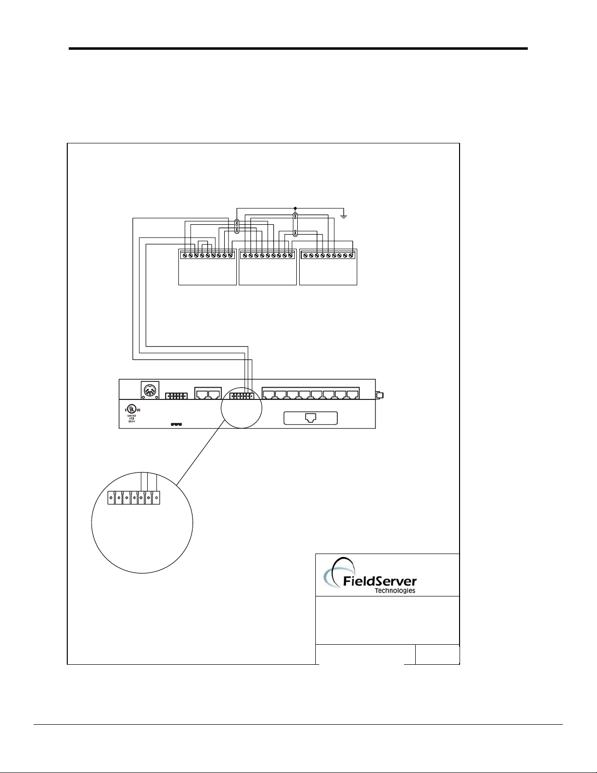
3 Hardware Connections
The FieldServer is connected to the OPTO22 device as shown below.
Configure the OPTO22 device according to manufacturer’s instructions.
FS-X40
GndFG_
+
R2 R1
RS 485
(Opt o - Isolat ed)
B1 OR B2
Net 1
Et he rn et
10 Base T
COM
- + - + - + - +
FO FH TH TO
GndFG_
+
R2 R1
RS 48 5
(Opto - Isolated)
Gnd_+
- + - + - + - +
FO FH TH TO * *
PREVIOUS OPTOMUX *
* B2 COMMUNICATION CONNECTIONS ARE MADE TO THE RACK (PB4AH, PA8AH OR
PB16AH), NOT TO THE BRAIN BOARD.
** DO NOT CONNECT ANY "COM" POINT TO EARTH GROUND.
_
_
+
+12V 500m
Power
+
12V 500m
Net 2
5V 500m
5V 1.5A
0V
FG
DC AUX Power
Gnd
_
COM
- + - + - + - +
FO FH TH TO
GRO U ND 5
DTR 6
RTS 7
Tx 8
NEXT OPTOMUX *
B1 OR B2
RS 23 2
1 Rx
18
2 CTS
3 DSR
4 GROUND
AC30A/B
P8 P7 P 6 P5 P4 P3 P2 P1
COM
(408)-262-2299
FIELDSERVER - OPTO22
CONNECTION DIAGRAM
BASE NAME:
FILE NAME: T28700-17.VSD
DATE: 6/27/01
BY: MN
FieldServer Technologies 1991 Tarob Court, Milpitas, California 95035 (408) 262-22 99 fax: (408) 262-9042
Visit our website: www.fieldserver.com E-mail: support@fieldserver.com
Page 3
Page 6

FS-8700-17 Optomux Driver Manual
4 Configuring the FieldServer as a Optomux Driver Client
For a detailed discussion on FieldServer configuration, please refer to the FieldServer
Configuration Manual. The information that follows describes how to expand upon the
factory defaults provided in the configuration files included with the FieldServer (See “.csv”
files on the driver diskette).
This section documents and describes the parameters necessary for configuring the
FieldServer to communicate with an Optomux Device.
The configuration file tells the FieldServer about its interfaces, and the routing of data
required. In order to enable the FieldServer for Optomux Driver communications, the driver
independent FieldServer buffers need to be declared in the “Data Arrays” section, the
destination device addresses need to be declared in the “Client Side Nodes” section, and
the data required from the servers needs to be mapped in the “Client Side Map
Descriptors” section. Details on how to do this can be found below.
Note that in the tables, * indicates an optional parameter, with the bold legal value being
the default.
4.1 Data Arrays
Section Title
Data_Arrays
Column Title Function Legal Values
Data_Array_Name Provide name for Data Array Up to 15 alphanumeric
Data_Format Provide data format. Each data array can
Data_Array_Length Number of Data Objects. Must be larger
Example
// Data Arrays
//
Data_Arrays
Data_Array_Name, Data_Format, Data_Array_Length
DA_AI_01, UInt16, 200
DA_AO_01, UInt16, 200
DA_DI_01, Bit, 200
DA_DO_01, Bit, 200
characters
FLOAT, BIT, UInt16, SInt16,
only take on one format.
than the data storage area required for
the data being placed in this array.
Packed_Bit, Byte,
Packed_Byte,
Swapped_Byte
1-10,000
FieldServer Technologies 1991 Tarob Court, Milpitas, California 95035 (408) 262-22 99 fax: (408) 262-9042
Visit our website: www.fieldserver.com E-mail: support@fieldserver.com
Page 4
Page 7

FS-8700-17 Optomux Driver Manual
4.2 Client Side Connections
Section Title
Connections
Column Title Function Legal Values
Port Specify which port the device is
connected to the FieldServer
Baud* Specify baud rate
Parity* Specify parity Even, Odd, None, Mark, Space
Data_Bits* Specify data bits 7, 8
Stop_Bits* Specify stop bits
Protocol Specify protocol used Optomux
Handshaking* Specify hardware handshaking RTS, RTS/CTS, None
Poll Delay* Time between internal polls 0-32000 seconds
Example
// Client Side Connections
Connections
Port, Baud, Parity, Protocol, Handshaking, Poll_Delay
R1, 9600, None, Opto22 , None , 0.100s
R1-R2, (FS-X40 Series)
R1 (FS-X20 Series)
110 – 115200, standard baud
rates only
At the time of publication of this
manual the OPTO22 device’s
support standard baud Rates in
the range 300-38400.
1
default 1 second
4.3 Client Side Nodes
Section Title
Nodes
Column Title Function Legal Values
Node_Name Provide name for node Up to 32 alphanumeric
characters
Node_ID OPTO22 device address. 0-255
Protocol Specify protocol used Optomux
Port Specify which port the device is
connected to the FieldServer
Example
// Client Side Nodes
Nodes
Node_Name, Node_ID, Protocol, Port
Optomux1 , 1 , Optomux , R1
FieldServer Technologies 1991 Tarob Court, Milpitas, California 95035 (408) 262-22 99 fax: (408) 262-9042
Visit our website: www.fieldserver.com E-mail: support@fieldserver.com
Page 5
R1-R2, (P1-P8 with a
converter)
Page 8

FS-8700-17 Optomux Driver Manual
4.4 Client Side Map Descriptors
4.4.1 FieldServer Related Map Descriptor Parameters
Column Title Function Legal Values
Map_Descriptor_Name Name of this Map Descriptor Up to 32 alphanumeric
characters
Data_Array_Name Name of Data Array where data is to be
stored / retrieved in the FieldServer.
The use of this array is dependent on
the Optomux command used in the map
descriptor.
For example some commands use one
data value for all module positions to be
affected by the command (Driver will
only use one data array element). Other
commands may use one data element
per module position specified. In this
case the FieldServer may use up to 16
data array elements.
To fully understand this, read the notes
in chapter 6.
Da_Bit_Name* This parameter is only required for
dynamic module position specification.
Ie. You intend using a data array to tell
the driver which module positions to
affect by a command. In this case use
this parameter. Up to 16 elements will
be inspected. The first element will
always be used for the first module
position , the 2
nd
element for the 2nd
module position ….
Module positions are specified by setting
the corresponding array element to a
non-zero value. Module positions are left
unspecified by setting the module array
position to zero.
The first element of this array that is
used is determined by the
Data_Array_Offset parameter.
Additional information is provided in
chapter 6.
One of the Data Array names
from “Data Array” section above
One of the Data Array names
from “Data Array” section above
FieldServer Technologies 1991 Tarob Court, Milpitas, California 95035 (408) 262-22 99 fax: (408) 262-9042
Visit our website: www.fieldserver.com E-mail: support@fieldserver.com
Page 6
Page 9

FS-8700-17 Optomux Driver Manual
Da_Byte_Name* Names a data array that the driver will
use to store poll/query response status
One of the Data Array names
from “Data Array” section above
data.
One data element is used per map
descriptor. The element is determined
by the Data_Array_Offset parameter.
Data_Array_Offset Starting location in Data Array 0 to maximum specified in “Data
Array” section above
Function Function of Client Map Descriptor RDBC, WRBC, WRBX
4.4.2 Driver Related Map Descriptor Parameters
Column Title Function Legal Values
Node_Name Name of Node to fetch data
from
Address* This field is only required if the
address/length method of
module position specification is
used.
Length Length of Map Descriptor
Only some commands / queries
use the value of this map
descriptor parameter. This is
indicated in a table provide in
chapter 6.
For those commands and
queries that do use the Length
parameter the driver never uses
more than 16 elements of data
even if the length is set to a
larger number.
Although this driver does not
use the length parameter for
some commands the
FieldServer kernel does use
this parameter to ensure that no
more than one client map
descriptor has control of a
range of array data elements.
For this reason it is best to
always specify the length – in
these cases set it to 1.
One of the node names
specified in “Client Node
Descriptor” above
1..16
Indicating 1
st
to 16th module
position.
1 - 1000
FieldServer Technologies 1991 Tarob Court, Milpitas, California 95035 (408) 262-22 99 fax: (408) 262-9042
Visit our website: www.fieldserver.com E-mail: support@fieldserver.com
Page 7
Page 10

FS-8700-17 Optomux Driver Manual
Opto22_trigger* An optional parameter. If used then set the
No, Yes
value of this parameter to yes or no and
the da_byte_name parameter must be
specified too.
When this parameter is set to yes then the
Optomux driver processes this map
descriptor differently from a normal wrbc or
rdbc function.
The driver processes the map descriptor at
the scan interval specified. Each time that
it is processed the driver checks the
element of the da_byte_name data array
specified. If the value of the 1
st
element of
array located at data_array_offset is 1 then
the driver executes the command. If the
value is not equal to one then the driver
ignores the map descriptor.
If the map descriptor is triggered then the
driver will write a response status to the
same data element on completion of the
poll. Thus the value of 1 will be set to zero
for success or some other value indicating
an error.
More information is provided in chapter 6.
Opto22_format* This parameter only has meaning when
the function is a read of digital data.
Bit, Packed
By default the OPTO22 devices returns 16
position states when digital data is read (
eg. READ STATUS). The Optomux driver
writes the data as one 16 bit unsigned
integer to one data element of the data
array specified. (That is, the data is written
to the data array in packed bit format.)
For example, if the 1
st
and 5th inputs were
on and all others were off the driver would
write the value 17 to the first element of the
data array.
The driver can be instructed to unpack this
data into separate bit states, writing each
module position’s state to a consecutive
data array element.
When the Bit keyword is used the driver
sets the states of consecutive data array
elements starting at Data_Array_Offset.
The number of elements that are written is
determined by length and a maximum of
16 elements will be written.
Opto22_function This parameter is specified by using one of See Table 6.1
FieldServer Technologies 1991 Tarob Court, Milpitas, California 95035 (408) 262-22 99 fax: (408) 262-9042
Visit our website: www.fieldserver.com E-mail: support@fieldserver.com
Page 8
Page 11

FS-8700-17 Optomux Driver Manual
the functions provided in table 6.1.
The parameter must be spelled and
spaced exactly as provided in the table.
Leading and trailing spaces are not
important but inter-word spaces are very
important. Take care not to use tabs.
Opto22_modifier1* A few Opto22_Functions require one ore
See Chapter 6.
more additional arguments.
SET TIME DELAY
GENERATE N PULSES
READ AND AVERAGE INPUTS
Additional information in chapter 6 will
indicate the types of values that may be
assigned to this parameter.
Opto22_modifier2* See Opto_modifier1
Opto22_mask* The mask specifies the positions (1-16) of
a module that will be affected by a
command.
The positions can be specified dynamically
0-65535
or
0x0000 – 0xffff
using a data array or statically by using this
parameter.
When this parameter is used and its value
is non zero then the driver does not
consider the data contained in the position
defining array even if it is also defined.
The value of the mask may be specified in
hexadecimal or in decimal.
To specify a number in hexadecimal the
number must be prefixed with 0x and have
a maximum of 4 digits.
Examples.
Decimal: 257 -> Indicates the 1
st
and 9th
positions.
Hexadecimal: 0x0101 -> indicates the 1
th
and 9
positions.
st
4.4.3 Timing Parameters
Column Title Function Legal Values
Scan_Interval Rate at which data is polled >0.1s
FieldServer Technologies 1991 Tarob Court, Milpitas, California 95035 (408) 262-22 99 fax: (408) 262-9042
Visit our website: www.fieldserver.com E-mail: support@fieldserver.com
Page 9
Page 12
FS-8700-17 Optomux Driver Manual
4.4.4 Map Descriptor Example 1 – Read on/off Status
In this example the on/off status of all module positions of the Optomux device are read and stored. They are read continuously (rdbc) every 5 seconds
(Scan_Interval). The Read Status command returns one packed 16 bit value. There is one bit per module position, thus, if the returned value was 2 then this would
indicate that the 2nd position is on and all other positions are off.
Map_Descriptor_Name, Data_Array_Name, Data_Array_Offset, Function, node_name, Length, Scan_Interval, opto22_function ,
DEVICE77_STAT , DISC_INPUTS , 0 , rdbc , DEV77 , 1 , 5.0s , READ STATUS ,
Map descriptor
names are often
used in error
messages so it may
be helpful to have
unique names.
Dashes, spaces,
upper and lowercase
characters may be
used.
This is the name of
the data array in
which the data will
be stored.
Ensure that the
Data_Format of the
array is suitable for
storing the data
returned by the
device.
Chapter 6 provides
details of the type of
data returned by
each command.
The device will
be read
continuously.
The data will be
stored at offset
zero (First
element) of the
data array.
This is the name
of the node. The
node must have
previously been
defined in the
Nodes section
of the CSV file.
Its Node_ID
should be set to
77 to reference
the device
addressed as 77.
Only one
element of the
data array is
reserved for this
map descriptor.
This is the name
of the Optomux
command /
query that must
be performed.
It must be
spelled and
spaced exactly
as in table 6.1
FieldServer Technologies 1991 Tarob Court, Milpitas, California 95035 (408) 262-22 99 fax: (408) 262-9042
Visit our website: www.fieldserver.com E-mail: support@fieldserver.com
Page 10
Page 13

FS-8700-17 Optomux Driver Manual
4.4.5 Map Descriptor Example 2 – Read On/Off Status (Data stored differently)
This example reads the same data as the previous example. The difference is that the data is stored differently. In this example the data is
unpacked and stored in 16 consecutive data array elements – one element per m odule position.
Map_Descriptor_Name, Data_Array_Name, Data_Array_Offset, Function, node_name, Length, Scan_Interval, opto22_function , opto22_format
DEVICE77_STAT , DISC_INPUTS , 0 , rdbc , DEV77 , 16 , 5.0s , READ STATUS , Bit
This is how the
driver is instructed
The length has
changed to 16 to
reserve 16 data array
elements for this
map descriptor.
to unpack the digital
data.
FieldServer Technologies 1991 Tarob Court, Milpitas, California 95035 (408) 262-22 99 fax: (408) 262-9042
Visit our website: www.fieldserver.com E-mail: support@fieldserver.com
Page 11
Page 14

FS-8700-17 Optomux Driver Manual
4.4.6 Map Descriptor Example 3 – Command Response/Completion Status
We use example 1 to show how it can be modified to get the driver to expose the response / status generated whe n the command was executed.
The response / status values indicate the success / failure of the command based either on the driver’s ability to complete the command OR on
the ack/nack returned by the device.
Map_Descriptor_Name, Data_Array_Name, Data_Array_Offset, Function, node_name, Length, Scan_Interval, opto22_function , DA_Byte_Name
DEVICE77_STAT , DISC_INPUTS , 0 , rdbc , DEV77 , 1 , 5.0s , READ STATUS, RESPONSE_ARR
By virtue of defining the DA_Byte_Name parameter the
driver will now store a response status each time the poll is
executed.
The response / status code will be stored in the data array
called REPONSE_ARR. One element of the array located
at Data_Array_Offset will be used. The data array’s data
format should at least be able to store a byte of data as
response/status codes range from 0-255.
FieldServer Technologies 1991 Tarob Court, Milpitas, California 95035 (408) 262-22 99 fax: (408) 262-9042
Visit our website: www.fieldserver.com E-mail: support@fieldserver.com
Page 12
Page 15

FS-8700-17 Optomux Driver Manual
4.4.7 Map Descriptor Example 4 – Triggered Action
This example shows the elements necessary to generate a triggered poll. Even though this map descriptor appears to write to the device
continuously the driver recognizes the opto22_trigge r parameter and based on its value will only send the poll when the trigger value is set.
Map_Descriptor_Name, Data_Array_Name, Data_Array_Offset, Function, Node_Name, Length, Scan_Interval, opto22_function , opto22_trigger, DA_Byte_Name
DEVICE77_STAT , CNTR_POSNS , 0 , wrbc , DEV77 , 16 , 0.2s , CLEAR COUNTERS , Yes , COMMAND_ARRAY
This map descriptor
is processed as a
write command and
will be processed
continuously.
The Driver will process this
map descriptor every 0.2
seconds.
In this example, this does not
mean that the command will
be sent to the device every
0.2 seconds. It does mean
that the driver will check to
see if a trigger has been set
every 0.2 seconds.
This keyword value for the
opto22_trigger parameter
tells the driver only to send
this Optomux command if it
has been triggered.
When this parameter is used
the DA_Byte_Name
parameter must also be used.
This is the name of a data array
whose contents will be used to
trigger the command.
The driver looks at the element
found at the Data_Array_Offset
and if that value=1 then the
command is sent. On
completion/error the driver will
change this value to some other
number.
FieldServer Technologies 1991 Tarob Court, Milpitas, California 95035 (408) 262-22 99 fax: (408) 262-9042
Visit our website: www.fieldserver.com E-mail: support@fieldserver.com
Page 13
Page 16

FS-8700-17 Optomux Driver Manual
4.4.8 Map Descriptor Example 5 – Using Address and Length to tell the FieldServer which module positions to access.
This example shows a map descriptor which reads analog inputs from an Optomux Device. The address and length tell the driver which inputs to
read. Take care to ensure that the data array used for storage has a data format suitable for storing the data type returned by the command. In
this case an unsigned integer at least 16 bits long ( eg UINT16 or FLOAT). Also take care to ensure that you understand the scaling of the data
returned by the Optomux device. There are parameters that you can add to a map descripto r to have the d river scale the value. This is discussed
in the FieldServer Configuration Manual.
Map_Descriptor_Name, Data_Array_Name, Data_Array_Offset, Function, Node_Name, Address, Length, Scan_Interval, opto22_function
DEVICE77_STAT , ANA_DATA , 0 , rdbc , DEV77 , 2 , 15 , 1.0s , READ ANALOG INPUTS
Data read from the
Optomux Device is
placed in this array.
Starting at this array
position.
The first module
position that is read
is position 2.
Module positions
are numbered 1 to
16.
Data from 15
module positions
must be read. Thus
starting at 2, the last
module position
read is 16.
This is the Optomux
Driver function that
must be performed.
FieldServer Technologies 1991 Tarob Court, Milpitas, California 95035 (408) 262-22 99 fax: (408) 262-9042
Visit our website: www.fieldserver.com E-mail: support@fieldserver.com
Page 14
Page 17

FS-8700-17 Optomux Driver Manual
4.4.9 Map Descriptor Example 6 – Using a Mask to Address specific module positions
There may be occasions when it is not suitable to use address and length. For example if you are attempting to address non-consecutive
Optomux module positions OR when you wish to use a command that affects all module positions. The driver provides an alternate method for
module position specification by allowing you to specify a mask as a parameter in the CSV file. The mask may be specified in decimal or
hexadecimal format.
In this example, module positions 1 and 5 are pulsed.
Map_Descriptor_Name, Data_Array_Name, Data_Array_Offset, Function, Node_Name, Length, Scan_Interval, opto22_mask, opto22_function
PULSE77 , TIME_DATA , 0 , wrbc , DEV77 , 1 , 10.0s , 0x0011 , START ON PULSE
This function turned
on the specified
Module positions are specified in hexadecimal
in this example.
0x0001 = Module Position 1
0x0002 = Module Position 2
0x0003 = Module Positions 1 & 2
…..
module positions for
a specified period.
Un specified
positions (mask bit
positions equal zero)
are non affected by
the command.
FieldServer Technologies 1991 Tarob Court, Milpitas, California 95035 (408) 262-22 99 fax: (408) 262-9042
Visit our website: www.fieldserver.com E-mail: support@fieldserver.com
Page 15
Page 18
FS-8700-17 Optomux Driver Manual
4.4.10 Map Descriptor Example 7 – Specifying Module Positions Dynamically
Previous examples addressed module positions statically. This example illustrates how you can use a data array’s value to specify the module position’s to be
affected by a command. As data arrays can have their values chan ged by remote devices, the module position specification may be changed dynamically. The
CSV file does not require editing. This method can be used all the time or only if you wish to use one of those commands which would typically require dynamic
addressing.
In this example, module positions 1 and 5 are pulsed.
Map_Descriptor_Name, Data_Array_Name, Data_Array_Offset, Function, Node_Name, Length, Scan_Interval, DA_Bit_Name , opto22_function
CLRLOW77 , LOW_ARRAY , 0 , wrbc , DEV77 , 16 , 10.0s , POS_ARR , READ AND CLEAR LOWEST VALUES
In this example, the driver will store 16 lowest values in an array
called LOW_ARR starting at position Data_Array_Offset.
Any number 1 to 16.
The driver stops at
16, ignoring larger
values.
This data array will be used by
the driver to determine the
module positions to be affected
by the command.
The driver uses the length
(max=16) and the
Data_Array_Offset. The first
specified element corresponds to
module position 1. If its value is
non-zero then the position is
specified by the driver.
FieldServer Technologies 1991 Tarob Court, Milpitas, California 95035 (408) 262-22 99 fax: (408) 262-9042
Visit our website: www.fieldserver.com E-mail: support@fieldserver.com
Page 16
Page 19

5 Configuring the FieldServer as a Optomux Server
The FieldServer does not support the emulation of an Optomux server at present.
FieldServer Technologies 1991 Tarob Court, Milpitas, California 95035 (408) 262-2299 fax: (408) 262-9042
Visit our website: www.fieldserver.com E-mail: support@fieldserver.com
Page 17
Page 20

FS-8700-17 Optomux Driver Manual
6 Driver Notes
6.1 Data_Array_Name, DA_Bit_Name, DA_Byte_Name
These parameters are used to specify data array names. Despite their
names a data array of any Data_Format can be used for any of these
parameters.
This driver uses DA_Byte_Name exclusively as a location for the commands
to trigger map descriptors and in which to store poll response status.
The use of DA_Bit_Name is command sensitive and is used to allow the
values in a data array to determine the module positions to be affected by a
command.
The use of the Data_Array_Name Parameter is typical i.e. Used to store
data that is read or used as a source for data that is written.
6.2 Module Positions
Specify module positions Statically by
• Using Address and Length or
• Using the opto22_mask parameter or
Specify module positions dynamically by
• Using the values of a data array (da_bit_array)
What happens if more than one method is used for module position specification ?
The driver evaluates the specification in the order listed above. Thus if address &
length are specified as well as the opto22_mask, the driver will use the address
and length.
6.3 Command Response Status
If a data array is specified using the DA_Byte_Array parameter then the driver
will store a response status code in the array, updating the value each time a
command is executed.
Value Description
0 Command completed successfully.
1 Used to trigger a command.
All other values indicate error conditions. For Responses 128 to
FieldServer Technologies 1991 Tarob Court, Milpitas, California 95035 (408) 262-2299 fax: (408) 262-9042
Visit our website: www.fieldserver.com E-mail: support@fieldserver.com
Page 18
Page 21

FS-8700-17 Optomux Driver Manual
255 the Optomux literature should be read for additional
information as these are codes returned by the Optomux device.
128 Nak from Optomux Device. Power Up Clear Expected. Command
Ignored.
129 Nak from Optomux Device. Undefined Command
130 Nak from Optomux Device. Checksum Error
131 Nak from Optomux Device. Input Buffer Overun
132 Nak from Optomux Device. Non Printable Ascii character received
133 Nak from Optomux Device. Data Field Error
134 Nak from Optomux Device. Communication watchdog timeout
135 Nak from Optomux Device. Specified limits invalid.
The following codes are generated by the driver. They all indicate
errors.
250 An ack with no data was expected. Ack with Data was received.
251 The driver Complete function returned an error, could be
checksum, bad 1st char ... ie. The message was badly formatted.
252 Driver Timeout
253 An ack was received but it was badly formatted
254 A nak was received but was badly formatted
255 Message was not acknowledged correctly.
6.4 Optomux Commands
The following provides a list of commands supported by the driver. The Command
Name’s provided in the table must be used in providing values for the opto22_function
parameter. The notes provided only apply when module positions are specified
dynamically.
FieldServer Technologies 1991 Tarob Court, Milpitas, California 95035 (408) 262-2299 fax: (408) 262-9042
Visit our website: www.fieldserver.com E-mail: support@fieldserver.com
Page 19
Page 22

FS-8700-17 Optomux Driver Manual
Read/
Write/
Both
w
w
w
w
w
w
r
w
w
w
w
w
w
w
r
w
w
w
r
w
COMMAND NAME OPTO22_FORMAT
OPTION
POWER UP CLEAR 4
RESET 4
SET TURN-AROUND DELAY 4
SET WATCHDOG DELAY 4
SET WATCHDOG DELAY (Analog) 3
SET PROTOCOL 4
IDENTIFY Optomux TYPE 4
SET ENHANCED DIGITAL WATCHDOG 3
SET ENHANCED ANALOG WATCHDOG 1
SET TIMER RESOLUTION
SET TEMPERATURE PROBE TYPE 3
CONFIGURE POSITIONS 3
CONFIGURE AS INPUTS 3
CONFIGURE AS OUTPUTS 3
READ MODULE CONFIGURATION 4
WRITE OUTPUTS 1
ACTIVATE OUTPUTS 3
DEACTIVATE OUTPUTS 3
READ STATUS 1 2
SET LATCH EDGES 3
MASTER LENGTH
CONSIDERED (See
Notes)
Uses 1 element of data array. Legal
values are 0,1,2,3
Uses 1 element of data array. Legal
values are 0 to 7
Uses the 1st element of data array for
the timer value.
Uses 1 element of data array. Legal
values are 0,1
Polled data is stored in the 1st
element of the data array.
Delay is found in data array.
Uses up to Length (max=16) array
elements. Module positions specified
get setup for fail values by using the
corresponding positions in data array.
Uses 1 element of data array.
Temp probe type is found in first
element of data array
Non-zero module positions get set to
outputs. Zero module positions get
set to inputs
Only module positions specified get
affected by command.
Only module positions specified get
affected by command.
Uses up to Length (max=16) array
elements. Non-zero elements get
turned on, zero value elements get
turned off.
Only module positions specified get
affected by command.
Only module positions specified get
affected by command.
If format=Bit then length is considered
during storage as bits are unpacked
into data array. If format is non equal
to bit then result is written as a single
value into one array element.
Retrieved data is stored in data array.
Always affects all module positions.
Cannot be limited by length. Length is
only used when determining which
module positions are specified as
non-zero. Non-zero (Specified)
elements get set on->off, Zero (Non-
NOTES
FieldServer Technologies 1991 Tarob Court, Milpitas, California 95035 (408) 262-2299 fax: (408) 262-9042
Visit our website: www.fieldserver.com E-mail: support@fieldserver.com
Page 20
Page 23

FS-8700-17 Optomux Driver Manual
Read/
Write/
Both
w
w
r
b
w
w
w
w
r
b
w
w
w
w
w
w
COMMAND NAME OPTO22_FORMAT
OPTION
SET LATCH OFF TO ON 3
SET LATCH ON TO OFF 3
READ LATCHES 1 2
READ AND CLEAR LATCHES 1 3,2
CLEAR LATCHES 3
START/STOP COUNTERS 3
START COUNTERS 3
STOP COUNTERS 3
READ COUNTERS 1
READ AND CLEAR COUNTERS 1
CLEAR COUNTERS 3
SET TIME DELAY 3
INITIATE SQUARE WAVE 3
HIGH RESOLUTION SQUARE WAVE 3
RETRIGGER TIME DELAY 3
GENERATE N PULSES 3
MASTER LENGTH
CONSIDERED (See
Notes)
NOTES
Specified) module positions get set
off->on
Only module positions specified get
affected by command.
Only module positions specified get
affected by command.
If format=Bit then length is considered
during storage as bits are unpacked
into data array. If format is non equal
to bit then result is written as a single
value into one array element.
Non-zero (Specified) module
positions get affected (cleared) by
command. But all positions get read.
Read data get stored in data array.
During storage opto22_format is
considered. If format=bit then data is
unpacked and stored otherwise the
result for all 16 positions is stored as
one data element.
Only module positions specified get
affected by command.
All positions are affected by
command. Non-zero (specified)
module positions start counting, zero
(unspecified) module positions stop
counting
Only module positions specified get
affected by command.
Only module positions specified get
affected by command.
Data that is read is put into the
corresponding array elements of the
data array based on which module
positions are read.
Data that is read is put into the
corresponding array elements of the
data array based on which module
positions are read.
Only module positions specified get
affected by command.
The Modifier is specified in the CSV
file with the opto22_modifier1
parameter. The data (timeout) is
retrieved from the first element of the
data array.
Only module positions specified get
affected by command.
Only specified module positions get
FieldServer Technologies 1991 Tarob Court, Milpitas, California 95035 (408) 262-2299 fax: (408) 262-9042
Visit our website: www.fieldserver.com E-mail: support@fieldserver.com
Page 21
Page 24

FS-8700-17 Optomux Driver Manual
Read/
Write/
Both
w
w
w
w
w
r
r
b
w
w
r
w
r
COMMAND NAME OPTO22_FORMAT
START ON PULSE 3
START OFF PULSE 3
SET TRIGGER POLARITY 3
TRIGGER ON POSITIVE 3
TRIGGER ON NEGATIVE 3
READ PULSE COMPLETE BITS 1 2
READ DURATION COUNTERS 3
READ AND CLEAR DURATION
COUNTERS
CLEAR DURATION COUNTERS 3
WRITE ANALOG OUTPUTS 3
READ ANALOG OUTPUTS 3
UPDATE ANALOG OUTPUTS 3
READ ANALOG INPUTS 3
OPTION
3
MASTER LENGTH
CONSIDERED (See
Notes)
NOTES
affected. The Modifier (byte 1&2) are
specified in the CSV file with the
opto22_modifier1/2 parameters. The
data (number of pulses) is retrieved
from the 1st element of the data
array.
Only specified module positions get
affected. The data (period of pulses)
is retrieved from the 1st element of
the data array.
Only specified module positions get
affected. The data (period of pulses)
is retrieved from the first element of
the data array.
All Module positions are affected by
this command. Non-zero (Specified)
module positions triggered by on,
zero module positions (un-specified)
elements get triggered by off.
Only module positions specified get
affected by command.
Only module positions specified get
affected by command.
If format=Bit then length is considered
during storage as bits are unpacked
into data array. If format is non equal
to bit then result is written as a single
value into one array element.
Retrieved data is stored in standard
data array.
Only specified module positions get
read. Data read gets put in
corresponding positions of data array.
Only specified module positions get
read. Data read gets put in
corresponding positions of data array.
Only module positions specified get
affected by command.
Only specified module positions get
written. Data written gets extracted
from corresponding positions of data
array.
Only specified module positions get
read. Data read gets put in
corresponding positions of data array.
Only specified module positions get
written. Data written gets extracted
from corresponding positions of data
array.
Only specified module positions get
read. Data read gets put in
corresponding positions of data array.
FieldServer Technologies 1991 Tarob Court, Milpitas, California 95035 (408) 262-2299 fax: (408) 262-9042
Visit our website: www.fieldserver.com E-mail: support@fieldserver.com
Page 22
Page 25

FS-8700-17 Optomux Driver Manual
Read/
Write/
Both
r
w
r
r
r
r
w
r
b
w
r
w
b
r
w
COMMAND NAME OPTO22_FORMAT
OPTION
READ AND AVERAGE INPUT 4
START INPUT AVERAGING 3
READ AVERAGE COMPLETE BITS 1 2
READ INPUT AVERAGE DATA 3
READ TEMPERATURE INPUTS 3
READ AVERAGE TEMPERATURE INPUTS 3
SET INPUT RANGE 3
READ OUT-OF-RANGE LATCHES 4
READ AND CLEAR RANGE LATCHES 3
CLEAR OUT-OF-RANGE LATCHES 4
READ LOWEST VALUES 3
CLEAR LOWEST VALUES 3
READ AND CLEAR LOWEST VALUES 3
READ PEAK VALUES 3
CLEAR PEAK VALUES 3
MASTER LENGTH
CONSIDERED (See
Notes)
NOTES
Only one module position may be
specified. This position is averaged
and the result is put in the first
element of the data array The number
of samples is specified in modifier1 in
the csv file.
Only specified module positions get
affected by command. First element
in data array is sent as the number of
sample to average over.
If format=Bit then length is considered
during storage as bits are unpacked
into data array. If format is non equal
to bit then result is written as a single
value into one array element.
Retrieved data is stored in standard
data array.
Only specified module positions get
read. Data read gets put in
corresponding positions of data array.
Only specified module positions get
read. Data read gets put in
corresponding positions of data array.
Only specified module positions get
read. Data read gets put in
corresponding positions of data array.
Only specified module positions have
their range set to the 2 values found
in the data array. 1st is high limit,
second is lo limit.
High limit latches are placed in first
element of data array. Low limit
latches are placed in 2nd element of
data array.
Only specified module positions get
read and cleared. Data read gets put
in corresponding positions of data
array.
Only specified module positions get
read. Data read gets put in
corresponding positions of data array.
Only module positions specified get
affected by command.
Only specified module positions get
read and cleared. Data read gets put
in corresponding positions of data
array.
Only specified module positions get
read. Data read gets put in
corresponding positions of data array.
Only module positions specified get
FieldServer Technologies 1991 Tarob Court, Milpitas, California 95035 (408) 262-2299 fax: (408) 262-9042
Visit our website: www.fieldserver.com E-mail: support@fieldserver.com
Page 23
Page 26

FS-8700-17 Optomux Driver Manual
Read/
Write/
Both
b
r
w
r
r
w
r
w
w
COMMAND NAME OPTO22_FORMAT
OPTION
READ AND CLEAR PEAK 3
CALCULATE OFFSETS 1
SET OFFSETS 1
CALCULATE AND SET OFFSETS 1
CALCULATE GAIN COEFFICIENTS 1
SET GAIN COEFFICIENTS 1
CALCULATE AND SET GAIN 1
SET OUTPUT WAVEFORM R 4
IMPROVED OUTPUT WAVEFORMS 4
MASTER LENGTH
CONSIDERED (See
Notes)
Notes on how the Length parameter is used in the CSV file.
1. The length parameter is always considered.
2. The length parameter is only considered when the keyword Bit is used in the
opto22_format parameter.
3. The length is only used using the address/length method to specify module
positions or when the dynamic method is used to specify module positions.
4. The length is never considered.
NOTES
affected by command.
Only specified module positions get
read and cleared. Data read gets put
in corresponding positions of data
array.
Only specified module positions get
calculated and read. Data read gets
put in corresponding positions of data
array.
Only specified module positions get
written. Data written gets extracted
from corresponding positions of data
array.
Only specified module positions get
calculated and read. Data read gets
put in corresponding positions of data
array.
Only specified module positions get
calculated and read. Data read gets
put in corresponding positions of data
array.
Only specified module positions get
written. Data written gets extracted
from corresponding positions of data
array.
Only specified module positions get
calculated and read. Data read gets
put in corresponding positions of data
array.
Uses opto22_modifier1/2 from the
CSV file set waveform rates and
types. Only specified positions get
affected. 2 elements of data array
are used.
Uses opto22_modifier1/2 from the
CSV file set waveform rates and
types. Only specified positions get
affected. 3 elements of data array
are used.
FieldServer Technologies 1991 Tarob Court, Milpitas, California 95035 (408) 262-2299 fax: (408) 262-9042
Visit our website: www.fieldserver.com E-mail: support@fieldserver.com
Page 24
Page 27

FS-8700-17 Optomux Driver Manual
6.5 Driver Stats
In addition to the standard FieldServer communication statistics described in the FieldServer
User’s Manual the Optomux Driver can also
a data array. A special map descriptor is required. The driver recognizes the map
descriptor by its name which must be "opto22-stats" .
The following example shows how this special map descriptor can be configured.
Nodes
Node_name, Node_ID, Protocol
null_node, 0 , Optomux
Data_Arrays
Data_Array_Name, Data_Format, Data_Array_Length
OPTO22_STATS , UINT32 , 300
Map_Descriptors
Map_descriptor_Name, Data_Array_Name, Node_name, length
Opto22-stats , OPTO22_STATS , null_node , 300
When the driver sees this map descriptor it uses the data array SK_STATS (in this
example) to store driver specific statistics. Only one of these map descriptors may be
specified per FieldServer.
The driver stores the following data.
Array Element Contents
0
1 OPTO_STAT_DYNAMIC_MASK Mask cannot be specified in a
2 OPTO_STAT_TIMEOUT
3 OPTO_STAT_STREAMING
4 OPTO_STAT_NAK
5 OPTO_STAT_PROTOCOL
6 OPTO_STAT_IC_TIMEOUT
7 OPTO_STAT_DEVICE_MSG_RECD
8 OPTO_STAT_DEVICE_BYTES_RECD
9 OPTO_STAT_DEVICE_FUNCTION
10 OPTO_STAT_NO_START
11 OPTO_STAT_MSG_IGNORED
12 OPTO_STAT_POLL_MSG_SENT
12 OPTO_STAT_POLL_BYTES_SENT
expose some driver statistics by writing data to
OPTO_STAT_BAD_FUNCTION
The Opto22_Function has a
bad value.
CSV file with a zero value.
FieldServer Technologies 1991 Tarob Court, Milpitas, California 95035 (408) 262-2299 fax: (408) 262-9042
Visit our website: www.fieldserver.com E-mail: support@fieldserver.com
Page 25
Page 28

FS-8700-17 Optomux Driver Manual
7 Revision History
Date Resp Format Driver Ver.
2/18/04 JD MF 0 1 Releasing
Doc.
Rev.
Comment
FieldServer Technologies 1991 Tarob Court, Milpitas, California 95035 (408) 262-2299 fax: (408) 262-9042
Visit our website: www.fieldserver.com E-mail: support@fieldserver.com
Page 26
 Loading...