

Page 1

Driver Version:
1.01
Document Revision:
2
APPLICABILITY & EFFECTIVITY
Effective for all systems manufactured after November 2009
Driver Manual
(Supplement to the FieldServer Instruction Manual)
FS-8700-17 Opto22
A Sierra Monitor Company
Page 2

FS-8700-17_Opto22.doc Manual Table of Contents
TABLE OF CONTENTS
1 Optomux Driver Description ..................................................................................................................... 1
1.1 Operating Methods ............................................................................................................................................. 1
1.1.1 Static Operation .......................................................................................................................................... 1
1.1.2 Dynamic Operation ..................................................................................................................................... 1
1.1.3 Triggered Operation .................................................................................................................................... 1
1.2 Statistics and Command Reponses..................................................................................................................... 1
2 Driver Scope of Supply ............................................................................................................................. 2
2.1 Supplied by FieldServer Technologies for this driver ........................................................................................ 2
2.2 Provided by Supplier of 3rd Party Equipment .................................................................................................... 2
3 Hardware Connections ............................................................................................................................. 3
3.1 Connection Notes ................................................................................................................................................ 3
4 Data Array Parameters ............................................................................................................................. 4
5 Configuring the FieldServer as an Optomux Driver Client ........................................................................... 5
5.1 Client Side Connection Parameters .................................................................................................................... 5
5.2 Client Side Nodes ................................................................................................................................................. 6
5.3 Client Side Map Descriptors................................................................................................................................ 6
5.3.1 FieldServer Related Map Descriptor Parameters ...................................................................................... 6
5.3.2 Driver Related Map Descriptor Parameters............................................................................................... 7
5.3.3 Timing Parameters ...................................................................................................................................... 8
5.3.4 Map Descriptor Example – Read on/off Status ......................................................................................... 9
Appendix A. Useful Features ........................................................................................................................... 10
Appendix A.1. Module Positions ................................................................................................................................... 10
Appendix A.1.1. Static Specification ...................................................................................................................... 10
Appendix A.1.2. Map Descriptor Example - Static Specification Using a Mask to Address specific module
positions 11
Appendix A.1.3. Map Descriptor Example -Specifying Module Positions Dynamically ...................................... 12
Appendix A.1.4. Map Descriptor Example – Triggered Action ............................................................................ 13
Appendix A.2. Store Unpacked Bit Data ....................................................................................................................... 14
Appendix A.3. Expose Command Response/Completion Status ................................................................................ 14
Appendix B. Reference ................................................................................................................................... 15
Appendix B.1. Optomux Commands............................................................................................................................. 15
Appendix B.2. Command Response Status .................................................................................................................. 21
Appendix B.3. Driver Stats ............................................................................................................................................. 21
FieldServer Technologies 1991 Tarob Court Milpitas, California 95035 USA Web: www.fieldserver.com
Tel: (408) 262 2299 Fax: (408) 262 2269 Toll Free: (888) 509 1970 email: support@fieldserver.com
Page 3

FS-8700-17_Opto22.doc Manual Page 1 of 24
1 OPTOMUX DRIVER DESCR IPTION
The Optomux Driver allows the FieldServer to transfer data to and from devices over either RS-232 or RS-485 using
the Optomux Driver protocol.
The Optomux driver is a client only driver. This means that the driver can poll an Optomux protocol compliant
device but cannot emulate one.
The Optomux protocol provides a large command set. Many of the commands are used for OPTO22 device
configuration. This driver supports the full command set and thus the driver may be used to configure as well as to
poll OPTO22 devices.
1.1 Operating Methods
The Optomux driver provides three methods of operation. Users may use any combination of methods.
1.1. 1 Static Operation
The devices to be polled/commanded are configured using the FieldServer CSV file. If the hardware configuration
is fixed and known then this is a suitable method.
1.1. 2 Dynamic Ope ration
The commands set can be configured by changing the values in the FieldServer’s Data Arrays. This data driven
operating mode is suitable if the hardware configuration may change or if hardware settings may change
dynamically or to change some aspect of the hardware configuration without changing the CSV file and resetting
the FieldServer..
1.1. 3 Triggered Operation
This operating mode allows commands to be triggered by changing the value in the FieldServer’s Data Arrays. This
operating mode is useful if requiring an action triggered by a remote device.
1.2 Statistics and Command Reponses
All FieldServer drivers report communication statistics that allow the operation of the driver to be monitored.
In addition to the standard statistics, this driver exposes the communication statistics for each port by presenting
them in a user specified Data Array where they can be monitored by a remote device or HMI system.
The Optomux driver also exposes the response status to each poll and command (if required) by writing the
response statuses to a user specified Data Array. This useful feature allows remote devices to check whether a
command has been completed successfully.
FieldServer Technologies 1991 Tarob Court Milpitas, California 95035 USA Web: www.fieldserver.com
Tel: (408) 262 2299 Fax: (408) 262 2269 Toll Free: (888) 509 1970 email: support@fieldserver.com
Page 4

FS-8700-17_Opto22.doc Manual Page 2 of 24
FieldServer Technologies PART #
Description
FS-8700-17
Driver Manual.
Part #
Description
Optomux System
2 DRIVER SCOPE OF SUPPLY
2.1 Supplied by FieldSer ver Technologies for this dri ver
2.2 Provided by Supplier of 3
rd
Party Equipment
FieldServer Technologies 1991 Tarob Court Milpitas, California 95035 USA Web: www.fieldserver.com
Tel: (408) 262 2299 Fax: (408) 262 2269 Toll Free: (888) 509 1970 email: support@fieldserver.com
Page 5
FS-8700-17_Opto22.doc Manual Page 3 of 24
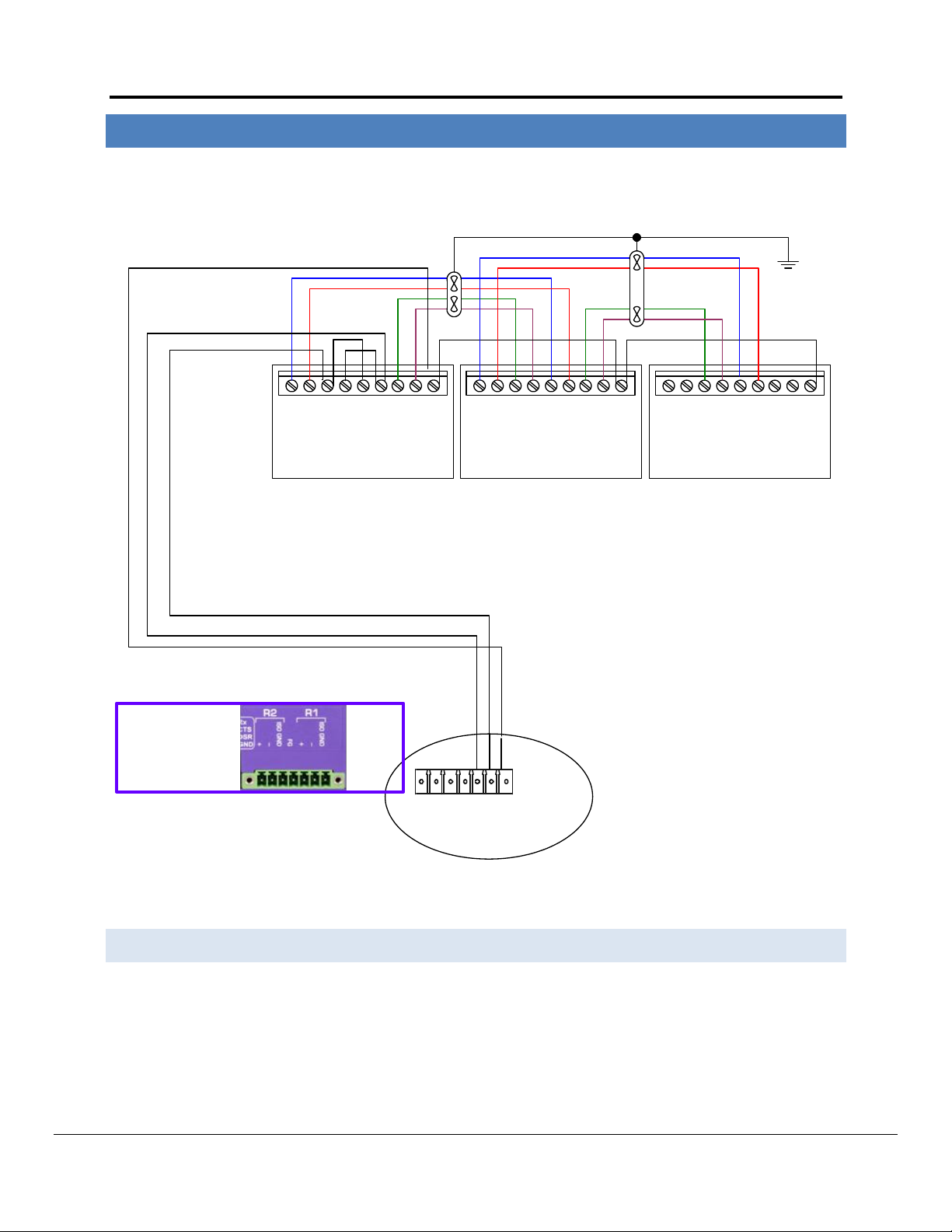
- + - + - + - +
COM
FH TH
PREVIOUS OPTOMUX
- + - + - + - +
COM
AC 30 A/ B
- + - + - + - +
COM
NEXT OPTOMUX
R2 R1
Gnd
_
+
Gnd
FG
_
+
FO TO FH THFO TO
FH THFO TO
FieldServer
B1 or B2
B1 or B2
RS-485
Opto Isolated
3 HARDWARE CONNECTIONS
The FieldServer is connected to the OPTO22 device as shown below.
Configure the OPTO22 device according to manufacturer’s instructions.
3.1 Connection Notes
B2 Communication connections are made to the rack (PB4AH, PA8AH, PB16AH), not to the brain board.
COM points must not be connected to Earth Ground.
Bridging 4-wire RS-422 to get 2-wire RS-485 may not work in certain applications, and in this case it is
recommended that a RS-232 to RS-422 converter is used in between the FieldServer and the OPTO 22 devices .
FieldServer Technologies 1991 Tarob Court Milpitas, California 95035 USA Web: www.fieldserver.com
Tel: (408) 262 2299 Fax: (408) 262 2269 Toll Free: (888) 509 1970 email: support@fieldserver.com
Page 6

FS-8700-17_Opto22.doc Manual Page 4 of 24
Section Title
Data_Arrays
Column Title
Function
Legal Values
Data_Array_Name
Provide name for Data Array
Up to 15 alphanumeric characters
Data_Array_Format
Provide data format. Each Data Array can only take on
one format.
Float, BIT, UInt16, SInt16,
Packed_Bit, Byte, Packed_Byte,
Swapped_Byte
Data_Array_Length
Number of Data Objects. Must be larger than the data
storage area required by the Map Descriptors for the
data being placed in this array.
1-10, 000
// Data Arrays
Data_Arrays
Data_Array_Name
, Data_Array_Format
, Data_Array_Length
DA_AI_01
, UInt16
, 200
DA_AO_01
, UInt16
, 200
DA_DI_01
, Bit
, 200
DA_DO_01
, Bit
, 200
4 DATA ARRAY PARAMETERS
Data Arrays are “protocol neutral” data buffers for storage of data to be passed between protocols. It is necessary
to declare the data format of each of the Data Arrays to facilitate correct storage of the relevant data.
Example
FieldServer Technologies 1991 Tarob Court Milpitas, California 95035 USA Web: www.fieldserver.com
Tel: (408) 262 2299 Fax: (408) 262 2269 Toll Free: (888) 509 1970 email: support@fieldserver.com
Page 7

FS-8700-17_Opto22.doc Manual Page 5 of 24
Section Title
Connections
Column Title
Function
Legal Values
Port
Specify which port the device is
connected to the FieldServer
R1-R2, (FS-X40 Series)
R1 (FS-X20 Series)
Baud*
Specify baud rate
Standard baud Rates in the range 300-38400. (Vendor
Limitation), 9600
Parity*
Specify parity
Even, Odd, None, Mark, Space
Data_Bits*
Specify data bits
7, 8
Stop_Bits*
Specify stop bits
1 (Vendor Limitation)
Protocol
Specify protocol used
Optomux
Poll Delay*
Time between internal polls
0-32000 seconds, 1 second
// Client Side Connections
Connections
Port
, Baud
, Parity
, Protocol
, Poll_Delay
R1
, 9600
, None
,Opto22
, 0.100s
5 CO NFIGURING THE FI ELDSERVER AS AN OPTOMUX DRIVER CLIENT
For a detailed discussion on FieldServer configuration, please refer to the FieldServer Configuration Manual. The
information that follows describes how to expand upon the factory defaults provided in the configuration files
included with the FieldServer (See “.csv” files on the driver diskette).
This section documents and describes the parameters necessary for configuring the FieldServer to communicate
with an Optomux Device.
The configuration file tells the FieldServer about its interfaces, and the routing of data required. In order to enable
the FieldServer for Optomux Driver communications, the driver independent FieldServer buffers need to be
declared in the “Data Arrays” section, the destination device addresses need to be declared in the “Client Side
Nodes” section, and the data required from the servers needs to be mapped in the “Client Side Map Descriptors”
section. Details on how to do this can be found below.
Note that in the tables, * indicates an optional parameter, with the bold legal value being the default.
5.1 Client S ide Connection Parameters
Example
FieldServer Technologies 1991 Tarob Court Milpitas, California 95035 USA Web: www.fieldserver.com
Tel: (408) 262 2299 Fax: (408) 262 2269 Toll Free: (888) 509 1970 email: support@fieldserver.com
Page 8

FS-8700-17_Opto22.doc Manual Page 6 of 24
Section Title
Nodes
Column Title
Function
Legal Values
Node_Name
Provide name for node
Up to 32 alphanumeric characters
Node_ID
OPTO22 device address.
0-255
Protocol
Specify protocol used
Optomux
Port
Specify which port the device is connected to the FieldServer
P1-P8 (with convertor), R1-R21
// Client Side Nodes
Nodes
Node_Name
, Node_ID
, Protocol
, Port
Optomux1
, 1
, Optomux
, R1
Column Title
Function
Legal Values
Map_Descriptor_Name
Name of this Map Descriptor
Up to 32 alphanumeric
characters
Data_Array_Name
Name of Data Array where data is to be stored / retrieved
in the FieldServer.
The use of this array is dependent on the Optomux
command used in the Map Descriptor.
For example some commands use one data value for all
module positions to be affected by the command (Driver
will only use one Data Array element). Other commands
may use one data element per module position specified. In
this case the FieldServer may use up to 16 Data Array
elements.
One of the Data Array
names from Section 4.
Data_Array_Offset
Starting location in Data Array
O to
(Data_Array_Length-1)
Function
Function of Client Map Descriptor
Rdbc, Wrbc, Wrbx
1
5.2 Client S ide Nodes
Example
5.3 Client S ide Map Descriptors
5.3. 1 FieldSer ver Related Map Desc riptor Parameters
Not all ports shown are necessarily supported by the hardware. Consult the appropriate Instruction manual for details of the ports available
on specific hardware.
FieldServer Technologies 1991 Tarob Court Milpitas, California 95035 USA Web: www.fieldserver.com
Tel: (408) 262 2299 Fax: (408) 262 2269 Toll Free: (888) 509 1970 email: support@fieldserver.com
Page 9

FS-8700-17_Opto22.doc Manual Page 7 of 24
Column Title
Function
Legal Values
Node_Name
Name of Node to fetch data from
One of the
Node names
specified in
Section 5.2
Length
Length of Map Descriptor. Commands and queries that use the value of
this Map Descriptor parameter are indicated in Appendix B.1 The driver
uses a maximum of 16 elements of data.
The FieldServer kernel uses this parameter to ensure that no more than
one Client Map Descriptor has control of a range of array data
elements. It is therefore recommended that the parameter is set even
if not required by the command/query.- in these cases set it to 1.
1 - 1000
Opto22_Function
This parameter is specified using one of the functions listed in Appendix
B.1. The parameter must be spelled and spaced exactly as provided in
the table. Leading and trailing spaces are not important but inter-word
spaces are very important. Tabs are not permitted.
See Appendix
B.1
Address*
This field is only required if the address/length method of module
position specification is used. Refer to Appendix A.2
1..16
Opto22_Format*
This parameter only has meaning when the function is a read of digital
data. The parameter instructs the driver to unpack this data into
separate bit states, writing each module position’s state to a
consecutive Data Array element. Refer to Appendix A.2
Bit, Packed
Opto22_Trigger*
An optional parameter used in conjunction with the Da_Byte_Name
parameter. If the parameter is set, a poll will only be sent when the
trigger value is set. More information is provided in Appendix A.1.4.
No, Yes
Opto22_modifier1*
Some Opto22_Functions require one or more additional arguments.
SET TIME DELAY
GENERATE N PULSES
READ AND AVERAGE INPUTS
See Appendix
B.1
Opto22_modifier2*
Opto22_Mask*
This parameter allows the user to statically specify the positions (1-16)
of a module that will be affected by a command. When this parameter
is used and its value is non zero then the driver does not consider the
data contained in the position defining array even if it is also defined.
Refer also to Appendix A.1.1
0-65535
or
0x0000 – 0xffff
Da_Bit_Name*
This parameter is only required for dynamic module position
specification. The Data Array is used to tell the driver which module
positions to affect by a command. Additional information is provided in
Appendix A.1.3
One of the Data
Array names
from Section 4.
Da_Byte_Name*
This driver uses DA_Byte_Name exclusively as a location for the
commands to trigger Map Descriptors and in which to store poll
response status. Refer to Appendix A.1.4
One data element is used per Map Descriptor. The element is
determined by the Data_Array_Offset parameter.
One of the Data
Array names
from Section 4.
5.3. 2 Drive r Related M ap Des criptor P ar ameters
FieldServer Technologies 1991 Tarob Court Milpitas, California 95035 USA Web: www.fieldserver.com
Tel: (408) 262 2299 Fax: (408) 262 2269 Toll Free: (888) 509 1970 email: support@fieldserver.com
Page 10

FS-8700-17_Opto22.doc Manual Page 8 of 24
Column Title
Function
Legal Values
Scan_Interval
Rate at which data is polled
>0.1s
5.3. 3 Timing Parameters
FieldServer Technologies 1991 Tarob Court Milpitas, California 95035 USA Web: www.fieldserver.com
Tel: (408) 262 2299 Fax: (408) 262 2269 Toll Free: (888) 509 1970 email: support@fieldserver.com
Page 11

FS-8700-17_Opto22.doc Manual Page 9 of 24
Map_Descriptor_Name
, Data_Array_Name
, Data_Array_Offset
, Function
, Node_Name
, Length
, Scan_Interval
, Opto22_Function
DEVICE77_STAT
, DISC_INPUTS
, 0
, Rdbc
, DEV77
, 1
, 5.0s
, READ STATUS
This is the name of the
Optomux command /
query that must be
performed.
It must be spelled and
spaced exactly as in
Appendix B.1
Only one
element of the
data array is
reserved for
this Map
Descriptor.
The data will be
stored at offset
zero (First
element) of the
data array.
The device will
be read
continuously.
Map Descriptor
names are often
used in error
messages so it is
usefull to have
unique names.
Dashes, spaces,
upper and
lowercase
characters may be
used.
The data array in
which the data will
be stored.
Ensure that the
Data Format of the
array is suitable for
storing the data
returned by the
device. Appendix
B.1 provides details
of the type of data
returned by each
command.
The node must
have previously
been defined in
the Nodes
section of the
CSV file. Its
Node_ID should
be set to 77 to
reference the
device
addressed as
77.
5.3. 4 Map Descriptor Example – Read on/off Status
In this example the on/off status of all module positions of the Optomux device are read and stored. They are read continuously (Rdbc) every 5 seconds
(Scan_Interval). The Read Status command returns one packed 16 bit value. There is one bit per module position, thus, if the returned value was 2 then this
would indicate that the 2nd position is on and all other positions are off.
FieldServer Technologies 1991 Tarob Court Milpitas, California 95035 USA Web: www.fieldserver.com
Tel: (408) 262 2299 Fax: (408) 262 2269 Toll Free: (888) 509 1970 email: support@fieldserver.com
Page 12

FS-8700-17_Opto22.doc Manual Page 10 of 24
Map_Descriptor_Name
, Data_Array_Name
, Data_Array_Offset
, Function
, Node_Name
, Address
, Length
, Scan_Interval
, Opto22_function
DEVICE77_STAT
, ANA_DATA
, 0
, Rdbc
, DEV77
, 2
, 15
, 1.0s
, READ ANALOG INPUTS
Data read from the
Optomux Device is
placed in this array.
Starting at this
array position.
The first module position
that is read is position 2.
Module positions are
numbered 1 to 16.
Data from 15 module
positions must be read.
Thus starting at 2, the last
module position read is 16.
This is the Optomux
Driver function that
must be performed.
Appendix A. Useful Features
Appendix A.1. Module Positions
Appendix A.1.1. St at ic Specifi cat ion
Specify module positions statically by
Using Address and Length
Using the Opto22_Mask parameter
If more than one method is used for module position specification, the driver evaluates the specification in the order listed above. Thus if address & length are
specified as well as the opto22_mask, the driver will use the address and length.
Take care to ensure that the Data Array used for storage has a data format suitable for storing the data type returned by the command. Also take care to ensure
that you understand the scaling of the data returned by the Optomux device. There are parameters that you can add to a Map Descriptor to have the driver scale
the value. This is discussed in the FieldServer Configuration Manual.
A.1 .1 .1 . Map Descript or Ex ample - Static Sp eci fi ca t ion u si ng Address a nd Length.
This example shows a Map Descriptor which reads analog inputs from an Optomux Device. The address and length tell the driver which inputs to read. This style
of configuration is not suited to writing/commanding since the driver builds its payload based entirely on the address and length. It does not look in the Data Array
to see which positions must be written with a ‘1’ or a ‘0’
FieldServer Technologies 1991 Tarob Court Milpitas, California 95035 USA Web: www.fieldserver.com
Tel: (408) 262 2299 Fax: (408) 262 2269 Toll Free: (888) 509 1970 email: support@fieldserver.com
Page 13

FS-8700-17_Opto22.doc Manual Page 11 of 24
Map_Descriptor_Name
, Data_Array_Name
, Data_Array_Offset
, Function
, Node_Name
, Length
, Scan_Interval
, Opto22_Mask
, Opto22_Function
PULSE77
, TIME_DATA
, 0
, Wrbc
, DEV77
, 1
, 0.0s
, 0x0011
, START ON PULSE
Module positions are specified in hexadecimal
0x0001 = Module Position 1
0x0002 = Module Position 2
0x0003 = Module Positions 1 & 2
…..
This function turns on the specified module positions for a
specified period. Unspecified positions (mask bit positions equal
zero) are not affected by the command.
Appendix A.1.2. Map Descript or Ex ample - Static Sp ecificati on Using a Ma s k to Add re ss speci fic mod ul e p osi tions
There may be occasions when it is not suitable to use address and length, e.g. when addressing non-consecutive Optomux module positions or when using a
command that affects all module positions. The driver provides an alternate method for module position specification by allowing a mask to be specified as a
parameter in the CSV file. The mask may be specified in decimal or hexadecimal format. In this example, module positions 1 and 5 are pulsed.
The mask specifies the positions (1-16) of a module that will be affected by a command.
When this parameter is used and its value is non zero then the driver does not consider the data contained in the position defining array even if it is defined.
The value of the mask may be specified in hexadecimal or in decimal.
To specify a number in hexadecimal the number must be prefixed with 0x and have a maximum of 4 digits.
Examples:
Decimal: 257 -> Indicates the 1st and 9th positions.
Hexadecimal: 0x0101 -> indicates the 1st and 9th positions.
FieldServer Technologies 1991 Tarob Court Milpitas, California 95035 USA Web: www.fieldserver.com
Tel: (408) 262 2299 Fax: (408) 262 2269 Toll Free: (888) 509 1970 email: support@fieldserver.com
Page 14

FS-8700-17_Opto22.doc Manual Page 12 of 24
Map_Descriptor_Name
, Data_Array_Name
, Data_Array_Offset
, Function
, Node_Name
, Length
, Scan_Interval
, DA_Bit_Name
, Opto22_function
CLRLOW77
, LOW_ARRAY
, 0
, Wrbc
, DEV77
, 16
, 10.0s
, POS_ARR
, READ AND CLEAR LOWEST VALUES
This data array will be used by the driver to
determine the module positions to be affected by the
command.
The driver uses the length (max=16) and the
Data_Array_Offset. The first specified element
corresponds to module position 1. If its value is nonzero then the position is specified by the driver.
Any number 1 to 16.
The driver stops at
16, ignoring larger
values.
Generally set this to
the number of
positions to be
commanded. If set
to a number less
than the max
number of positions
on the field device
the remaining
positions will never
be commanded
In this example, the driver will store 16 lowest
values in an array called LOW_ARRAY starting at
position Data_Array_Offset.
Appendix A.1.3. Map Descript or Ex ample - Specifyi ng Modul e Position s Dyna mically
In this example no address or mask is specified. The driver uses the values stored in the the Data Array named by the ‘DA_Bit_Name’ parameter to determine the
module positions to be affected by a command. Since Data Arrays can have their values changed by remote devices, the module position specification may be
changed dynamically. The CSV file does not require editing. This method can be used for all commands or only when using commands which would typically
require dynamic addressing.
Up to 16 elements will be inspected. The first element will be used for the first module position, the 2nd element for the 2nd module position ..Module positions
may be specified by setting the corresponding array element to a non-zero value or left unspecified by setting the module array position to zero.
In this example, module positions 1 and 5 are pulsed.
FieldServer Technologies 1991 Tarob Court Milpitas, California 95035 USA Web: www.fieldserver.com
Tel: (408) 262 2299 Fax: (408) 262 2269 Toll Free: (888) 509 1970 email: support@fieldserver.com
Page 15

FS-8700-17_Opto22.doc Manual Page 13 of 24
Map_Descriptor_Name
, Data_Array_Name
, Data_Array_Offset
, Function
, Node_Name
, Length
, Scan_Interval
, Opto22_Function
, Opto22_Trigger
, DA_Byte_Name
DEVICE77_STAT
, CNTR_POSNS
, 0
, Wrbc
, DEV77
, 16
, 0.2s
, CLEAR COUNTERS
,Yes
, COMMAND_ARRAY
This Map Descriptor
is processed as a
write command and
will be processed
continuously.
The driver will check to see if a
trigger has been set every 0.2
seconds.
This keyword value for the
opto22_trigger parameter tells
the driver only to send this
Optomux command if it has been
triggered.
When this parameter is used the
DA_Byte_Name parameter must
also be used.
This is the name of a data array whose
contents will be used to trigger the
command.
The driver looks at the element found at
the Data_Array_Offset and if that value=1
then the command is sent. On
completion/error the driver will change
this value to some other number.
Appendix A.1.4. Map Descript or Example – Trigger ed A ction
This example shows the elements necessary to generate a triggered poll. Even though this Map Descriptor appears to write to the device continuously the driver
recognizes the Opto22_Trigger parameter and based on its value will only send the poll when the trigger value is set.
The driver processes the Map Descriptor at the scan interval specified. Each time that it is processed the driver checks the element of the Da_Byte_Name Data
Array specified. If the value of the 1st element of array located at Data_Array_offset = 1 then the driver executes the command. If the value is not =1. then the
driver ignores the Map Descriptor.
If the Map Descriptor is triggered then the driver will write a response status to the same data element on completion of the poll. Thus the value of 1 will be set to
zero for success or some other value indicating an error.
FieldServer Technologies 1991 Tarob Court Milpitas, California 95035 USA Web: www.fieldserver.com
Tel: (408) 262 2299 Fax: (408) 262 2269 Toll Free: (888) 509 1970 email: support@fieldserver.com
Page 16

FS-8700-17_Opto22.doc Manual Page 14 of 24
Map_Descriptor_Name
, Data_Array_Name
, Data_Array_Offset
, Function
, Node_Name
, Length
, Scan_Interval
, Opto22_Function
, Opto22_Format
DEVICE77_STAT
, DISC_INPUTS
, 0
, Rdbc
, DEV77
, 16
, 5.0s
, READ STATUS
, Bit
Map_Descriptor_Name
, Data_Array_Name
, Data_Array_Offset
, Function
, Node_Name
, Length
, Scan_Interval
, Opto22_Function
, DA_Byte_Name
DEVICE77_STAT
, DISC_INPUTS
, 0
, Rdbc
, DEV77
, 1
, 5.0s
, READ STATUS
, RESPONSE_ARR
The length is set to 16 to
reserve 16 data array
elements for this Map
Descriptor.
This is how the
driver is instructed
to unpack the digital
data.
By virtue of defining the DA_Byte_Name parameter the driver will now store
a response status each time the poll is executed.
The response / status code will be stored in the data array called
REPONSE_ARR. One element of the array located at Data_Array_Offset will be
used. The data array’s data format should at least be able to store a byte of
data as response/status codes range from 0-255.
Appendix A.2. Store Unpacked Bit Data
By default the OPTO22 devices returns 16 position states when digital data is read ( eg. READ STATUS). The Optomux driver writes the data as one 16 bit unsigned
integer to one data element of the Data Array specified. (packed bit format.), e.g. if the 1st and 5th inputs were on and all others were off the driver would write
the value 17 to the first element of the Data Array.
The Driver can be instructed to unpact this data into separate bit states using the Opto22_Format paramater. When this parameter is specified as Bit, each
module position’s state is written to a consecutive Data Array element.starting at Data_Array_Offset. The number of elements that are written is determined by
the Length parameter and a maximum of 16 elements will be written.
Appendix A.3. Expose Command Response/Completion Status
Use of the DA_Byte_Name parameter allows the driver to expose the response/status generated when the command was executed. The response/status values
indicate the success/failure of the command based either on the driver’s ability to complete the command OR on the ack/nack returned by the device.
FieldServer Technologies 1991 Tarob Court Milpitas, California 95035 USA Web: www.fieldserver.com
Tel: (408) 262 2299 Fax: (408) 262 2269 Toll Free: (888) 509 1970 email: support@fieldserver.com
Page 17

FS-8700-17_Opto22.doc Manual Page 15 of 24
Read/
Write/
Both
COMMAND NAME
OPTO22_FORMAT
OPTION
MASTER
LENGTH
CONSIDERED
(See Notes)
NOTES
w
POWER UP CLEAR
4
w
RESET
4
w
SET TURNAROUND DELAY
4
Uses 1 element of Data Array. Legal values
are 0,1,2,3
w
SET WATCHDOG
DELAY
4
Uses 1 element of Data Array. Legal values
are 0 to 7
w
SET WATCHDOG
DELAY (Analog)
3
Uses the 1st element of Data Array for the
timer value.
w
SET PROTOCOL
4
Uses 1 element of Data Array. Legal values
are 0,1
r
IDENTIFY Optomux
TYPE
4
Polled data is stored in the 1st element of
the Data Array.
w
SET ENHANCED
DIGITAL
WATCHDOG
3 Delay is found in Data Array.
w
SET ENHANCED
ANALOG
WATCHDOG
1
Uses up to Length (max=16) array
elements. Module positions specified get
setup for fail values by using the
corresponding positions in Data Array.
w
SET TIMER
RESOLUTION
Uses 1 element of Data Array.
w
SET
TEMPERATURE
PROBE TYPE
3
Temp probe type is found in first element
of Data Array
w
CONFIGURE
POSITIONS
3
Non-zero module positions get set to
outputs. Zero module positions get set to
inputs
w
CONFIGURE AS
INPUTS
3
Only module positions specified get
affected by command.
w
CONFIGURE AS
OUTPUTS
3
Only module positions specified get
affected by command.
r
READ MODULE
CONFIGURATION
4
Appendix B. Reference
Appendix B.1. Optomux Commands
The following provides a list of commands supported by the driver. The Command Names provided in the table
must be used in providing values for the opto22_function parameter. The notes provided only apply when module
positions are specified dynamically.
FieldServer Technologies 1991 Tarob Court Milpitas, California 95035 USA Web: www.fieldserver.com
Tel: (408) 262 2299 Fax: (408) 262 2269 Toll Free: (888) 509 1970 email: support@fieldserver.com
Page 18

FS-8700-17_Opto22.doc Manual Page 16 of 24
Read/
Write/
Both
COMMAND NAME
OPTO22_FORMAT
OPTION
MASTER
LENGTH
CONSIDERED
(See Notes)
NOTES
w
WRITE OUTPUTS
1
Uses up to Length (max=16) array
elements. Non-zero elements get turned
on, zero value elements get turned off.
w
ACTIVATE
OUTPUTS
3
Only module positions specified get
affected by command.
w
DEACTIVATE
OUTPUTS
3
Only module positions specified get
affected by command.
r
READ STATUS
1
2
If format=Bit then length is considered
during storage as bits are unpacked into
Data Array. If format is non equal to bit
then result is written as a single value into
one array element. Retrieved data is stored
in Data Array.
w
SET LATCH EDGES
3
Always affects all module positions. Cannot
be limited by length. Length is only used
when determining which module positions
are specified as non-zero. Non-zero
(Specified) elements get set on->off, Zero
(Non-Specified) module positions get set
off->on
w
SET LATCH OFF TO
ON
3
Only module positions specified get
affected by command.
w
SET LATCH ON TO
OFF
3
Only module positions specified get
affected by command.
r
READ LATCHES
1
2
If format=Bit then length is considered
during storage as bits are unpacked into
Data Array. If format is non equal to bit
then result is written as a single value into
one array element.
b
READ AND CLEAR
LATCHES
1
3,2
Non-zero (Specified) module positions get
affected (cleared) by command. But all
positions get read. Read data get stored in
Data Array. During storage opto22_format
is considered. If format=bit then data is
unpacked and stored otherwise the result
for all 16 positions is stored as one data
element.
w
CLEAR LATCHES
3
Only module positions specified get
affected by command.
FieldServer Technologies 1991 Tarob Court Milpitas, California 95035 USA Web: www.fieldserver.com
Tel: (408) 262 2299 Fax: (408) 262 2269 Toll Free: (888) 509 1970 email: support@fieldserver.com
Page 19

FS-8700-17_Opto22.doc Manual Page 17 of 24
Read/
Write/
Both
COMMAND NAME
OPTO22_FORMAT
OPTION
MASTER
LENGTH
CONSIDERED
(See Notes)
NOTES
w
START/STOP
COUNTERS
3
All positions are affected by command.
Non-zero (specified) module positions start
counting, zero (unspecified) module
positions stop counting
w
START COUNTERS
3
Only module positions specified get
affected by command.
w
STOP COUNTERS
3
Only module positions specified get
affected by command.
r
READ COUNTERS
1
Data that is read is put into the
corresponding array elements of the Data
Array based on which module positions are
read.
b
READ AND CLEAR
COUNTERS
1
Data that is read is put into the
corresponding array elements of the Data
Array based on which module positions are
read.
w
CLEAR COUNTERS
3
Only module positions specified get
affected by command.
w
SET TIME DELAY
3
The Modifier is specified in the CSV file
with the opto22_modifier1 parameter. The
data (timeout) is retrieved from the first
element of the Data Array.
w
INITIATE SQUARE
WAVE
3
w
HIGH RESOLUTION
SQUARE WAVE
3
w
RETRIGGER TIME
DELAY
3
Only module positions specified get
affected by command.
w
GENERATE N
PULSES
3
Only specified module positions get
affected. The Modifier (byte 1&2) are
specified in the CSV file with the
opto22_modifier1/2 parameters. The data
(number of pulses) is retrieved from the
1st element of the Data Array.
w
START ON PULSE
3
Only specified module positions get
affected. The data (period of pulses) is
retrieved from the 1st element of the Data
Array.
w
START OFF PULSE
3
Only specified module positions get
affected. The data (period of pulses) is
retrieved from the first element of the
Data Array.
FieldServer Technologies 1991 Tarob Court Milpitas, California 95035 USA Web: www.fieldserver.com
Tel: (408) 262 2299 Fax: (408) 262 2269 Toll Free: (888) 509 1970 email: support@fieldserver.com
Page 20

FS-8700-17_Opto22.doc Manual Page 18 of 24
Read/
Write/
Both
COMMAND NAME
OPTO22_FORMAT
OPTION
MASTER
LENGTH
CONSIDERED
(See Notes)
NOTES
w
SET TRIGGER
POLARITY
3
All Module positions are affected by this
command. Non-zero (Specified) module
positions triggered by on, zero module
positions (un-specified) elements get
triggered by off.
w
TRIGGER ON
POSITIVE
3
Only module positions specified get
affected by command.
w
TRIGGER ON
NEGATIVE
3
Only module positions specified get
affected by command.
r
READ PULSE
COMPLETE BITS
1
2
If format=Bit then length is considered
during storage as bits are unpacked into
Data Array. If format is non equal to bit
then result is written as a single value into
one array element. Retrieved data is stored
in standard Data Array.
r
READ DURATION
COUNTERS
3
Only specified module positions get read.
Data read gets put in corresponding
positions of Data Array.
b
READ AND CLEAR
DURATION
COUNTERS
3
Only specified module positions get read.
Data read gets put in corresponding
positions of Data Array.
w
CLEAR DURATION
COUNTERS
3
Only module positions specified get
affected by command.
w
WRITE ANALOG
OUTPUTS
3
Only specified module positions get
written. Data written gets extracted from
corresponding positions of data array.
This command is used to write a single
value to one or more outputs on a module.
The value is extracted from a single Data
Array element. The value is written to the
outputs specified in the mask. There are
many ways to specify the mask.
To send a different value to different
outputs use the ‘Update Analog Outputs’
command or make multiple Map
Descriptors using this command..
r
READ ANALOG
OUTPUTS
3
Only specified module positions get read.
Data read gets put in corresponding
positions of Data Array.
FieldServer Technologies 1991 Tarob Court Milpitas, California 95035 USA Web: www.fieldserver.com
Tel: (408) 262 2299 Fax: (408) 262 2269 Toll Free: (888) 509 1970 email: support@fieldserver.com
Page 21

FS-8700-17_Opto22.doc Manual Page 19 of 24
Read/
Write/
Both
COMMAND NAME
OPTO22_FORMAT
OPTION
MASTER
LENGTH
CONSIDERED
(See Notes)
NOTES
w
UPDATE ANALOG
OUTPUTS
3
Only specified module positions get
written. Data written gets extracted from
corresponding positions of data array.
This command can send a different value
to each output on a module. The values
are extracted from the Data Array specified
on the Map Descriptor Which modules get
sent a value is determined by the mask.
There are many ways of specifying the
mask.
The command ‘Write Analog Outputs’
sends a single analog value to one or more
points on the module.
r
READ ANALOG
INPUTS
3
Only specified module positions get read.
Data read gets put in corresponding
positions of Data Array.
r
READ AND
AVERAGE INPUT
4
Only one module position may be
specified. This position is averaged and the
result is put in the first element of the Data
Array The number of samples is specified
in modifier1 in the csv file.
w
START INPUT
AVERAGING
3
Only specified module positions get
affected by command. First element in
Data Array is sent as the number of
sample to average over.
r
READ AVERAGE
COMPLETE BITS
1
2
If format=Bit then length is considered
during storage as bits are unpacked into
Data Array. If format is non equal to bit
then result is written as a single value into
one array element. Retrieved data is stored
in standard Data Array.
r
READ INPUT
AVERAGE DATA
3
Only specified module positions get read.
Data read gets put in corresponding
positions of Data Array.
r
READ
TEMPERATURE
INPUTS
3
Only specified module positions get read.
Data read gets put in corresponding
positions of Data Array.
r
READ AVERAGE
TEMPERATURE
INPUTS
3
Only specified module positions get read.
Data read gets put in corresponding
positions of Data Array.
FieldServer Technologies 1991 Tarob Court Milpitas, California 95035 USA Web: www.fieldserver.com
Tel: (408) 262 2299 Fax: (408) 262 2269 Toll Free: (888) 509 1970 email: support@fieldserver.com
Page 22

FS-8700-17_Opto22.doc Manual Page 20 of 24
Read/
Write/
Both
COMMAND NAME
OPTO22_FORMAT
OPTION
MASTER
LENGTH
CONSIDERED
(See Notes)
NOTES
w
SET INPUT RANGE
3
Only specified module positions have their
range set to the 2 values found in the Data
Array. 1st is high limit, second is lo limit.
r
READ OUT-OFRANGE LATCHES
4
High limit latches are placed in first
element of Data Array. Low limit latches
are placed in 2nd element of Data Array.
b
READ AND CLEAR
RANGE LATCHES
3
Only specified module positions get read
and cleared. Data read gets put in
corresponding positions of Data Array.
w
CLEAR OUT-OFRANGE LATCHES
4
r
READ LOWEST
VALUES
3
Only specified module positions get read.
Data read gets put in corresponding
positions of Data Array.
w
CLEAR LOWEST
VALUES
3
Only module positions specified get
affected by command.
b
READ AND CLEAR
LOWEST VALUES
3
Only specified module positions get read
and cleared. Data read gets put in
corresponding positions of Data Array.
r
READ PEAK
VALUES
3
Only specified module positions get read.
Data read gets put in corresponding
positions of Data Array.
w
CLEAR PEAK
VALUES
3
Only module positions specified get
affected by command.
b
READ AND CLEAR
PEAK
3
Only specified module positions get read
and cleared. Data read gets put in
corresponding positions of Data Array.
r
CALCULATE
OFFSETS
1
Only specified module positions get
calculated and read. Data read gets put in
corresponding positions of Data Array.
w
SET OFFSETS
1
Only specified module positions get
written. Data written gets extracted from
corresponding positions of Data Array.
r
CALCULATE AND
SET OFFSETS
1
Only specified module positions get
calculated and read. Data read gets put in
corresponding positions of Data Array.
r
CALCULATE GAIN
COEFFICIENTS
1
Only specified module positions get
calculated and read. Data read gets put in
corresponding positions of Data Array.
w
SET GAIN
COEFFICIENTS
1
Only specified module positions get
written. Data written gets extracted from
corresponding positions of Data Array.
FieldServer Technologies 1991 Tarob Court Milpitas, California 95035 USA Web: www.fieldserver.com
Tel: (408) 262 2299 Fax: (408) 262 2269 Toll Free: (888) 509 1970 email: support@fieldserver.com
Page 23

FS-8700-17_Opto22.doc Manual Page 21 of 24
Read/
Write/
Both
COMMAND NAME
OPTO22_FORMAT
OPTION
MASTER
LENGTH
CONSIDERED
(See Notes)
NOTES
r
CALCULATE AND
SET GAIN
1
Only specified module positions get
calculated and read. Data read gets put in
corresponding positions of Data Array.
w
SET OUTPUT
WAVEFORM R
4
Uses opto22_modifier1/2 from the CSV file
set waveform rates and types. Only
specified positions get affected. 2
elements of Data Array are used.
w
IMPROVED
OUTPUT
WAVEFORMS
4
Uses opto22_modifier1/2 from the CSV file
set waveform rates and types. Only
specified positions get affected. 3
elements of Data Array are used.
Value
Description
0
Command completed successfully.
1
Used to trigger a command.
All other values indicate error conditions. For Responses 128 to 255 the Optomux literature should be read for
additional information as these are codes returned by the Optomux device.
128
Nak from Optomux Device. Power Up Clear Expected. Command Ignored.
129
Nak from Optomux Device. Undefined Command
130
Nak from Optomux Device. Checksum Error
131
Nak from Optomux Device. Input Buffer Overun
132
Nak from Optomux Device. Non Printable Ascii character received
133
Nak from Optomux Device. Data Field Error
134
Nak from Optomux Device. Communication watchdog timeout
135
Nak from Optomux Device. Specified limits invalid.
250
An ack with no data was expected. Ack with Data was received.
251
The driver Complete function returned an error, could be checksum, bad 1st char ... i.e. The message
was badly formatted.
252
Driver Timeout
253
An ack was received but it was badly formatted
254
A nak was received but was badly formatted
255
Message was not acknowledged correctly.
Appendix B.2. Command Response Status
If a Data Array is specified using the DA_Byte_Array parameter then the driver will store a response status code i n
the array, updating the value each time a command is executed.
Appendix B.3. Driver Stats
FieldServer Technologies 1991 Tarob Court Milpitas, California 95035 USA Web: www.fieldserver.com
Tel: (408) 262 2299 Fax: (408) 262 2269 Toll Free: (888) 509 1970 email: support@fieldserver.com
Page 24

FS-8700-17_Opto22.doc Manual Page 22 of 24
Nodes
Node_name
, Node_ID
, Protocol
Null_Node
, 0
, Optomux
Data_Arrays
Data_Array_Name
, Data_Format
, Data_Array_Length
OPTO22_STATS
, UINT32
, 300
Map_Descriptors
Map_descriptor_Name
, Data_Array_Name
, Node_name
, Length
Opto22-stats
, OPTO22_STATS
, Null_Node
, 300
Array Element
Contents
Description
0
OPTO_STAT_BAD_FUNCTION
The Opto22_Function has a bad value.
1
OPTO_STAT_DYNAMIC_MASK
Mask cannot be specified in a CSV file with a zero value.
2
OPTO_STAT_TIMEOUT
3 OPTO_STAT_STREAMING
4 OPTO_STAT_NAK
5
OPTO_STAT_PROTOCOL
6
OPTO_STAT_IC_TIMEOUT
7
OPTO_STAT_DEVICE_MSG_RECD
8 OPTO_STAT_DEVICE_BYTES_RECD
9 OPTO_STAT_DEVICE_FUNCTION
10
OPTO_STAT_NO_START
11
OPTO_STAT_MSG_IGNORED
12
OPTO_STAT_POLL_MSG_SENT
13
OPTO_STAT_POLL_BYTES_SENT
In addition to the standard FieldServer communication statistics described in the FieldServer User’s Manual the
Optomux Driver can also expose some driver statistics by writing data to a Data Array. A special Map Descriptor is
required. The driver recognizes the Map Descriptor by its name which must be "opto22-stats”.
The following example shows how this special Map Descriptor can be configured.
When the driver sees this Map Descriptor it uses the Data Array OPTO22_STATS (in this example) to store driver
specific statistics. Only one of these Map Descriptors may be specified per FieldServer.
The driver stores the following data.--+
FieldServer Technologies 1991 Tarob Court Milpitas, California 95035 USA Web: www.fieldserver.com
Tel: (408) 262 2299 Fax: (408) 262 2269 Toll Free: (888) 509 1970 email: support@fieldserver.com
 Loading...