

Page 1

APPLICABILITY & EFFECTIVITY
Effective for all systems manufactured after January 2009
Driver Manual
(Supplement to the FieldServer Instruction Manual)
FS-8700-133 Genisys
Driver Version:
1.00
Document Revision:
3
A Sierra Monitor Company
Page 2

FS-8700-133 Genisys Manual Table of Contents
TABLE OF CONTENTS
1 GENISYS DESCRIPTION ................................................................................................................................... 3
2 DRIVER SCOPE OF SUPPLY .............................................................................................................................. 3
2.1 Supplied by FieldServer Technologies for this driver ..................................................................................... 3
3 HARDWARE CONNECTIONS ............................................................................................................................ 4
4 CONFIGURING THE FIELDSERVER AS A GENISYS CLIENT ................................................................................. 5
4.1 Data Arrays/Descriptors ................................................................................................................................ 5
4.2 Client Side Connection Descriptions .............................................................................................................. 6
4.3 Client Side Node Descriptors ......................................................................................................................... 7
4.4 Client Side Map Descriptors........................................................................................................................... 8
4.4.1 FieldServer Related Map Descriptor Parameters ................................................................................... 8
4.4.2 Driver Related Map Descriptor Parameters ........................................................................................... 8
4.4.3 Timing Parameters ................................................................................................................................. 8
4.5 Map Descriptor Example: Read Indications ................................................................................................... 9
4.6 Map Descriptor Example: Write Controls .................................................................................................... 10
5 CONFIGURING THE FIELDSERVER AS A GENISYS SERVER .............................................................................. 11
APPENDIX A. ADVANCED TOPICS ......................................................................................................................... 12
Appendix A.1. Storage Structure for Data Type Bit and Byte .................................................................................. 12
APPENDIX B. ERROR MESSAGES .......................................................................................................................... 13
FieldServer Technologies 1991 Tarob Court Milpitas, California 95035 USA Web: www.fieldserver.com
Tel: (408) 262 2299 Fax: (408) 262 2269 Toll Free: (888) 509 1970 email: support@fieldserver.com
Page 3
FS-8700-133 Genisys Manual Page 3 of 13
FieldServer Mode
Nodes
Comments
Client
1
Only 1 virtual client per port allowed on multidrop systems.
Server
255
Maximum device addresses pollable by Client – protocol limitation.
FieldServer Technologies PART #
Description
FS-8915-10
UTP cable (7 foot) for RS-232 use
FS-8917-04
RJ45 to DB25F connector adapter
FS-8700-133
Driver Manual.
1 GENISYS DESCRIPTION
The Genisys driver allows the transfer of data to and from devices over RS-232 Genisys protocol. Vital Harmon
Logic Controller (VHLC) supports Genisys protocol. IM-188 VHLC GENISYS SOFTWARE MANUAL 100188-008
AB0.PDF is the basis of the Genisys driver. The FieldServer can be configured as a Client. Limited Server side
functionality has been implemented for FieldServer’s quality assurance requirements only.
Max Nodes Supported
2 DRIVER SCOPE OF SUPP LY
2.1 Supplied by FieldServer Technologies for this driver
FieldServer Technologies 1991 Tarob Court Milpitas, California 95035 USA Web: www.fieldserver.com
Tel: (408) 262 2299 Fax: (408) 262 2269 Toll Free: (888) 509 1970 email: support@fieldserver.com
Page 4
FS-8700-133 Genisys Manual Page 4 of 13
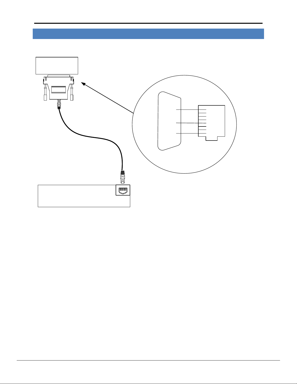
Port C VHLC RS-232
Interface Module
DB25F
7
3
2
8
7
6
5
4
3
1
VHLC
Server
RJ45
FieldServer
2
Tx
GND
Rx
FS-8915-10
8917-04
FieldServer
RJ45
Connect to one of the RS-232
Ports on the FieldServer
P1
18
3 HARDWARE CONNECTIONS
The FieldServer is connected to the VHLC as shown in the following connection drawing.
FieldServer Technologies 1991 Tarob Court Milpitas, California 95035 USA Web: www.fieldserver.com
Tel: (408) 262 2299 Fax: (408) 262 2269 Toll Free: (888) 509 1970 email: support@fieldserver.com
Page 5

FS-8700-133 Genisys Manual Page 5 of 13
Section Title
Data_Arrays
Column Title
Function
Legal Values
Data_Array_Name
Provide name for Data Array
Up to 15
alphanumeric
characters
Data_Array_Format
Provide data format. Each Data Array can only take on one
format.
Float, Bit, UInt16,
SInt16, Byte,
Data_Array_Length
Number of Data Objects. Must be larger than the data storage
area required by the Map Descriptors for the data being placed in
this array.
1-10,000
// Data Arrays
Data_Arrays
Data_Array_Name
,Data_Array_Format
,Data_Array_Length
DA_8I_01
,Byte
,32
DA_8O_01
,Byte
,32
DA_DI_01
,Bit
,256
DA_DO_01
,Bit
,256
DA_COS_01
,Byte
,1
DA_COS_02
,Byte
,1
4 CONFIGURING THE FIELDSERVER AS A GENISYS CLIENT
For a detailed discussion on FieldServer configuration, please refer to the FieldServer Configuration Manual. The
information that follows describes how to expand upon the factory defaults provided in the configuration files
included with the FieldServer (See “.csv” sample files provided with the FieldServer).
This section documents and describes the parameters necessary for configuring the FieldServer to communicate
with a Genisys Server.
4.1 Data Arrays/D escriptors
The configuration file tells the FieldServer about its interfaces, and the routing of data required. In order to enable
the FieldServer for Genisys communications, the driver independent FieldServer buffers need to be declared in the
“Data Arrays” section, the destination device addresses need to be declared in the “Client Side Nodes” section, and
the data required from the Servers needs to be mapped in the “Client Side Map Descriptors” section. Details on
how to do this can be found below.
Note that in the tables, * indicates an optional parameter, with the bold legal value being the default.
Example
FieldServer Technologies 1991 Tarob Court Milpitas, California 95035 USA Web: www.fieldserver.com
Tel: (408) 262 2299 Fax: (408) 262 2269 Toll Free: (888) 509 1970 email: support@fieldserver.com
Page 6

FS-8700-133 Genisys Manual Page 6 of 13
Section Title
Connections
Column Title
Function
Legal Values
Port
Specify which port the device is connected to the
FieldServer
P1-P81
Protocol
Specify protocol used
Genisys
Baud*
Specify baud rate
300 ,600, 1200, 2400, 4800, 9600 (Vendor
limitation)
Parity*
Specify parity
None, Even, Odd (Vendor limitation)
Data_Bits*
Specify data bits
8 (Vendor limitation)
Stop_Bits*
Specify stop bits
1, 2 (Vendor limitation)
Handshaking*
Specify hardware handshaking
None
Poll_Delay*
Time between internal polls
0-32000 seconds, 0.05 seconds
// // Client Side Connections
// Connections
Port
,Baud
,Data_Bits
,Stop_Bits
,Parity
,Protocol
P1
,9600
,8
,1
,None
,Genisys
4.2 Client Side Connect ion Descriptions
Example
1
Not all ports shown are necessarily supported by the hardware. Consult the appropriate Instruction manual for
details of the ports available on specific hardware.
FieldServer Technologies 1991 Tarob Court Milpitas, California 95035 USA Web: www.fieldserver.com
Tel: (408) 262 2299 Fax: (408) 262 2269 Toll Free: (888) 509 1970 email: support@fieldserver.com
Page 7

FS-8700-133 Genisys Manual Page 7 of 13
Section Title
Nodes
Column Title
Function
Legal Values
Node_Name
Provide name for Node
Up to 32
alphanumeric
characters
Node_ID
VHLC station address of physical Server Node
1-255
Protocol
Specify protocol used
Genisys
Connection
Specify which port the device is connected to the
FieldServer
P1-P81
Genisys_Check_Controls*
If OFF, the FieldServer configures VHLC to apply controls
from the FieldServer without verification.
If ON, the FieldServer configures VHLC to verify controls
supplied by the FieldServer before applying.
OFF, ON
Genisys_Intra_Poll_Delay*
Specify time, that FieldServer should wait before sending
ACK or Execute message after receiving the last character of
response from VHLC.
0.010s, 0.025s etc
// Client Side Nodes
// Nodes
Node_Name
,Node_ID
,Protocol
,Port
,Genisys_Check_Controls
,Genisys_Intra_Poll_Delay
Genisys_01
,1
,Genisys
,P1
,ON
,0.01s
Genisys_02
,2
,Genisys
,P1
,-
,0.01s
4.3 Client Side Node Descriptors
Example
FieldServer Technologies 1991 Tarob Court Milpitas, California 95035 USA Web: www.fieldserver.com
Tel: (408) 262 2299 Fax: (408) 262 2269 Toll Free: (888) 509 1970 email: support@fieldserver.com
Page 8

FS-8700-133 Genisys Manual Page 8 of 13
Column Title
Function
Legal Values
Map_Descriptor_Name
Name of this Map Descriptor
Up to 32 alphanumeric characters
Data_Array_Name
Name of Data Array where data is to be
stored in the FieldServer
One of the Data Array names from “Data
Array” section above
Data_Array_Offset
Starting location in Data Array
0 to maximum specified in “Data Array”
section above
Function
Function of Client Map Descriptor
COS_Poller, COS_Read , Wrbx
Column
Title
Function
Legal Values
Node_Name
Name of Node to fetch data from
One of the Node names
specified in “Client Node
Descriptor” above
Data_Type*
‘Bit’ each byte of Indication statuses will be stored in 8 consecutive
locations in the Data Array. Similarly while writing; Control byte
will be composed from 8 consecutive locations of the Dara Array.
‘Byte’ each byte of Indication statuses will be stored as an 8-Bit
Integer at the specified location. Similarly while writing; Control
byte will be composed from a single location of the Data Array.
Refer to Appendix A.1
Bit, Byte
Address*
Internally used parameter, if used specify value 0
0
Length*
Length of Map Descriptor
Number of indications to store or number of controls to write as
per Data_Type.
Bit: 1-256, 8
Byte: 1-32, 1
Column Title
Function
Legal Values
Scan_Interval
Rate at which data is polled
≥0.001s
4.4 Client Side Map Descriptor s
4.4.1 FieldServer Related Map D escriptor P arameters
4.4.2 Driver Related Map Descriptor Parameters
4.4.3 Timing Parameters
FieldServer Technologies 1991 Tarob Court Milpitas, California 95035 USA Web: www.fieldserver.com
Tel: (408) 262 2299 Fax: (408) 262 2269 Toll Free: (888) 509 1970 email: support@fieldserver.com
Page 9

FS-8700-133 Genisys Manual Page 9 of 13
// Client Side Map Descriptors
//
Map_Descriptors
Map_Descriptor_Name
,Scan_Interval
,Data_Array_Name
,Data_Array_Offset
,Function
,Node_Name
,Data_Type
,Address
,Length
CMD_01
,1.00s
,DA_COS_01
,0
,COS_Poller
,Genisys_01
,Byte
,0
,1
CMD_01a
,50s
,DA_8I_01
,0
,COS_Read
,Genisys_01
,Byte
,0
,32 CMD_02
,1.00s
,DA_COS_02
,0
,COS_Poller
,Genisys_02
,Bit
,0
,1
CMD_02a
,50s
,DA_DI_01
,0
,COS_Read
,Genisys_02
,Bit
,0
,256
Name of one of the Data
Arrays defined in the
Data_Array section.
Indication statuses will be
stored in this Data Array
Starting offset
in Data Array to
hold 1st
indication
status
One of the Nodes
declared in Node
Section. Indications
will be read from the
station address
Frequency (in
seconds) to read
Indication Statuses
Number of consecutive
locations in the Data array
to be used for storing data
from the Server.
4.5 Map Descriptor Example: Read Indications
The following Map Descriptors will read indication words from physical Server Genisys_01 and Genisys_02 (described in Client Side Node Descriptors section).
The Cos_Poller Map Descriptor polls VHLC for any indication word changes and returned data is stored on the Data Array under the COS_READ Map Descriptor
for the same Node. The rate of polling is determined by the Scan_Interval.
The Cos_Read Map Descriptor also polls VHLC for all indication words irrespective of data change. The rate of polling is determined by the Scan_Interval.
If Data_Type is Byte, any location in Data Array will hold one indication word from VHLC.
If Data_Type is Bit, eight consecutive locations in Data Array will hold one indication word from VHLC. Also see Appendix A.1.
FieldServer Technologies 1991 Tarob Court Milpitas, California 95035 USA Web: www.fieldserver.com
Tel: (408) 262 2299 Fax: (408) 262 2269 Toll Free: (888) 509 1970 email: support@fieldserver.com
Page 10

FS-8700-133 Genisys Manual Page 10 of 13
// Client Side Map Descriptors
//
Map_Descriptors
Map_Descriptor_Name
,Scan_Interval
,Data_Array_Name
,Data_Array_Offset
,Function
,Node_Name
,Data_Type
,Address
,Length
CMD_01b
,-
,DA_8O_01
,0
,Wrbx
,Genisys_01
,Byte
,0
,32
CMD_02
,-
,DA_DO_01
,0
,Wrbx
,Genisys_02
,Bit
,0
,256
Name of one of
the Data Arrays
defined in
Data_Array
section. This
Data Array holds
control statuses
to be written to
other devices.
Starting offset
in the Data
Array which
holds the 1st
control status.
One of the
Nodes declared
in the Node
Section.
Indications will
read from the
station address
belonging to this
Node
Number of consecutive
locations in the Data
array to use when
issuing the Write
command.
Wrbx: send write command
to the Server when the
associated Controls updates
or changes. To write
continuously use Wrbc as the
function and add a
Scan_Interval parameter to
configure how often to write.
4.6 Map Descriptor Example: Write Controls
The following Map Descriptor will write controls to physical Server Genisys_01 and Genisys_02 (described in Client Side Node Descriptors section) whenever
any of the control statuses changes/updates. One such Map Descriptor is required per Node.
If Data_Type is Byte, 32 consecutive locations from the Data Array will be written to VHLC. Data at any location would be considered as one control word.
If Data_Type is Bit, 256 consecutive locations from the Data Array will be written to VHLC. Data at 8 consecutive locations would be considered as one control
word.
Also see Appendix A.1.
FieldServer Technologies 1991 Tarob Court Milpitas, California 95035 USA Web: www.fieldserver.com
Tel: (408) 262 2299 Fax: (408) 262 2269 Toll Free: (888) 509 1970 email: support@fieldserver.com
Page 11

FS-8700-133 Genisys Manual Page 11 of 13
5 CONFIGURING THE FIELDSERVER AS A GENISYS SERVER
The Server side has been implemented only for FieldServer’s quality assurance requirements.
FieldServer Technologies 1991 Tarob Court Milpitas, California 95035 USA Web: www.fieldserver.com
Tel: (408) 262 2299 Fax: (408) 262 2269 Toll Free: (888) 509 1970 email: support@fieldserver.com
Page 12

FS-8700-133 Genisys Manual Page 12 of 13
Appendix A. Advanced Topics
Appendix A.1. Storage Structure for Data Type Bit and Byte
LSB bit in Indication/Control Byte is the1
If the Data_Type is ‘Byte’ and only the 1
st
status/control value
st
and 2nd indication status values are 1 (out of 8 statuses), all
others being zero, the Driver will store a numeric value of 3 in the Data Array.
FieldServer Technologies 1991 Tarob Court Milpitas, California 95035 USA Web: www.fieldserver.com
Tel: (408) 262 2299 Fax: (408) 262 2269 Toll Free: (888) 509 1970 email: support@fieldserver.com
Page 13

FS-8700-133 Genisys Manual Page 13 of 13
Error
Description
Action
GENISYS:#1 FYI.
Connection params are
%d %d %d Even
If a connection is declared in
section 4.2 without Baud,
Data_Bits, Stop_Bits or Parity, the
displayed parameter values will be
in use.
Check if connection parameter matches the
setting at VHLC.
GENISYS:#2 FYI. MD
required to store data
from Node(%d)
A Map Descriptor with function
COS_Poller has been declared for
a Node but the COS_Read Map
Descriptor required to store the
data is missing.
Edit configuration file and add Map Descriptor
with COS_Read function.
GENISYS:#3 FYI. MD(%s)
length required=%d, now
Only %d statuses will be
stored
The COS_Read Map Descriptor is
of insufficient length to store all
indication words from VHLC.
If all indication words need to be stored, edit
the configuration file and change the length of
the Map Descriptor to the reported value.
GENISYS:#4 ERR %dth
word number %d is
invalid
The indication data response from
VHLC contains an invalid word
number.
Valid range is 0-31
No data will be stored.
Call tech support.
GENISYS:#5 FYI.
Indications can not be
written
The FieldServer received an
instruction from a Server device to
write indications to VHLC.
FieldServer can only write controls
to VHLC.
Inspect the configuration file to determine
whether the Data Array under the COS_Poller
or COS_Read Map Descriptor is mapped to
receive write commands from other protocols.
Also check that other devices are not
configured to write data to these Data Arrays.
GENISYS:#11FYI. MD(%s)
length required=%d, now
Only %d statuses will be
stored
The Driver is acting as a Server
rather than a Client.
Call tech support.
GENISYS:#12 ERR %dth
word number %d is
invalid
The Driver is acting as a Server
rather than a Client.
Call tech support.
Appendix B. Error Messages
Most error messages are associated with errors in parsing an incoming message from the VHLC panel. The most
likely cause is a mismatch in expected message format. The driver will flag one of the following error messages
and continue. In most cases the message currently being processed by the driver will also be printed so that any
problems can be easily diagnosed.
The following Error Messages appear upon the ‘Driver Messages’ Screen
%d means numeric number
%s means string
Messages number 2, 3 and 11 will be displayed just once if generated after rebooting or power cycling the
FieldServer.
FieldServer Technologies 1991 Tarob Court Milpitas, California 95035 USA Web: www.fieldserver.com
Tel: (408) 262 2299 Fax: (408) 262 2269 Toll Free: (888) 509 1970 email: support@fieldserver.com
 Loading...