

Page 1
Driver Version:
1.00
Document Revision:
5
APPLICABILITY & EFFECTIVITY
Effective for all systems manufactured after April 2010
Driver Manual
(Supplement to the FieldServer Instruction Manual)
FS-8700-123 MetOne Particle Counter
HACH Ultra Analytics
(formerly Pacific Scientific Instruments)
Standard Protocol FX (enhanced) - ENG110
A Sierra Monitor Company
Page 2

FS-8700-123 MetOne Particle Counter Serial Driver Manual Table of Contents
TABLE OF CONTENTS
1 MetOne Particle Counter Serial Description ................................................................................................... 3
2 Driver Scope of Supply ................................................................................................................................... 3
2.1 Supplied by FieldServer Technologies for this driver ..................................................................................... 3
3 Hardware Connections ................................................................................................................................... 4
3.1 Connection to 2100 Particle Counter ............................................................................................................ 4
3.2 Connection to 4308 Particle Counter ............................................................................................................ 5
3.3 Hardware Connection Tips / Hints ................................................................................................................. 5
4 Data Array Parameters ................................................................................................................................... 6
5 Configuring the FieldServer as a MetOne PC Serial Client ............................................................................... 7
5.1 Client Side Connection Descriptions .............................................................................................................. 7
5.2 Client Side Node Descriptors ......................................................................................................................... 8
5.3 Client Side Map Descriptors........................................................................................................................... 9
5.3.1 FieldServer Related Map Descriptor Parameters ................................................................................... 9
5.3.2 Driver Related Map Descriptor Parameters ........................................................................................... 9
5.3.3 Timing Parameters ................................................................................................................................. 9
5.4 Map Descriptor Example 1 – Read Hold ( or Sample) Times from a Device. ............................................... 10
5.5 Map Descriptor Example 2 – Write Hold (or Sample) Times to a Device. ................................................... 11
5.6 Map Descriptor Example 3 – Read the operating mode. ............................................................................. 11
5.7 Map Descriptor Example 4 – Start / Stop Counting. .................................................................................... 12
5.8 Map Descriptor Example 5 – Change Mode ................................................................................................ 12
5.9 Map Descriptor Example 6 – Select Device ................................................................................................. 13
5.10 Map Descriptor Example 7 – Read the Current Record ............................................................................... 14
5.11 Map Descriptor Example 8 – Dumping the Current Record ........................................................................ 14
5.12 Map Descriptor Example 9 – An alternate way of storing the current record. ........................................... 15
5.13 Map Descriptor Example 10 – Reading from a SubDevice/Port .................................................................. 16
5.14 Map Descriptor Example 11 – Selecting a Sub-Device/Port ........................................................................ 16
6 Configuring the FieldServer as a MetOne PC Serial Server ............................................................................ 17
Appendix A. Useful Features ................................................................................................................................ 18
Appendix A.1. Driver Operating and Error Statistics ............................................................................................... 18
Appendix B. Troubleshooting ............................................................................................................................... 19
Appendix B.1. Driver Error Messages ...................................................................................................................... 19
Appendix B.2. Driver Exposed Operating and Error Statistics ................................................................................. 21
Appendix B.3. Sample and Hold Times .................................................................................................................... 22
FieldServer Technologies 1991 Tarob Court Milpitas California 95035 USA Web: www.fieldserver.com
Tel: (408) 262 2299 Fax: (408) 262 2269 Toll Free: (888) 509 1970 email: support@fieldserver.com
Page 3
FS-8700-123 MetOne Particle Counter Driver Manual Page 3 of 22
FieldServer
mode
Nodes
Comments
Client
1
There can only be one Client node per FieldServer port. The driver can poll any number
of Server nodes provided that they comply with the vendors numbering requirements
Server
Driver as a Server is not documented or supported. Used only for QA purposes.
FieldServer Technologies PART #
Description
FS-8917-16
RJ45 to terminal connector cable.
FS-8917-02
RJ45 to DB9F connector adapter
1 METONE PARTICLE COUN TER SERIAL DESCRIPTION
The MetOne Particle Counter Serial driver allows the FieldServer to transfer data to and from devices over RS-232
or RS-485 using MetOne Particle Counter Serial protocol.
This driver is based on a specification called “Standard Protocol FX (enhanced)” ENG110 Revision A dated 1999 by
Pacific Scientific Instruments. This protocol provides an interface to Particle Counters manufactured by HACH Ultra
Analytics and labeled as METONE products. Pacific Scientific Instruments is a former name of Hach.
The primary purpose of the driver is to obtain the current particle counts but it does allow for limited control and
configuration of some counter parameters. The Server side of the driver is intended to support FieldServer’s
Quality Assurance program and is not intended to provide complete emulation of a MetOne Counter.
When configured as a Client the driver can start/stop a unit from sampling change its mode set and get sample and
hold times startup or standby a unit and retrieve its current sample value. Whenever the driver stores a sample
value it will also store a timestamp of when the record was obtained.
In the configuration of the FieldServer each device is identified by specifying its device number then the sub-device
code or port number and finally by a device type. The device type will be used to interpret the status byte obtained
from the device.
For each configured node each time the FieldServer sends a message to the device it will select the device (and the
select the sub-device or port if specified) and then the message will be sent. If the most recent message sent was
sent to the device the driver will do the selection to ensure the correct device response.
When the current record is read from a device then the driver will store the data extracted from the response in a
range of consecutive Data Array elements so that these values can be served to another protocol. Even though the
record data contains a time stamp the driver will make its own time stamp for new data. If there is no current
record the driver will not update the data.
If the response is invalid in any way – invalid characters or invalid checksum the driver will ignore the message and
not store any data.
Max Nodes Supported
2 DRIVER SCOPE OF SUPP LY
2.1 Supplied by Fiel dServer Technologie s for this driver
FieldServer Technologies 1991 Tarob Court Milpitas California 95035 USA Web: www.fieldserver.com
Tel: (408) 262 2299 Fax: (408) 262 2269 Toll Free: (888) 509 1970 email: support@fieldserver.com
Page 4

FS-8700-123 MetOne Particle Counter Driver Manual Page 4 of 22
R2 R1
Gnd
_
+
Gnd
FG
_
+
RS-485
Opto
Isolated
FieldServer
P1
18
6
9-Pin Serial Connector on
rear of 2100 Device
1 2
98754
3
Rx
/
-
Tx
/+
COM
FieldServer Part #
8917-16
Pigtail for RJ45
Port
Brown
Blue/white
Orange/White
6
9-Pin Serial Connector on rear
of 2100 Device
1 2 987543
Tx Rx GND
OR
FS Function
RJ45 Pin#
2100 Pin
2100 Function
Color
RX 1 2
Tx
Brown
Tx 2 3
Rx
Orange/White
COM
3 7 GND
Blue/White
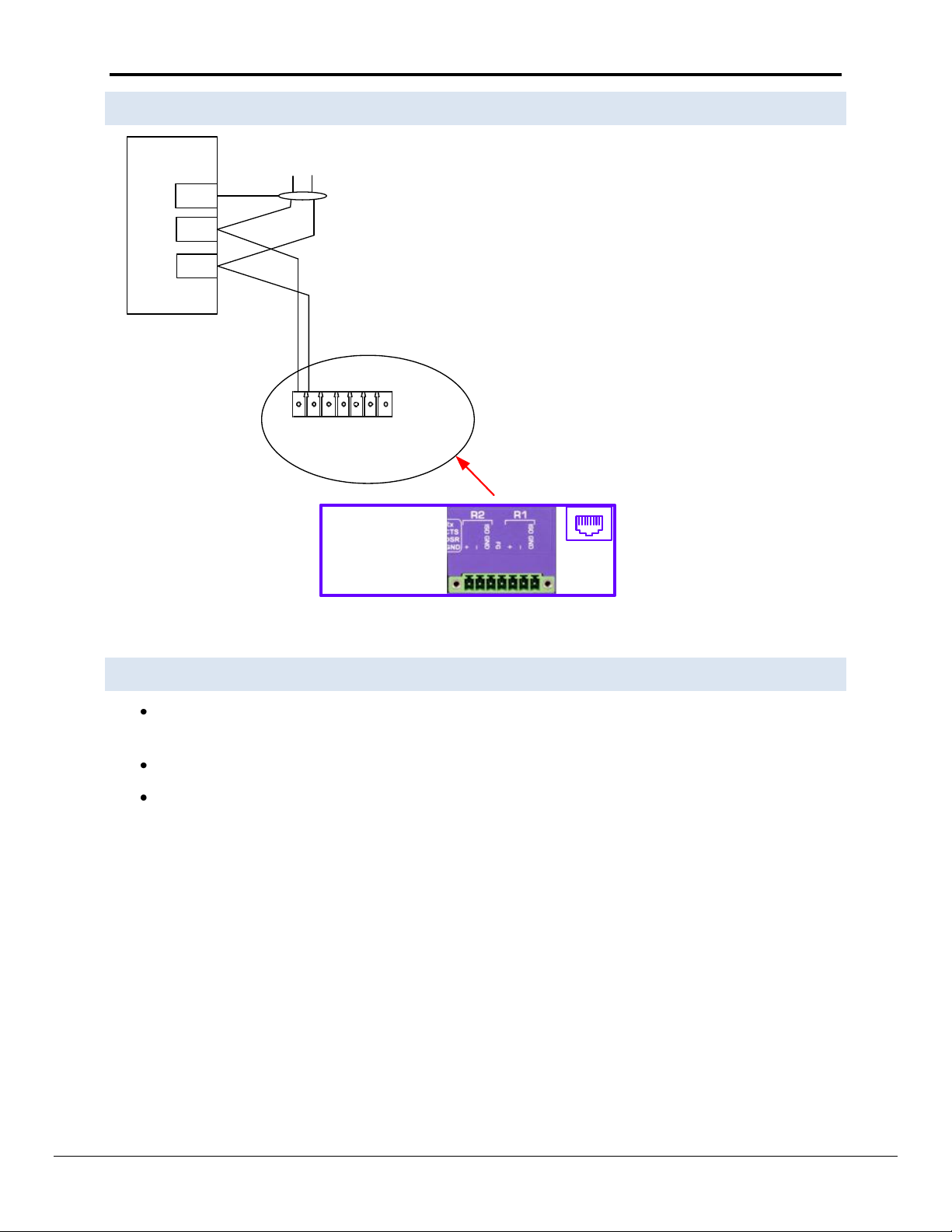
3 HARDWARE CONNECTIONS
3.1 Connection to 2100 Particle Counter
Connector Pinouts
FieldServer Technologies 1991 Tarob Court Milpitas California 95035 USA Web: www.fieldserver.com
Tel: (408) 262 2299 Fax: (408) 262 2269 Toll Free: (888) 509 1970 email: support@fieldserver.com
Page 5
FS-8700-123 MetOne Particle Counter Driver Manual Page 5 of 22
R2 R1
Gnd
_
+
Gnd
FG
_
+
RS-485
Opto
Isolated
FieldServer
P1
18
8
6
13
Part of 4308
Device
Back of Board
3.2 Connection to 4308 Particle Counter
3.3 Hardware Connection Tips / Hints
The 2100 Device auto configures its serial port based on the pins connected. There is no explicit setting or
selector for RS-232/RS-485
Ensure other pins are not connected.
The FS-8917-16 cable is not needed for RS-485 on the X30 and X40 only.
FieldServer Technologies 1991 Tarob Court Milpitas California 95035 USA Web: www.fieldserver.com
Tel: (408) 262 2299 Fax: (408) 262 2269 Toll Free: (888) 509 1970 email: support@fieldserver.com
Page 6
FS-8700-123 MetOne Particle Counter Driver Manual Page 6 of 22
Section Title
Data_Arrays
Column Title
Function
Legal Values
Data_Array_Name
Provide name for Data Array
Up to 15
alphanumeric
characters
Data_Array_Format
Provide data format. Each Data Array can only take on one
format.
FLOAT BIT UInt16
SInt16 Byte.
Data_Array_Length
Number of Data Objects. Must be larger than the data storage
area required by the Map Descriptors for the data being placed in
this array.
1-10 000
// Data Arrays
Data_Arrays
Data_Array_Name
, Data_Array_Format
, Data_Array_Length
DA_AI_01
, UInt16
, 200
DA_AO_01
, UInt16
, 200
DA_DI_01
, Bit
, 200
DA_DO_01
, Bit
, 200
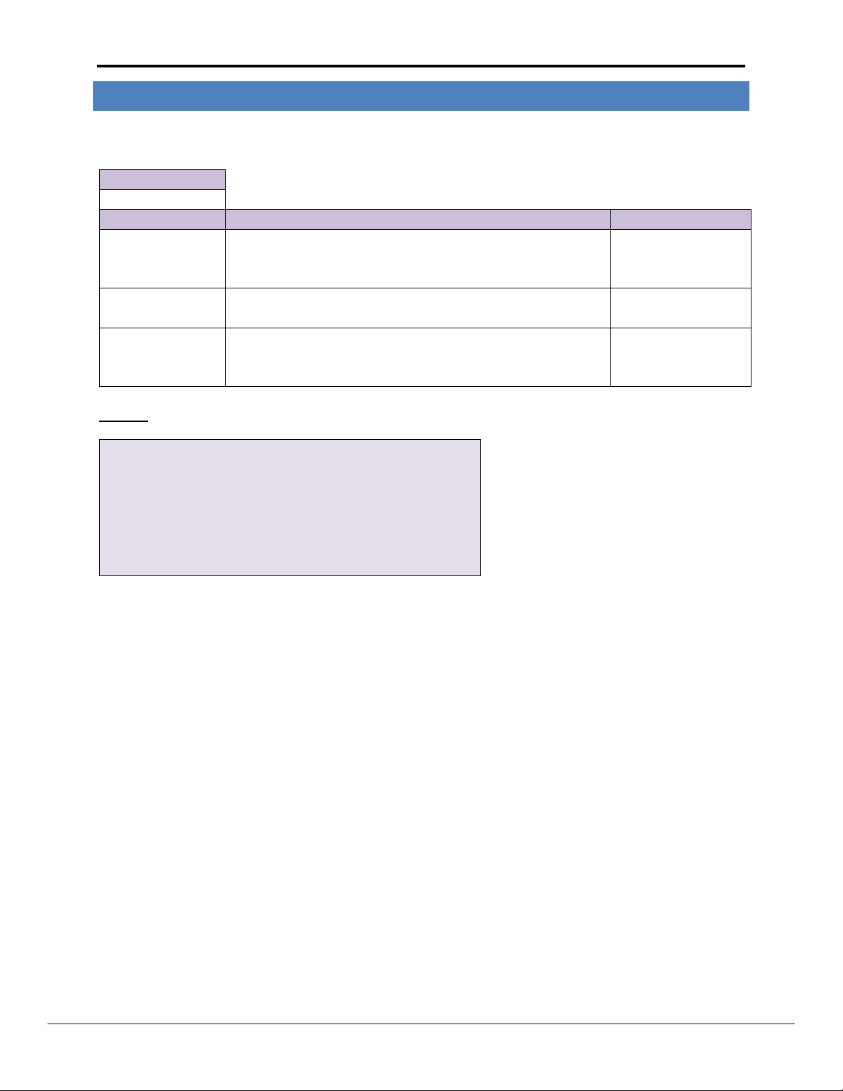
4 DATA ARRAY PARAMETER S
Data Arrays are “protocol neutral” data buffers for storage of data to be passed between protocols. It is necessary
to declare the data format of each of the Data Arrays to facilitate correct storage of the relevant data.
Example
FieldServer Technologies 1991 Tarob Court Milpitas California 95035 USA Web: www.fieldserver.com
Tel: (408) 262 2299 Fax: (408) 262 2269 Toll Free: (888) 509 1970 email: support@fieldserver.com
Page 7
FS-8700-123 MetOne Particle Counter Driver Manual Page 7 of 22
Section Title
Connections
Column Title
Function
Legal Values
Port
Specify which port the device is connected to the FieldServer
P1-P8 R1-R21
Protocol
Specify protocol used
MetOne
Baud*
Specify baud rate
9600 (Vendor limitation).
Parity*
Specify parity
None (Vendor limitation)
Data_Bits*
Specify data bits
8 (Vendor limitation)
Stop_Bits*
Specify stop bits
1 (Vendor limitation)
Poll_Delay*
Time between internal polls
0-32000 seconds 0.05s
// Client Side Connections
Connections
Port
, Protocol
, Baud
, Parity
, Poll_Delay
P8
, MetOne
, 9600
, None
, 0.100s
5 CONFIGURING THE FIELDSERVER AS A METONE PC SERIAL CLIENT
For a detailed discussion on FieldServer configuration please refer to the FieldServer Configuration Manual. The
information that follows describes how to expand upon the factory defaults provided in the configuration files
included with the FieldServer (See “.csv” sample files provided with the FieldServer).
This section documents and describes the parameters necessary for configuring the FieldServer to communicate
with a MetOne Particle Counter Serial Server.
The configuration file tells the FieldServer about its interfaces and the routing of data required. In order to enable
the FieldServer for MetOne Particle Counter Serial communications the driver independent FieldServer buffers
need to be declared in the “Data Arrays” section the destination device addresses need to be declared in the
“Client Side Nodes” section and the data required from the Servers needs to be mapped in the “Client Side Map
Descriptors” section. Details on how to do this can be found below.
Note that in the tables * indicates an optional parameter with the bold legal value being the default.
5.1 Client Side Co nnection Descriptions
Example
1
Not all ports shown are necessarily supported by the hardware. Consult the appropriate Instruction manual for details of the ports available
on specific hardware.
FieldServer Technologies 1991 Tarob Court Milpitas California 95035 USA Web: www.fieldserver.com
Tel: (408) 262 2299 Fax: (408) 262 2269 Toll Free: (888) 509 1970 email: support@fieldserver.com
Page 8

FS-8700-123 MetOne Particle Counter Driver Manual Page 8 of 22
Section Title
Nodes
Column Title
Function
Legal Values
Node_Name
Provide name for node
Up to 32 alphanumeric
characters
Node_ID
The ‘Device’ Number
1-64
Protocol
Specify protocol used
MetOne.
Connection
Specify which port the device is connected to the FieldServer
P1-P8 R1-R21
PLC_Type
Identifies for the driver the family of Particle
Counters/Manifolds connected to.
“237 Family”
“2408” or “Manifold”
“4800”
“HF CNC”
Nodes
Node_Name
, Node_ID
, Protocol,
, PLC_Type
, Connection
PLC, 1
, 1
, MetOne
, 237, Family
, P1
5.2 Client Side No de Descripto rs
Example
FieldServer Technologies 1991 Tarob Court Milpitas California 95035 USA Web: www.fieldserver.com
Tel: (408) 262 2299 Fax: (408) 262 2269 Toll Free: (888) 509 1970 email: support@fieldserver.com
Page 9

FS-8700-123 MetOne Particle Counter Driver Manual Page 9 of 22
Column Title
Function
Legal Values
Map_Descriptor_Name
Name of this Map Descriptor
Up to 32 alphanumeric characters
Data_Array_Name
Name of Data Array where data is to be
stored in the FieldServer
One of the Data Array names from
Section 4
Data_Array_Offset
Starting location in Data Array
0 to (Data_Array_Length -1) as specified
in Section 4
Function
Function of Client Map Descriptor
Rdbc, Wrbc, Wrbx
Column Title
Function
Legal Values
Node_Name
Name of Node to fetch data from
One of the node names specified
in “Client Node Descriptor”
above
Length
Length of Map Descriptor
See Map Descriptor Example for
recommended lengths
Met1_Function
Specify the function. Additional notes and
explanations are provided in the examples. Refer
also to Appendix B.3
Hold Time, Mode, Count, Device
Select, Current Record,
SubDevice/Port Select
DA_Byte_Name*
A secondary Data Array is specified using this
parameter. The driver stores the read current
record response byte for byte in the secondary
Data Array.
One of the Data Array names
from Section 4
Met1_SubDev_or_Port*
This parameter must be specified in conjunction
with the Address Parameter if a SubDevice or Port
is being polled.
Device, SubDevice, Port
Address*
This parameter is used to specify the SubDevice or
Port number if either is being polled.
Port numbers: 0-63 SubDevice
numbers: 1-64
Met1_Label*
A method of storing count data using a 3-character
label. Use of this parameter to allows the driver to
know which count to store. Refer to example in
Section 5.12
Any 3 character label
programmed by the user to
identify the sample point – e.g.
0.1
LOC, FLO, DATETIME.
Column Title
Function
Legal Values
Scan_Interval
Rate at which data is polled
≥0.001s
5.3 Client Side Map Descripto rs
5.3.1 FieldServer Related Ma p Descriptor Parameters
5.3.2 Driver Related Map Descriptor Param eters
5.3.3 Timing Paramete rs
FieldServer Technologies 1991 Tarob Court Milpitas California 95035 USA Web: www.fieldserver.com
Tel: (408) 262 2299 Fax: (408) 262 2269 Toll Free: (888) 509 1970 email: support@fieldserver.com
Page 10

FS-8700-123 MetOne Particle Counter Driver Manual Page 10 of 22
//, , , , Client, Side, Map, Descriptors
Map_Descriptors
Map_Descriptor_Name
, Data_Array_Name
, Data_Array_Offset
, Function
, Node_Name
, Met1_Function
, Length
, Scan_Interval
Read_Time
, DA_TIMES
, 0
, Rdbc
, MET1
, Hold Time,
, 3
, 5.0s
While not
mandatory giving
each Map
Descriptor a
unique name will
help to diagnose
configuration
problems.
The name of the Node. The driver uses this
name to link the Map Descriptor to a Node
Descriptor (where it finds the Device Number
specified with the Node_ID parameter). The
Node Descriptor provides a link to the
connection.
Tells the driver
to read the Hold
Time from the
This task must be
executed every 5
seconds.
When a response
is received the
driver extracts the
data and stores it
in the Data Array
named here
starting at the
location specified
by the offset
parameter.
Tells the driver
to Read
continuously.
Reserves 3 Data
array locations
for storing data.
5.4 Map Descriptor Example 1 – Read Hold ( or Sample ) Times from a Device .
(Important Note: See Appendix B.3
In this example the driver reads the hold time from the field device. To read Sample Times simply change the Met1_Function to ‘Sample Time.
FieldServer Technologies 1991 Tarob Court Milpitas California 95035 USA Web: www.fieldserver.com
Tel: (408) 262 2299 Fax: (408) 262 2269 Toll Free: (888) 509 1970 email: support@fieldserver.com
Page 11

FS-8700-123 MetOne Particle Counter Driver Manual Page 11 of 22
//, , , , Client, Side, Map, Descriptors
Map_Descriptors
Map_Descriptor_Name
, Data_Array_Name
, Data_Array_Offset
, Function
, Node_Name
, Met1_Function
, Length
Write_Time
, DA_TIMES
, 0
, Wrbx
, MET1
, Hold Time,
, 1
//, , , , Client, Side, Map, Descriptors
Map_Descriptors
Map_Descriptor_Name
, Data_Array_Name
, Data_Array_Offset
, Function
, Node_Name
, Met1_Function
, Length
, Scan_Interval
Write_Time
, DA_MODE
, 0
, Rdbc
, MET1
, Mode
, 1
, 1.0s
The driver will extract the time in
seconds from the Data Array
specified here and use it to form the
command message to the field
device.
The location in
the Data Array
This function ‘Wrbx’ tells the driver
to only send the command each
time the value found in the
specified DA:offset is updated.
Update means each time some
other protocol writes to this
DA:offset
Change this to
‘Sample Time’ to
command a sample
time or make two
Map Descriptors –
each with the correct
time function.
Tells the
FieldServer that
one element of
the data array is
reserved for this
Map Descriptor.
5.5 Map Descriptor Example 2 – Write Hold (or Sa mple) Times to a De vice.
(Important Note: See Appendix B.3
In this example the driver writes the hold time to the field device. The time is specified in seconds. A max of 23 hours 59 minutes and 59 seconds can be
specified. To write Sample Times simply change the Met1_Function to ‘Sample Time. The driver extracts a single value from the specified Data Array. It treats
this value as the number of seconds. Thus to specify a sample time of 1 hour 2 minutes and 3 seconds load the Data Array with 3723.
5.6 Map Descriptor Example 3 – Read the operating mode.
In this example the driver reads the operating mode from the field device. The driver stores a single element of data extracted from the response. The driver
stores a ‘C’ to indicate the field device is counting a ‘H’ to indicate the device is holding and an ‘S’ to indicate that it has stopped. If the mode is not recognized
the driver stores a ‘?’. If another protocol reads these states from the FieldServer it will probably display the ASCII value corresponding to each mode letter:
‘C’=67 ‘H’=72 and ‘S’=83
FieldServer Technologies 1991 Tarob Court Milpitas California 95035 USA Web: www.fieldserver.com
Tel: (408) 262 2299 Fax: (408) 262 2269 Toll Free: (888) 509 1970 email: support@fieldserver.com
Page 12

FS-8700-123 MetOne Particle Counter Driver Manual Page 12 of 22
//, , , , Client, Side, Map, Descriptors
Map_Descriptors
Map_Descriptor_Name
, Data_Array_Name
, Data_Array_Offset
, Function
, Node_Name
, Met1_Function
, Length
, Scan_Interval
Write_Count_Mode
D, A_COUNT_CTRL
, 0
, Wrbx
, MET1
, Count
, 1
, 1.0s
//, , , , Client, Side, Map, Descriptors
Map_Descriptors
Map_Descriptor_Name
, Data_Array_Name
, Data_Array_Offset
, Function
, Node_Name
, Met1_Function
, Length
Write_Mode
, DA_MODE_CTRL
, 0
, Wrbx
, MET1
, Mode
, 1
Set length to 1 for this
Met1_Function
Driver extracts one single value from this Data Array Offset and uses the value to send a
command to change the mode.
Auto Sample Mode: Value=1 Manual Sample Mode: Value=2
Active Mode : Value = 3 Standby Mode: Value = 4
If the value found is not valid then no command is sent.
When the function is
Wrbx then the scan
interval parameter is
ignored.
Set length to 1
for this
Met1_Function
Command is sent each
time the value at
Data_Array_Offset is
updated.
Driver extracts one single value from this DA:Offset and uses the value to
send a command to start counting (value=1 tells device to start counting in
computer mode and value=2 tells the device to start counting in auto
mode using its preset sample and hold times.) or stop counting (zero value)
5.7 Map Descriptor Example 4 – Start / Stop Count ing.
In this example the driver sends a command to start or stop the field device from counting based on the value found in the Data Array element. If the value is
non-zero the field device will be commanded to start counting. If the value is zero the field device will be commanded to stop counting. In this example the
function is set to Wrbx which means the command message will be sent each time the value found at the specified offset in the specified Data Array is updated
even if it is not changed.
5.8 Map Descriptor Example 5 – Change Mode
In this example the driver sends a command to change the mode of the field device. The command sent is determined by the value found in the specified Data
Array location. In this example the function is set to Wrbx. This means the command message will be sent each time the value found at the specified offset in
the specified Data Array is updated even if it is not changed
FieldServer Technologies 1991 Tarob Court Milpitas California 95035 USA Web: www.fieldserver.com
Tel: (408) 262 2299 Fax: (408) 262 2269 Toll Free: (888) 509 1970 email: support@fieldserver.com
Page 13

FS-8700-123 MetOne Particle Counter Driver Manual Page 13 of 22
// Client Side Map Descriptors
Map_Descriptors
Map_Descriptor_Name
, Data_Array_Name
, Data_Array_Offset
, Function
, Node_Name
, Met1_Function
, Length
Select Device
, DA_MODE_CTRL
, 0
, Wrbx
, MET1
, Device Select
, 1
Set length to 1 for this
Met1_Function
The Node_Name connects this Map Descriptor to the Node Descriptor
and that is where the driver finds the Node_ID parameter.
5.9 Map Descriptor Example 6 – Selec t Device
Device selection is handled automatically by the driver and support for this message is provided mainly for testing purposes. The driver uses the Node_ID
parameter to learn the address/number of the device to be selected. Valid numbers are in the range 1...64. When the device responds, the driver stores the
device number in the Data Array element specified in the configuration.
FieldServer Technologies 1991 Tarob Court Milpitas California 95035 USA Web: www.fieldserver.com
Tel: (408) 262 2299 Fax: (408) 262 2269 Toll Free: (888) 509 1970 email: support@fieldserver.com
Page 14

FS-8700-123 MetOne Particle Counter Driver Manual Page 14 of 22
// Client Side Map Descriptors
Map_Descriptors
Map_Descriptor_Name
, Data_Array_Name
, Data_Array_Offset
, Function
, Node_Name
, Met1_Function
, Length
, Scan_Interval
Read Record
, DA_DATA
, 0
, Rdbc
, MET1
, Current Record
, 20
, 1.0s
Offset
0 1 2 3 4 5 6 7 8 9 10
...
Data
Status Byte
Date - Month
Date - Day
Date - Year
Time - Hours
Time - Minutes
Time - Seconds
Period
Count #1
Count #2
Count #3
...
Map_Descriptors
Map_Descriptor_Name
, Data_Array_Name
, Data_Array_Offset
, DA_Byte_Name
, Function
, Node_Name
, Met1_Function
, Length
, Scan_Interval
Read Record
, DA_DATA
, 0
, DA_DUMP
, Rdbc
, MET1
, Current Record
, 20
, 1.0s
The length must be set to a value large enough to store the 8
fixed data items and the variable number of count fields.
Driver stores the current record information in the Data Array
specified here starting at the specified offset. The data is arranged as
depicted in the following table.
A secondary Data Array is specified with the ‘DA_Byte_Name’ parameter.
When this is done the driver stores the read current record response byte for
byte in the secondary DA.
The length specified the amount of Data
Array space reserved for primary
storage and has no effect on the dump.
Ensure that dumps don’t overlap.
5.10 Map D escriptor E xample 7 – Read the Current Record
In this example the driver reads the current record and stores the values in the specified Data Array. A single record comprises status; date, time and a count
for 1 or more locations. The driver has no advance knowledge of the number of count fields to expect in the response. It simply stores up to a maximum of 20
count fields in consecutive locations in the Data Arrays. To map these counts to a Client protocol the order of the count fields must be known. The Map
Descriptor length must be set to a value that allows for enough data to be stored bearing in mind that it requires 8 Data Array elements to store the status date
and time and period. One of these Map Descriptors is required for each device from which the current record is to be read.
5.11 Map D escriptor E xample 8 – Dumping the Current Record
In this example a secondary Data Array has been specified. Each time a response is received the driver dumps the response byte for byte the secondary Array
in addition to the storage specified in the previous example. It is important to avoid overlaps in the secondary arrays if this feature is used on multiple Map
Descriptors. We suggest that about 2-300 DA elements is made available for the dump and that the format of the secondary Data Array is ‘BYTE’
FieldServer Technologies 1991 Tarob Court Milpitas California 95035 USA Web: www.fieldserver.com
Tel: (408) 262 2299 Fax: (408) 262 2269 Toll Free: (888) 509 1970 email: support@fieldserver.com
Page 15

FS-8700-123 MetOne Particle Counter Driver Manual Page 15 of 22
Map_Descriptors
Map_Descriptor_Name
, Scan_Interval
, Data_Array_Name
, Data_Array_Offset
, Length
, DA_Byte_Name
, Function
, Node_Name
, Met1_Function
, Met1_SubDev_or_Port
Rd_CurretVals
, 0s
, DA_CURR_D01
, 0
, 20
, DA_DUMP_D01
, Rdbc
, MET1
, Current Record
, Device
Map_Descriptors
Map_Descriptor_Name
, Scan_Interval
, Data_Array_Name
, Data_Array_Offset
, Length
, Function
, Node_Name
, Met1_Function
, Met1_SubDev_or_Port
, Met1_Label
Rd_CurretVals1
, 0s
, DA_CURR_D01_LBL
, 0
, 1
, Passive
, MET1
, Current Record
, Device
, 0.1
Rd_CurretVals2
, 0s
, DA_CURR_D01_LBL
, 1
, 1
, Passive
, MET1
, Current Record
, Device
, 0.3
Rd_CurretVals3
, 0s
, DA_CURR_D01_LBL
, 2
, 1
, Passive
, MET1
, Current Record
, Device
, 0.5
Rd_CurretVals4
, 0s
, DA_CURR_D01_LBL
, 3
, 1
, Passive
, MET1
, Current Record
, Device
, 1.0
Rd_CurretVals5
, 0s
, DA_CURR_D01_LBL
, 4
, 1
, Passive
, MET1
, Current Record
, Device
, 3.0
Rd_CurretVals6
, 0s
, DA_CURR_D01_LBL
, 5
, 1
, Passive
, MET1
, Current Record
, Device
, 5.0
Rd_CurretVals7
, 0s
, DA_CURR_D01_LBL
, 6
, 1
, Passive
, MET1
, Current Record
, Device
, 10.
Rd_CurretVals8
, 0s
, DA_CURR_D01_LBL
, 7
, 1
, Passive
, MET1
, Current Record
, Device
, FLO
Rd_CurretVals9
, 0s
, DA_CURR_D01_LBL
, 8
, 1
, Passive
, MET1
, Current Record
, Device
, LOC
Rd_CurretVals9
, 0s
, DA_CURR_D01_LBL
, 9
, 6
, Passive
, MET1
, Current Record
, Device
, DATETIME
5.12 Map D escriptor E xample 9 – An alternate way of st oring the curre nt record.
In this example a number of passive Map Descriptors are created to store specifically labeled count records in specific places. These Passive Map Descriptors
are related to the active RDBC Map Descriptor in that they belong to the same device (Node Names are the same and both the active and the passives are
‘Device’) as well as all being ‘Current Record’ Map Descriptors. In addition to the normal storage of the response data the driver examines the label which
precedes each count value and looks for a Map Descriptor whose Met1_Label matches the count label. In this example those labels are “0.1” “0.3” “0.5”
“1.0” “3.0” “5.0” “10.” “FLO” and “LOC”. If there was a count whose label was different from one of these then the driver would not find a matching Map
Descriptor and thus would not perform this additional storage for that count.
Example: If the current record contained this fragment …0.1 000123 LOC 000009 STA 000101 … then the driver would use passive Map Descriptors to store the
value 123 at offset 0 in the Data Array store the value 9 at offset 8 in DA= DA_CURR_D01_LBL and would not perform additional storage of the value 101
because it cannot find a label = “STA” . However all these values would be stored in the Data Array called DA_CURR_01 as described in example 7.
DATETIME is a special label. It is not sent in the message from the counter. When the driver sees this label it stores the date and time stamp extracted from
the record it is processing in 6 consecutive locations in the data array (mm/dd/yy hh:mm:ss). The driver also checks that the value found in the LOC label
matches the device/port number – this is a requirement for storage. For example, When polling a 2100 connected to a multi-port manifold, we always poll
device zero but we use the value found in the LOC label to decide which port was just sampled and hence which set of Map Descriptors to use for storage.
Examples 7, 8 and 9 can be combined and the current record stored in all 3 ways.
FieldServer Technologies 1991 Tarob Court Milpitas California 95035 USA Web: www.fieldserver.com
Tel: (408) 262 2299 Fax: (408) 262 2269 Toll Free: (888) 509 1970 email: support@fieldserver.com
Page 16

FS-8700-123 MetOne Particle Counter Driver Manual Page 16 of 22
Map_Descriptors
Map_Descriptor_Name
, Data_Array_Name
, Data_Array_Offset
, Function
, Node_Name
, Met1_SubDev_or_Port
, Address
, Met1_Function
, Length
, Scan_Interval
Read Record
, DA_DATA
, 0
, Rdbc
, MET1
, SubDevice
, 3
, Current Record
, 20
1, .0s
Map_Descriptors
Map_Descriptor_Name
, Data_Array_Name
, Data_Array_Offset
, Function
, Node_Name
, Met1_SubDev_or_Port
, Address
, Met1_Function
, Length
Select Device
, DA_MODE_CTRL
, 0
, Rdbc
, MET1
, Port
, 0
, SubDevice/Port Select
, 1
Driver will select this
device. (Driver finds the
device number by
looking at the definition
of the Node named
MET1.)
Then driver will select ‘SubDevice’ number 3.
Use the keyword ‘Port’ to select a specific
port.
Number SubDevices 1...64
Number Ports 0...63
Then driver will read the
current record.
Driver will send a port select message to the port
specified with the address parameter.
When using this type of Map Descriptor the driver does
not send a device select message first.
Set Met1_Function =
SubDevice/Port Select
5.13 Map D escriptor E xample 10 – Reading fro m a SubDev ice/Po rt
If there is a requirement to read data from a specific sub-device or port, any of the preceding examples can be modified by specifying whether the message
must be directed at a Sub Device or Port on a Device and also specifying the Sub Device or Port number. This is done by specifying the Met1_SubDev_or_Port
and Address parameters. The same technique is used to write commands or times to SubDevices or Ports.
In this example the current record is read from the Sub Device #3 on the device named Met1. The driver will use the device name to look up the Node_ID (or
device number) on the device descriptor. The driver will select the device, select the sub device and finally read the current record.
5.14 Map D escriptor E xample 11 – Selecting a Sub-Device/Port
This procedure is automatic. Support for this message is provided for testing purposes only.
The driver uses the Address parameter to learn the number of the Sub-Device or Port to be selected.
When the device responds the driver stores the Sub-Device/ Port number the Data Array element specified in the configuration.
FieldServer Technologies 1991 Tarob Court Milpitas California 95035 USA Web: www.fieldserver.com
Tel: (408) 262 2299 Fax: (408) 262 2269 Toll Free: (888) 509 1970 email: support@fieldserver.com
Page 17

FS-8700-123 MetOne Particle Counter Driver Manual Page 17 of 22
6 CONFIGURING THE FIELDSERVER AS A METONE PC SERIAL SERVER
The Server side of the driver was developed to support FST’s QA program. It is not documented or supported. If
you are interested in using the driver to emulate a MetOne Particle Counter then contact the FST Sales group.
FieldServer Technologies 1991 Tarob Court Milpitas California 95035 USA Web: www.fieldserver.com
Tel: (408) 262 2299 Fax: (408) 262 2269 Toll Free: (888) 509 1970 email: support@fieldserver.com
Page 18

FS-8700-123 MetOne Particle Counter Driver Manual Page 18 of 22
Appendix A. Useful Features
Appendix A.1. Driver Operating and Error Statistics
These notes outline driver specific use of the normal driver operating stats documented in the FieldServer
Configuration Manual.
Timeouts: During normal polling a timeout can mean that the field device did not respond to the select
message (or the sub-device select message) or did not respond to the poll for data or the command poll.
Exception Stats: If the driver selects a device, sub-device or port and the return code from the device is
unexpected the this stat is incrmented by 1.
Ignored Stats: If the current record is read and there is more data than can be stored than specified by the
Length of the Map Descritor then this stat is incremented and message MET1#05 is printed. If a poll is
received for the current record but there isn’t one available, the device sends a response which also
increments the ignored stat but in this case there is no additional message printed in the error log.
The driver does not use the normal operating stats to count message and bytes received in response to
select / sub select messages.
FieldServer Technologies 1991 Tarob Court Milpitas California 95035 USA Web: www.fieldserver.com
Tel: (408) 262 2299 Fax: (408) 262 2269 Toll Free: (888) 509 1970 email: support@fieldserver.com
Page 19

FS-8700-123 MetOne Particle Counter Driver Manual Page 19 of 22
Message
Description
MET1:#01 Err. Cant set mode to
state=%d for MD=%s
An attempt was made to send a mode control command to a device. The
required mode is derived from the Data Array value. The driver does not
recognize the value found and thus cannot send the command. Resolve by
having the client device send a valid value to the DA:offset associated with
the reported MD. Refer section 5.8.
MET1:#02 Err. Cant set Sample time
to zero. MD=%s
The reported Map Descriptor is being used to send a new Sample Time to
the field device but the time found in the Data Aarray:offset specified on
the Map Descriptor is zero. The driver cannot send a sample time of zero.
Resolve by having the Client send a non-zero value to the DA:Offset.
MET1:#03 Err. Cant set Holde time
to zero. MD=%s
The reported Map Descriptor is being used to send a new Hold Time to the
field device but the time found in the Data Array:offset specified on the
Map Descriptor is zero. The driver cannot send a sample time of zero.
Resolve by having the Client send a non-zero value to the DA:Offset.
MET1:#04a/b Err. Invalid time
string=%s MD=%s
Message 4a is printed when a response to a poll for the Sample/Hold time
returned a response whose time cannot be correctly understood by the
driver. If this error occurs rarely it may be a consequence of an occasional
corruption. If it occurs consistently take a log ensure this event occurs at
least once during the log and contact Tech Support. The FieldServer web
site provide tools and instructions for taking logs.
Message 4b is printed when the time is formatted correctly but found be
an invalid time. The same considerations apply as with 4a.
MET1:#05 FYI. MD=%s too short to
store all. Ignored stat incremented
each time this happens. Play safe set MD length=20.
This message is printed once and then suppressed.
The Map descriptor is not long enough to store all data from the record..2
Refer to section 5.10.
MET1:#06 Err. Cant store Current
Record. Chksum err.
If a response to a read Current Record contains a checksum error the driver
prints this message. If this error occurs rarely, it may be a consequence of
an occasional corruption. If it occurs consistently take a log ensure this
event occurs at least once during the log and contact Tech Support.
MET1:#07 Err. Cant find DA=%s to
get Mode.
MET1:#07b Err. Cant find DA=%s to
set Mode.
MET1:#07c Err. Cant find DA=%s to
get current record.
MET1:#07d Err. Cant find DA=%s to
store times.
Printed by the Server side of the driver. The Server can’t find the specified
Data Array to store incoming data or from which data will be extracted to
form a response.2
Appendix B. Troubleshooting
Appendix B.1. Driver Error Messages
2
Update the configuration file download the modified configuration file and reset the FieldServer for the changes to take effect.
FieldServer Technologies 1991 Tarob Court Milpitas California 95035 USA Web: www.fieldserver.com
Tel: (408) 262 2299 Fax: (408) 262 2269 Toll Free: (888) 509 1970 email: support@fieldserver.com
Page 20

FS-8700-123 MetOne Particle Counter Driver Manual Page 20 of 22
Message
Description
MET1:#08a Err. Invalid time
string=%s
MET1:#08b Err. Invalid time
string=%s
Printed by the Server side of the driver. See notes for #4.
MET1:#09a Err. Met1_Function=%d
is unknown. MD=%s
The reported Map D has a Met1 function not recognized by the driver. This
should never happen. Take a log and send a copy of the log and your
configuration to Tech Support. The FieldServer web site provide tools and
instructions for taking logs
Met1:#10 FYI. No place to store
label data. Label=%s MD=%s
This messages is printed a maximum of 15 times and then suppressed.
Where the label method is being used to store data. (See section 5.12) then
this message is printed if the driver can’t find an Map Descriptor with a
label which matches the reported label found in the message from the field
device.
The message is printed simply to alert users to what count labels are being
returned. Passive Map Descriptors can be created to store the reported
data or the message could be ignored.
MET1:#11a Err. Diagnostic 6
MET1:#11b Err. Diagnostic 1
MET1:#11c Err. Diagnostic 4
MET1:#11d Err. Diagnostic 2
MET1:#11e Err. Diagnostic 7
Printed by the Server side of the driver. These are printed when internal
diagnostics are triggered. This should never be the case in an operational
system. Take a log and contact Tech Support. The FieldServer web site
provide tools and instructions for taking logs
MET1:#12 FYI. Use an Array called
<%s> to expose diagnostic info.
This message can be ignored. For more information read Appendix B.2
MET1:#13 Err. Node=%d cant be
selected because not defined in
config.
The reported device could not be selected because there isnt a node
descriptor whose Node_ID matches the reported device.3
"Met1:#14 FYI Poll_Delay
overridden to %d
The driver has set the default poll delay to the reported value. This setting
can be overridden in the configuration file.3
Met1:#15 Err. Set MD Length=%d
The driver has determined that the Length parameter is too small. The
reported length is the driver suggestion. 3
Met1:#16 Err. Set MD Length
The parameter called Length must be specified for each Map Descriptor. It
tells the FieldServer how much Data Array space to reserve. Review the
Map Descriptor examples in this manual. 3
MET1:#17 Err. MD too long Max=%u
Review the Map Descriptor examples in this manual. 3
MET1:#18 Err. Invalid Port=%d. Valid
Range=0-63
Invalid entry for port.3
MET1:#19 Err. Invalid
SubDevice=%d. Valid Range=1-64
Invalid entry for SubDevice3
MET1:#20 Err. Met1_Function not
specified
The parameter “Met1_Function’ must be specified for every Map
Descriptor. Refer to Section 5.3.2 as well as Map Descriptor examples
provided in Chapter 4.3
MET1:#21 Err. Met1_Function='%s'
not recognized
3
Update the configuration file download the modified configuration file and reset the FieldServer for the changes to take effect
FieldServer Technologies 1991 Tarob Court Milpitas California 95035 USA Web: www.fieldserver.com
Tel: (408) 262 2299 Fax: (408) 262 2269 Toll Free: (888) 509 1970 email: support@fieldserver.com
Page 21

FS-8700-123 MetOne Particle Counter Driver Manual Page 21 of 22
Data_Arrays
Data_Array_Name
, Data_Format
, Data_Array_Length
Met1-stats
, UINT32
, 1000
Offset
Description
1
Stores the select code of the most recently selected device - This is done by the Server side of the driver
2
Stores the select code of the most recently selected sub-device/port - This is done by the Server side of
the driver
3
Stores the operating command code of the most recently commanded device/sub-device/port - This is
done by the Server side of the driver
4
When the driver stores current record counts by label then the driver stores the 1st character of the
label here. This gets overwritten each time new label data is stored.
5
See previous. 2nd Character.
6
See previous. 3rd Character.
7
See previous. 4th Character.
8
Increments by 1 each time driver stores using the label method.
9
Increments by 1 each time internal diagnostic 1 is triggered. Should be zero in operational systems.
10
Increments by 1 each time internal diagnostic 4 is triggered. Should be zero in operational systems.
11
Increments by 1 each time internal diagnostic 5 is triggered. Should be zero in operational systems.
12
Increments by 1 each time internal diagnostic 6 is triggered. Should be zero in operational systems.
13
Increments by 1 each time internal diagnostic 7 is triggered. Should be zero in operational systems.
14
Increments by 1 each time there is no response to a select message
15
Increments by 1 each time there is no response to a sub-device/port select message
16
Increments by 1 each time there is no response to a non select message
17
Increments by 1 each time a response has a checksum error. Only current record poll responses contain
checksums.
18
Increments by 1 each time the Client side sends a select message
19
Increments by 1 each time the Client side sends a sub-device select message
20
Increments by 1 each time the Client side sends a port select message
Appendix B.2. Driver Exposed Operating and Error Statistics
In addition to the normal operating stats the driver can expose additional operating/error stats in a Data Array
which can be monitored by a remote device.
A special Data Array name is required. The driver recognizes the Data Array by its name which must be "met1stats"
The following example shows how this Data Array can be configured. This section of text can be copied directly
into the CSV file.
The driver stores the following data. The location in the data array is obtained by multiplying the port number by
100 and then using the location offset indicated in the table below.
Offset + x
Where x = port_number*100
Physical Port 1 = Port Number 2
Physical Port 2 = Port number 1
FieldServer Technologies 1991 Tarob Court Milpitas California 95035 USA Web: www.fieldserver.com
Tel: (408) 262 2299 Fax: (408) 262 2269 Toll Free: (888) 509 1970 email: support@fieldserver.com
Page 22

FS-8700-123 MetOne Particle Counter Driver Manual Page 22 of 22
Offset
Description
21
Stores the select code of the most recent select message sent by the Client
22
Stores the sub-device/port select code of the most recent sub-device/port select message sent by the
Client
23
Each time Client side sends a message this stat increments by 1
24
Each time Client side sends a message this stat increments by the number of bytes in the message
25
Increments by 1 each time a complete response is received from the field device
26
Increments by the number of bytes contained in a complete response received from the field device
27
Increments each time the device responds with‘#’ to indicate there is no current record.
Appendix B.3. Sample and Hold Times
When this driver was field tested, using a 2100 and 4803, it was learned that the functions to read and write the
hold and samples did not work correctly. The devices ignored the messages. Even after working with HACH Tech
support these commands did not operate correctly. Therefore they should not be used until this issue is resolved.
FieldServer Technologies 1991 Tarob Court Milpitas California 95035 USA Web: www.fieldserver.com
Tel: (408) 262 2299 Fax: (408) 262 2269 Toll Free: (888) 509 1970 email: support@fieldserver.com
 Loading...