

Page 1

Driver Version:
1.01
A Sierra Monitor Company
Driver Manual
(Supplement to the FieldServer Instruction Manual)
FS-8700-114 X30 DeviceNet Master Adapter
Driver
APPLICABILITY & EFFECTIVITY
Effective for all systems manufactured after September 2008
Document Revision: 3
Page 2

FS-8700-114 DeviceNet Master Manual Table of Contents
TABLE OF CONTENTS
1.
X30 DEVICENET MASTER DESCRIPTION ....................................................................................3
2.
DRIVER SCOPE OF SUPPLY.......................................................................................................... 4
2.1. Supplied by FieldServer Technologies for this driver .....................................................................4
2.2. Provided by the Supplier of 3rd Party Equipment............................................................................ 4
2.2.1. Required 3rd Party Software .................................................................................................... 4
2.2.2. Required 3rd Party Configuration ............................................................................................. 4
2.2.3. Optional Items .........................................................................................................................4
3.
HARDWARE CONNECTIONS .........................................................................................................5
3.1. Hardware Connection Tips / Hints.................................................................................................. 5
4.
CONFIGURING THE FIELDSERVER AS A DEVICENET MASTER .............................................. 6
4.1. DeviceNet Settings ......................................................................................................................... 6
4.2. Client Side Connection Descriptors................................................................................................ 7
4.3. Client Side Node Descriptors .........................................................................................................7
4.4. Client Side Map Descriptors ........................................................................................................... 8
4.4.1. FieldServer Specific Map Descriptor Parameters ...................................................................8
4.4.2. Driver Specific Map Descriptor Parameters ............................................................................8
4.4.3. Map Descriptor Example. ........................................................................................................9
APPENDIX A. ADVANCED TOPICS .................................................................................................... 10
Appendix A.1. DeviceNet X30 LED indicators .....................................................................................10
Appendix A.2. Using RSNetWorx ........................................................................................................ 11
APPENDIX B. DRIVER NOTES ............................................................................................................12
Appendix B.1. Setting the FieldServer’s DeviceNet MAC ID and Baudrate ........................................ 12
Appendix B.2. Using the Command and Status Data Arrays .............................................................. 12
Appendix B.3. Master Status Codes ....................................................................................................13
Appendix B.4. Understanding buffer types and Map Descriptor functions .......................................... 15
Appendix B.5. Accessing Parameter Data in Remote Slaves ............................................................. 15
FieldServer Technologies 1991 Tarob Court Milpitas, California 95035 USA Web: www.fieldserver.com
Tel: (408) 262 2299 Fax: (408) 262 2269 Toll Free: (888) 509 1970 email: support@fieldserver.com
Page 3
FS-8700-114 DeviceNet Master Manual Page 3 of 15
1. X30 DeviceNet Master Description
The X30 DeviceNet Master Adapter driver can be used to emulate a single Master Scanner station on a
DeviceNet network. The FieldServer DeviceNet adapter is implemented as an ODVA profile 12
communications adapter. Standard DeviceNet Baudrates of 125k, 250k and 500kbit/s are supported.
The DeviceNet Master Scanner can open IO connections of up to a total of 512 Bytes in each direction to
DeviceNet Slaves.
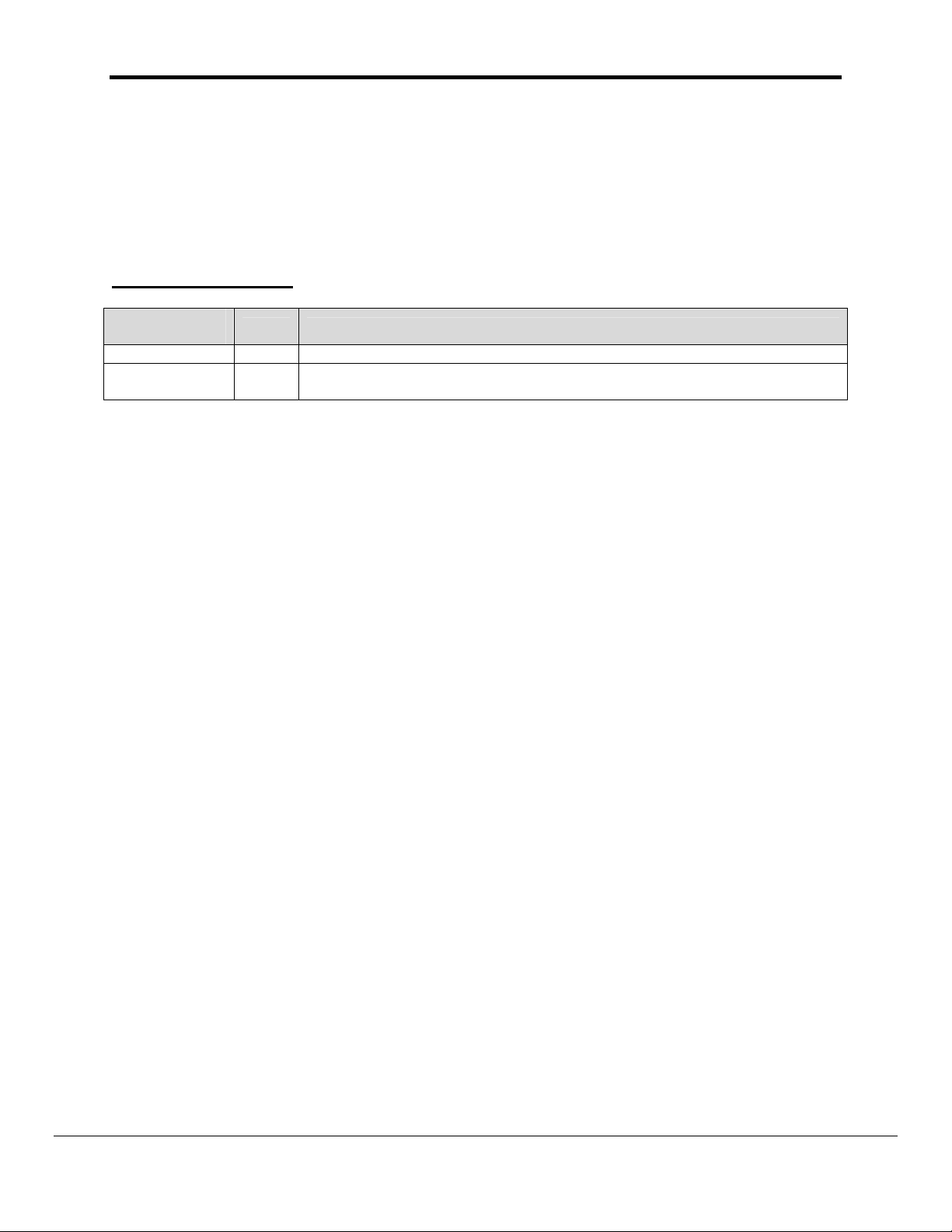
Max Nodes Supported
FieldServer
Mode
Client 1 The FieldServer can only emulate one DeviceNet Master station
Server 63
Nodes Comments
The driver can communicate with up to 63 Slaves as long as the FieldServer
point count license is not exceeded
FieldServer Technologies 1991 Tarob Court Milpitas, California 95035 USA Web: www.fieldserver.com
Tel: (408) 262 2299 Fax: (408) 262 2269 Toll Free: (888) 509 1970 email: support@fieldserver.com
Page 4

FS-8700-114 DeviceNet Master Manual Page 4 of 15
2. Driver Scope of Supply
2.1. Supplied by FieldServer Technologies for this driver
FieldServer Technologies PART # Description
FS-8700-114 Driver Manual.
X30-DeviceNet-Master Anybus-M DeviceNet Card
2.2. Provided by the Supplier of 3rd Party Equipment
2.2.1. Required 3rd Party Software
RSNetWorx, RSLogix or another Network Scheduling Tool.
2.2.2. Required 3rd Party Configuration
Connection to a properly terminated DeviceNet network.
2.2.3. Optional Items
PART # Vendor/Manufacturer Description
-
HMS-Networks Anybus-M DeviceNet eds file
FieldServer Technologies 1991 Tarob Court Milpitas, California 95035 USA Web: www.fieldserver.com
Tel: (408) 262 2299 Fax: (408) 262 2269 Toll Free: (888) 509 1970 email: support@fieldserver.com
Page 5
FS-8700-114 DeviceNet Master Manual Page 5 of 15
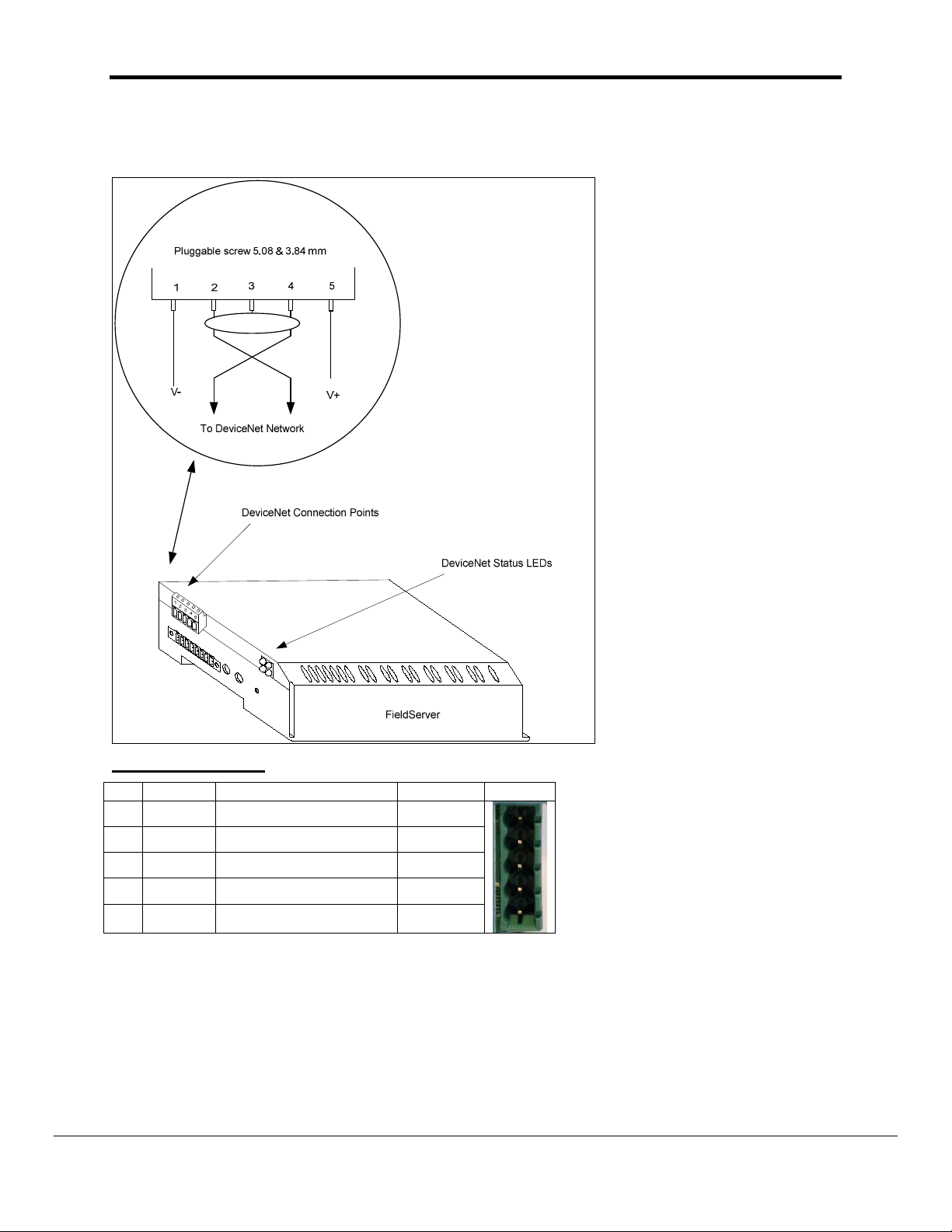
3. Hardware Connections
The FieldServer is connected to the DeviceNet network as shown in the connection drawing below.
Connector Pinouts
Pin Signal Description Wire color
1 V- Negative supply voltage black
2 CAN_L CAN_L Bus line blue
3 SHIELD Cable Shield (bare)
4 CAN_H CAN_H Bus line white
5 V+ Positive Supply Voltage red
3.1. Hardware Connection Tips / Hints
Use the recommended network cable and terminators as specified by the DeviceNet network
organization and/or the manufacturer of your network equipment.
Terminate each end of the DeviceNet network with a 121 Ω resistor
The bus interface shall be supplied with 24DC ± 10% on the Fieldbus connector
FieldServer Technologies 1991 Tarob Court Milpitas, California 95035 USA Web: www.fieldserver.com
Tel: (408) 262 2299 Fax: (408) 262 2269 Toll Free: (888) 509 1970 email: support@fieldserver.com
Page 6

FS-8700-114 DeviceNet Master Manual Page 6 of 15
4. Configuring the FieldServer as a DeviceNet Master
For a detailed discussion on FieldServer configuration, please refer to the FieldServer Configuration
Manual. The information that follows describes how to expand upon the factory defaults provided in the
configuration files included with the FieldServer (See “.csv” files provided with the FieldServer).
This section documents and describes the parameters necessary for configuring the FieldServer to
communicate with a DeviceNet Slave.
The configuration file tells the FieldServer about its interfaces, and the routing of data required. In order to
enable the FieldServer for DeviceNet communications, the driver independent FieldServer buffers need to
be declared in the “Data Arrays” section, the FieldServer virtual node(s) needs to be declared in the
“Server Side Nodes” section, and the data to be provided to the clients needs to be mapped in the
“Server Side Map Descriptors” section. Details on how to do this can be found below.
Note that in the tables, * indicates an optional parameter, with the bold legal value being the default.
4.1. DeviceNet Settings
Section Title
Bridge
Column Title Function Legal Values
System_Station_Address* DeviceNet MAC ID of the FieldServer
Note:
The DeviceNet MAC ID can also be set via the DIP switches on the side of the FieldServer but then
the system station address parameter must be removed from the configuration file.
Refer to Appendix B.1 for more information.
Example
// FieldServer
Bridge
Title, System_Station_Address
DeviceNet_Test, 5
0-63
FieldServer Technologies 1991 Tarob Court Milpitas, California 95035 USA Web: www.fieldserver.com
Tel: (408) 262 2299 Fax: (408) 262 2269 Toll Free: (888) 509 1970 email: support@fieldserver.com
Page 7

FS-8700-114 DeviceNet Master Manual Page 7 of 15
4.2. Client Side Connection Descriptors
Section Title
Connections
Column Title Function Legal Values
Adapter Adapter Name DNet
Protocol Protocol name X30_DNet_Master
DNet_Master_Baudrate1 Baudrate 125K , 250K , 500K
Command_DA_Name Commanding Scanner
Status_DA_Name Provide Scanner status
Example
// Server Side Connections
Connections
Adapter, Protocol, DNet_Master_Baudrate, Command_DA_Name, Status_DA_Name
DNet, X30_DNet_Master, 500K, Command_Reg, Status_Reg
Name of a data array declared
under Data Arrays section, length of
8 - Bit data array type recommended
4.3. Client Side Node Descriptors
Section Title
Nodes
Column Title Function Legal Values
Node_Name Provide name for node Up to 32 alphanumeric characters
Node_ID MAC ID of Slave to scan 0 - 63
Protocol Specify protocol used X30_DNet_Master
Example
// Server Side Nodes
Nodes
Node_Name, Node_ID, Protocol
DN1, 01, X30_DNet_Master
1
If System_Station_Address has not been defined in the CSV file, the DIP switch value for both MacID
and Baudrate will be used and the baud parameter in the CSV file will be ignored.
FieldServer Technologies 1991 Tarob Court Milpitas, California 95035 USA Web: www.fieldserver.com
Tel: (408) 262 2299 Fax: (408) 262 2269 Toll Free: (888) 509 1970 email: support@fieldserver.com
Page 8

FS-8700-114 DeviceNet Master Manual Page 8 of 15
4.4. Client Side Map Descriptors
4.4.1. FieldServer Specific Map Descriptor Parameters
Column Title Function Legal Values
Map_Descriptor_Name Name of this Map Descriptor
Data_Array_Name
Data_Array_Offset Starting location in Data Array
Function
Scan_Interval Buffers Update Period > 0.001s
Name of Data Array where data
is to be stored in the FieldServer
Function of Server Map
Descriptor
Up to 32 alphanumeric
characters
One of the Data Array names
from “Data Array” section above
0 to maximum specified in “Data
Array” section above
RDBC -Reads data from the
remote input buffer
WRBC -Writes data to the remote
output buffer
4.4.2. Driver Specific Map Descriptor Parameters
Column Title Function Legal Values
One of the Node names
Node_Name Name of Node
DeviceNet_Data_Type Data Type of remote buffer Byte, Word, Dword, Float, Bool
Address Byte offset into remote buffer
Length
Number of DeviceNet_Data_Type
items in remote buffer
specified in “Server Node
Descriptor” above
RDBC: 0 – 511
WRBC: 0 – 511
BYTE: 1 – 512
WORD: 1 – 256
DWORD: 1 – 128
FLOAT: 1 –128
BOOL: 1 – 4096
FieldServer Technologies 1991 Tarob Court Milpitas, California 95035 USA Web: www.fieldserver.com
Tel: (408) 262 2299 Fax: (408) 262 2269 Toll Free: (888) 509 1970 email: support@fieldserver.com
Page 9

Scan_Interval
Length,
Address,
Note that each address
refers to an individual
remote input and output
buffer. Each buffer can
contain up to 512 bytes.
DeviceNet_Data_Type,
Node_Name,
Write function map
descriptor puts
data from the
Output_Data data
array onto the
DeviceNet
network.
Data_Array_Offset, Function,
Data_Array_Name,
Tel: (408) 262 2299 Fax: (408) 262 2269 Toll Free: (888) 509 1970 email: support@fieldserver.com
FieldServer Technologies 1991 Tarob Court Milpitas, California 95035 USA Web: www.fieldserver.com
Read function map
descriptor gets data
from the DeviceNet
network and stores it
in the Input_Data
data array.
4.4.3. Map Descriptor Example.
FS-8700-114 DeviceNet Master Manual Page 9 of 15
// Client side Map Descriptors
Map_Descriptors
Map_Descriptor_Name,
Get_Data, Input_Data, 0, RDBC, CN1, WORD, 0, 10, 1s
Put_Data, Output_Data, 0. WRBC, CN1, WORD, 0, 10, 1s
Page 10

FS-8700-114 DeviceNet Master Manual Page 10 of 15
Appendix A. Advanced Topics
Appendix A.1. DeviceNet X30 LED indicators
LED 1 – Reserved
LED 2 – Network Status
Color Frequency Description
- Off No power, not initialized or no connections established
Green On Online, one or more connections established
Green Flashing Online, no connections established
Red On Critical link failure
Red Flashing Minor fault, one or more connections have a minor fault
LED 3 – Module Status
Color Frequency Description
- Off No power or not initialized
Green On Module status is OK
Red On Major fault
Red Flashing Minor fault
LED 4 – Operation Mode
Color Frequency Description
- Off No power or not initialized
Green Flashing Idle mode
Green On Run mode
FieldServer Technologies 1991 Tarob Court Milpitas, California 95035 USA Web: www.fieldserver.com
Tel: (408) 262 2299 Fax: (408) 262 2269 Toll Free: (888) 509 1970 email: support@fieldserver.com
Page 11

FS-8700-114 DeviceNet Master Manual Page 11 of 15
Appendix A.2. Using RSNetWorx
Please refer to the following document on the HMS website, www.anybus.com
ANYBUS-M DEVICENET MASTER/SCANNER APPENDIX Revision 1.02 - Section 5.3
“Configuration with RSNetworx”.
FieldServer Technologies 1991 Tarob Court Milpitas, California 95035 USA Web: www.fieldserver.com
Tel: (408) 262 2299 Fax: (408) 262 2269 Toll Free: (888) 509 1970 email: support@fieldserver.com
Page 12

FS-8700-114 DeviceNet Master Manual Page 12 of 15
Appendix B. Driver Notes
Appendix B.1. Setting the FieldServer’s DeviceNet MAC ID and Baudrate
The MAC ID and Baudrate can be set in the FieldServer’s CSV file using the
System_Station_Address and DNet_Master_Baudrate parameters or it can be set with DIP switches
as depicted below.
Note:
The System_Station_Address parameter must be removed from the configuration file if the DIP
switch setting is to be used.
If System_Station_Address has not been defined in the CSV file, the DIP switch value for both MacID
and Baudrate will be used and the baud parameter in the CSV file will be ignored.
Appendix B.2. Using the Command and Status Data Arrays
The Command Data Array controls the Scanner’s mode which can be either Run or Idle. The Scanner
can only be configured when in Idle mode. A non-zero value at offset zero in the Command Data
Array will place the Scanner in Run mode; a value of zero will place it in Idle mode. The Scanner
FieldServer Technologies 1991 Tarob Court Milpitas, California 95035 USA Web: www.fieldserver.com
Tel: (408) 262 2299 Fax: (408) 262 2269 Toll Free: (888) 509 1970 email: support@fieldserver.com
Page 13

FS-8700-114 DeviceNet Master Manual Page 13 of 15
always powers up in Idle mode and can be set to Run mode automatically with a preload section or
from the Server side protocol of the FieldServer. The following preload section can be placed in the
configuration file to place the scanner in Run mode at power-up:
Preloads
Data_Array_Name, Preload_Data_Format, Preload_Data_Value, Location
Command_Reg, Bit, 1, 0
Offset zero of the Status Data Array indicates the Scanner’s actual mode achieved. A non-zero value
indicates the Scanner is in Run mode and a value of zero indicates the scanner is in Idle mode.
Appendix B.3. Master Status Codes
The Master Status codes displayed on the F-screen are depicted below:
FieldServer Technologies 1991 Tarob Court Milpitas, California 95035 USA Web: www.fieldserver.com
Tel: (408) 262 2299 Fax: (408) 262 2269 Toll Free: (888) 509 1970 email: support@fieldserver.com
Page 14

FS-8700-114 DeviceNet Master Manual Page 14 of 15
Example:
If the Master reports a network failure the following screenshot will be displayed:
FieldServer Technologies 1991 Tarob Court Milpitas, California 95035 USA Web: www.fieldserver.com
Tel: (408) 262 2299 Fax: (408) 262 2269 Toll Free: (888) 509 1970 email: support@fieldserver.com
Page 15

FS-8700-114 DeviceNet Master Manual Page 15 of 15
Appendix B.4. Understanding buffer types and Map Descriptor functions
The diagram below explains the data flows for both buffers when using the FieldServer as a DN
Master:
Note that for the Input buffer, the data is coming from the external DN Slave and is transferred into
the DN Master card’s internal input buffer. The Rdbc (Read Data Block Continuous) Map Descriptor
transfers the data from the card buffer into the FieldServer’s Data Array packing it correctly according
to the specified DeviceNet_Data_Type.
For the Output buffer, the data is written from the FieldServer’s Data Array by the WRBC function
Map Descriptor (Write Data Block Continuous) into the DN Master card’s internal output buffer from
where it is transferred across the DeviceNet network to the external DN Slave’s input buffer.
FieldServer
Data Array
WRBC Map Descriptor
Note: The Node_Name determines to
which external DN Slave date will be
sent to or fetched from.
Data Array
RDBC Map Descriptor
DeviceNet Card
Card input buffer
0 1
Card output buffer
0
1
….
….
DN Master
243
243
DeviceNet
Network
External DN Slave 01
Card output buffer
0
1
….
Card input buffer
0 1
Card output buffer
0
Card input buffer
0 1
….
External DN Slave 126
1
….
….
243
243
243
243
Appendix B.5.
The DeviceNet driver only supports IO data. To access parameter data on Slaves it is necessary to
refer to the Slave device's user manuals for information on how to map their parameter data to IO
data locations.
FieldServer Technologies 1991 Tarob Court Milpitas, California 95035 USA Web: www.fieldserver.com
Tel: (408) 262 2299 Fax: (408) 262 2269 Toll Free: (888) 509 1970 email: support@fieldserver.com
Accessing Parameter Data in Remote Slaves
 Loading...