

Page 1

-
A Sierra Monitor Company
Driver Manual
(Supplement to the FieldServer Instruction Manual)
FS-8700-101
Setra Digital Pressure Gage Model 370
APPLICABILITY & EFFECTIVITY
Effective for all systems manufactured after May 1, 2001
Driver Version: 1.00
Document Revision: 7
Page 2

FS-8700-101 Setra Model 370 Digital Pressure Gage Manual Table of Contents
TABLE OF CONTENTS
1. SETRA MODEL 370 DIGITAL PRESSURE GAGE DESCRIPTION.................................3
2. DRIVER SCOPE OF SUPPLY...........................................................................................4
2.1. Supplied by FieldServer Technologies for this driver ...................................................4
2.2. Provided by the Supplier of 3rd Party Equipment.......................................................... 4
2.2.1. Required 3rd Party Hardware.....................................................................................4
2.2.2. Required 3rd Party Configuration...............................................................................4
3. HARDWARE CONNECTIONS ..........................................................................................5
3.1. Hardware Connection Tips / Hints................................................................................6
4. CONFIGURING THE FIELDSERVER AS A SETRA MODEL 370 DIGITAL PRESSURE
GAGE CLIENT .............................................................................................................................7
4.1. Data Arrays/Descriptors ...............................................................................................7
4.2. Client Side Connection Descriptors.............................................................................. 8
4.3. Client Side Node Descriptors .......................................................................................8
4.4. Client Side Map Descriptors .........................................................................................9
4.4.1. FieldServer Related Map Descriptor Parameters......................................................9
4.4.2. Driver Related Map Descriptor Parameters ..............................................................9
4.4.3. Timing Parameters....................................................................................................9
4.4.4. Map Descriptor Example #1 – Read Pressure........................................................10
4.4.5. Map Descriptor Example #2 – Read Status............................................................11
4.4.6. Map Descriptor Example #3 - Verify........................................................................12
5. CONFIGURING THE FIELDSERVER AS A SETRA MODEL 370 DIGITAL PRESSURE
GAGE SERVER..........................................................................................................................13
5.1. Server Side Connection Descriptors...........................................................................13
5.2. Server Side Node Descriptors ....................................................................................14
5.3. Server Side Map Descriptors...................................................................................... 15
5.3.1. FieldServer Specific Map Descriptor Parameters ...................................................15
5.3.2. Driver Specific Map Descriptor Parameters............................................................15
5.3.3. Server Map Descriptor Example. ............................................................................16
APPENDIX A. ADVANCED TOPICS ......................................................................................17
Appendix A.1. How Data Gets Stored ..................................................................................17
Appendix A.1.1. Pressure Data.........................................................................................17
Appendix A.1.2. Status Data.............................................................................................17
Appendix A.2. Gage Pressure Units ..................................................................................... 18
Appendix A.3. Driver Limitations & Exclusions ..................................................................... 18
APPENDIX B. TROUBLESHOOTING TIPS............................................................................19
Appendix B.1. Connection Tips & Hints................................................................................19
APPENDIX C. DRIVER ERROR MESSAGES........................................................................20
Appendix C.1. Exposing Driver Diagnostic Statistics............................................................21
Appendix C.2. Standard Driver Stats....................................................................................22
FieldServer Technologies 1991 Tarob Court Milpitas, California 95035 USA Web:www.fieldServer.com
Tel: (408) 262-2299 Fax: (408) 262-9042 Toll_Free: 888-509-1970 email: support@fieldServer.com
Page 3
FS-8700-101_Setra Model 370 Digital Pressure Gage Manual Page 3 of 23
1. Setra Model 370 Digital Pressure Gage Description
The ‘Setra Model 370 Digital Pressure Gage’ driver allows the FieldServer to transfer data to
and from devices over either RS-232 or RS-485 using the ‘Setra Model 370 Digital Pressure
Gage’ protocol. The FieldServer can emulate either a Server or Client.
The driver implements a subset of the commands and responses that an actual Setra Model
370 Digital Pressure Gage is capable of. Thus the driver permits the transfer of current pressure
information, Gage status information and the processing of Gage verification information.
The driver is capable of providing active Client and passive Server support. An active Client
polls for data and processes responses, it is not capable of processing unsolicited messages
from the remote device. A passive Server can respond to polls but is not capable of sending
unsolicited messages reporting change of state or other information.
When configured as a Client it is important the digital Gage is configured correctly and that it is
left in an operational mode where it can respond easily to the commands sent to it. If a user,
were to operate the Gage from its front panel and leave it in a configuration state, awaiting input
from a user, then the Gage would be incapable of responding to commands from the
FieldServer. The driver cannot write to the digital Gage. Thus alarm set points and other
configuration tasks cannot be performed using a FieldServer.
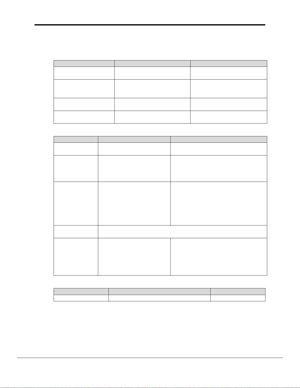
Max Nodes Supported
FieldServer
Mode
Client 1
Nodes Comments
This is a nodeless protocol. Only one Server per FieldServer
port.
Server 1 This is a nodeless protocol. Only one Client per FieldServer port.
FieldServer Technologies 1991 Tarob Court Milpitas, California 95035 USA Web:www.fieldServer.com
Tel: (408) 262-2299 Fax: (408) 262-9042 Toll_Free: 888-509-1970 email: support@fieldServer.com
Page 4
FS-8700-101_Setra Model 370 Digital Pressure Gage Manual Page 4 of 23
2. Driver Scope of Supply
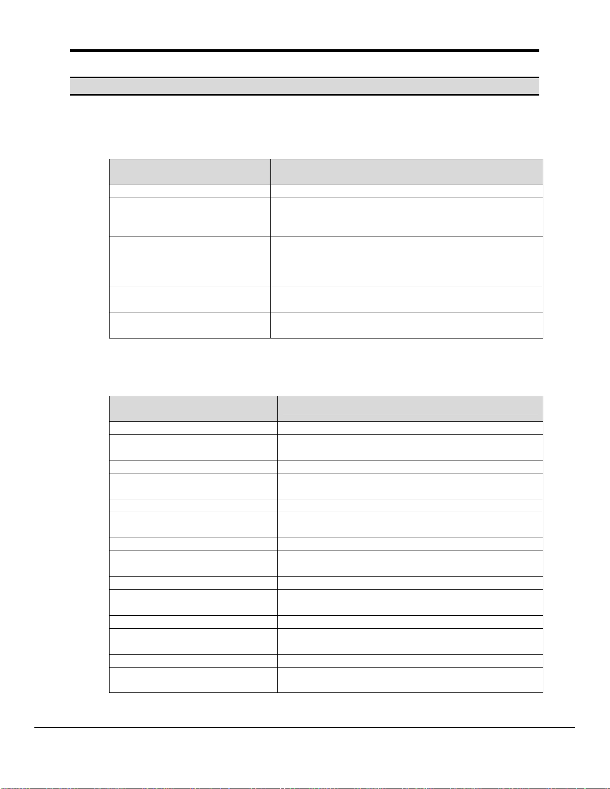
2.1. Supplied by FieldServer Technologies for this driver
FieldServer Technologies
PART #
Description
FS-8917-01 Connector, 25 pin male: Connects to DCE, RTS/CTS loop
FS-8700-101 Driver Manual.
2.2. Provided by the Supplier of 3rd Party Equipment
2.2.1. Required 3rd Party Hardware
Part # Description
M370 SETRA DIGITAL PRESSURE GAGE
2.2.2. Required 3rd Party Configuration
The M370 Gage must be configured using the operator’s manual and the front panel
push buttons so that its serial port settings match the FieldServer settings.
The following notes have been extracted from the operator’s manual.
The Setra Digital Pressure Gage is capable of interfacing with a wide variety of computers or
other devices through the RS-232 serial communications port. Devices which are connected this
way must be set up to communicate at the same rate of speed. To change the baud rate of the
gage (the rate at which the gage sends information out through the port) so it agrees with that of
the device connected to it, use the following procedure.
1. Press CONV until the gage is displaying pressure units (make sure it is not displaying in "ft" or
"meters").
2. Press the "-" key.
3. Enter "5555". This is the baud rate access code.
4. Press SETUP. The display will read "CAL br".
5. Enter the baud rate. Choose either 300, 600, 1200, 1800, 2400, 3600, 4800or 9600.
6. Press SETUP.
The baud rate is factory set to 2400. If you change the baud rate and wish the gage to retain the
new rate after power is removed and restored, repeat steps 2-6 a second time.
FieldServer Technologies 1991 Tarob Court Milpitas, California 95035 USA Web:www.fieldServer.com
Tel: (408) 262-2299 Fax: (408) 262-9042 Toll_Free: 888-509-1970 email: support@fieldServer.com
Page 5
FS-8700-101_Setra Model 370 Digital Pressure Gage Manual Page 5 of 23
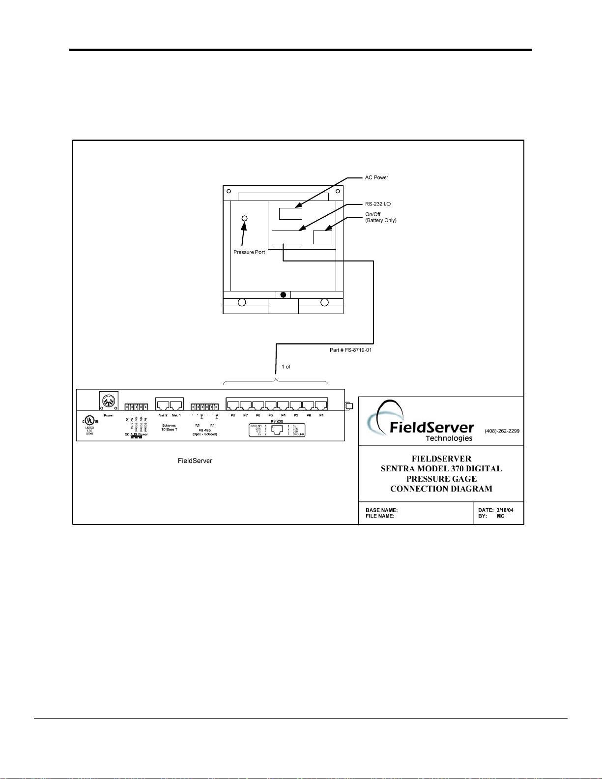
3. Hardware Connections
The FieldServer is connected to the rear side of the Model 370 Digital Pressure Gage as shown
in the following connection drawing.
FieldServer Technologies 1991 Tarob Court Milpitas, California 95035 USA Web:www.fieldServer.com
Tel: (408) 262-2299 Fax: (408) 262-9042 Toll_Free: 888-509-1970 email: support@fieldServer.com
Page 6

FS-8700-101_Setra Model 370 Digital Pressure Gage Manual Page 6 of 23
3.1. Hardware Connection Tips / Hints
The following notes are extracted from the Setra 370 Operator Manual.
The Setra Digital Pressure Gage implements the majority of the RS-232 communications standard,
but does not provide handshaking lines (such as busy, DSR, or DTR). The four lines which must be
connected are diagrammed below, along with the pin layout of the female connector on the back of
the gage.
13 7 3 2 1
O O O O O O O O O O O O O
O O O O O O O O O O O O
25 14
Pin Desc.
1 Protective ground
2 Input to gage (RXD)
3 Output from gage (TXD)
7 Signal ground
The Model 370 serial interface is a DCE (Data Communications Equipment) type, with a standard
female DB25S pin connector. This means that it receives data on pin 2 and sends data on pin 3. This
is in contrast to DTE (Data Transmission Equipment) which receives data on pin 3 and sends data on
pin 2. The RS-232 standard describes communications between DTE and DCE devices.
Since many computers have serial ports configured as DTE, the Model 370 conveniently plugs
directly into the standard serial port on most computers, using a standard RS-232 "straight-through"
cable available from SETRA, or from any computer hardware vendor. Some devices, including some
printers and computers, will be equipped with DCE interfaces like that in the Model 370. To connect
the Model 370 to these devices, a "null modem" cable is required. This is simply a cable which
connects pin 2 and 3 of the Model 370 to pin 3 and 2 of the other device respectively by crossing
them in the cable. This kind of cable is also available from SETRA, or from any computer hardware
vendor.
The maximum recommended cable length is 15 meters.
The RS-232 data format used by the Model 370 is:
8 bits, 1 start bit, 1 stop bit, no parity.
FieldServer Technologies 1991 Tarob Court Milpitas, California 95035 USA Web:www.fieldServer.com
Tel: (408) 262-2299 Fax: (408) 262-9042 Toll_Free: 888-509-1970 email: support@fieldServer.com
Page 7
FS-8700-101_Setra Model 370 Digital Pressure Gage Manual Page 7 of 23
4. Configuring the FieldServer as a Setra Model 370 Digital Pressure Gage
Client
For a detailed discussion on FieldServer configuration, please refer to the FieldServer
Configuration Manual. The information that follows describes how to expand upon the factory
defaults provided in the configuration files included with the FieldServer (See “.csv” sample files
provided with the FieldServer).
This section documents and describes the parameters necessary for configuring the FieldServer
to communicate with a Setra Model 370 Digital Pressure Gage.
4.1. Data Arrays/Descriptors
The configuration file tells the FieldServer about its interfaces, and the routing of data
required. In order to enable the FieldServer for Setra Model 370 Digital Pressure Gage
communications, the driver independent FieldServer buffers need to be declared in the
“Data Arrays” section, the destination device addresses need to be declared in the “Client
Side Nodes” section, and the data required from the Servers needs to be mapped in the
“Client Side Map Descriptors” section. Details on how to do this can be found below.
Note that in the tables, * indicates an optional parameter, with the bold legal value being the
default.
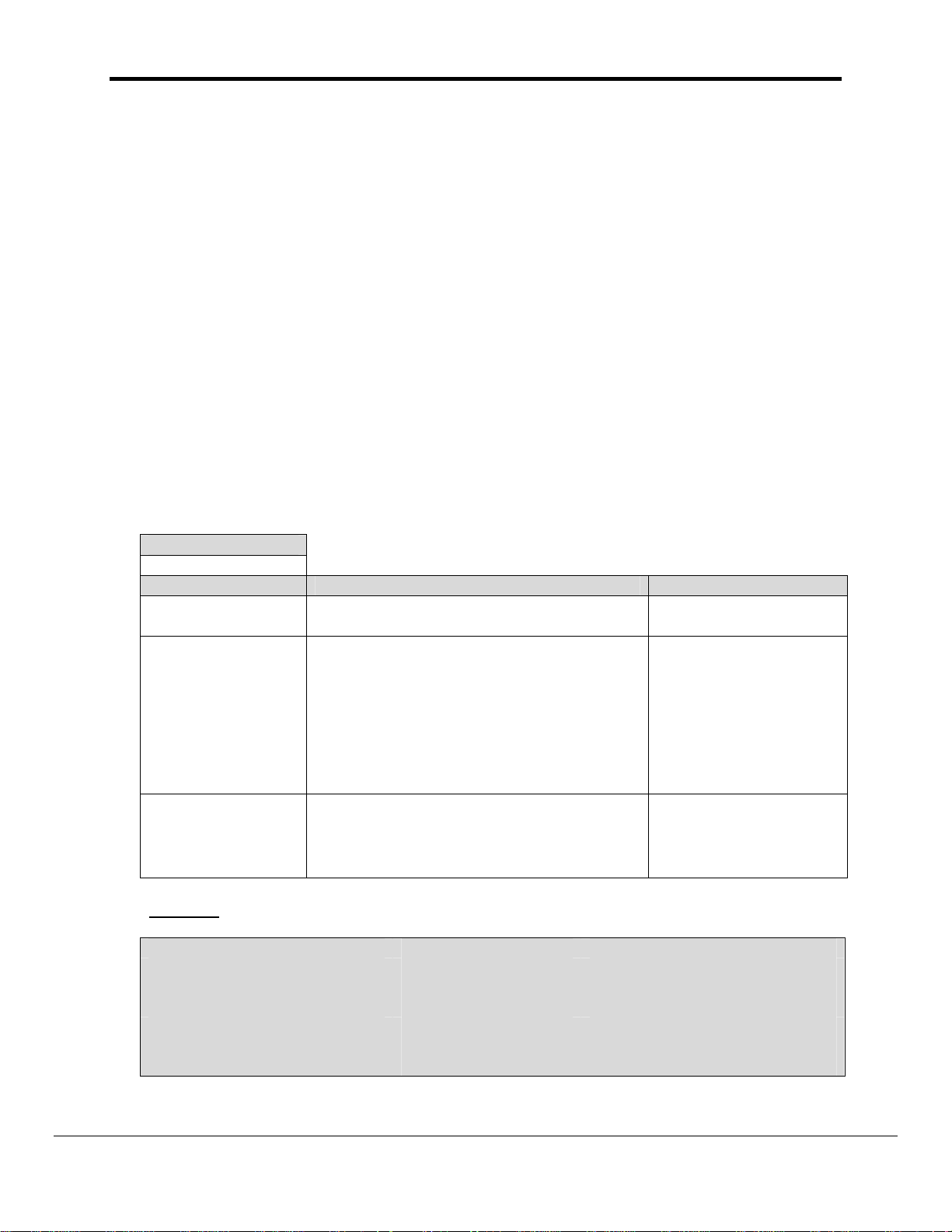
Section Title
Data_Arrays
Column Title Function Legal Values
Data_Array_Name Provide name for Data Array
Provide data format. Each Data Array can
only take on one format.
For this driver, FieldServer recommends
Data_Array_Format
Data_Array_Length
Example
// Data Arrays
Data_Arrays
Data_Array_Name, Data_Format, Data_Array_Length,
DA_PRESSURE, FLOAT, 200
DA_STATUS, FLOAT, 200
DA_DI_01, Bit, 200
DA_DO_01, Bit, 200
the use of a FLOAT Data Array. This is
because the pressure and status settings
are reported as real signed numbers with
some significant digits after the decimal
point.
Number of Data Objects. Must be larger
than the data storage area required by the
Map Descriptors for the data being placed
in this array.
Up to 15 alphanumeric
characters
Float, Bit, UInt16,
SInt16, Packed_Bit,
Byte, Packed_Byte,
Swapped_Byte
1-10,000
FieldServer Technologies 1991 Tarob Court Milpitas, California 95035 USA Web:www.fieldServer.com
Tel: (408) 262-2299 Fax: (408) 262-9042 Toll_Free: 888-509-1970 email: support@fieldServer.com
Page 8

FS-8700-101_Setra Model 370 Digital Pressure Gage Manual Page 8 of 23
4.2. Client Side Connection Descriptors
Section Title
Connections
Column Title Function Legal Values
Port
Protocol Specify protocol used Setra370
Baud* Specify baud rate
Parity* Specify parity Even, Odd, None, Mark, Space
Data_Bits* Specify data bits 7, 8
Stop_Bits* Specify stop bits
Handshaking*
Poll _Delay* Time between internal polls 0-32000 seconds, 1 second
Example
// Client Side Connections
Connections
Port, Protocol, Baud, Parity, Handshaking, Poll_Delay
P8, Setra370, 2400, None, None, 0.100s
Specify which port the device is
connected to the FieldServer
Specify hardware handshaking
The Setra Model 370 does not support
handshaking.
P1-P8, R1-R21
110 – 115200, standard baud
rates only, 2400.
1
RTS, RTS/CTS, None
4.3. Client Side Node Descriptors
Section Title
Nodes
Column Title Function Legal Values
Node_Name Provide name for node
Node_ID
This commonly used parameter has no meaning for this driver and may be
omitted.
Protocol Specify protocol used Setra370.
Connection
Specify which port the device is connected
to the FieldServer
Example
// Client Side Nodes
Nodes
Node_Name, Protocol, Connection
Gage1, Setra370, P8
1
Not all ports shown are necessarily supported by the hardware. Consult the appropriate Instruction
manual for details of the ports available on specific hardware.
Up to 32 alphanumeric
characters
P1-P8, R1-R21
FieldServer Technologies 1991 Tarob Court Milpitas, California 95035 USA Web:www.fieldServer.com
Tel: (408) 262-2299 Fax: (408) 262-9042 Toll_Free: 888-509-1970 email: support@fieldServer.com
Page 9
FS-8700-101_Setra Model 370 Digital Pressure Gage Manual Page 9 of 23
4.4. Client Side Map Descriptors
4.4.1. FieldServer Related Map Descriptor Parameters
Column Title Function Legal Values
Map_Descriptor_Name Name of this Map Descriptor
Name of Data Array where
Data_Array_Name
Data_Array_Offset
Function
data is to be stored in the
FieldServer
Starting location in Data
Array
Function of Client Map
Descriptor
Up to 32 alphanumeric
characters
One of the Data Array names
from “Data Array” section
above
0 to maximum specified in
“Data Array” section above
RDBC
4.4.2. Driver Related Map Descriptor Parameters
Column Title Function Legal Values
Node_Name
Data_Type
Length Length of Map Descriptor
Address
Gage_Function*
Name of Node to fetch data
from
This commonly used
parameter has no special
meaning to this driver and
may be omitted.
This commonly used parameter has no special meaning to this
driver and may be omitted.
Specifies what data should
be read and stored.
If you omit this parameter
then the driver assumes
you are reading pressure.
One of the node names specified in
“Client Node Descriptor” above
Register, Coil, AI, DI
The driver knows the correct length
for the various Map Descriptors and
will prompt you accordingly if an
invalid length is specified.
Pressure : Set Length 5
Status: Set Length 14
Verification Info: Set length 100.
Pressure, Status, Verify
4.4.3. Timing Parameters
Column Title Function Legal Values
Scan_Interval Rate at which data is polled ≥0.001s
FieldServer Technologies 1991 Tarob Court Milpitas, California 95035 USA Web:www.fieldServer.com
Tel: (408) 262-2299 Fax: (408) 262-9042 Toll_Free: 888-509-1970 email: support@fieldServer.com
Page 10

FS-8700-101_Setra Model 370 Digital Pressure Gage Manual Page 10 of 23
t
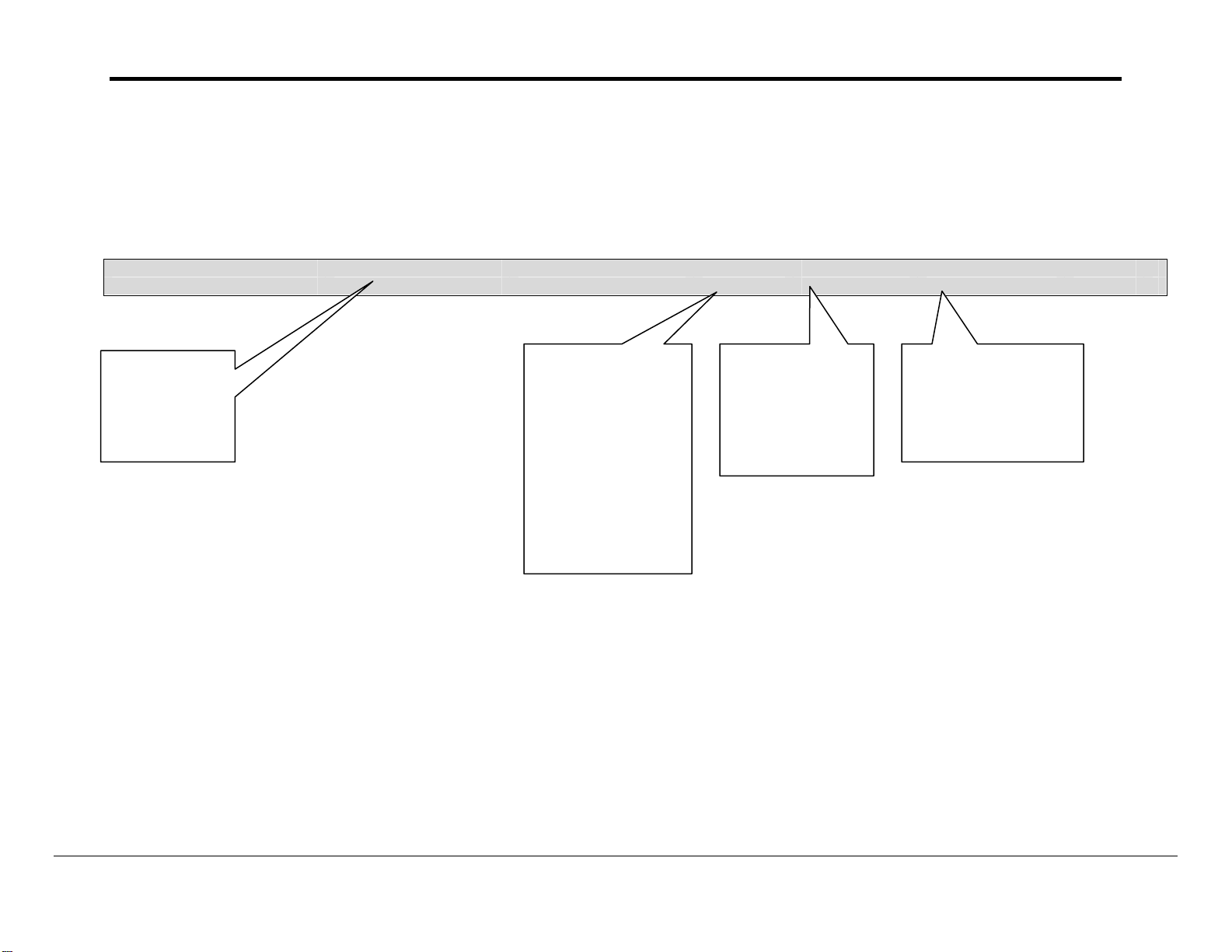
4.4.4. Map Descriptor Example #1 – Read Pressure.
In this example a Map Descriptor is defined which controls the task of reading pressure data from the Setra Model 370 Digital
Pressure Gage. The task gets performed every 5.0 seconds. When a response is received the data is stored in the Data Array
called DA_PRESSURE stating at element zero (the offset). Each pressure reading requires the driver store 5 parameters and hence
the length of the Map Descriptor is 5. Refer to Appendix A for further information.
Map_Descriptor_Name, Data_Array_Name, Data_Array_Offset, Function, Node_Name, Gage_Function, Length, Scan_Interval
Read_Press, DA_PRESSURE, 0, RDBC, Gage1, Pressure, 5, 5.0s
Unique names
assist config file
validation
debugging but
are not
necessary.
The name of a
Data Array in
which the
response data
will be stored
s
The 1
in the Data
Array which will
be used for
.
storage.
location
The name of a Node
defined in the CSV file.
The node name connect
the MD to a node which
in turn points to a
connection Thus the
driver knows what port
and port settings to use
to send the poll..
Tells the driver
to read the
current
pressure
measurement
from the Gage
Reserves 5
elements of the
Data Array to
store response
data.
Tells the driver
to schedule this
MD no more
often than 5
seconds.
FieldServer Technologies 1991 Tarob Court Milpitas, California 95035 USA Web:www.fieldServer.com
Tel: (408) 262-2299 Fax: (408) 262-9042 Toll_Free: 888-509-1970 email: support@fieldServer.com
Page 11

FS-8700-101_Setra Model 370 Digital Pressure Gage Manual Page 11 of 23
t
4.4.5. Map Descriptor Example #2 – Read Status
In this example a Map Descriptor is defined which controls the task of reading status data from the Setra Model 370 Digital Pressure
Gage. The task gets performed every 5.0 seconds. When a response is received the data is stored in the Data Array called
DA_STATUS stating at element zero (the offset). Each pressure status reading requires the driver store 20 parameters and hence
the length of the Map Descriptor is 20. Refer to Appendix A for further information.
Map_Descriptor_Name, Data_Array_Name, Data_Array_Offset, Function, Node_Name, Gage_Function, Length, Scan_Interval
Read_Status, DA_STATUS, 0, RDBC, Gage1, Status , 20, 5.0s
Unique names
assist config file
validation
debugging but
are not
necessary
.
The name of a
Data Array in
which the
response data
will be stored.
s
The 1
in the Data
Array which will
be used for
storage.
location
The name of a Node defined in
the CSV file. The node name
connect the MD to a node which
in turn points to a connection
Thus the driver knows what port
and port settings to use to send
the poll..
Tells the driver
to read the
current status
from the Gage
Reserves 20
elements of the
Data Array to
store response
data.
Tells the driver
to schedule this
MD no more
often than 5
seconds.
FieldServer Technologies 1991 Tarob Court Milpitas, California 95035 USA Web:www.fieldServer.com
Tel: (408) 262-2299 Fax: (408) 262-9042 Toll_Free: 888-509-1970 email: support@fieldServer.com
Page 12

FS-8700-101_Setra Model 370 Digital Pressure Gage Manual Page 12 of 23
t
4.4.6. Map Descriptor Example #3 - Verify.
The verification string contains revision and model information about the Gage. In this example a Map Descriptor is defined which
controls the task of reading verification data from the Setra Model 370 Digital Pressure Gage. The task gets performed every 5.0
seconds. When a response is received the data is stored in the Data Array called DA_VERIFY stating at element zero (the offset).
Each Gage verification reading requires the driver store a string containing two lines of data. The actual length is unknown in
advance and it is recommended that 100 Data Array elements be reserved to store the verification sting. The verification string is
stored by writing each consecutive letter in consecutive Data Array elements. It is recommended that the Data_Array_Format is set
to BYTE in this case. This will enable the use of the “String” display to read the verification string in RuiNet.
Map_Descriptor_Name, Data_Array_Name, Data_Array_Offset, Function, Node_Name, Gage_Function, Length, Scan_Interval
Read_Verify, DA_VERIFY, 0, RDBC, Gage1, Verify, 100, 5.0s
Unique names
assist config file
validation
debugging but
are not
The name of a
Data Array in
which the
response data
will be stored.
s
The 1
in the Data
Array which will
be used for
storage.
location
The name of a Node defined in
the CSV file. The node name
connect the MD to a node
which in turn points to a
connection Thus the driver
knows what port and port
settings to use to send the
poll..
Tells the driver
to read the
verification
string
measurement
from the Gage
Tells the driver
to schedule this
MD no more
often than 5
seconds.
Reserves 100
elements of the
Data Array to
store response
data.
FieldServer Technologies 1991 Tarob Court Milpitas, California 95035 USA Web:www.fieldServer.com
Tel: (408) 262-2299 Fax: (408) 262-9042 Toll_Free: 888-509-1970 email: support@fieldServer.com
Page 13

FS-8700-101_Setra Model 370 Digital Pressure Gage Manual Page 13 of 23
5. Configuring the FieldServer as a Setra Model 370 Digital Pressure Gage
Server
For a detailed discussion on FieldServer configuration, please refer to the FieldServer
Configuration Manual. The information that follows describes how to expand upon the factory
defaults provided in the configuration files included with the FieldServer.
This section documents and describes the parameters necessary for configuring the FieldServer
to communicate with a Setra Model 370 Digital Pressure Gage Client
The configuration file tells the FieldServer about its interfaces, and the routing of data required.
In order to enable the FieldServer for Setra Model 370 Digital Pressure Gage communications,
the driver independent FieldServer buffers need to be declared in the “Data Arrays” section, the
FieldServer virtual node(s) needs to be declared in the “Server Side Nodes” section, and the
data to be provided to the Clients needs to be mapped in the “Server Side Map Descriptors”
section. Details on how to do this can be found below.
Note that in the tables, * indicates an optional parameter, with the bold legal value being the
default.
5.1. Server Side Connection Descriptors
Section Title
Connections
Column Title Function Legal Values
Port
Protocol
Specify which port the device is
connected to the FieldServer
Specify protocol used Setra370
Baud* Specify baud rate
Parity* Specify parity
Data_Bits*
Stop_Bits*
Specify data bits 7, 8
Specify stop bits
P1-P8, R1-R2
110 – 115200, standard
baud rates only
Even, Odd, None, Mark,
Space
1
2
Handshaking* Specify hardware handshaking RTS, RTS/CTS, None
Specifies time FieldServer will
reserve Server side connection
Server_Hold_Timeout*
while waiting for the Client side to
>1.0s
update data in Data_Array (if
necessary)
Example
// Server Side Connections
Connections
Port, Protocol, Baud, Parity, Handshaking,
P8, Setra370, 9600, None, None,
2
Not all ports shown are necessarily supported by the hardware. Consult the appropriate Instruction
manual for details of the ports available on specific hardware.
FieldServer Technologies 1991 Tarob Court Milpitas, California 95035 USA Web:www.fieldServer.com
Tel: (408) 262-2299 Fax: (408) 262-9042 Toll_Free: 888-509-1970 email: support@fieldServer.com
Page 14

FS-8700-101_Setra Model 370 Digital Pressure Gage Manual Page 14 of 23
5.2. Server Side Node Descriptors
Section Title
Nodes
Column Title Function Legal Values
Node_Name Provide name for node
Node_ID
This commonly used parameter is not used by this driver and
maybe omitted.
Protocol Specify protocol used Setra370
Specifies time FieldServer will
reserve Server side connection
Server_Hold_Timeout*
while waiting for the Client side
to update data in Data_Array (if
necessary)
Example
// Server Side Nodes
Nodes
Node_Name, Protocol
∗
PLC 1, Setra370
Up to 32 alphanumeric
characters
>1.0s
∗
Note that no connection information is necessary on Server side.
FieldServer Technologies 1991 Tarob Court Milpitas, California 95035 USA Web:www.fieldServer.com
Tel: (408) 262-2299 Fax: (408) 262-9042 Toll_Free: 888-509-1970 email: support@fieldServer.com
Page 15

FS-8700-101_Setra Model 370 Digital Pressure Gage Manual Page 15 of 23
5.3. Server Side Map Descriptors
5.3.1. FieldServer Specific Map Descriptor Parameters
Column Title Function Legal Values
Map_Descriptor_Name
Data_Array_Name
Data_Array_Offset
Function
Server_Hold_Timeout*
Name of this Map
Descriptor
Name of Data Array where
data is to be stored in the
FieldServer
Starting location in Data
Array
Function of Server Map
Descriptor
Specifies time FieldServer
will reserve Server side
connection while waiting for
the Client side to update
data in Data_Array (if
necessary)
Up to 32 alphanumeric
characters
One of the Data Array
names from “Data Array”
section above
0 to maximum specified in
“Data Array” section above
Server
>1.0s
5.3.2. Driver Specific Map Descriptor Parameters
Column Title Function Legal Values
Node_Name
Data_Type
Length Length of Map Descriptor 1 - 1000
Address
Name of Node to fetch data
from
This commonly used
parameter has no special
meaning to this driver and
may be omitted.
This commonly used parameter has no special meaning to
this driver and may be omitted.
One of the node names
specified in “Client Node
Descriptor” above
Register, Coil, AI, DI
FieldServer Technologies 1991 Tarob Court Milpitas, California 95035 USA Web:www.fieldServer.com
Tel: (408) 262-2299 Fax: (408) 262-9042 Toll_Free: 888-509-1970 email: support@fieldServer.com
Page 16
FS-8700-101_Setra Model 370 Digital Pressure Gage Manual Page 16 of 23
p
5.3.3. Server Map Descriptor Example.
This Map Descriptor defines a capability of the FieldServer to respond to a poll for an immediate Pressure Print (Command Code =
‘P’). When the poll is received, the driver inspects 5 consecutive array elements starting at offset 0 in the Data Array named
DA_PRESSURE. The contents of the 5 elements are defined in Appendix A.1.1. The 2
pressure indicating letter. Both of these elements must be set to non-zero values.
Map_Descriptor_Name, Data_Array_Name, Data_Array_Offset, Function, Node_name Gage_Functon Length
SRV_Pressure, DA_PRESSURE 0, Server Gage1 Pressure, 5
nd
element is the units index, the 3rd is the
Data for the
response to a
‘P’ poll is
extracted from
this Data Array.
This function defines
a capability of the
FieldServer to
respond to an
incoming poll.
The Map Descriptor
is passive. It does
not generate
messages but is
used to respond.
The Node Name
must be the same
as one of the
nodes defined in
the ‘nodes’ section
of the CSV file.
Defines the capability
of this Map Descriptor.
This Map Descriptor
can only be used to
form responses to a
‘P’
oll.
FieldServer Technologies 1991 Tarob Court Milpitas, California 95035 USA Web:www.fieldServer.com
Tel: (408) 262-2299 Fax: (408) 262-9042 Toll_Free: 888-509-1970 email: support@fieldServer.com
Page 17
FS-8700-101_Setra Model 370 Digital Pressure Gage Manual Page 17 of 23
Appendix A. Advanced Topics
Appendix A.1. How Data Gets Stored
Appendix A.1.1. Pressure Data
Offset (where x is the offset
specified in the MD)
X + 0 Gage Pressure. A signed real number.
X + 1
X + 2
X + 3
X + 4
Notes
Gage Pressure Units. A whole number which is used
as a lookup into the table provide in section
“Appendix A.2 Gage Pressure Units”
Gage Pressure Indicating Letter
‘A’ = 65
‘G’ = 71
‘T’ = 84
Set to 1 If the pressure reading reports the status as
‘OK’
Set to 1 If the pressure reading reports the pressure
as a ‘SEA LEVEL’ reading
Appendix A.1.2. Status Data
If any fields are absent in the response to a poll for status data then the values are set to
zero for that field.
Offset (where x is the offset
specified in the MD)
X + 0 ‘ELEV:’ measurement. A signed real number.
X + 1
X + 2 ‘MAX:’ measurement. A signed real number.
X + 3
X + 4 ‘MIN:’ measurement. A signed real number.
X + 5
X + 6 ‘HI ALARM:’ measurement. A signed real number.
X + 7
X + 8 ‘LO ALARM:’ measurement. A signed real number.
X + 9
X + 10 ‘ZERO:’ measurement. A signed real number.
X + 11
X + 12 ‘UNIT:’ measurement. A signed real number.
X + 13
Notes
‘ELEV:’ engineering units index. See table
“Appendix A.2 Gage Pressure Units”
‘MAX:’ engineering units index. See table “Appendix
A.2 Gage Pressure Units”
‘MIN:’ engineering units index. See table “Appendix
A.2 Gage Pressure Units”
‘HI ALARM:’ engineering units index. See table
“Appendix A.2 Gage Pressure Units”
‘LO ALARM:’ engineering units index. See table
“Appendix A.2 Gage Pressure Units”
‘ZERO:’ engineering units index. See table
“Appendix A.2 Gage Pressure Units”
‘UNIT:’ engineering units index. See table “Appendix
A.2 Gage Pressure Units”
FieldServer Technologies 1991 Tarob Court Milpitas, California 95035 USA Web:www.fieldServer.com
Tel: (408) 262-2299 Fax: (408) 262-9042 Toll_Free: 888-509-1970 email: support@fieldServer.com
Page 18

FS-8700-101_Setra Model 370 Digital Pressure Gage Manual Page 18 of 23
Appendix A.2. Gage Pressure Units
The driver does not report status and pressure reading units as text strings. Rather, the
driver reports and index number. Use the index number and the table below to determine
the units being reported.
Index # Meaning
0 The Units field could not be interpreted correctly / there were no units reported
/ the units reported were not part of the following list. This may be the case if
the Gage is reporting some custom units that the driver does not recognize.
1 HPA
2 PSI, psi
3 mbar, MBAR
4 MmHG, mmHg,
5 MmH20
6 InH20
7 ft, FT
8 m. M
9 Units
10 inHG, In HG, IN HG
Appendix A.3. Driver Limitations & Exclusions
This driver implements a subset of the commands defined by the protocol. The commands
that have been implemented have been selected to provide relevant real time data transfer
and have omitted configuration/setup functions.
The following table lists the commands that have been implemented.
Command Code Implemented
Immediate Print of Pressure Reading P Yes
Status Print SP Yes
Verification String V Yes
All others No
FieldServer Technologies 1991 Tarob Court Milpitas, California 95035 USA Web:www.fieldServer.com
Tel: (408) 262-2299 Fax: (408) 262-9042 Toll_Free: 888-509-1970 email: support@fieldServer.com
Page 19

FS-8700-101_Setra Model 370 Digital Pressure Gage Manual Page 19 of 23
Appendix B. Troubleshooting tips
Appendix B.1. Connection Tips & Hints
The digital pressure Gage must be left in an operational state, in which it is able to respond
to the commands (polls) sent by the FieldServer. It is possible to enter a configuration mode
using the buttons on the front panel of the Gage and then fail to complete the configuration
sequence. In such cases, the Gage will not be able to respond to polls from the
FieldServer. This problem can be eliminated by ensuring that, after operating the Gage
from the front panel, that it is left in a mode where it is displaying the current measured
pressure.
FieldServer Technologies 1991 Tarob Court Milpitas, California 95035 USA Web:www.fieldServer.com
Tel: (408) 262-2299 Fax: (408) 262-9042 Toll_Free: 888-509-1970 email: support@fieldServer.com
Page 20
FS-8700-101_Setra Model 370 Digital Pressure Gage Manual Page 20 of 23
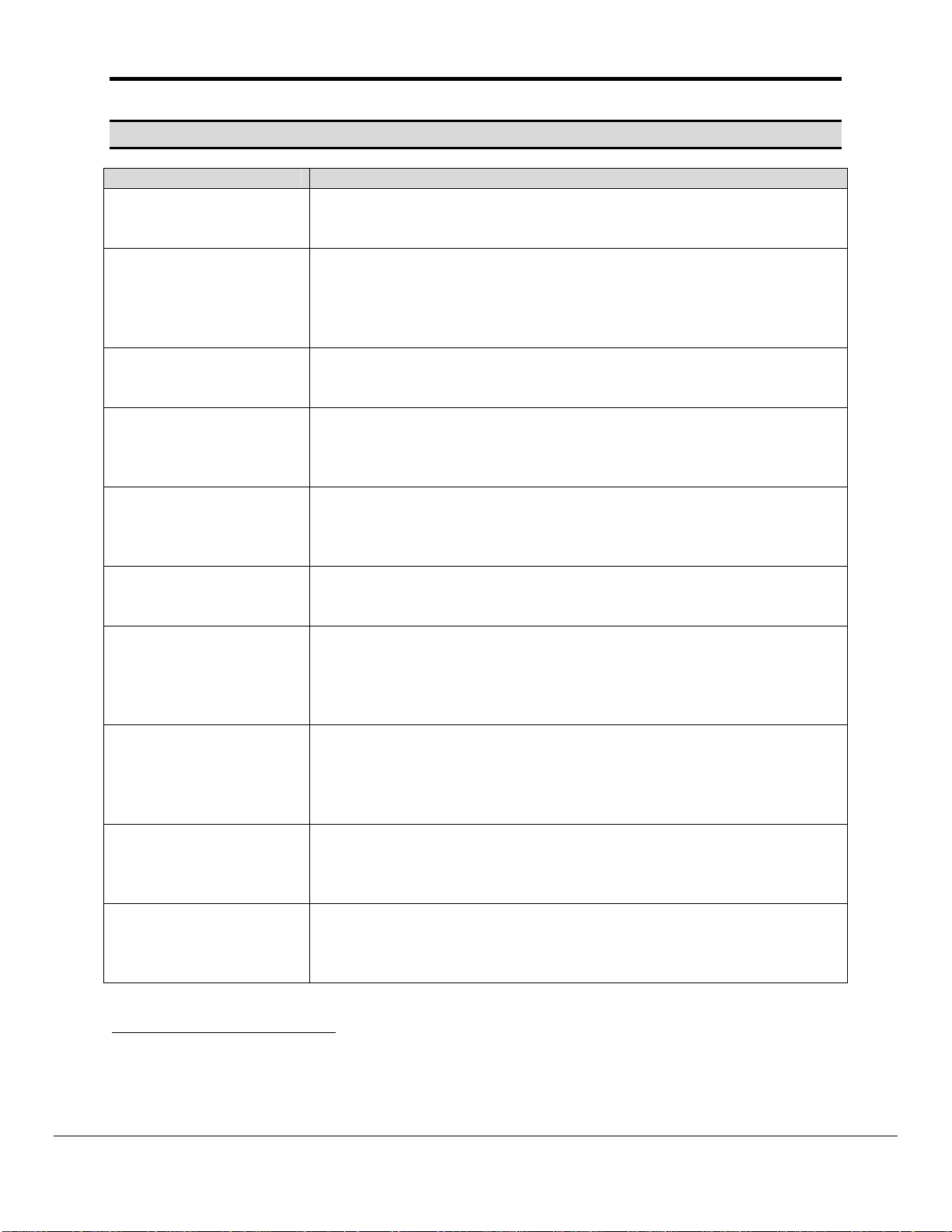
Appendix C. Driver Error Messages
Message Notes and Corrective Action
Set370:#1 FYI. Use an
Array called <%s> to
expose diagnostic info.
Set370:#2a. FYI. MD
Length=%d assigned by
driver.
Set370:#3 Err. No Write
MD's allowed.
Set370:#4 FYI. MD
param=Address has no
meaning. Ignoring.
Set370:#5 Err.
Diagnostic x
Set370:#6 Err. Array too
short. DA=%s MD=%s
Set370:#7 Err. Pressure
message can’t be
parsed. Abandoned!
Set370:#8* Err. Status
message can’t be
parsed. Abandoned!
Set370:#9 FYI. Default
to reading pressure.
Set370:#10 Err. DA=%s
too short. Act=%d
Rqd=%d MD=%s
This message is provided for information and may be ignored. Read
Appendix C.1 for more information.
This message is provided for information and may be ignored. The
message is printed when the Map Descriptor length in the
configuration file has not been specified. The driver makes the
correction by itself. To stop this message being printed, modify the
configuration file to match the length reported in the message.
This Driver cannot be used to write to the Setra device. Remove
any Map Descriptors whose function requires the FieldServer to
write to the Setra device.
3
This message is provided for information and may be ignored. The
address parameter is ignored by the driver. To stop this message
being printed, remove the address parameter from the configuration
file.
There are a few variations of this message. Note the variation and
report the error to FieldServer tech support. You cannot resolve this
error yourself. The error is printed when the driver executes a
diagnostic function used for QA testing.
The Data Array associated with the reported MD is too short to store
all the data returned by the Setra Gage. Increase the length of the
Data Array and of the Map Descriptor.
3
The response to a pressure reading request cannot be parsed by the
driver. Use the connection view to check the number of protocol
errors. If they keep rising, then take a log and report the error to
FieldServer Tech Support. If the protocol errors are occasional then
ignore them.
4
The response to a status reading request cannot be parsed by the
driver. Use the connection view to check the number of protocol
errors. If they keep rising, then take a log and report the error to
FieldServer Tech Support. If the protocol errors are occasional then
ignore them.
A Map Descriptor is found which does not have the ‘Gage_Function”
specified. The driver assumes your intention was to read the Gage’s
pressure. If you wish stop this message being printed then modify
the configuration file and specify the ‘Gage_Function’ = ‘Pressure’.
3
This message is printed when the driver is configured as a Server.
The Data Array associated with the reported MD is too short to store
the message. Modify the MD length and the DA length and try
again.
3
3
Modify the configuration CSV file. Download the modified file to the FieldServer and reset the
FieldServer for the changes to take effect
4
Message is printed once and then suppressed. This is to prevent the error log filling with redundant
repetition and thus obscuring other important information
FieldServer Technologies 1991 Tarob Court Milpitas, California 95035 USA Web:www.fieldServer.com
Tel: (408) 262-2299 Fax: (408) 262-9042 Toll_Free: 888-509-1970 email: support@fieldServer.com
.
.
Page 21
FS-8700-101_Setra Model 370 Digital Pressure Gage Manual Page 21 of 23
Appendix C.1. Exposing Driver Diagnostic Statistics
In addition to the standard FieldServer communication statistics described in Appendix C.2
and in the FieldServer Instruction Manual, this driver can also expose some driver statistics
by writing data to a data array. A special Data Array name is required. The driver
recognizes the Data Array by its name which must be "Setra370-Stats"
The following example shows how this Data Array can be configured. You can copy this
section of text directly into your CSV file.
Data_Arrays
Data_Array_Name, Data_Format, Data_Array_Length
setra370-stats, UINT32, 1000
The driver stores the following data. The location in the data array is obtained by
multiplying the port number by 100 and then using the location offset indicated in the table
below.
Offset + x
Where x = port_number*100
Physical Port 1 = Port Number 2
Physical Port 2 = Port number 1
Data Array Offset Contents
0 For FieldServer use only.
1 For FieldServer use only.
2 For FieldServer use only.
3 Increments by 1 each time a Client poll message is sent to a Gage.
4
5
6
7
8
9
10
Increments each time a Client poll message is sent to a Gage.
Increases by the number of bytes in the message.
Increments by 1 each time the Gage sends a response which is
completely unsuitable for data storage. Includes messages which
report the Gage is in a setup mode and is unable.
Increases each time the Gage receives a response which has some
hope of containing data. Increased by the number of bytes in that
message.
Increases each time the Gage receives a response which has some
hope of containing data. Increased by 1 each time.
Increments by one each time a status response contains a line
which appears not to be a heading but which does no appear to be
suitable for data extraction.
Increments by 1 each time a status response contains no data
which could be stored.
Increments by 1 each time a pressure reading response is not
suitable for data extraction and storage.
FieldServer Technologies 1991 Tarob Court Milpitas, California 95035 USA Web:www.fieldServer.com
Tel: (408) 262-2299 Fax: (408) 262-9042 Toll_Free: 888-509-1970 email: support@fieldServer.com
Page 22
FS-8700-101_Setra Model 370 Digital Pressure Gage Manual Page 22 of 23
Appendix C.2. Standard Driver Stats
Driver Statistics Recorded Explanation
PLC Read Messages sent Number of message sent to the Gage
PLC Write Messages sent Should be zero
PLC Bytes sent Total number of bytes sent by the Client side driver
Total number of messages of all types received (ACK,
PLC Message received
PLC Bytes received
Protocol
IC_Timeout
Timeout
Streaming
Exception
NAK, error response, normal response) on the Client side
driver.
Total number of bytes received by all message types on
the Client side driver.
Protocol errors are incremented when the Client side
cannot correctly parse a response message from the
Gage. This includes responses that are formatted
differently from what the driver expects, or messages that
report the Gage is ‘unable’ or in setup mode.
Incoming message buffer experiences an excessive
delay between incoming bytes
Client side messages that were not responded to by a
Server. Possibly a communications error or a command
was made to a unit that does not exist.
Message size was too large for the input buffer. This
should never occur.
Increments when a ‘status’ response contains a line with
insufficient information for storage but which may be a
heading.
FieldServer Technologies 1991 Tarob Court Milpitas, California 95035 USA Web:www.fieldServer.com
Tel: (408) 262-2299 Fax: (408) 262-9042 Toll_Free: 888-509-1970 email: support@fieldServer.com
Page 23

FS-8700-101_Setra Model 370 Digital Pressure Gage Manual Page 23 of 23
THIS PAGE INTENTIONALLY LEFT BLANK
FieldServer Technologies 1991 Tarob Court Milpitas, California 95035 USA Web:www.fieldServer.com
Tel: (408) 262-2299 Fax: (408) 262-9042 Toll_Free: 888-509-1970 email: support@fieldServer.com
 Loading...