

Page 1

APPLICABILITY & EFFECTIVITY
Effective for all systems manufactured after January 2013
Driver Manual
(Supplement to the FieldServer Instruction Manual)
FS-8700-01 Modbus RTU
&
FS-8700-08 Modbus ASCII
There are several similarities between these two drivers and we have
incorporated them into the same manual to ensure that our information
stays current. Although both drivers are referenced in this manual, they are
different drivers and need to be ordered separately."
Driver Version:
4.06
Document Revision:
3
A Sierra Monitor Company
Page 2

FS-8700-01 Modbus RTU/ASCIIFS-8700-01_Modbus_RTU.doc Driver Manual Table of Contents
TABLE OF CONTENTS
1 Modbus RTU/ Modbus ASCII Description ....................................................................................................... 3
2 Driver Scope of Supply ................................................................................................................................... 3
2.1 Supplied by FieldServer Technologies for this driver ................................................................................... 3
2.2 Provided by Supplier of 3rd Party Equipment ............................................................................................... 3
3 Hardware Connections ................................................................................................................................... 4
4 Data Array Parameters ................................................................................................................................... 5
5 Configuring the FieldServer as a Modbus RTU or Modbus ASCII Client. .......................................................... 6
5.1 Client Side Connection Parameters .............................................................................................................. 6
5.2 Client Side Node Parameters ....................................................................................................................... 7
5.3 Client Side Map Descriptor Parameters ....................................................................................................... 8
5.3.1 FieldServer Related Map Descriptor Parameters ..................................................................................... 8
5.3.2 Driver Related Map Descriptor Parameters ............................................................................................. 8
5.3.3 Timing Parameters ................................................................................................................................... 9
5.3.4 Map Descriptor Examples. ..................................................................................................................... 10
6 Configuring the FieldServer as a Modbus RTU or Modbus ASCII Server ........................................................ 11
6.1 Server Side Connection Parameters ........................................................................................................... 11
6.2 Server Side Node Parameters .................................................................................................................... 12
6.3 Server Side Map Descriptor Parameters .................................................................................................... 13
6.3.1 FieldServer Specific Map Descriptor Parameters ................................................................................... 13
6.3.2 Driver Specific Map Descriptor Parameters ........................................................................................... 13
6.3.3 Map Descriptor Examples ...................................................................................................................... 14
6.3.4 Slave_Id .................................................................................................................................................. 14
Appendix A. Useful Features – Modbus RTU ........................................................................................................ 15
Appendix A.1. Managing Floating points with Modbus ........................................................................................... 15
Appendix A.1.1. Transferring non-integer values with one register ................................................................. 15
Appendix A.1.2. Transferring 32 bit values with two registers ......................................................................... 16
Appendix A.2. Node_Offline_Response................................................................................................................... 16
Appendix B. Troubleshooting ............................................................................................................................... 18
Appendix B.1. Server Configuration of System Station Address.............................................................................. 18
Appendix C. Vendor Information ......................................................................................................................... 19
Appendix C.1. Connection to York Modbus Microgateway ..................................................................................... 19
Appendix C.2. Modbus ASCII - Examples of FieldServer setup for typical clients .................................................... 19
Appendix C.2.1. FieldServer with GE Cimplicity as client .................................................................................. 19
Appendix C.2.2. FieldServer with Intellution FIX as a client .............................................................................. 19
Appendix D. Reference ........................................................................................................................................ 21
Appendix D.1. Data Types ........................................................................................................................................ 21
Appendix D.2. Single Writes .................................................................................................................................... 21
FieldServer Technologies 1991 Tarob Court Milpitas, California 95035 USA Web: www.fieldserver.com
Tel: (408) 262 2299 Fax: (408) 262 2269 Toll Free: (888) 509 1970 email: support@fieldserver.com
Page 3

FS-8700-01 Modbus RTU/ASCIIFS-8700-01_Modbus_RTU.doc Driver Manual Page 3 of 21
FieldServer Technologies PART #
Description
FS-8915-10
UTP cable (7 foot) for RS-232 use 1
PART #
Description
Modbus RTU or Modbus ASCII device
1
1 MODBUS RTU/ M O D B US ASCII DE SC R I P TION
The Modbus RTU and Modbus ASCII drivers allow the FieldServer to transfer data to and from devices using
Modbus RTU or Modbus ASCII protocol respectively. Data can be transferred over either RS-232 or RS-485. The
driver was developed for Modbus Application Protocol Specification V1.1a" from Modbus-IDA. The specification
can be found at www.modbus.org. The FieldServer can emulate either a Server or Client.
The information that follows describes how to expand upon the factory defaults provided in the configuration files
included with the FieldServer.
There are various register mapping models being followed by various vendors
To cover all these models FieldServer uses the following three Models
Modicon_5digit – Use this format where addresses are defined in 0xxxx, 1xxxx, 3xxxx or 4xxxx format. A
maximum of 9999 registers can be mapped of each type. This is FieldServer driver’s default format.
ADU –Application Data Unit address. Use this format where addresses of each type are defined in the
range 1-65536
PDU –Protocol Data unit address. Use this format where addresses of each type are defined in the range
0-65535.
The key difference between ADU and PDU is for example if Address_Type is ADU and address is 1, the driver will
poll for register 0. If Address_Type is PDU, the driver will poll for address 1.
Note 1: If vendor document shows addresses in extended Modicon (i.e. 6 digit) format like 4xxxxx then consider
these addresses as xxxxx (omit the first digit) and use either ADU or PDU
Note 2: The purpose of providing 3 different ways of addressing the Modbus registers is to allow the user to
choose the addressing system most compatible with the address list being used. At the protocol level, the same
protocol specification is used for all three with the exception of the limited address range for Modicon_5digit.
2 DRIVER SCOPE OF SU P PLY
2.1 Sup plied by FieldSe r v e r Technologies fo r t h i s driver
2.2 Provided by Supplier of 3
rd
Party Equipment
This cable is necessary for connection to the driver. It is shipped with the FieldServer and not separately with the driver.
FieldServer Technologies 1991 Tarob Court Milpitas, California 95035 USA Web: www.fieldserver.com
Tel: (408) 262 2299 Fax: (408) 262 2269 Toll Free: (888) 509 1970 email: support@fieldserver.com
Page 4
FS-8700-01 Modbus RTU/ASCIIFS-8700-01_Modbus_RTU.doc Driver Manual Page 4 of 21
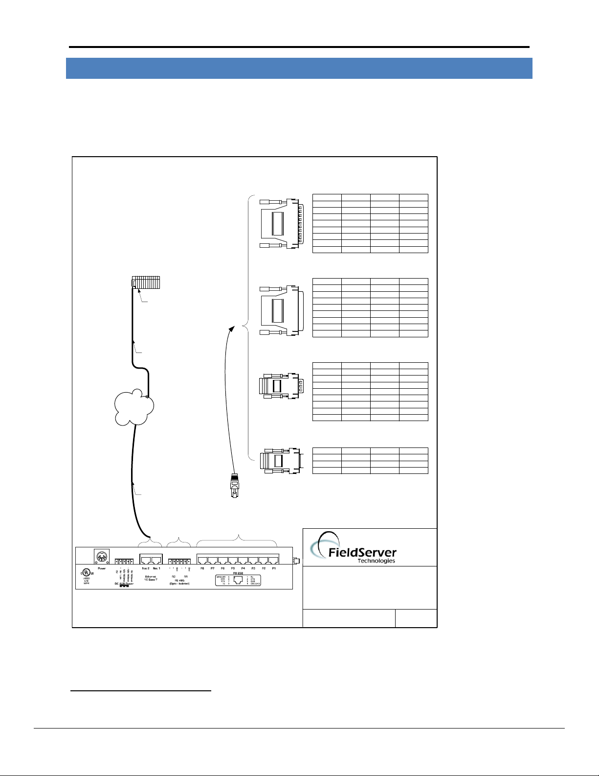
RJ45 to
RS-232
Connector
Connect
to 2-wire
RS-485
network
OR
RJ45 Connector
Typical DB9/DB25
kit assemblies are
shown here. Refer
to the third party
device literature
for exact
configuration
required.
DB25M
FUNCTION FROM TO COLOUR
Rx RJ45-01 DB9F-03 WHITE
GND RJ45-04 DB9F-05 GREEN
Tx RJ45-08 DB9F-02 BLUE
FUNCTION FROM TO COLOUR
RX RJ45-01 DB25M-03 WHITE
CTS RJ45-02 DB25M-05 BROWN
DSR RJ45-03 YELLOW
GND RJ45-04 DB25M-07 GREEN
GND RJ45-05 RED
TX RJ45-08 DB25M-02 BLUE
RTS RJ45-07 DB25M-04 ORANGE
DTR RJ45-06 BLACK
8917-01 WIRE LIST
FUNCTION FROM TO COLOUR
RX RJ45-01 DB25F-02 WHITE
CTS RJ45-02 DB25F-04 BROWN
DSR RJ45-03 YELLOW
GND RJ45-04 DB25F-07 GREEN
GND RJ45-05 RED
TX RJ45-08 DB25F-03 BLUE
RTS RJ45-07 DB25F-05 ORANGE
DTR RJ45-06 BLACK
8917-04 WIRE LIST
DB25F
DB9M
FUNCTION FROM TO COLOUR
RX RJ45-01 DB9M-02 GREY
CTS RJ45-02 DB9M08 BROWN
DSR RJ45-03 DB9M-06 YELLOW
GND RJ45-04 DB9M-05 GREEN
GND RJ45-05 RED
TX RJ45-08 DB9M-03 BLUE
RTS RJ45-07 DB9M-07 ORANGE
DTR RJ45-06 DB9M-04 BLACK
8917-03 WIRE LIST
BASE NAME:
FILE NAME:
FIELDSERVER
GENERIC
CONNECTION DIAGRAM
DATE: 8/16/05
BY: MC
(408)-262-2299
DB9F
8917-02 WIRE LIST
PLC
Ethernet Interface
FS-8915-10
FS-8915-10
Site Ethernet
2
3 HARDWARE C O N N E CT ION S
It is possible to connect a Modbus RTU or Modbus ASCII device to any of the existing serial ports on the
FieldServer2. These ports simply need to be configured for the appropriate driver in the configuration file.
Configure the Modbus RTU or Modbus ASCII device according to manufacturer’s instructions.
Not all ports shown are necessarily supported by the hardware. Consult the appropriate Instruction manual for details of the ports available
on specific hardware.
FieldServer Technologies 1991 Tarob Court Milpitas, California 95035 USA Web: www.fieldserver.com
Tel: (408) 262 2299 Fax: (408) 262 2269 Toll Free: (888) 509 1970 email: support@fieldserver.com
Page 5

FS-8700-01 Modbus RTU/ASCIIFS-8700-01_Modbus_RTU.doc Driver Manual Page 5 of 21
Section Title
Data_Arrays
Column Title
Function
Legal Values
Data_Array_Name
Provide name for Data Array
Up to 15 alphanumeric characters
Data_Array_Format
Provide data format. Each Data Array can only take
on one format.
FLOAT, BIT, UInt16, SInt16,
Packed_Bit, Byte, Packed_Byte,
Swapped_Byte
Data_Array_Length
Number of Data Objects. Must be larger than the
data storage area required by the Map Descriptors
for the data being placed in this array.
1-10, 000
// Data Arrays
Data_Arrays
Data_Array_Name
, Data_Array_Format
, Data_Array_Length
DA_AI_01
, UInt16
, 200
DA_AO_01
, UInt16
, 200
DA_DI_01
, Bit
, 200
DA_DO_01
, Bit
, 200
4 DATA A R R AY PARAMETERS
Data Arrays are “protocol neutral” data buffers for storage of data to be passed between protocols. It is necessary
to declare the data format of each of the Data Arrays to facilitate correct storage of the relevant data.
Example
FieldServer Technologies 1991 Tarob Court Milpitas, California 95035 USA Web: www.fieldserver.com
Tel: (408) 262 2299 Fax: (408) 262 2269 Toll Free: (888) 509 1970 email: support@fieldserver.com
Page 6

FS-8700-01 Modbus RTU/ASCIIFS-8700-01_Modbus_RTU.doc Driver Manual Page 6 of 21
Section Title
Connections
Column Title
Function
Legal Values
Port
Specify which port the device is connected to the FieldServer
P1-P8, R1-R23
Baud*
Specify baud rate
110 – 115200, standard baud
rates only. 9600
Parity*
Specify parity
Even, Odd, None
Data_Bits*
Specify data bits
7, 8
Stop_Bits*
Specify stop bits
1,2
Protocol
Specify protocol used
Modbus RTU
Modbus _RTU
Modbus ASCII
MB_ASCII
Poll_Delay*
Time between internal polls
0-32000s, 0.05s
// Client Side Connections
Connections
Port
, Baud
, Parity
, Data_Bits
, Stop_Bits
, Protocol
, Handshaking
, Poll_Delay
P1
, 9600
, None
, 8
, 1
, Modbus _RTU4
, None
, 0.100s
3
4
5 CONFIGUR I N G T HE FIELDSERVER A S A M O DBUS RTU OR MODB U S A SCII CLIENT.
For a detailed discussion on FieldServer configuration, please refer to the FieldServer Configuration Manual. The
information that follows describes how to expand upon the factory defaults provided in the configuration files
included with the FieldServer (See “.csv” sample files provided with the FieldServer).
This section documents and describes the parameters necessary for configuring the FieldServer to communicate
with a Modbus RTU or Modbus ASCII Server.
5.1 Client Side Connect ion Parameters
Example
Not all ports shown are necessarily supported by the hardware. Consult the appropriate Instruction manual for details of the ports available
on specific hardware.
Change protocol to MB_ASCII to use Modbus ASCII protocol
FieldServer Technologies 1991 Tarob Court Milpitas, California 95035 USA Web: www.fieldserver.com
Tel: (408) 262 2299 Fax: (408) 262 2269 Toll Free: (888) 509 1970 email: support@fieldserver.com
Page 7

FS-8700-01 Modbus RTU/ASCIIFS-8700-01_Modbus_RTU.doc Driver Manual Page 7 of 21
Section Title
Nodes
Column Title
Function
Legal Values
Node_Name
Provide name for Node
Up to 32 alphanumeric
characters
Node_ID
Modbus station address of physical Server Node
1-255
Protocol
Specify protocol used
Modbus RTU
Modbus_RTU
Modbus ASCII
MB_ASCII
Port
Specify which port the device is connected to the FieldServer
P1-P8, R1-R2
3
Address_Type5
Specify Register Mapping Model
ADU,PDU, -,
Modicon_5digit
Write_Fnc*
Set to Multiple if Remote Server Node only supports Write Multiple
function code 15 & 16
Multiple, -,
Write_Length*
Set to Map Descriptor Length if write-thru operation should write
all registers as specified by Map Descriptor length.
By default write-thru writes a single register.
If Write_Length also specified on Map Descriptor, Map Descriptor’s
parameter will be used.
Map Descriptor Length, -,
1,
// Client Side Nodes
// For devices where 65536 addresses are available in each memory area.
Nodes
Node_Name
, Node_ID
, Protocol
, Port
,Address_Type
Modbus device 1
, 1
, Modbus _RTU6
, P1
,ADU
Modbus device 2
, 2
, Modbus_RTU
, P1
,PDU
// For devices where only 9999 registers are available in each memory area.
Nodes
Node_Name
, Node_ID
, Protocol
, Port
Modbus device 3
, 3
, Modbus_RTU
, P1
5
6
5.2 Client Side Node P a r a m eters
Example:
Optional for Modicon 5 digit devices
Change protocol to MB_ASCII to use Modbus ASCII protocol
FieldServer Technologies 1991 Tarob Court Milpitas, California 95035 USA Web: www.fieldserver.com
Tel: (408) 262 2299 Fax: (408) 262 2269 Toll Free: (888) 509 1970 email: support@fieldserver.com
Page 8

FS-8700-01 Modbus RTU/ASCIIFS-8700-01_Modbus_RTU.doc Driver Manual Page 8 of 21
Column Title
Function
Legal Values
Map_Descriptor_Name
Name of this Map Descriptor
Up to 32 alphanumeric characters
Data_Array_Name
Name of Data Array where data is
to be stored in the FieldServer
One of the Data Array names from Section 4
Data_Array_Offset
Starting location in Data Array
0 to (Data_Array_Length -1) as specified in Section
4
Function
Function of Client Map
Descriptor.
Wrbc, Wrbx, Rdbc, Arcs. Refer to Error! Reference
source not found. for more information.
Column Title
Function
Legal Values
Node_Name
Name of Node to fetch data from
One of the Node names specified in
“Client Node Descriptor” above
Data_Type7
Specify memory area. Refer to Appendix
A.1.2 on how to transfer 32 Bit values
using Modbus registers.
Address_Type = ADU
Coil, Discrete_Input, Input_Register,
Holding_Register, Single_Coil,
Single_Register, Slave_Id
Address_Type = PDU
FC01, FC02, FC03, FC04,
FC05, FC06, FC15, FC16
Address_Type = Modicon_5digit
- (Dash), Single_Register, Single_Coil
All Address_Type
Float_Reg, 32-Bit_Reg, Input_Float,
Input_Reg_32Bit
Address
Starting address of read block
Address_Type = ADU
1-65536
Address_Type = PDU
0-65535
Address_Type = Modicon_5digit
40001, 30001, etc
Length
Length of Map Descriptor.
1-125 (For Analog polls),
1-800 (For Binary polls).
Write_Length*
Set to Map Descriptor Length if write-thru
operation should write all registers as
specified by length parameter.
By default write-thru writes a single
register.
Map Descriptor Length, 1,
Data_Array_Low_Scale*
Scaling zero in Data Array
Any signed 32 bit integer in the range:
7
5.3 Client Side Map Desc r i p t o r Parameters
5.3.1 FieldServer Relat e d M a p Descriptor Paramete r s
5.3.2 Driver Related Map De s c r i p t o r Parameters
Optional only for Modicon_5digit addressing, and only if Single writes do not need to be forced
FieldServer Technologies 1991 Tarob Court Milpitas, California 95035 USA Web: www.fieldserver.com
Tel: (408) 262 2299 Fax: (408) 262 2269 Toll Free: (888) 509 1970 email: support@fieldserver.com
Page 9

FS-8700-01 Modbus RTU/ASCIIFS-8700-01_Modbus_RTU.doc Driver Manual Page 9 of 21
-2,147,483,648 to 2,147,483,647. 0
Data_Array_High_Scale*
Scaling max in Data Array
Any signed 32 bit integer in the range:
-2,147,483,648 to 2,147,483,647. 100
Node_Low_Scale*
Scaling zero in Connected Node
Any signed 32 bit integer in the range:
-2,147,483,648 to 2,147,483,647. 0
Node_High_Scale*
Scaling max in Connected Node
Any signed 32 bit integer in the range:
-2,147,483,648 to 2,147,483,647. 100
Column Title
Function
Legal Values
Scan_Interval*
Rate at which data is polled
0-32000, 1
5.3.3 Timing Parameters
FieldServer Technologies 1991 Tarob Court Milpitas, California 95035 USA Web: www.fieldserver.com
Tel: (408) 262 2299 Fax: (408) 262 2269 Toll Free: (888) 509 1970 email: support@fieldserver.com
Page 10

FS-8700-01 Modbus RTU/ASCIIFS-8700-01_Modbus_RTU.doc Driver Manual Page 10 of 21
// Client Side Map Descriptors
// Note: All three examples below are addressing the same Modbus registers.
// For Nodes where Address_Type is ADU
Map_Descriptors
Map_Descriptor_Name
, Data_Array_Name
, Data_Array_Offset
, Function
, Node_Name
, Data_Type
, Address
, Length
,Scan_Interval
CMD_AI_01
, DA_AI_01
, 0
, Rdbc
, MODBUS DEVICE1
, Input_Register
, 1
, 20
,1.000s
CMD_AO_01
, DA_AO_01
, 0
, Rdbc
, MODBUS DEVICE1
, Holding_Register
, 1
, 20
,1.000s
CMD_DI_01
, DA_DI_01
, 0
, Rdbc
, MODBUS DEVICE1
, Discrete_Input
, 1
, 20
,1.000s
CMD_DO_01
, DA_DO_01
, 0
, Rdbc
, MODBUS DEVICE1
, Coil
, 1
, 20
,1.000s
// For Nodes where Address_Type is PDU
Map_Descriptors
Map_Descriptor_Name
, Data_Array_Name
, Data_Array_Offset
, Function
, Node_Name,
, Data_Type
, Address
, Length
,Scan_Interval
CMD_AI_02
, DA_AI_02
, 0
, Rdbc
, MODBUS DEVICE2
, FC04
, 0
, 20
,1.000s
CMD_AO_02
, DA_AO_02
, 0
, Rdbc
, MODBUS DEVICE2
, FC03
, 0
, 20
,1.000s
CMD_DI_02
, DA_DI_02
, 0
, Rdbc
, MODBUS DEVICE2
, FC02
, 0
, 20
,1.000s
CMD_DO_02
, DA_DO_02
, 0
, Rdbc
, MODBUS DEVICE2
, FC01
, 0
, 20
,1.000s
// For Nodes where Address_Type is Modicon_5digit.
Map_Descriptors
Map_Descriptor_Name
, Data_Array_Name
, Data_Array_Offset
, Function
, Node_Name,
, Address
, Length
, Scan_Interval
CMD_AI_03
, DA_AI_03
, 0
, Rdbc
, MODBUS DEVICE3
, 30001
, 20
, 1.000s
CMD_AO_03
, DA_AO_03
, 0
, Rdbc
, MODBUS DEVICE3
, 40001
, 20
, 1.000s
CMD_DI_03
, DA_DI_03
, 0
, Rdbc
, MODBUS DEVICE3
, 10001
, 20
, 1.000s
CMD_DO_03
, DA_DO_03
, 0
, Rdbc
, MODBUS DEVICE3
, 00001
, 20
, 1.000s
5.3.4 Map Descriptor Exam pl e s.
FieldServer Technologies 1991 Tarob Court Milpitas, California 95035 USA Web: www.fieldserver.com
Tel: (408) 262 2299 Fax: (408) 262 2269 Toll Free: (888) 509 1970 email: support@fieldserver.com
Page 11

FS-8700-01 Modbus RTU/ASCIIFS-8700-01_Modbus_RTU.doc Driver Manual Page 11 of 21
Section Title
Connections
Column Title
Function
Legal Values
Port
Specify which port the device is connected
to the FieldServer
P1-P8, R1-R28
Baud*
Specify baud rate
110 – 115200, standard baud rates only, 9600
Parity*
Specify parity
Even, Odd, None
Data_Bits*
Specify data bits
7, 8
Stop_Bits*
Specify stop bits
1, 2
Protocol
Specify protocol used
Modbus RTU
Modbus_RTU
Modbus ASCII
MB_ASCII
// Server Side Connections
Connections
Port
, Baud
, Parity
, Data_Bits
, Stop_Bits
, Protocol
P1
, 9600
, None
, 8
, 1
, Modbus_RTU
8
6 CONFIGUR I N G T HE FIELDSERVER A S A M O DBUS RTU OR MODBUS A SCII SERVER
For a detailed discussion on FieldServer configuration, please refer to the FieldServer Configuration Manual. The
information that follows describes how to expand upon the factory defaults provided in the configuration files
included with the FieldServer (See “.csv” sample files provided with the FieldServer).
This section documents and describes the parameters necessary for configuring the FieldServer to communicate
with a Modbus RTU or Modbus ASCII Client.
The configuration file tells the FieldServer about its interfaces, and the routing of data required. In order to enable
the FieldServer for Modbus RTU or Modbus ASCII communications, the driver independent FieldServer buffers
need to be declared in the “Data Arrays” section, the FieldServer virtual Node(s) needs to be declared in the
“Server Side Nodes” section, and the data to be provided to the clients needs to be mapped in the “ Server Side
Map Descriptors” section. Details on how to do this can be found below.
Note that in the tables, * indicates an optional parameter, with the bold legal value being the default.
6.1 Server Side Connectio n Parameters
Example
Change protocol to MB_ASCII to use Modbus ASCII protocol
Not all ports shown are necessarily supported by the hardware. Consult the appropriate Instruction manual for details of the ports available
on specific hardware.
FieldServer Technologies 1991 Tarob Court Milpitas, California 95035 USA Web: www.fieldserver.com
Tel: (408) 262 2299 Fax: (408) 262 2269 Toll Free: (888) 509 1970 email: support@fieldserver.com
Page 12

FS-8700-01 Modbus RTU/ASCIIFS-8700-01_Modbus_RTU.doc Driver Manual Page 12 of 21
Section Title
Nodes
Column Title
Function
Legal Values
Node_Name
Provide name for Node
Up to 32 alphanumeric
characters
Node_ID
Node ID of physical Server Node
1 – 255
Protocol
Specify protocol used
Modbus RTU
Address_Type9
Specify Register Mapping Model
ADU,PDU, -,
Modicon_5digit
Node_Offline_Response*
Set the FieldServer response to the Modbus RTU
Client when the Server Node supplying the data has
gone offline
No_Response,
Old_Data,
Zero_Data,
FFFF_Data,
Refer to Appendix A.2 for
further information.
Node_Description*
Specify Node description text
Any string up to 99
characters long, -
// Server Side Nodes
// For devices where 65536 addresses are available in each memory area.
Nodes
Node_Name
, Node_ID
, Protocol
, Address_Type
MB_Srv_11
, 11
, Modbus_RTU
, ADU
MB_Srv_12
, 12
, Modbus_RTU
, PDU
// For devices where only 9999 registers are available in each memory area.
Nodes
MB_Srv_13
, 13
, Modbus_RTU
, Modicon_5digit
MB_Srv_14
, 14
, Modbus_RTU
, -
9
6.2 Server Side Node P a r a m eters
Example
Change protocol to MB_ASCII to use Modbus ASCII protocol
Optional for Modicon 5 digit devices
FieldServer Technologies 1991 Tarob Court Milpitas, California 95035 USA Web: www.fieldserver.com
Tel: (408) 262 2299 Fax: (408) 262 2269 Toll Free: (888) 509 1970 email: support@fieldserver.com
Page 13

FS-8700-01 Modbus RTU/ASCIIFS-8700-01_Modbus_RTU.doc Driver Manual Page 13 of 21
Column Title
Function
Legal Values
Map_Descriptor_Name
Name of this Map Descriptor
Up to 32 alphanumeric characters
Data_Array_Name
Name of Data Array where data is to be
stored in the FieldServer
One of the Data Array names from
Section 4
Data_Array_Offset
Starting location in Data Array
0 to (Data_Array_Length -1) as specified
in Section 4
Function
Function of Server Map Descriptor
Passive
Column Title
Function
Legal Values
Node_Name
The name of the Node
being represented.
One of the Node names specified in Section 6.2
Data_Type10
Specify memory area
Address_Type = ADU
Coil, Discrete_Input, Input_Register, Holding_Register,
Single_Coil, Single_Register, Slave_ID
Address_Type = PDU
FC01, FC02, FC03, FC04,
FC05, FC06, FC15, FC16
Address_Type = Modicon_5digit
- (Dash), Single_Register, Single_Coil
Length*
Length of Map Descriptor
1-10000, 1
Address
Starting address of read
block
Address_Type = ADU
1-65536
Address_Type = PDU
0-65535
Address_Type = Modicon_5digit
40001, 30001, etc
Data_Array_Low_Scale*
Scaling zero in Data Array
Any signed 32 bit integer in the range:
-2,147,483,648 to 2,147,483,647. 0
Data_Array_High_Scale*
Scaling max in Data Array
Any signed 32 bit integer in the range:
-2,147,483,648 to 2,147,483,647. 100
Node_Low_Scale*
Scaling zero in Connected
Node
Any signed 32 bit integer in the range:
-2,147,483,648 to 2,147,483,647. 0
Node_High_Scale*
Scaling max in Connected
Node
Any signed 32 bit integer in the range:
-2,147,483,648 to 2,147,483,647. 100
10
6.3 Server Side Map Descri pt o r Parameters
6.3.1 FieldServer Speci f i c M ap Descriptor Param e t e r s
6.3.2 Driver Specific Map D e s c r i p t o r Parameters
Optional only for Modicon_5digit addressing, and only if Single writes do not need to be forced
FieldServer Technologies 1991 Tarob Court Milpitas, California 95035 USA Web: www.fieldserver.com
Tel: (408) 262 2299 Fax: (408) 262 2269 Toll Free: (888) 509 1970 email: support@fieldserver.com
Page 14

FS-8700-01 Modbus RTU/ASCIIFS-8700-01_Modbus_RTU.doc Driver Manual Page 14 of 21
// Server Side Map Descriptors where Node Address_Type is ADU
// Note: All three examples below are addressing the same Modbus registers.
// For Nodes where Address_Type is ADU
Map_Descriptors
Map_Descriptor_Name
, Data_Array_Name
, Data_Array_Offset
, Function
, Node_Name
, Data_Type
, Address
, Length
, Data_Array_Low_Scale
, Data_Array_High_Scale
, Node_Low_Scale
, Node_High_Scale
SMD_AI_01
, DA_AI_01
, 0
, Passive
, MB_Srv_11
, Input_Register
, 1
, 200
, 0
, 100
, 0
, 10000
SMD_AO_01
, DA_AO_01
, 0
, Passive
, MB_srv_11
, Holding_Register
, 1
, 200
, 0
, 100
, 0
, 10000
// Server Side Map Descriptors where Node Address_Type is PDU
Map_Descriptors
Map_Descriptor_Name
, Data_Array_Name
, Data_Array_Offset
, Function
, Node_Name
, Data_Type
, Address
, Length
, Data_Array_Low_Scale
, Data_Array_High_Scale
, Node_Low_Scale
, Node_High_Scale
SMD_AI_02
, DA_AI_02
, 0
, Passive
, MB_Srv_12
, FC04
, 0
, 200
, 0
, 100
, 0
, 10000
SMD_AO_02
, DA_AO_02
, 0
, Passive
, MB_srv_12
, FC03
, 0
, 200
, 0
, 100
, 0
, 10000
// For Nodes where Address_Type is Modicon_5digit.
Map_Descriptors
Map_Descriptor_Name
, Data_Array_Name
, Data_Array_Offset
, Function
, Node_Name
, Address
, Length
, Data_Array_Low_Scale
, Data_Array_High_Scale
, Node_Low_Scale
, Node_High_Scale
SMD_AI_01
, DA_AI_01
, 0
, Passive
, MBP_Srv_13
, 30001
, 200
, 0
, 100
, 0
, 10000
SMD_AO_01
, DA_AO_01
, 0
, Passive
, MBP_Srv_13
, 40001
, 200
, 0
, 100
, 0
, 10000
Map_Descriptors
Map_Descriptor_Name
, Data_Array_Name
, Data_Array_Offset
, Function
, Node_Name
, Address
, Length
, Data_Type
SMD_DO1
, DA_DO_01
, 0
, Passive
, RTU_Srv_21
, 00001
, 1
, Slave_ID
Length is not
used, revert to
default of 1
6.3.3 Map Descriptor Exam pl e s
6.3.4 Slave_Id
The following Map Descriptor is used to respond to the Report Slave_Id request. The FieldServer's Slave_Id is 11 and the run status depends upon the data
validity at the specified offset in the specified Data Array - if the data is valid, the status will be 255 (running) otherwise the status will be 0 (off).
FieldServer Technologies 1991 Tarob Court Milpitas, California 95035 USA Web: www.fieldserver.com
Tel: (408) 262 2299 Fax: (408) 262 2269 Toll Free: (888) 509 1970 email: support@fieldserver.com
Page 15

FS-8700-01 Modbus RTU/ASCIIFS-8700-01_Modbus_RTU.doc Driver Manual Page 15 of 21
Map_Descriptors
Map_Descriptor_Name
, Data_Array_Name
, Data_Array_Offset
, Function
, Node_Name
, Address
, Length
, Data_Array_Low_Scale
, Data_Array_High_Scale
, Node_Low_Scale
, Node_High_Scale
SMD_AI1
, DA_AI_01
, 0
, Passive
, MBP_Srv_11
, 30001
, 200
, 0
, 100
, 0
, 10000
SMD_AO1
, DA_AO_01
, 0
, Passive
, MBP_Srv_11
, 40001
, 200
, 0
, 100
, 0
, 10000
Appendix A. Useful Features – Modbus RTU
Appendix A.1. Managing Floating points with Modbus
Modbus as a standard does not support floating point formats. Many vendors have written higher level communications software to use two 16 bit registers
to represent floating point or 32 bit integers. This requires conversion software on both ends of the communication channel. The FieldServer supports this
function and also provides other options to resolve this issue.
Appendix A.1.1. Transferr i ng n o n-integer v a l u e s w ith one register
It is possible to represent values higher than 32767 using one register in one of two ways:
Declare data arrays as type Uint16 (Unsigned integer). This will give you a range from 0 to 65535.
Use the scaling function on the FieldServer, which will allow you to set up any range, with 16 bit resolution.
The following example shows how scaling can be achieved on the Server side of the configuration. Note that scaling can also be done on the Client side to
scale down a value that was scaled up by a Modbus vendor. Further information regarding scaling can be found in the FieldServer Configuration manual.
Example :
This example multiplies the values in the data array by 100 (10000 on Node_High_Scale is 100X larger than 100 on Data_Array_High_Scale). This is most
commonly used when the user wants to introduce values after the decimal point. For example, a value of 75.6 will be sent as 7560, which can then be rescaled
by the Modbus master.
FieldServer Technologies 1991 Tarob Court Milpitas, California 95035 USA Web: www.fieldserver.com
Tel: (408) 262 2299 Fax: (408) 262 2269 Toll Free: (888) 509 1970 email: support@fieldserver.com
Page 16

FS-8700-01 Modbus RTU/ASCIIFS-8700-01_Modbus_RTU.doc Driver Manual Page 16 of 21
Data_Arrays
Data_Array_Name
, Data_Format
, Data_Array_Length
DA1
, Float
, 20
DA2
, UInt32
, 20
DA3
, Float
, 20
DA4
,UInt32
, 20
// Client Side Map Descriptors
// For Nodes where Address_Type is PDU
Map_Descriptors
Map_Descriptor_Name
, Data_Array_Name
, Data_Array_Offset
, Function
, Node_Name,
, Data_Type
, Address
, Length
,Scan_Interval
CMD_AO_01
, DA1
, 0
, Rdbc
, MODBUS DEVICE2
, Float_Reg
, 0
, 20
,1.000s
CMD_AO_02
, DA2
, 0
, Rdbc
, MODBUS DEVICE2
, 32-Bit_Reg
, 0
, 20
,1.000s
CMD_AI_01
, DA3
, 0
, Rdbc
, MODBUS DEVICE2
, Input_Float
, 0
, 20
,1.000s
CMD_AI_02
, DA4
, 0
, Rdbc
, MODBUS DEVICE2
, Input_Reg_32Bit
, 0
, 20
,1.000s
Appendix A.1.2. Transferr ing 3 2 b it values with two r e g i s t e rs
If a Modbus Server sends two consecutive registers to the FieldServer representing either a floating point value or
a 32 bit integer value, the FieldServer can combine and decode these registers back into their original format. To
do this declare Data Array of type Float or UINT32 and set the Map Descriptor Data_Type as ‘Float_Reg’ or ‘32Bit_Reg’ etc
Example:
Each Map Descriptor will read 20 pairs of registers and store them as 32-bit floating number or 32-bit Integer.
If somehow server device send swapped registers (low value register first) then use corresponding _swap
data_types.
Note: Please note starting addresses per address_type, see section 5.3.2
Appendix A.2. Node_Offline_Response
This function is specific to the Modbus RTU driver.
In systems where data is being collected from multiple Server Nodes and made available on a FieldServer
configured as a Modbus RTU Server, when a Server Node goes offline the default behavior of the FieldServer
would be to stop responding to polls for this data. This might not be what the user wants. Various options exist
making it possible to signal that the data quality has gone bad without creating error conditions in systems
sensitive to the default option.
The following options can be configured under the Node parameter, Node_Offline_Response, to set the response
of the FieldServer to the Modbus RTU Client when the Server Node supplying the data is offline:
No_Response - this is the default option. The FieldServer simply does not respond when the
corresponding Server Node is offline.
Old_Data - The FieldServer will respond, but with the last known value of the data. This maintains the
communication link in an active state, but may hide the fact that the Server Node is offline.
FieldServer Technologies 1991 Tarob Court Milpitas, California 95035 USA Web: www.fieldserver.com
Tel: (408) 262 2299 Fax: (408) 262 2269 Toll Free: (888) 509 1970 email: support@fieldserver.com
Page 17

FS-8700-01 Modbus RTU/ASCIIFS-8700-01_Modbus_RTU.doc Driver Manual Page 17 of 21
Nodes
Node_Name
, Node_ID
, Protocol
, Node_Offline_Response
, Port
DEV11
, 11
, Modbus_RTU
, No_Response
, -
DEV12
, 12
, Modbus_RTU
, Old_Data
, -
DEV15
, 15
, Modbus_RTU
, Zero_Data
, -
DEV16
, 16
, Modbus_RTU
, FFFF_Data
, -
DEV17
, 17
, Modbus_RTU
, Exception_4.
, -
DEV18
, 18
, Modbus_RTU
, Gateway_Path_Unavailable
, -
Zero_Data - The FieldServer will respond, but with the data values set to zero. If the user normally expects
non-zero values, this option will signal the offline condition without disrupting communications.
FFFF_Data - The FieldServer will respond, but with the data values set to FFFF (hex). If the user normally
expects other values, this option will signal the offline condition without disrupting communications.
When configured as a Server this parameter can force a desired exception response as follows:
Node_Offline_Message or Exception_4 - FieldServer's response will be Exception 4
Gateway_Path_Unavailable or Exception_A - FieldServer's response will be Exception A
Gateway_Device_Failed or Exception_B - FieldServer's response will be Exception B
Example:
FieldServer Technologies 1991 Tarob Court Milpitas, California 95035 USA Web: www.fieldserver.com
Tel: (408) 262 2299 Fax: (408) 262 2269 Toll Free: (888) 509 1970 email: support@fieldserver.com
Page 18

FS-8700-01 Modbus RTU/ASCIIFS-8700-01_Modbus_RTU.doc Driver Manual Page 18 of 21
Appendix B. Troubleshooting
Appendix B.1. Server Configuration of System Station Address
When using the FieldServer as a Modbus Server, the FieldServer System Station address must be configured to be
different from any of the configured Modbus Server Node_ID’s. Configuring these to be the same invokes
proprietary system information to be transmitted, and should therefore be avoided.
FieldServer Technologies 1991 Tarob Court Milpitas, California 95035 USA Web: www.fieldserver.com
Tel: (408) 262 2299 Fax: (408) 262 2269 Toll Free: (888) 509 1970 email: support@fieldserver.com
Page 19

FS-8700-01 Modbus RTU/ASCIIFS-8700-01_Modbus_RTU.doc Driver Manual Page 19 of 21
Appendix C. Vendor Information
Appendix C.1. Connection to York Modbus Microgateway
If connecting the FieldServer to a York Modbus Microgateway, the Node_ID of the Microgateway is defined by the
address DIP switches. If switch 4 is set to ‘On’ and the other switches are set to ‘off’ then Node_ID of the
Microgateway is ‘247’, the parity is ‘Even’, and the stop bits are 1. Other Node_ID combinations can be found in
the York Modbus Microgateway Installation Manual.
Appendix C.2. Modbus ASCII - Examples of FieldServer setup for typical clients
Appendix C.2.1. FieldServer with GE Cim plicit y a s client
Run the Cimplicity “Workbench” and create a “New Project” with a unique “Project Name” option of
“Basic Control” and protocol “Modbus ASCII”.
Check the project properties and continue with the “Project Wizard Setup” that appears.
Add Modbus port giving it a description.
Create and configure the devices, select “new item”.
Name the device, select the port, give it a description (e.g. FieldServer), and choose “SYSTEM” resource.
Create and configure the points.
Select “new item”, name the point and choose the appropriate device.
Under the “General” tab, point properties require a description. Note that the elements must have a
value greater than 8.
Under the “Device” tab, properties need the appropriate address (e.g. 40001 and also require the leading
0’s), change the update criteria to “On Scan”.
When the project is configured, run by pressing the “play” button.
Expect the Cimplicity driver to connect and poll the FieldServer for a range of valid addresses, and then
proceed to poll for just the configured Points.
From the start menu choose the “Point Control Panel”, select edit and add the project you want to view.
Note, to log on the User name “ADMINISTRATOR” must be supplied
Use “Modbus ASCII Diagnostics” to connect to host and then read the register.
Appendix C.2.2. FieldServer with Intellut i o n F I X as a client
Install Intellution FIX, choosing the MB1 Modbus ASCII I/O driver
Run from Start menu and choose “Intellution Fix”.
Choose “System Configuration Utility”.
Modify SCADA, add the MB1 Modbus ASCII I/O driver
Configure the Modbus ASCII Driver.
FieldServer Technologies 1991 Tarob Court Milpitas, California 95035 USA Web: www.fieldserver.com
Tel: (408) 262 2299 Fax: (408) 262 2269 Toll Free: (888) 509 1970 email: support@fieldserver.com
Page 20

FS-8700-01 Modbus RTU/ASCIIFS-8700-01_Modbus_RTU.doc Driver Manual Page 20 of 21
Device is D11, select 5-digit address, add the FieldServer virtual Node ID to station address
Set up poll record
SAVE the configuration.
Open “Startup”
Open “Mission Control” from the “Apps” menu and confirm Fix is polling.
To display the data create a link in Fix draw, add link, data link.
Give it a tagname, allow data entry, numeric entry and set enable option.
If tag is not in database, select “Add”, choose “AR”. Then set output enable, device MB1, I/O address d11.
Save the settings
Use “Quickview” from the “View” menu to confirm the reading of data without ??? appearing
Change the value and wait a few seconds to ensure the change really occurred.
.
FieldServer Technologies 1991 Tarob Court Milpitas, California 95035 USA Web: www.fieldserver.com
Tel: (408) 262 2299 Fax: (408) 262 2269 Toll Free: (888) 509 1970 email: support@fieldserver.com
Page 21

FS-8700-01 Modbus RTU/ASCIIFS-8700-01_Modbus_RTU.doc Driver Manual Page 21 of 21
Address range
Data_Type
Function Code (Write)
Function Code (Read)
1 - 65536
Coil
15 1 1 – 65536
Discrete_Input
n/a.
2
1 – 65536
Input_Register
n/a.
4
1 - 65536
Holding_Register
16
3
Address range
Data_Type
Function Code (Write)
Function Code (Read)
0 - 65535
FC01
15 1 0 – 65535
FC02
n/a. 2 0 – 65535
FC04
n/a. 4 0 – 65535
FC03
16
3
Address range
Data_Type
Function Code (Write)
Function Code (Read)
00001 - 09999
Coil
5,15
1
10001 - 19999
Discrete_Input
n/a. 2 30001 - 39999
Input_Register
n/a. 4 40001 - 49999
Holding_Register
6,16
3
Appendix D. Reference
Appendix D.1. Data Types
If Node parameter Address_Type is set as ADU or PDU, then Data_Type must be specified as follows
For Address_Type ADU :
For Address_Type PDU :
For Address_Type Modicon_5digit
When a Modbus address range is specified, a particular Data Type is implied. The defaults are as follows:
Appendix D.2. Single Writes
If writing multiple registers the write function will 16
If writing multiple coils the write function will 15
If writing a single register the write function will be 6 unless Write_FNC parameter is set to “Multiple’
If writing a single coil the write function will be 5 unless Write_FNC parameter is set to “Multiple’
FieldServer Technologies 1991 Tarob Court Milpitas, California 95035 USA Web: www.fieldserver.com
Tel: (408) 262 2299 Fax: (408) 262 2269 Toll Free: (888) 509 1970 email: support@fieldserver.com
 Loading...