

Page 1

Driver Version:
1.01
A Sierra Monitor Company
Driver Manual
(Supplement to the FieldServer Instruction Manual)
FS-8700-03 DF1
APPLICABILITY & EFFECTIVITY
Effective for all systems manufactured after May 1, 2001
Document Revision: 16
Page 2

FS-8700-03 DF1 Driver Manual Table of Contents
TABLE OF CONTENTS
1.
Allen Bradley DF1 Description ...................................................................................... 3
2.
Driver Scope of Supply .................................................................................................. 4
2.1.
Supplied by FieldServer Technologies for this driver.................................................. 4
2.2.
Provided by the Supplier of 3rd Party Equipment ........................................................ 4
3.
Hardware Connections .................................................................................................. 5
4.
Configuring the FieldServer as a DF1 Client ................................................................ 6
4.1.
Data Arrays/Descriptors............................................................................................. 6
4.2.
Client Side Connections............................................................................................. 7
4.3.
Client Side Node Descriptors ..................................................................................... 7
4.4.
Client Side Map Descriptors....................................................................................... 8
4.4.1. FieldServer Related Map Descriptor Parameters.................................................... 8
4.4.2. Driver Related Map Descriptor Parameters............................................................. 8
4.4.3. Map Descriptor Example......................................................................................... 9
5.
Configuring the FieldServer as a DF1 Server..............................................................10
5.1.
Server Side Connection Descriptions........................................................................10
5.2.
Server Side Node Descriptions .................................................................................11
5.3.
Server Side Map Descriptors ....................................................................................12
5.3.1. FieldServer Specific Map Descriptor Parameters...................................................12
5.3.2. Driver Specific Map Descriptor Parameters ...........................................................12
5.3.3. Map Descriptor Example........................................................................................13
Appendix A. Driver Notes...................................................................................................14
Appendix A.1. Continuous Map Descriptors........................................................................14
Appendix A.2. Checksum....................................................................................................14
Appendix A.3. Command Support.......................................................................................14
Appendix B. Error Messages .............................................................................................15
FieldServer Technologies 1991 Tarob Court Milpitas, California 95035 USA Web:www.fieldserver.com
Tel: (408) 262-2299 Fax: (408) 262-2269 Toll_Free: 888-509-1970 email: support@fieldserver.com
Page 3

FS-8700-03 DF1 Driver Manual Page 3 of 16
1. Allen Bradley DF1 Description
The DF1 driver allows the FieldServer to transfer data to and from devices over RS-232 using
DF1 protocol. The FieldServer can emulate either a Server or Client.
The information that follows describes how to expand upon the factory defaults provided in the
configuration files included with the FieldServer.
FieldServer Technologies 1991 Tarob Court Milpitas, California 95035 USA Web:www.fieldserver.com
Tel: (408) 262-2299 Fax: (408) 262-2269 Toll_Free: 888-509-1970 email: support@fieldserver.com
Page 4
FS-8700-03 DF1 Driver Manual Page 4 of 16
2. Driver Scope of Supply
2.1. Supplied by FieldServer Technologies for this driver
FieldServer Technologies
PART #
Description
FS-8915-10 UTP cable (7 foot) for RS-232 use
FS-8917-06 RJ45 to DB9M connection adapter
FS-8700-03 Driver Manual.
2.2. Provided by the Supplier of 3rd Party Equipment
PART # DESCRIPTION
AB DF1 compatible PLC, e.g. SLC5/03, PLC 5/40, etc. 1
DF1 Client, e.g. Wonderware, Intellution FIX, GE Cimplicity, etc.
2
1
If FieldServer used as Allen Bradley DF1 Client
2
If FieldServer used as Allen Bradley DF1 Server
FieldServer Technologies 1991 Tarob Court Milpitas, California 95035 USA Web:www.fieldserver.com
Tel: (408) 262-2299 Fax: (408) 262-2269 Toll_Free: 888-509-1970 email: support@fieldserver.com
Page 5
FS-8700-03 DF1 Driver Manual Page 5 of 16
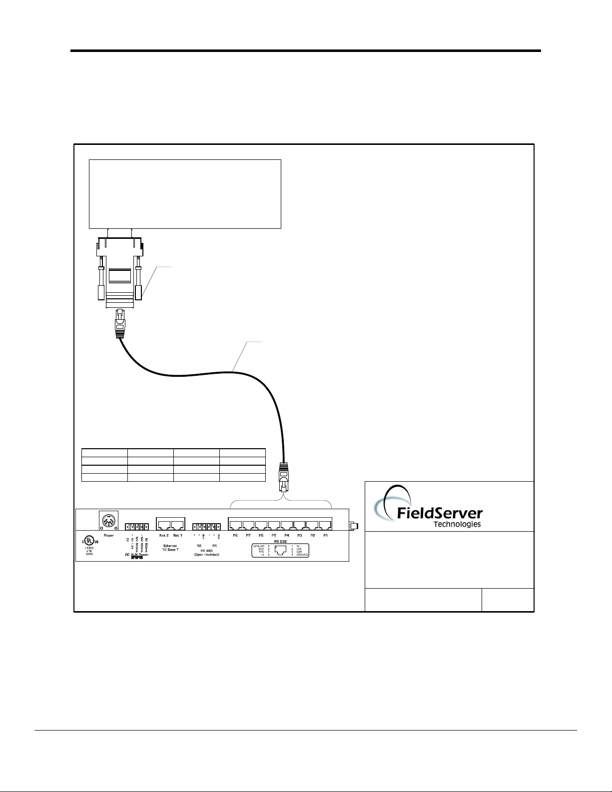
3. Hardware Connections
It is possible to connect an Allen Bradley PLC to any of the RS-232 ports. These ports simply
need to be configured for an Allen Bradley PLC in the configuration file.
ALLEN BRADLEY PLC
COMM 2
FS8917-06
RJ45 CAT 5 Cable
FS8915-10
8917-06 WIRE LIST
FUNCTION FROM TO COLOUR
Rx RJ45-01 DB9F-03 WHITE
GND RJ45-04 DB9F-05 GREEN
Tx RJ45-08 DB9F-02 BLUE
FIELDSERVER
DF1
CONNECTION DIAGRAM
BASE NAME:
FILE NAME:
(408)-262-2299
DATE: 4/20/04
BY: MC
FieldServer Technologies 1991 Tarob Court Milpitas, California 95035 USA Web:www.fieldserver.com
Tel: (408) 262-2299 Fax: (408) 262-2269 Toll_Free: 888-509-1970 email: support@fieldserver.com
Page 6
FS-8700-03 DF1 Driver Manual Page 6 of 16
4. Configuring the FieldServer as a DF1 Client
For a detailed discussion on FieldServer configuration, please refer to the FieldServer
Configuration Manual. The information that follows describes how to expand upon the factory
defaults provided in the configuration files included with the FieldServer (See “.csv” sample files
provided with the FS).
This section documents and describes the parameters necessary for configuring the FieldServer
to communicate with a DF1 Server
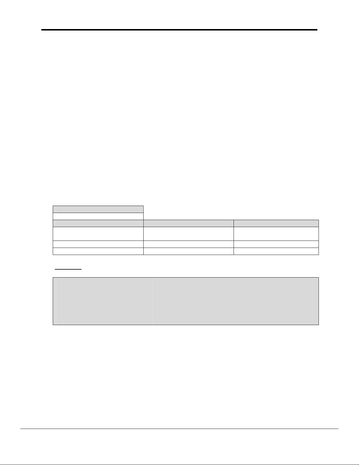
4.1. Data Arrays/Descriptors
The configuration file tells the FieldServer about its interfaces, and the routing of data
required. In order to enable the FieldServer for DF1 communications, the driver
independent FieldServer buffers need to be declared in the “Data Arrays” section, the
destination device addresses need to be declared in the “Client Side Nodes” section, and
the data required from the Servers needs to be mapped in the “Client Side Map Descriptors”
section. Details on how to do this can be found below.
Note that in the tables, * indicates an optional parameter, with the bold legal value being the
default.
Section Title
Data_Arrays
Column Title Function Legal Values
Data_Array_Name Provide name for Data Array
Data_Format Provides data format INT16, INT32, BIT, FLOAT
Data_Array_Length Number of Data Objects 1-10,000
Example
// Data Arrays
Data_Array_Name, Data_Format, Data_Array_Length
DA_AI_01, Float, 200
DA_AO_01, Float, 200
DA_DI_01, Bit, 200
DA_DO_01, Bit, 200
Up to 15 alphanumeric
characters
FieldServer Technologies 1991 Tarob Court Milpitas, California 95035 USA Web:www.fieldserver.com
Tel: (408) 262-2299 Fax: (408) 262-2269 Toll_Free: 888-509-1970 email: support@fieldserver.com
Page 7
FS-8700-03 DF1 Driver Manual Page 7 of 16
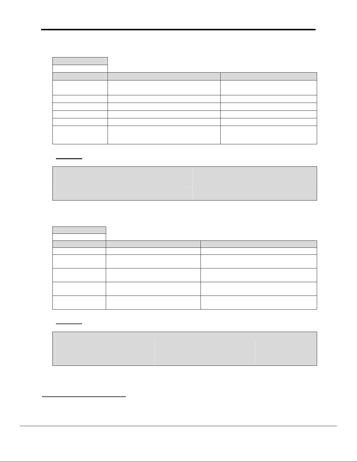
4.2. Client Side Connections
Section Title
Connections
Column Title Function Legal Values
Port
Baud* Specify baud rate
Parity* Specify parity
Data_Bits* Specify data bits
Handshaking*4 Specify hardware handshaking
Protocol * Specify protocol used
Example
// Client Side Connections
Ports,
Port, Protocol
P8, DF1_FD
Specify which port the device is
connected to the FieldServer
P1-P83
300 to 115200; 9600
Even, Odd, None
8
RTS, RTS/CTS, None
DF1_FD, DF1_HD_MASTER,
DF1_HD_SLAVE
4.3. Client Side Node Descriptors
Section Title
Nodes
Column Title Function Legal Values
Node_Name Provide name for node Up to 32 alphanumeric characters
Node_ID
Protocol Specify protocol used
Port
PLC_Type
Example
// Client Side Nodes
Nodes
Node_Name, Node_ID, Protocol, PLC _Type, Port
PLC_01, 1, DF1_FD, SLC5, P8
Node ID of physical Server node
(PLC)
Specify which port the device is
connected to the FieldServer
Specify PLC
Communications type.
1-255
DF1_FD, DF1_HD_MASTER,
DF1_HD_SLAVE
P1-P83
PLC3, PLC5, SLC5
3
Not all ports shown are necessarily supported by the hardware. Consult the appropriate Instruction
manual for details of the ports available on specific hardware.
4
Handshaking is not supported, only the enabling of the RTS/CTS lines
FieldServer Technologies 1991 Tarob Court Milpitas, California 95035 USA Web:www.fieldserver.com
Tel: (408) 262-2299 Fax: (408) 262-2269 Toll_Free: 888-509-1970 email: support@fieldserver.com
Page 8

FS-8700-03 DF1 Driver Manual Page 8 of 16
4.4. Client Side Map Descriptors
4.4.1. FieldServer Related Map Descriptor Parameters
Column Title Function Legal Values
Map_Descriptor_Name Name of this Map Descriptor
Name of Data Array where
Data_Array_Name
Data_Array_Offset Starting location in Data Array
Function
data is to be stored in the
FieldServer
Function of Client Map
Descriptor
Up to 32 alphanumeric
characters
One of the Data Array
names from “Data Array”
section above
0 to maximum specified in
“Data Array” section above
RDBC, WRBC, WRBX
4.4.2. Driver Related Map Descriptor Parameters
Column Title Function Legal Values
Node_Name
File_Type File type in PLC N, F, B, I, O5
File_Number File Number in PLC 0-255
Address Starting address of read block 0 – 255
Data_Array_Low_Scale* Scaling zero in Data Array
Data_Array_High_Scale* Scaling max in Data Array
Node_Low_Scale*
Node_High_Scale*
Name of Node to fetch data
from
Scaling zero in Connected
Node
Scaling max in Connected
Node
One of the node names
specified in “Client Node
Descriptor” above
-32767 to 32767, 0
-32767 to 32767, 100
-32767 to 32767, 0
-32767 to 32767, 100
5
Not all PLC’s can support all File_Types. Refer to DFS for further information.
FieldServer Technologies 1991 Tarob Court Milpitas, California 95035 USA Web:www.fieldserver.com
Tel: (408) 262-2299 Fax: (408) 262-2269 Toll_Free: 888-509-1970 email: support@fieldserver.com
Page 9

Tel: (408) 262-2299 Fax: (408) 262-2269 Toll_Free: 888-509-1970 email: support@fieldserver.com
FieldServer Technologies 1991 Tarob Court Milpitas, California 95035 USA Web:www.fieldserver.com
4.4.3. Map Descriptor Example
FS-8700-03 DF1 Driver Manual Page 9 of 16s
// Client Side Map Descriptors
Map_Descriptors
Map_Descriptor_Name, Data_Array_Name, Data_Array_Offset, Function, Node_Name, File_Type, File_Number, Address, Length, Scan_Interval
CMD_AI_01, DA_AI_01, 0, Rdbc, PLC_01, N, 10, 0, 16, 1.0s
CMD_AO_01, DA_AO_01, 0, Rdbc, PLC_01, N, 11, 0, 16, 1.0s
Map_Descriptors
Map_Descriptor_Name, Data_Array_Name, Data_Array_Offset, Function, Node_Name, File_Type, File_Number, Address, Length, Scan_Interval
CMD_DI_01, DA_DI_01, 0, Rdbc, PLC_01, B, 12, 0, 16, 1.0s
CMD_DO_01, DA_DO_01, 0, Rdbc, PLC_01, B, 13, 0, 16, 1.0s
Page 10

FS-8700-03 DF1 Driver Manual Page 10 of 16
5. Configuring the FieldServer as a DF1 Server
For a detailed discussion on FieldServer configuration, please refer to the FieldServer
Configuration Manual. The information that follows describes how to expand upon the factory
defaults provided in the configuration files included with the FieldServer (See “.csv” files on the
driver diskette).
This section documents and describes the parameters necessary for configuring the FieldServer
to communicate with a DF1 Client.
The configuration file tells the FieldServer about its interfaces, and the routing of data required.
In order to enable the FieldServer for DF1 communications, the driver independent FieldServer
buffers need to be declared in the “Data Arrays” section, the FieldServer virtual node(s) needs
to be declared in the “Server Side Nodes” section, and the data to be provided to the Clients
needs to be mapped in the “Server Side Map Descriptors” section. Details on how to do this
can be found below.
Note that in the tables, * indicates an optional parameter, with the bold legal value being the
default.
5.1. Server Side Connection Descriptions
Section Title
Connections
Column Title Function Legal Values
Port
Baud* Specify baud rate
Parity* Specify parity
Data_Bits* Specify data bits
Handshaking*
Protocol Specify protocol used
Specify which port the device is connected
to the FieldServer
7
Specify hardware handshaking
P1-P86
300 to 115200; 9600
Even, Odd, None
8
RTS, RTS/CTS, None
DF1_FD, DF1_HD_MASTER,
DF1_HD_SLAVE
Example
// Server Side Connections
Ports,
Port, Protocol
P1, DF1_FD
6
Not all ports shown are necessarily supported by the hardware. Consult the appropriate Instruction
manual for details of the ports available on specific hardware.
7
Handshaking is not supported, only the enabling of the RTS/CTS lines
FieldServer Technologies 1991 Tarob Court Milpitas, California 95035 USA Web:www.fieldserver.com
Tel: (408) 262-2299 Fax: (408) 262-2269 Toll_Free: 888-509-1970 email: support@fieldserver.com
Page 11
FS-8700-03 DF1 Driver Manual Page 11 of 16
5.2. Server Side Node Descriptions
Section Title
Nodes
Column Title Function Legal Values
Node_Name Provide name for node
Node_ID
Protocol Specify protocol used
PLC_Type
Node ID of physical Server
node
Specify PLC Communications
type.
Example
// Server Side Nodes
Nodes
Node_Name, Node_ID, Protocol, PLC _Type
DF1_Srv_11, 11, DF1_FD, SLC5
Up to 32 alphanumeric
characters
1-255
DF1_FD, DF1_HD_MASTER,
DF1_HD_SLAVE
PLC3, PLC5, SLC5
FieldServer Technologies 1991 Tarob Court Milpitas, California 95035 USA Web:www.fieldserver.com
Tel: (408) 262-2299 Fax: (408) 262-2269 Toll_Free: 888-509-1970 email: support@fieldserver.com
Page 12

FS-8700-03 DF1 Driver Manual Page 12 of 16
5.3. Server Side Map Descriptors
5.3.1. FieldServer Specific Map Descriptor Parameters
Section Title
Map_Descriptors
Column Title Function Legal Values
Map_Descriptor_Name Name of this Map Descriptor
Name of Data Array where
Data_Array_Name
Data_Array_Offset
Function
data is to be stored in the
FieldServer
Starting location in Data
Array
Function of Client Map
Descriptor
Up to 32 alphanumeric
characters
One of the Data Array
names from “Data Array”
section above
0 to maximum specified in
“Data Array” section above
Server
5.3.2. Driver Specific Map Descriptor Parameters
Section Title
Map_Descriptors
Column Title Function Legal Values
Node_Name
File_Type File type in PLC N, F, B, I, O8
File_Number File number in PLC 0-255
Address
Data_Array_Low_Scale* Scaling zero in Data Array
Data_Array_High_Scale* Scaling max in Data Array
Node_Low_Scale*
Node_High_Scale*
Name of Node to fetch data
from
Starting address of read
block
Scaling zero in Connected
Node
Scaling max in Connected
Node
One of the node names
specified in “Client Node
Descriptor” above
0 - 255
-32767 to 32767, 0
-32767 to 32767, 100
-32767 to 32767, 0
-32767 to 32767, 100
8
Not all PLC’s can support all File_Types. Refer to DFS for further information.
FieldServer Technologies 1991 Tarob Court Milpitas, California 95035 USA Web:www.fieldserver.com
Tel: (408) 262-2299 Fax: (408) 262-2269 Toll_Free: 888-509-1970 email: support@fieldserver.com
Page 13

Tel: (408) 262-2299 Fax: (408) 262-2269 Toll_Free: 888-509-1970 email: support@fieldserver.com
FieldServer Technologies 1991 Tarob Court Milpitas, California 95035 USA Web:www.fieldserver.com
5.3.3. Map Descriptor Example
FS-8700-03 DF1 Driver Manual Page 13 of 16
// Server Side Map Descriptors
Map_Descriptors
Map_Descriptor_Name, Data_Array_Name, Data_Array_Offset, Function, Node_Name, File_Type, File_Number, Address, Length, Data_Array_Low_Scale
CMD_AI_01, DA_AI_01, 0, Rdbc, PLC_01, N, 10, 0, 16, 1.0s
CMD_AO_01, DA_AO_01, 0, Rdbc, PLC_01, N, 11, 0, 16, 1.0s
Map_Descriptor_Name, Data_Array_Name, Data_Array_Offset, Function, Node_Name, File_Type, File_Number, Address, Length, Scan_Interval
CMD_DI_01, DA_DI_01, 0, Rdbc, PLC_01, B, 12, 0, 16, 1.0s
CMD_DO_01, DA_DO_01, 0, Rdbc, PLC_01, B, 13, 0, 16, 1.0s
Page 14

FS-8700-03 DF1 Driver Manual Page 14 of 16
Appendix A. Driver Notes
Appendix A.1. Continuous Map Descriptors
RS View has been known to crash if it tries to read a Server mapping that is discontinuous.
e.g. Server map 1: N21: 0-31
Server map 2: N21: 32-100
This will panic the FieldServer and crash RS view as the DF1 will attempt to map N21: 0-100
If set up as:
Server Map 1: N21: 0-100 No problems are experienced
Appendix A.2. Checksum
You can now specify a checksum parameter for the serial connection.
The heading keyword is "Checksum" and the possible values are
1) BCC or 2) CRC-16
If nothing is specified it defaults to BCC.
Example:
Connections
Port, Baud, Protocol, Checksum
P1, 9600, DF1_FD, CRC-16
The Checksum is valid for both DF1_FD and DF1_HD.
Appendix A.3. Command Support
The following commands are supported by the FieldServer for the various PLC types:
PLC_Type File_Type FNC Read FNC Write
N 1 Range Read 0 Range Write N7: 3, L5
PLC3
PLC5
SLC5
F 1 Range Read 0 Range Write F12: 3, L5
B 1 Range Read 2 Bit Write B3/4: 5, l5
N 1 Range Read 0 Range Write N7: 3 , L5
F 1 Range Read 67 Typed Write F12: 3, L5
B 1 Range Read 26 Read Modify Write B3/4: 5, L5
N A2/A1
F A2/A1
B A2/A1
I A2/A1
O A2/A1
Protected Typed
Logical Read
Protected Typed
Logical Read
Protected Typed
Logical Read
Protected Typed
Logical Read
Protected Typed
Logical Read
Protected Typed
AA
Logical Write
Protected Typed
AA
Logical Write
Protected Typed
AB
Logical Write
- - I: 13, L5
- - O: 13, L5
FieldServer Technologies 1991 Tarob Court Milpitas, California 95035 USA Web:www.fieldserver.com
Tel: (408) 262-2299 Fax: (408) 262-2269 Toll_Free: 888-509-1970 email: support@fieldserver.com
Typical
Command
N7: 3, L5
B3/4: 5, L7
B3/4: 5, L8
Page 15
FS-8700-03 DF1 Driver Manual Page 15 of 16
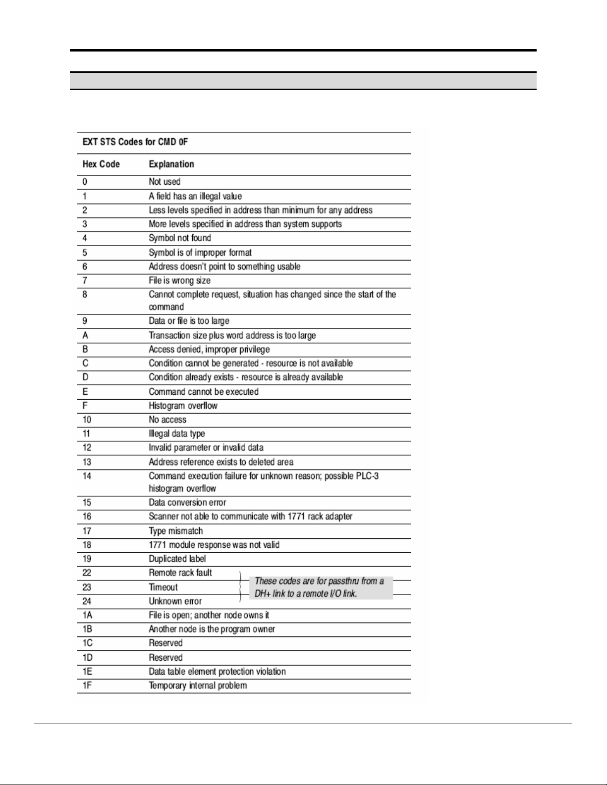
Appendix B. Error Messages
DF1 Rem STS err F0-> Extended error code [See table below]
FieldServer Technologies 1991 Tarob Court Milpitas, California 95035 USA Web:www.fieldserver.com
Tel: (408) 262-2299 Fax: (408) 262-2269 Toll_Free: 888-509-1970 email: support@fieldserver.com
Page 16

FS-8700-03 DF1 Driver Manual Page 16 of 16
THIS PAGE INTENTIONALLY LEFT BLANK
FieldServer Technologies 1991 Tarob Court Milpitas, California 95035 USA Web:www.fieldserver.com
Tel: (408) 262-2299 Fax: (408) 262-2269 Toll_Free: 888-509-1970 email: support@fieldserver.com
 Loading...