

Page 1

A Sierra Monitor Company
Driver Manual
(Supplement to the FieldServer Instruction Manual)
FS-8700-02 Modbus Plus
APPLICABILITY & EFFECTIVITY
Effective for all systems manufactured after May 1, 2001
Instruction Manual Part Number FS-8700-02
Version 1.00
Revision 1a
5/24/2002
Page 2

FS-8700-02 Modbus Plus Driver Manual
Table of Contents
1. Modbus Plus Description............................................................................................................. 1
1.1 Hardware/Software............................................................................................................... 1
2. FieldServer as a Modbus Plus Client ............................................................................................ 3
2.1 Hardware Connections .......................................................................................................... 3
2.2 Configuration File Structure................................................................................................... 3
2.2.1 Data Arrays .......................................................................................................................3
2.2.2 Client Side Connections ..................................................................................................... 3
2.2.3 Client Side Nodes ..............................................................................................................3
2.2.4 Client Side Map Descriptors ...............................................................................................4
3. FieldServer as a Modbus Plus Server............................................................................................ 5
3.1 Hardware Connections .......................................................................................................... 5
3.2 Configuration File Structure................................................................................................... 5
3.2.1 Data Arrays .......................................................................................................................5
3.2.2 Server Side Connections .................................................................................................... 5
3.2.3 Server Side Nodes............................................................................................................. 5
3.2.4 Server Side Map Descriptors.............................................................................................. 6
3.3 Examples of FieldServer setup for typical clients .................................................................... 6
FieldServer Technologies 1991 Tarob Court, Milpitas, California 95035 (408) 262-2299 fax: (408) 262-9042
Visit our website: www.fieldserver.com E-mail: support@fieldserver.com
Page Index
Page 3
FS-8700-02 Modbus Plus Driver Manual
1. Modbus Plus Description
The Modbus Plus driver allows the FieldServer to transfer data to and from devices using
Modbus Plus protocol. The FieldServer can emulate either a Server or Client.
The information that follows describes how to expand upon the factory defaults provided in the
configu ration files included with the FieldServer.
The FieldServer is shipped with the switches set of a default address of 11.
Set the Modbus Plus address switches 1--6 to the address in your application. Switches 7 and 8
are not used.
Switch 1 is the least significant bit of the address. Switch 6 is the most significant bit. The address
will be one higher than the binary value you set into the switches.
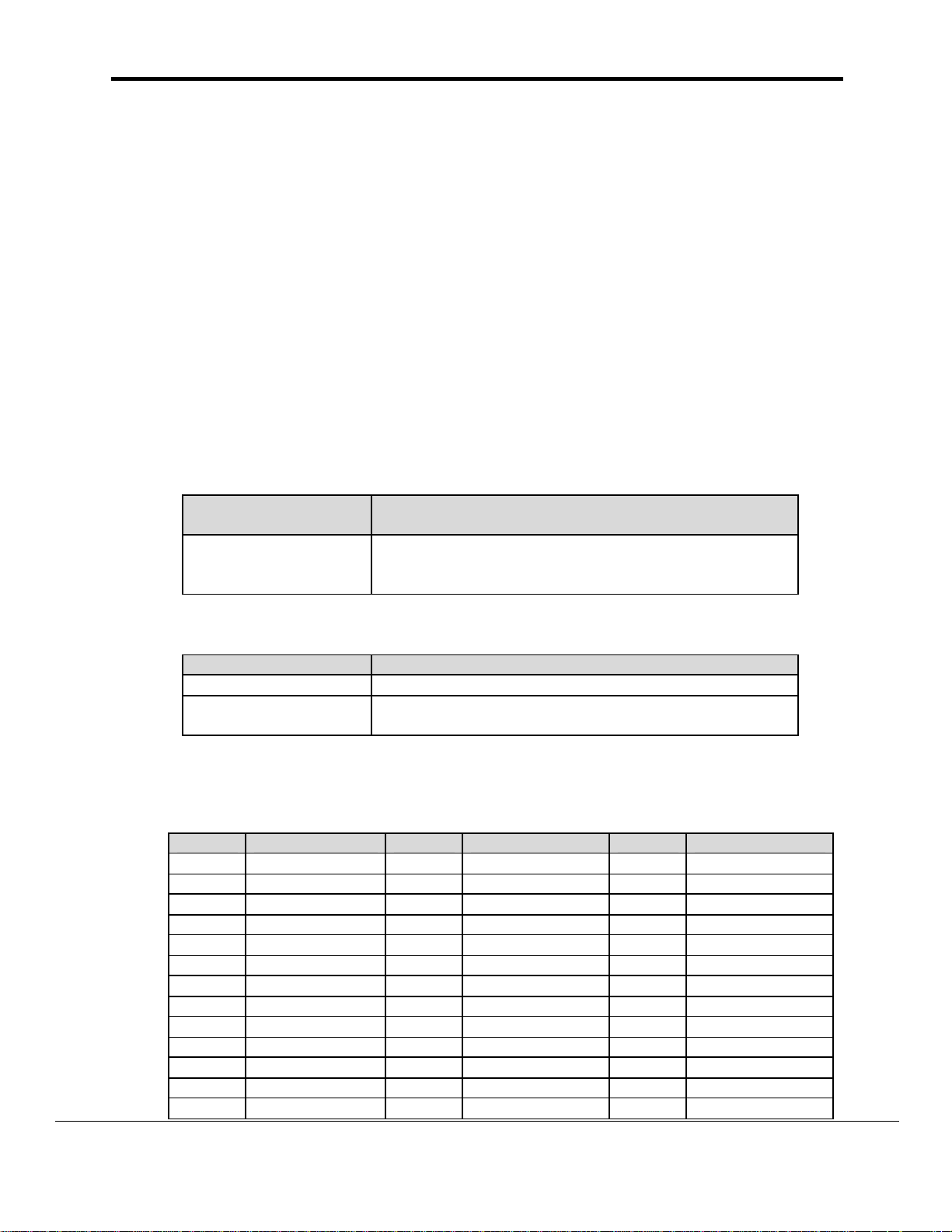
1.1 Hardware/Software
Supplied by FieldServer
FieldServer
DESCRIPTION
Technologies PART #
FS-8915-01 Adapter Card, Modbus Plus, Single Port. User must supply
Modbus Plus cables and connectors, including termination
connectors as documented by Group Schneider/Modicon
Provided by user
PART # DESCRIPTION
Refer to the Drawings in section 3
Modbus Plus Client, e.g. Wonderware, Intellution FIX, GE
Cimplicity, etc.
1
If FieldServer used as Modbus Plus Client.
2
If FieldServer used as Modbus Plus Server.
2
1
Table 1: Modbus Plus Addresses and Switch Settings
Address Switches 6--1 Address Switches 6--1 Address Switches 6--1
1 0 0 0 0 0 0 23 0 1 0 1 1 0 45 1 0 1 1 0 0
2 0 0 0 0 0 1 24 0 1 0 1 1 1 46 1 0 1 1 0 1
3 0 0 0 0 1 0 25 0 1 1 0 0 0 47 1 0 1 1 1 0
4 0 0 0 0 1 1 26 0 1 1 0 0 1 48 1 0 1 1 1 1
5 0 0 0 1 0 0 27 0 1 1 0 1 0 49 1 1 0 0 0 0
6 0 0 0 1 0 1 28 0 1 1 0 1 1 50 1 1 0 0 0 1
7 0 0 0 1 1 0 29 0 1 1 1 0 0 51 1 1 0 0 1 0
8 0 0 0 1 1 1 30 0 1 1 1 0 1 52 1 1 0 0 1 1
9 0 0 1 0 0 0 31 0 1 1 1 1 0 53 1 1 0 1 0 0
10 0 0 1 0 0 1 32 0 1 1 1 1 1 54 1 1 0 1 0 1
11* 0 0 1 0 1 0 33 1 0 0 0 0 0 55 1 1 0 1 1 0
12 0 0 1 0 1 1 34 1 0 0 0 0 1 56 1 1 0 1 1 1
13 0 0 1 1 0 0 35 1 0 0 0 1 0 57 1 1 1 0 0 0
FieldServer Technologies 1991 Tarob Court, Milpitas, California 95035 (408) 262-2299 fax: (408) 262-9042
Visit our website: www.fieldserver.com E-mail: support@fieldserver.com
Page 1
Page 4

FS-8700-02 Modbus Plus Driver Manual
Address Switches 6--1 Address Switches 6--1 Address Switches 6--1
14 0 0 1 1 0 1 36 1 0 0 0 1 1 58 1 1 1 0 0 1
15 0 0 1 1 1 0 37 1 0 0 1 0 0 59 1 1 1 0 1 0
16 0 0 1 1 1 1 38 1 0 0 1 0 1 60 1 1 1 0 1 1
17 0 1 0 0 0 0 39 1 0 0 1 1 0 61 1 1 1 1 0 0
18 0 1 0 0 0 1 40 1 0 0 1 1 1 62 1 1 1 1 0 1
19 0 1 0 0 1 0 41 1 0 1 0 0 0 63 1 1 1 1 1 0
20 0 1 0 0 1 1 42 1 0 1 0 0 1 64 1 1 1 1 1 1
21 0 1 0 1 0 0 43 1 0 1 0 1 0
22 0 1 0 1 0 1 44 1 0 1 0 1 1 * = default
Table 2: Summary of Modbus Data Access Commands
Function Code (Decimal) Command Name
1 Read Discrete Output Status (0xxxx)
2 Read Discrete Input Status (1xxxx)
3 Read Output Register (4xxxx)
4 Read Input Register (3xxxx)
5 Force Single Coil (0xxxx)
6 Preset Single Register (4xxxx)
15 Force Multiple Coils (0xxxx)
16 Preset Multiple Registers (4xxxx)
Modbus Plus Card Indicators
The Modbus Plus card has an indicator that flashes a repetitive pattern to show its network
communication status, plus two indicators which identify communication errors on the two
Modbus Plus cable paths. Note that one error indicator will be lit normally in single-cable
installations, showing that a second cable does not exist.
Table 3: Modbus Plus Active Indicator Patterns
Indicator Pattern (Green) Status
Six flashes/second Normal operating state. All nodes on a healthy
network flash this pattern
One flash/second The node is off-line. After being in this state for 5
seconds, the node attempts to go to its normal
operating state.
Two flashes, then OFF for 2
seconds
The node detects the network token being passed
among other nodes, but it never receives the
token.
Three flashes, then OFF for
1.7 seconds
Four flashes, then OFF for
1.4 seconds
The node does not detect any token passing on the
network.
The node has detected another node using the
same address.
FieldServer Technologies 1991 Tarob Court, Milpitas, California 95035 (408) 262-2299 fax: (408) 262-9042
Visit our website: www.fieldserver.com E-mail: support@fieldserver.com
Page 2
Page 5

FS-8700-02 Modbus Plus Driver Manual
2. FieldServer as a Modbus Plus Client
2.1 Hardware Connections
It is possible to connect a Modbus RTU device to any of the eight RS232 ports or two RS485
ports. These ports just need to be configured for Modbus RTU in the configuration file.
Configure the PLC according to manufacturer’s instructions.
2.2 Configuration File Structure
Refer to section 4.1 of the Instruction Manual for a description of the operation prin ciple
of the FieldServer. The following tables describe parameters that need to be filled out in
the configuration file. For convenience, a few example parameters already exist in the
supplied PRIMSERV.CSV and SECDSERV.CSV files.
Note that * indicates an optional parameter, with the bold legal value being the default.
2.2.1 Data Arrays
Section Title
Data_Arrays
Column Title Function Legal Values
Data_Array_Name Provide name for Data Array Up to 15
alphanumeric
characters
Data_Format Provides data format INT16, INT32, BIT,
FLOAT
Data_Array_Length Number of Data Objects 1-10,000
2.2.2 Client Side Connections
Section Title
Connections
Column Title Function Legal Values
Adapter Adapter name MBP
2.2.3 Client Side Nodes
Section Title
Nodes
Column Title Function Legal Values
Node_Name Provide name for node Up to 32
alphanumeric
characters
Route Modbus Plus Path Note 1*
Protocol Specify protocol used Modbus Plus
Note 1: Refer to the Modicon user guide 890 USE 102 00 for details on path
establishment. In general, the first number is the Destination BM85 MAC address,
the second number represents the internal path, and the third number is the
destination node. This varies if the BM85 is not connected to the FieldServer.
FieldServer Technologies 1991 Tarob Court, Milpitas, California 95035 (408) 262-2299 fax: (408) 262-9042
Visit our website: www.fieldserver.com E-mail: support@fieldserver.com
Page 3
Page 6

FS-8700-02 Modbus Plus Driver Manual
2.2.4 Client Side Map Descriptors
Section Title
Map_Descriptors
Column Title Function Legal Values
Map_Descriptor_Name Name of this Map Descriptor Up to 32
alphanumeric
characters
Data_Array_Name Name of Data Array where
data is to be stored in the
FieldServer
Data_Array_Offset Starting location in Data
Array
One of the Data Array
names from “Data
Array” section above
0 to maximum
specified in “Data
Array” section above
Function Function of Client Map
RDBC
Descriptor
Node_Name Name of Node to fetch data
from
One of the node
names specified in
“Client Node
Descriptor” above
Address Starting address of read block 40001, 30001, etc
Length Number of items to read 1 - 125
Data_Array_Low_Scale* Scaling zero in Data Array -32767 to 32767,
default 0
Data_Array_High_Scale* Scaling max in Data Array -32767 to 32767,
default 100
Node_Low_Scale* Scaling zero in Connected
Node
Node_High_Scale* Scaling max in Connected
Node
-32767 to 32767,
default 0
-32767 to 32767,
default 100
FieldServer Technologies 1991 Tarob Court, Milpitas, California 95035 (408) 262-2299 fax: (408) 262-9042
Visit our website: www.fieldserver.com E-mail: support@fieldserver.com
Page 4
Page 7

FS-8700-02 Modbus Plus Driver Manual
3. FieldServer as a Modbus Plus Server
3.1 Hardware Connections
Refer to the Drawings in section 4
Configure the Modbus Plus client according to manufacturer’s instructions (refer to
section below on examples of FieldServer setup for typical clients
3.2 Configuration File Structure
Refer to section 4.1 of the Instruction Manual for a description of the operation principle
of the FieldServer. The following tables describe parameters that need to be filled out in
the configuration file. For convenience, a few example parameters already exist in the
supplied PRIMSERV.CSV and SECDSERV.CSV files.
Note that * indicates an optional parameter, with the bold legal value being the default.
3.2.1 Data Arrays
SectionTitle
Data_Arrays
Column Title Function Legal Values
Data_Array_Name Provide name for Data Array Up to 15
alphanumeric
characters
Data_Format Provides data format INT16, INT32, BIT,
FLOAT
Data_Array_Length Number of Data Objects 1-10,000
3.2.2 Server Side Connections
Section Title
Connections
Column Title Function Legal Values
Adapter Adapter name MBP
Internal Path Modbus Plus data path 1 - 8
3.2.3 Server Side Nodes
Section Title
Nodes
Column Title Function Legal Values
Node_Name Provide name for node Up to 32
alphanumeric
characters
Node_ID Node ID of virtual server node 1 – 255
Protocol Specify protocol used Modbus Plus
FieldServer Technologies 1991 Tarob Court, Milpitas, California 95035 (408) 262-2299 fax: (408) 262-9042
Visit our website: www.fieldserver.com E-mail: support@fieldserver.com
Page 5
Page 8

FS-8700-02 Modbus Plus Driver Manual
3.2.4 Server Side Map Descriptors
Section Title
Map_Descriptors
Column Title Function Legal Values
Map_Descriptor_Name Name of this Map Descriptor Up to 32
alphanumeric
characters
Data_Array_Name Name of Data Array where
data is to be stored in the
FieldServer
Data_Array_Offset Starting location in Data
Array
One of the Data Array
names from “Data
Array” section above
0 to maximum
specified in “Data
Array” section above
Function Function of Client Map
Server
Descriptor
Node_Name Name of Node to fetch data
from
One of the node
names specified in
“Client Node
Descriptor” above
Address Starting address of read block 40001, 30001, etc
Length Number of items to read 1 - 125
Data_Array_Low_Scale* Scaling zero in Data Array -32767 to 32767,
default 0
Data_Array_High_Scale* Scaling max in Data Array -32767 to 32767,
default 100
Node_Low_Scale* Scaling zero in Connected
Node
Node_High_Scale* Scaling max in Connected
Node
-32767 to 32767,
default 0
-32767 to 32767,
default 100
3.3 Examples of FieldServer setup for typical clients
MSTR Example: Modbus Plus Node
This example shows a Modicon Modsoft screen for an MSTR function in a Modbus Plus
node. It writes one register of data to a virtual node in the FieldServer.
H The MSTR Function Code specifies a Write operation
H One register of data is to be transferred
H The destination register is 40000 (addressed as register 1).
H The FieldServer’s node address is 1. Note that the decimal value 1025
equals 0401 hexadecimal, addressing a Modbus Plus Network Option
Module (NOM) in backplane slot 04 and a node at address 01.
H The destination index is 28. The FieldServer will forward the message to
the TCP node whose IP address is in this location in the FieldServer’s TCP
Mapping table.
FieldServer Technologies 1991 Tarob Court, Milpitas, California 95035 (408) 262-2299 fax: (408) 262-9042
Visit our website: www.fieldserver.com E-mail: support@fieldserver.com
Page 6
Page 9

FS-8700-02 Modbus Plus Driver Manual
MSTR in Modbus Plus Node
FieldServer Technologies 1991 Tarob Court, Milpitas, California 95035 (408) 262-2299 fax: (408) 262-9042
Visit our website: www.fieldserver.com E-mail: support@fieldserver.com
Page 7
 Loading...