

Page 1

SAHARA
SYSTEM USER GUIDE
DOCUMENT No.:
PRODUCT PART No.:
MANUAL REVISION:
RELEASE DATE:
16399
25–10869–03
A2
August, 1998
Page 2

FCC NOTICE
CLASS B REGULATIONS
U. S. A.
FEDERAL COMMUNICATIONS COMMISSION RADIO FREQUENCY
INTERFERENCE STATEMENT
NOTE : This equipment has been tested and found to comply with the limits for
a Class B digital device pursuant to Part 15 of the FCC Rules. These
limits are designed to provide reasonable protection against harmful
interference in a residential installation. This equipment generates,
uses, and can radiate radio frequency energy and, if not installed and
used in accordance with the instructions, may cause harmful interference to radio communications. However, there is no guarantee that
interference will not occur in a particular installation. If this equipment
does cause harmful interference to radio or television reception, which
can be determined by turning the equipment off and on, the user is encouraged to try to correct the interference by one or more of the
following measures:
Reorient or relocate the receiving antenna.
Increase the separation between the equipment and receiver.
Connect the equipment into an outlet on a circuit different from that to
which the receiver is connected.
Consult the dealer or an experienced radio/TV technician for help.
Any changes or modifications not expressly approved by the manu-
facturer could void the user's authority to operate the equipment.
vii
Page 3

SAHARA System User Guide
CANADA
CANADIAN DEPARTMENT OF COMMUNICATIONS RADIO
INTERFERENCE REGULATIONS CLASS B COMPLIANCE NOTICE
This digital apparatus does not exceed the Class B limits for radio noise emissions from
digital apparatus set out in the Radio Interference Regulations of the Canadian Department of Communications.
Le présent appareil numérique n'émet pas de bruits radioélectriques dépassant les limites
applicables aux appareils numriques de la classe B prescrites dans le Réglement sur le
brouillage radioélectrique édicté par le ministére des Communications du Canada.
Legal Notice
Information are subject to change without notice. This manual is provided “as
is” without warranty of any kind, either express or implied, including but not
limited to the implied warranties or conditions of salability or fitness for a particular purpose. In no event shall we be liable for any loss of profits, loss of
business, loss of use or data, interruption of business, or for indirect, special,
incidental, or consequential damages of any kind, even if we have been advised
of the possibility of such damages arising from any defect or error in this manual or product. This manual may be revised from time to time without notice.
viii
Copyright © 1998, All Rights Reserved.
No part of this document, including the product and software may be reproduced, transmitted, transcribed, stored in a retrieval system, or translated into
any language in any form by any means without the express written permission
except documentation kept by the purchaser for backup purposes.
Products mentioned in this manual are mentioned for identification purposes
only. Product names appearing in this document may or may not be registered
trademarks or copyrights of their respective companies and owners. All rights
reserved.
Page 4

Trademarks
Intel and Pentium are registered trademarks of Intel Corporation. IBM is a registered trademark of International Business Machines Corporation. Microsoft,
MS-DOS, Windows, and Windows 95 are registered trademarks of Microsoft
Corporation.
FCC Notice
ix
Page 5

SAHARA System User Guide
— This Page Intentionally Left Blank —
x
Page 6
SAFETY INSTRUCTIONS
Battery Warning
WARNING : The computer is provided with a battery-powered real-time clock
circuit. There is a danger of explosion and risk of personal injury if
the battery is incorrectly replaced or mistreated. Do not attempt to
recharge the battery, disassemble it, remove it, immerse it in
water, or dispose of it in fire.
This computer has been tested for conformity to international safety regulations. Like any electronic device, however, the computer should be used with
care. To protect yourself from possible injury and to minimize the risk of damage to the computer, read and follow these safety instructions:
General Guidelines
n Read all of these instructions.
n Save these instructions for later use.
n Follow all warnings and instructions marked in the computer.
n Except as explained elsewhere in this manual, do not attempt to service the com-
puter yourself. Opening or removing these covers that are marked “Do Not Remove”
might expose you to dangerous voltage points or other risks. Refer all servicing of
marked compartments to a qualified personnel.
Installation Restrictions
n Do not use the computer near water.
n Do not place the computer on an unstable cart, stand, or table. The computer might
fall and be seriously damaged.
n Do not block or cover the ventilation slots on the cover or cabinet of the computer.
Air must be allowed to circulate through these slots in order to ensure that the computer operates properly and does not overheat.
n Install the computer near an electrical outlet for ease of access. Use the plug of the
power cord to disconnect power from the computer.
n Do not place the computer near or over a radiator or heat register or in direct sun-
light. Place the computer in a small enclosure only if proper ventilation is provided.
n Do not permit anything to rest on the power cord. Do not locate the computer where
people can walk on its power cord.
n Do not plug the computer into the same circuit with radio or television receivers.
i
Page 7
SAHARA System User Guide
n Wear a static wrist strap which fits around your wrist and is connected to a natural
earth ground.
n Touch a grounded or anti-static surface or a metal fixture such as a water pipe.
n Avoid contacting the components on add-on cards, boards and modules and the
“gold finger” connectors plugged into the expansion slot. It is best to handle system
components by their mounting bracket.
Electrical Restrictions
WARNING : This equipment is designed for connection to a grounded
(earthed) outlet. The grounding type plug is an important safety
feature. To reduce the risk of electrical shock, damage to your
equipment, or loss of your data, do not disable this feature.
Power Cord Set Requirements
The power cord set (appliance coupler, flexible, and wall plug) you received with
your computer meets the requirements for use in the country where you purchased
your equipment.
Power cord sets for use in other countries must meet the requirements of the country
where you use the computer. For more information on power cord set requirements,
contact your FIC authorized dealer, reseller, or service provider.
General Requirements
The requirements listed below are applicable to all countries:
1. The length of the power cord set must be at least 6.00 feet (1.8 m) and a maximum
of 9.75 feet (3.0 m).
2. All power cord sets must be approved by an acceptable accredited agency responsi-
ble for evaluation in the country where the power cord set will be used.
3. The power cord set must have a minimum current capacity of 10A and a normal
voltage rating of 125 or 250 volts AC, as required by each country’s power system.
4. The appliance coupler must meet the mechanical configuration of an EN 60
320./IEC 320 Standard Sheet C13 connector, for mating the appliance inlet on the
computer.
ii
Page 8
Safety Instructions
Country-Specific Requirements
Power Cord Set Requirement
Country Accredited Agency Applicable Note Numbers
Australia EANSW 1
Austria OVE 1
Belgium CEBC 1
Canada CSA 2
Denmark DEMKO 1
Finland FIMKO 1
France UTE 1
Germany VDE 1
Italy IMQ 1
Japan JIS 3
The Netherlands KEMA 1
Norway NEMKO 1
Sweden SEMKO 1
Switzerland SEV 1
United Kingdom BSI 1
United States UL 2
NOTE:
1. Flexible cord must be <HAR> Type HO5VV-F, 3-conductor. 1.0 mm2 conductor size.
Power cord set fittings (appliance coupler and wall plug) must bear the certification mark
of the agency responsible for evaluation in the country where it will be used.
2. Flexible cord must be Type SVT or equivalent. NO. 18 AWG, 3-conductor. Wall plug
must be a two-pole grounding type with a NEMA 5-15P (15A. 125V) or NEMA 6-15P
(15A 250V) configuration.
3. Appliance coupler, flexible cord, and wall plug must bear a “T” mark and registration
number in accordance with the Japanese Dentori Law. Flexible cord must be Type VCT or
VCTF, 3-conductor, 0.75mm2 conductor size. Wall plug must be a two-pole grounding
type with a Japanese Industrial Standard C8303 (15A, 125V) configuration.
iii
Page 9
SAHARA System User Guide
Battery (Lithium)
NOTE : The following caution statement is located in the service and operating
manual or adjacent the battery.
1. English
"CAUTION: DANGER OF EXPLOSION IF BATTERY IS INCORRECTLY
REPLACED. REPLACE ONLY WITH SAME OR EQUIVALENT
TYPE RECOMMENDED BY THE MANUFACTURER. DISCARD
USED BATTERIES ACCORDING TO THE MANUFACTURER'S
INSTRUCTIONS"
2. French
IL Y A DANGER D'EXPLOSION S'IL Y A REMPLACEMENT INCORRECT DE
LA BATTERIE. REMPLACER UNIQUEMENT A VEC UNE BATTERIE DU
MÊME TYPE OU D'UN TYPE RECOMMANDÉ PAR LE CONSTRUCTER.
METTER AU RÉBUT LES BATTERIES USAGÉES CONFORMÉMENT AUX
INSTRUCTIONS DU FABRICANT"
3. German
"VORSICHT ! Explisionsgefahr bei unsachgemäßen Austausch der Batterie.
Ersatz nur durch denselben oder einem vom Hersteller empfohlenem ähnlichen Typ.
Entsorgung gebrauchter Batterien navh Angaben des Herstellers.
4. Swedish
“ Explosionsfara vid felaktigt batteribyte. Använd samma batterityp eller en
ekvivalent typ som rekommenderas av apparattillverkaren. Kassera använt
batteri enligt fabrikantens instruktion. “
(If the battery is placed in an area not accessible to the user even English text
can be used.)
5. Danish
“ Lithiumbatteri- Eksplosionsfare ved fejlagtig håndtering. Udskiftning må kum
ske med batteri af samme fabrikat og type. Lever det brugte batteri tilbage til
leverandoren. “
(The size of the warning must be a minimum of 26x52 mm., the background
shall be yellow color with black frame, and the text in black color. A white
background is acceptable in the User’s instruction and in the Service Manual.)
6. Norwegian
iv
Page 10
Safety Instructions
“ Ekspolsjonsafe ved feilaktig skifte av batteri. Benytt samme batteritype eller
en tilsvarende type anbefalt av apparatfabriknten. Brukte batterier kasseres i
henhold til fabrikantens instruksjoner. “
(Danish or Swedish text can also be accepted.)
(If the battery is placed in an area not accessible to the user even English text
can be used.)
7. Finnish
“ Paristo voi räjähtää, jos se on virheellisesti asennettu. Vaihda paristo ainostaan laitevalmistajan suosittelemaan tyyppiin. Hävitä käyteet paristo
valmistajan ohjeiden mukaisesti. “
(If the battery is placed in an area accessible to the user, the warning text has
to be both in Swedish and Finnish.)
(If the battery is placed in an area not accessible to the user, even Swedish or
English text can be used.)
Operating and Maintenance Guidelines
n Never spill liquids or push objects of any kind into the computer through cabinet
slots. Liquids and foreign objects might touch dangerous voltage points or short out
parts, creating a risk of fire or electrical shocks.
n Keep the area around the computer free from static electricity and magnetic fields.
Before you touch the computer, discharge static electricity on your body by touching
a metallic surface.
n Operate the computer only when the cover is in the closed position.
n Do not turn the computer on and off in rapid succession. Doing so might damage
data in the configuration files and on the hard fixed disk drive.
n Adjust only those controls that are covered by the operating instructions. Improper
adjustment of other controls might result in damage and often requires extensive
work by a qualified technician to restore the product to normal operation.
n Clean the display and computer periodically with a damp cloth. Do not use liquid or
aerosol cleanser. Unplug the computer from its electrical outlet before cleaning it.
n Prepare the computer before moving it by taking the following actions:
– Lock the cabinet cover.
– Insert an old diskette in each floppy diskette drive.
– Disconnect external peripheral devices.
v
Page 11

SAHARA System User Guide
n Unplug the computer from the wall outlet and refer servicing to qualified service
personnel under any of the following conditions:
– The cord or plug is damaged or frayed.
– Liquid has been spilled into the computer.
– The computer has been exposed to rain or water.
– The computer does not operate normally even when the operating instructions are
followed.
– The computer has been dropped or the cabinet has been damaged.
– The computer exhibits a distinct change in performance, indicating a need for
servicing.
vi
Page 12

TABLE OF CONTENTS
CHAPTER 1 Getting Started
Introduction to the SAHARA System......................................................... 1
Unpacking the SAHARA System................................................. 2
Item Checklist............................................................................... 3
Setting Up the SAHARA System ............................................................... 3
A Look at the Front the Computer.............................................................. 5
Attaching the Rubber Foot Set..................................................... 6
A Look at the Rear of the Computer........................................................... 6
Rear of the SAHARA System....................................................... 7
Display........................................................................................................ 9
General Features........................................................................... 9
2D Acceleration............................................................................ 9
3D Acceleration............................................................................ 10
Motion Video Acceleration.......................................................... 10
Software Support.......................................................................... 11
Display Capabilities ..................................................................... 12
Audio.......................................................................................................... 13
Features........................................................................................ 13
Ethernet PCI Bus (LAN) ............................................................................ 14
Features........................................................................................ 14
CHAPTER 2 Getting Ready to Go
Introduction................................................................................................ 15
System Connections ................................................................................... 15
Operating System........................................................................................ 16
Diskless LAN Station Setup....................................................................... 17
Power-On Operations................................................................................. 17
Diskette Operations .................................................................................... 18
Inserting/Removing Diskettes ...................................................... 18
Diskette Types.............................................................................. 19
Backing Up Master Diskettes....................................................... 19
Resetting the Computer .............................................................................. 20
Power-Off Operations................................................................................. 20
xi
Page 13

SAHARA System User Guide
CHAPTER 3 Making Upgrades Easy
Before You Begin....................................................................................... 23
Removing the Chassis Cover........................................................ 24
Removing the Front Panel Chassis............................................... 26
Installing the Hard Disk Drive (HDD) ......................................... 27
Installing the CD-ROM Drive...................................................... 32
Re-installing the Chassis Cover.................................................... 37
CHAPTER 4 BIOS Setup
Main CMOS Setup..................................................................................... 40
Load Defaults............................................................................... 40
Standard CMOS Setup ............................................................................... 41
Auto Detection of Hard Disks on Bootup .................................... 42
BIOS Features Setup .................................................................................. 44
Chipset Features Setup ............................................................................... 46
Power Management Setup.......................................................................... 47
PNP/PCI Configuration Setup.................................................................... 51
Load BIOS Defaults ................................................................................... 53
Load Setup Defaults ................................................................................... 53
Integrated Peripherals................................................................................. 54
Supervisor Password and User Password................................................... 56
IDE HDD Auto Detection .......................................................................... 56
Save and Exit Setup.................................................................................... 57
Exit Without Saving ................................................................................... 58
CHAPTER 5 Troubleshooting
Determining Problem Causes ..................................................................... 59
BIOS-Related Errors................................................................................... 60
APPENDIX A System Specifications
Product Features......................................................................................... 63
Technical Specifications............................................................................. 64
xii
Page 14

Table of Contents
APPENDIX B Installation Procedures
1). Set System Jumpers............................................................................... 66
Components That Concern Installation........................................ 67
CMOS Clear: CMOS_CLR.......................................................... 69
Flash ROM Type Select: EP1, EP2.............................................. 69
2). Install RAM Modules............................................................................ 70
SDRAM........................................................................................ 70
RAM Module Configuration........................................................ 70
Install DIMMs.............................................................................. 71
Remove DIMMs........................................................................... 72
3). Install the Central Processing Unit (CPU)............................................. 72
CPU Cartridge and Heatsink with Fan Installation
(for Pentium® II CPU)................................................................. 72
CPU and Passive Heatsink Installation (for Celeron™ CPU)...... 74
CPU to Bus Frequency Ratio: FREQ........................................... 75
Intel Pentium® II CPUs............................................................... 75
4). Install Expansion Cards......................................................................... 75
5). Connect Cables and Power Supply ....................................................... 79
Connectors.................................................................................... 79
Serial Port Connectors: COM1, COM2................................. 79
PS/2 Keyboard and Mouse Connector: MS, KB.................... 80
Printer Connector: LPT.......................................................... 80
Universal Serial Bus Connector: USB ................................... 81
Audio Port Connectors: LINE_OUT, LINE_IN, MIC_IN..... 81
RJ45 Connector: LAN ........................................................... 82
Infrared Connector: IR (optional) .......................................... 82
VGA Connector: VGA........................................................... 83
Joystick/MIDI Connector: GAME......................................... 83
CPU Fan Connector: CPU_FAN ........................................... 84
Floppy Diskette Drive Connector: FDD ................................ 85
IDE HDD Device Connector: PRIMARY ............................. 86
Hard Disk Drive Power Connector: HDD_PW...................... 86
CD-ROM Drive Connector: CD_ROM ................................. 87
Front Panel Block Connector: F_PNL................................... 87
ATX Power Connector: AT_PWR......................................... 88
APPENDIX C Driver Utilities
xiii
Page 15

SAHARA System User Guide
Starting Installation .................................................................................... 89
LANDesk® Client Manager (optional) ...................................................... 89
Two Options of the LDCM Setup.......................................... 89
Desktop Management Interface (DMI)....................................................... 90
Starting DMI.......................................................................... 90
Intel PIIX IDE Bus Master Driver.............................................................. 92
BIOS Flash Software.................................................................................. 92
VGA Display Drivers ................................................................................. 93
Audio Drivers............................................................................................. 93
CD-ROM Drive Software Drivers (optional) ............................................. 93
LAN Controller Driver............................................................................... 94
Setup Procedures for Diskless LAN Station .......................... 94
xiv
Page 16

Chapter 1
GETTING STARTED
Introduction to the SAHARA System
The unique design of the SAHARA System combines state-of-the-art electronics
with a sophisticated compact form factor to provide you with a smaller personal
computer that is both fast and powerful. Defining the next-generation of corporate
computing, the SAHARA System integrates the high-performance of an Intel
Pentium® II CPU and enhanced IDE hard disk drive to provide extra processing
power as well as the high-speed data access you need to handle all your computing
requirements. The use of integrated input/output connectors results in reduced
emissions and more input/output space at the rear.
The SAHARA System can be customized to perform a vast array of data transfer and
simplified networking tasks. The SAHARA system not only employs the latest
breakthroughs in personal computing technology but also complies with accepted
industry standards for maximum compatibility. And with its integrated management
technology, the SAHARA System allows centralized control of diagnostics and
upgrades across the network, significantly lowering maintenance costs.
The SAHARA System’s ultra-slim profile hides a revolutionary mainboard that
packs in powerful multimedia performance including AGP for fast 3D graphics
performance, soft DVD support, and 3D Sound Blaster Pro™ compatible audio,
allowing you to take advantage of the fascinating world of multimedia education and
home entertainment. Choose from hundreds of interactive CD-ROM titles and watch
a vivid, colorful world open up before your eyes, allowing you to enjoy high quality
audio with all your games, applications, and digital recordings. It also has a Line-In
port, a Speaker-Out port and an External Microphone port allowing you to use a wide
variety of audio software.
1
Page 17

SAHARA System User Guide
The SAHARA System not only employs the latest breakthroughs in personal
computing technology but also complies with accepted international safety,
regulatory and ergonomic standards for maximum compatibility.
The SAHARA System comes with two serial ports, two USB ports, one parallel port
with ECP/EPP, one Audio connector (Line-In, Line-Out, MIC-In), one RJ45 LAN
connector, two PS/2 connectors, one D-sub 15-pin female VGA port, one
Game/MIDI port (optional), one IrDA port (optional), and two expansion slot
openings, allowing you to connect your computer to a wide variety of input-output
devices such as mice, printers, modems, and graphics tablets. This User Guide is
provided to help you get the most out of your new investment. It describes all the
features of the SAHARA System in an easy-to-read yet thorough manner. The
primary goals of this chapter are (1) to introduce the computer’s features and (2) to
identify the computer’s external components. The chapter begins with instructions for
unpacking your new SAHARA System.
Unpacking the SAHARA System
Before unpacking the SAHARA System, prepare a suitable workspace for your
computer. Provide a steady, level and clean surface, near an electrical wall outlet. If
you are using a Fax/Modem, make sure that the workspace is located near a
telephone jack. Also ensure that the computer has enough space around it to allow for
airflow, especially at the rear of the computer near the fan. If the computer does not
have enough ventilation, internal components can become overheated and may
become damaged.
Using a computer for extended periods of time, a poor
workstation set-up, and incorrect work habits can create health
problems. The science of ergonomics studies the relationship
between health and a suitable work environment. For more
information on ergonomics, contact your nearest computer
bookstore, or local library.
When opening the box for your computer, make sure that you do not damage the box.
You may need it in the future for shipping or storing your SAHARA System.
When you have unpacked your computer, make sure the following items are included
in the box and are in good condition. If you find that any of these items are missing
or appear damaged, contact your SAHARA System dealer immediately.
2
Page 18

Chapter 1 - Getting Started
Item Checklist
þ SAHARA System Unit
þ AC Power Cord
þ one IDE Ribbon Cable
þ one IDE Power Cord
þ one CD-ROM Drive Ribbon Cable
þ one CD-ROM Drive Connector Adaptor
þ Heatsink with Fan (for system using Pentium® II or Mendocino™ CPU)
or Passive Heatsink (for system using Celeron™ CPU)
þ Screw Kit
þ This User’s Manual
þ Support Drivers and Utilities CD-ROM Disc
þ System Stand Foot Set
þ Rubber Foot Set
Remove the items from the shipping carton and protective packaging. Do not throw
away the packing material or shipping carton in case you need to ship or store the
components of the computer for future use.
Setting Up the SAHARA System
Place the computer system in a site that is clean, well-ventilated and near a grounded
(three-pronged) outlet. If the computer does not have enough ventilation, internal
components may overheat and become damaged. If you are using a Fax/Modem make
sure the workspace is near a telephone jack.
If the line voltage in your area is unreliable, you may want to
use a voltage regulator to protect the system from possible
harmful effects caused by sudden electrical surges.
Although the computer system is designed and built to work and last for a long time,
you may do well to heed the following precautions to get the most out of the system:
3
Page 19
SAHARA System User Guide
n Avoid placing the system on an unstable stand or surface subject to bumps
and violent shaking.
n Avoid food, smoke, or traffic areas that may expose the system to liquid
and food spills, cigarette ashes and dust.
n Do not subject the system to extreme temperatures and humidity.
n Occasionally clean the computer with a soft cloth moistened with water.
Do not use soap or liquid cleaners on the display monitor.
Unless you are a qualified technician, never tinker with any of
the components inside the system unit, display monitor and
keyboard. Irresponsible use of the system will invalidate the
warranties and may cause you unnecessary harm.
4
Page 20
Chapter 1 - Getting Started
In order to save valuable working space on your desktop, it is
advised that the system be placed in a vertical position as
opposed to the horizontal position.
In case system will be placed flat on a horizontal position,
attached the Rubber Foot Set to the system chassis cover (see
section on Attaching the Rubber Foot Set on the following
page) and make sure that the system cover’s ventilation air
holes are not blocked (e.g., display monitor, paper, etc.) and
that the computer has enough space around it to allow for
airflow, especially at the rear of the computer near the fan. If
the computer does not have enough ventilation, internal
components can become overheated and may be damaged.
A Look at the Front of the Computer
Refer to the following illustration to identify components located at the front of the
SAHARA System.
5
Page 21
SAHARA System User Guide
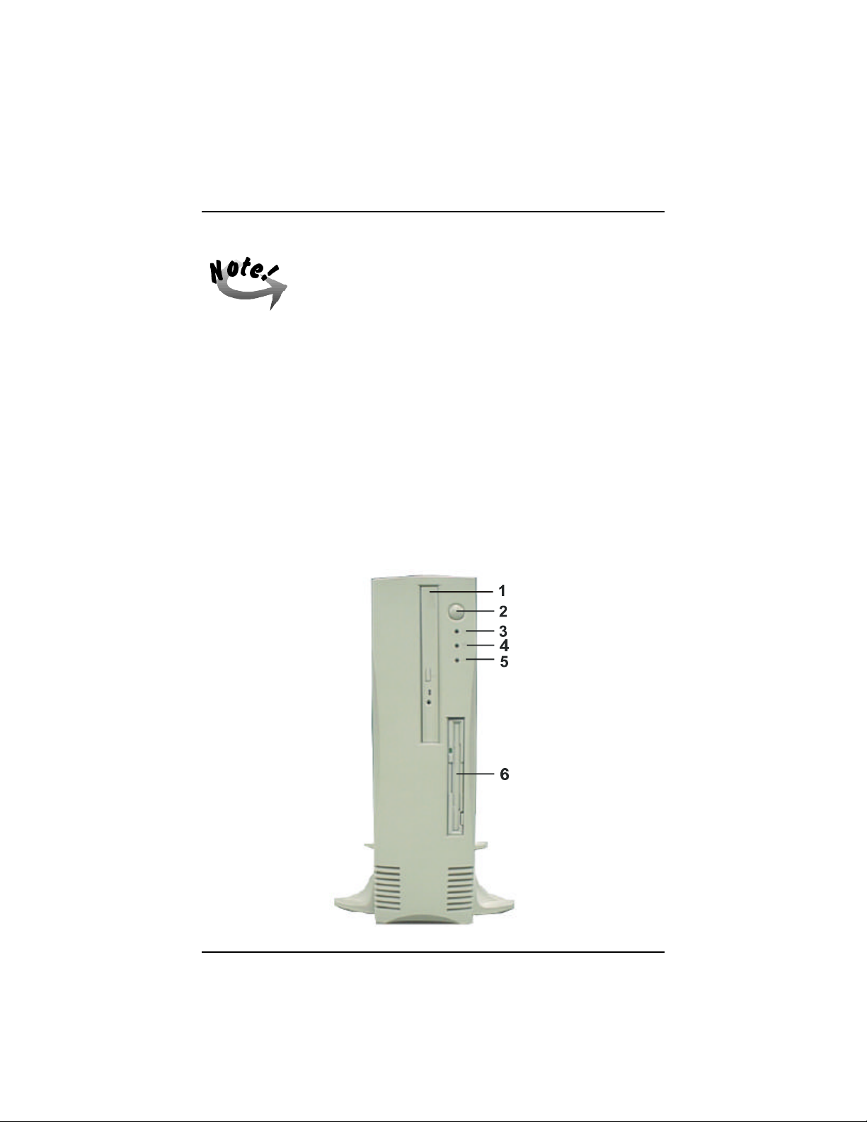
1. 12.7mm Slim CD-ROM Drive
The CD-ROM drive is located near the top of the SAHARA System.
2. Power Button
Press this button to turn on and off and reset your computer.
3. Power LED
When this green LED is lit, it indicates that system power is on.
4. Hard Disk Drive Access LED
When lit this green LED indicates that the hard disk drive (HDD) is being
accessed.
5. LAN Active LED
When lit this amber LED indicates that the system is currently online or
connected to the Network.
6. Floppy Disk Drive
The 3½” slim floppy disk drive (FDD) unit is located below the CD-ROM
drive.
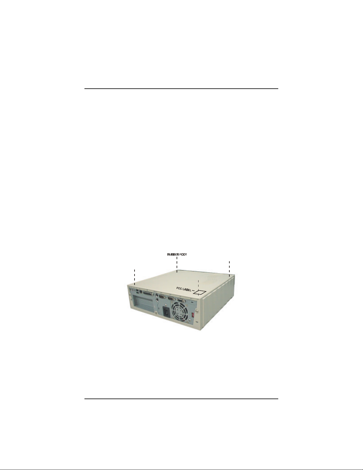
Attaching the Rubber Foot Set
Attach the four rubber foot set by peeling it off from the backing tape and sticking it
on the four indentations found on the system chassis cover.
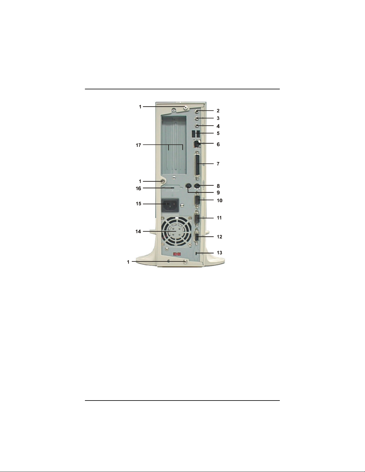
A Look at the Rear of the Computer
The rear of the SAHARA System is where you connect power, peripheral devices
such as a Fax/Modem or printer, input devices such as a PS/2 keyboard, and output
devices such as your display monitor. Refer to the following for an explanation of
each of the rear components:
6
Page 22
Chapter 1 - Getting Started
Rear of the SAHARA System
1. Rear Panel Screws
Use a Philips screwdriver to remove the three rear panel screws and turn
counter clockwise to release the chassis cover.
2. Microphone Jack
Plug the microphone to this jack for inputing voice.
3. Line-In Jack
This socket allows tape players or other audio sources to be recorded by
your computer or played through the Line-Out jack.
4. Line-Out Jack
Connect audio devices, such as a speaker to this port.
7
Page 23

SAHARA System User Guide
5. USB Ports
Provides fast and convenient Plug and Play peripheral connections outside
your computer, allowing you to take full advantage of the universal functionality and flexibility of USB technology. Connect a USB hub to these
ports.
6. RJ45 LAN Cable Socket
The LAN cable is plugged into this socket.
7. Parallel Port
This connector allows the system to link with a parallel device such as a
printer through a printer cable.
8. PS/2 Keyboard Connector
This connector is used to connect the PS/2 keyboard to the system.
9. PS/2 Mouse Connector
This connector is used to connect the PS/2 mouse to the system.
10. COM2 Port
Allows the connection of devices that take serial ports such as a modem. It
is recommended to connect your serial mouse to the COM1 port and your
fax/modem to the COM2 port.
11. COM1 Port
Allows the connection of devices that take serial ports such as a serial
mouse.
12. VGA Port
Connect the display monitor to this port.
13. IrDA Port (future option)
Connect the IR device to this port.
14. Power Supply Fan
This fan is used to cool the AC power supply. Ensure that there is free air
flow around the cooling fan.
15. AC-In Socket
Connect the computer’s AC power cord to this socket. Ensure that the
power cord is connected to a stable AC power source.
16. Game Port (future option)
Connect the joystick to this port.
17. Adapter Panel
Behind this panel is the expansion slot where an adapter or add-on card
can be installed.
8
Page 24

Chapter 1 - Getting Started
Display
The system comes with an integrated AGP-based ATI RAGE IIC/PRO AGP
controller chip. This VGA controller offers output pixel data rates with noninterlaced screen resolutions of up to 1600x1200x65k colors at a refresh rate of 76Hz
(2MB SGRAM upgradable to 8MB). The AGP controller enables the system to have
a higher performance under Windows and other GUI (Graphics User Interface)
environments, plus optimizations which result in even more impressive 2D and 3D
performance.
The RAGE IIC/PRO delivers 3D performance unmatched in its class, along with a
comprehensive list of 3D features including perspectively correct texturing, mipmapping, bilinear and trilinear filtering, z-buffering, video texturing, Gouraud
shading, and alpha blending.
The RAGE IIC/PRO incorporates excellent video support, suitable for MPEG-2
content and video conferencing acceleration. In addition to offering increased
performance and design flexibility, the RAGE IIC/PRO adds full PCI Power
Management support.
General Features
n PCI version 2.1 with full bus mastering and scatter/gather support
n Fully PC97 and PC98 compliant
n Full power management including PCI Power Management registers
n Triple 8-bit palette DAC with gamma correction for true WYSIWYG
color. Pixel rates up to 200MHz
n Supports DRAM, EDO DRAM (including single-cycle operation),
SDRAM and SGRAM across a 64-bit interface at up to 83MHz
n Supports block write feature of SGRAM for improved performance
n Integrated hardware diagnostic tests performed automatically upon initiali-
zation
2D Acceleration
n Hardware acceleration of Bitblt, Line Draw, Polygon/Rectangle Fill, Bit
Masking, Monochrome Expansion, Panning/Scrolling, Scissoring, full
ROP support and hardware cursor
9
Page 25

SAHARA System User Guide
n Game acceleration (including support for Microsoft’s DirectDraw): Dou-
ble Buffering, Virtual Sprites, Transparent Blit, Masked Blit and Context
Chaining
n Acceleration in 8/16/24/32 bpp modes. Packed pixel support (24bpp) en-
ables true color in 1MB configurations
3D Acceleration
n Complete 3D primitive support: points, lines, triangles, lists, strips and
quadrilaterals and BLTs with z compare
n Comprehensive enhanced 3D feature set:
• Full screen or window double buffering for smooth animation
• Hidden surface removal using 16-bit z-buffering
• Sub-pixel and sub-texel accuracy
• Gouraud and specular shaded polygons
• Perspectively correct mip-mapped texturing with chroma-key support
• Support for single pass bi- and tri-linear texture filtering
• Full support for Direct3D texture lighting
• Special effects such as complete alpha blending, fog, video textures
and texture lighting
• Dithering support in 16bpp for near 24bpp quality in less memory
n Extensive 3D mode support
Motion Video Acceleration
n Smooth video scaling and enhanced YUV to RGB color space conversion
for full-screen/full-speed video playback
n True colour overlay accepts video streams at full MPEG-2 width, up to
720 pixels
n Supports multi-stream video for video conferencing and other applications
n Filtered horizontal and vertical, up and down scaling enhances playback
quality
n Special filter circuitry eliminates video artifacts caused by displaying in-
terlaced video on non-interlaced displays
n Intercast capable video capture interface
10
Page 26

n Bus master engine includes bi-directional planar YUV to packed format
converter for superior MPEG playback and video conferencing acceleration
n Hardware mirroring for flipping video images in video conferencing sys-
tems
n Supports graphics and video keying for effective overlay of video and
graphics
n YUV to RGB color space converter with support for both packed and pla-
nar YUV
Software Support
n Register-compatible with VGA standards, BIOS-compatible with VESA
Super VGA
n Full-featured, yet simple Windows utilities:
• ATI DeskTop supports panning and scrolling across a virtual work-
space
• Calibration utility for WYSIWYG color
n Drivers meet Microsoft’s rigorous WHQL criteria and are suitable for
systems that bear the “Designed for Windows NT and Windows 95” logo
Chapter 1 - Getting Started
11
Page 27
SAHARA System User Guide
Software DOS Win 3.x Win 95 Win NT Mac OS OS/2
1
Accelerated driver VESA
2D Software Support
2
4 4 4 4 4
Video Software Support
Microsoft DirectDraw
Microsoft ActiveMovie
MPEG-1 software
4 4 4
4
4
playback
MPEG-2 software
4
playback
3D Software Support
Microsoft Direct3D
QuickDraw 3D RAVE
3
OpenGL
Heidi
ATI 3D CIF
4
4
4 4 4
4 4
4
4
NOTES:
1 - Additional 3rd parties (including SCO Unix and UNIXWARE)
2 - Direct BIOS support
3 - Includes NT 3.51 CD and NT 4.0 MCD
4 - ATI 3D API for the 3D RAGE family
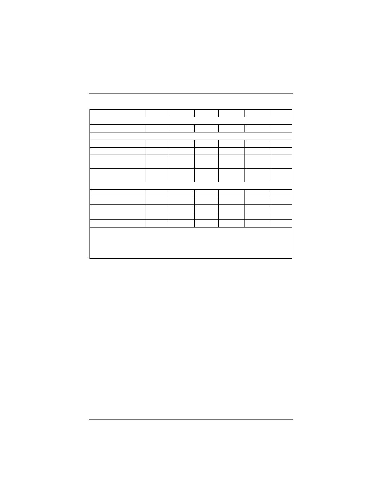
Display Capabilities
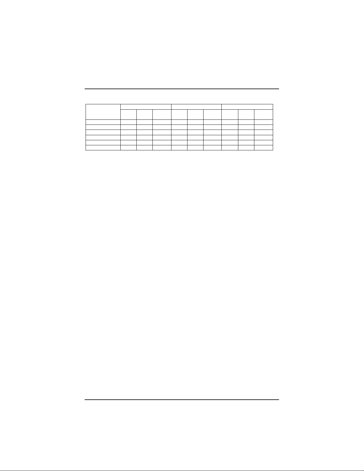
Depending on the memory configuration, the ATI RAGE IIC/PRO can give a
maximum resolution of 1600x1200 at 65K colors and a refresh rate of 76Hz. The
following table shows resolution/color as a function of memory size and refresh rate.
It also gives a breakdown of the use of memory in various 3D applications.
12
Page 28
Chapter 1 - Getting Started
DISPLAY 256 COLORS HIGH COLOR TRUE COLOR
SCREEN 2MB 4MB 6MB/ 2MB 4MB 6MB/ 2MB 4MB 6MB/
RESOLUTION — — 8MB — — 8MB — — 8MB
640 x 480 200 200 200 200 200 200 200 200 200
800 x 600 200 200 200 200 200 200 200 200 200
1024 x 768 150 150 150 150 150 150 — — —
1152 x 864 120 120 120 120 120 120 — — —
1280 x 1024 100 100 100 — 100 100 — — —
1600 x 1200 85 85 85 — 85 85 — — —
Audio
The onboard CrystalClear™ CS4235 chip includes an integrated FM synthesizer and
a Plug-and-Play interface. In addition, it includes hardware master volume control as
well as extensive power management and 3D sound technology. It is compatible with
the Microsoft® Windows Sound System™ standard and will run software written to
the Sound Blaster™ and Sound Blaster Pro™ interfaces. It is fully compliant with
Microsoft’s PC97 and PC98 audio requirements.
Features
n Compatible with Sound Blaster™, Sound Blaster Pro™, and Windows
Sound System™
n Advanced MPC3-compliant input and output mixer
n Enhanced stereo full duplex operation
n Dual type-F DMA support
n Integrated CrystalClear™ 3D stereo enhancement
n Internal default PNP resources
13
Page 29

SAHARA System User Guide
Ethernet PCI Bus (LAN)
The onboard Intel 82558 chip is a fully integrated 10BASE-T/100BASE-TX LAN
controller. It consists of both the MAC controller and the 10/100 Mbps physical layer
interface. Its true 32-bit architecture enables it to perform high speed data transfers
on the PCI bus using four DMA channels. Its sophisticated microcode-based engine
enables the 82558 chip to process high level commands and perform multiple
operations without CPU intervention. Its 3 Kbyte Transmit and Receive FIFOs
provide large on-chip storage space for both transmitted and received frames. The
82558 chip provides full support for both half duplex and full duplex operation, as
well as support for full duplex flow control.
Features
n Internal transmit and receive FIFOs (3 Kbytes each)
n FLASH support up to 64 Kbytes
n EEPROM support
n ACPI and PCI Power Management standards compliant
n Remote Wake Up (Magic Packet) support
n Full or half duplex capable at 10 or 100 Mbps
14
Page 30

Introduction
This chapter provides you with the necessary information and instructions you
need to set up the new SAHARA System. This chapter also guides you through
starting up the computer for the first time and doing basic operations. Setting
up the computer involves the following steps:
n Connecting a display monitor to the computer
n Connecting a keyboard to the computer
n Connecting a PS/2 mouse to the computer
n Connecting any other peripherals that you may have including a printer, a
serial mouse, audio equipment or a USB peripheral
n Plugging in and turning on the computer
Chapter 2
GETTING READY TO GO
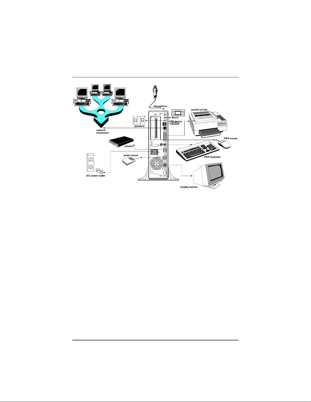
System Connections
The SAHARA System should look like the following figure after all the initial
connections are in place.
15
Page 31
SAHARA System User Guide
Operating System
A computer starts up only when there is an operating system (O/S) existing on
its hard disk or when a system diskette is in its primary drive, normally designated as drive A. Think of the operating system or user interface as the translator between the computer chip and you. The computer chip sits there with its
tremendous computing power, but it needs a way to tell you what is going on
and you need a way to tell it what you want it to do. You communicate through
the user interface.
Most computers are sold with an operating system pre-installed. If this is true
of your computer, you can be sure that the hard disk is pre-formatted and
contains the files necessary for booting.
If the hard disk is not yet formatted and the O/S not yet installed into it, read
carefully the related manuals for instructions in the proper hard disk formatting
and running of the Setup program of MS-DOS.
The computer automatically loads the O/S after you turn it on. This process is
called booting.
If you are booting from a system diskette, see the section on Diskette Operations to know how to insert diskettes into the drive.
If you are booting from the hard disk, proceed with the following instructions.
16
Page 32

Getting Ready to Go
Diskless LAN Station Setup
After completing the system connections described in the Section System
Connections on page 15. You can link with your local area network by simply
following the steps listed in Appendix C.
Power-On Operations
1. Turn on the computer by pressing the power button.
Each time the system power is turned on, the system runs a series of tests,
commonly referred to as POST (Power-On-Self-Test) which checks the status
of major computer devices that include the mainboard, memory, video, keyboard, and disk drive. Some status messages of POST appear on the screen.
POST compares the current hardware setup status with the default configuration information pre-entered into the system BIOS Setup. (See Chapter 4 for
details on the BIOS Setup settings.)
2. When POST detects a mismatch between the actual hardware configuration
and the BIOS Setup default settings, error messages indicating invalid
configuration appears on the screen. Normally, the message specifies the cause
of the problem, thereby giving you a hint on how to fix the problem.
When you see such an error message, refer to Chapter 5 on Troubleshooting
Tips in this manual to know how to solve the problem. If the error message
persists or if the problem is not discussed in the Troubleshooting Tips chapter,
consult your dealer or a qualified service technician for assistance.
3. When no mismatch is found and POST successfully completes its check, the
computer first tries to boot from drive A. If there is no diskette in drive A, the
computer boots from the hard disk, usually designated as drive C.
When the computer boots from the hard disk that has an operating system
properly installed on it, the system prompt, usually the C:> prompt appears.
The appearance of the C:> prompt signifies successful booting or start-up of
the system. You could now start installing or using the application programs
like MS-Windows.
17
Page 33

SAHARA System User Guide
Diskette Operations
Inserting/Removing Diskettes
Floppy disks are the portable storage system for your computer, similar to file
folders for your work. On floppy disks you can store the projects created in
the computer, make an extra copy or carry them to another computer.
When you are starting up the system for the very first time, the disk drives
probably will have the cardboard head protector inserted into the drive.
1. Remove the cardboard head protector from the disk drive. Press the ||||||||||||| |
eject button to pull out the cardboard. Keep the cardboard for future ||||||||||||||
use in case you may have to move the system.
2. If the system does not have a hard disk and an operating system, insert a
system diskette (that comes with the operating system diskettes and contains
the COMMAND.COM file).
When you insert a diskette in the floppy disk drive (FDD), insert the diskette
with the label side up and the metal plate first into the drive until the diskette
locks in place.
3. To remove a diskette from the FDD, press the diskette eject button to make the
diskette come out partway out of the drive and gently pull out the diskette by
hand.
18
When the system is accessing the drive (indicated by the lit in-use
indicator), be careful not to remove a diskette or accidentally press
the power button. Doing so may destroy the data on the diskette
and may damage the drive mechanism.
Even though the 3.5-inch floppy diskette are encased in a hard
plastic coating, they should be treated with care.
Page 34
Getting Ready to Go
Diskette Types
The type of diskette that you can use in a disk drive depends on the drive size.
See the following table to know the drive/diskette compatibility features:
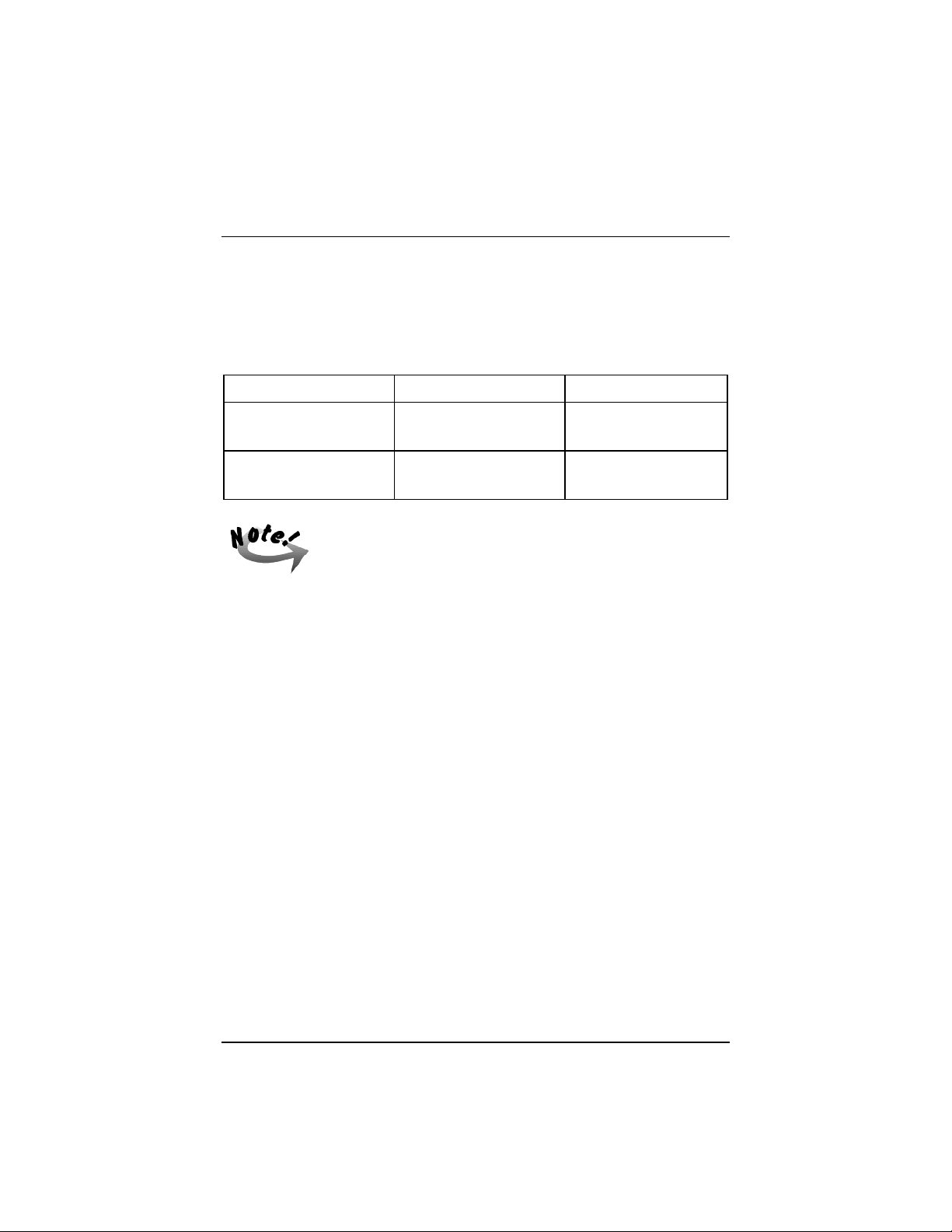
DRIVE CAPACITY DISKETTE DENSITY READ/WRITE
High Capacity
1.44MB 3.5 inch
Standard Capacity
720KB 3.5 inch
* To format a standard-density diskette in a high-capacity drive,
you must include certain parameters in the formatting command.
Refer to the operating system documentation for details.
Note that the capacity of a standard-density diskette will not
change when it is formatted in a high-capacity drive.
A standard-capacity disk drive might not be able to read a
standard-capacity diskette that was written or formatted in a highdensity drive.
High Density Yes/Yes
Yes/Yes*
High Density
Standard Density
Yes/Yes
No/No
Backing Up Master Diskettes
Master diskettes are the original diskettes of the operating system or software
programs. As a safeguard against unexpected damage or alterations, make back
up copies of the master diskettes and use the backup diskettes for everyday operation. Store the master diskettes in a safe place. Consult the MS-DOS or MSWindows documentation to know how to properly back up diskettes.
The hard disk has a much larger capacity and faster access speed than the
floppy disk drive. For your convenience, you are advised to copy frequentlyused program files from your MS-DOS or utility diskettes or other application
programs into your hard disk so you can run the programs from there.
One of the most important uses of floppy disks is to back up your work so that
if anything happens to the copy that is on the hard drive (hard drives can crash
and erase all your work) you have a copy. Get in the habit of making backup
copies of your work often. Store a copy at another location for extra protection.
As folks in the computer world always say, “It isn’t a question of if your hard
drive will crash, only a question of when.”
19
Page 35

SAHARA System User Guide
Resetting the Computer
You may re-start the system (that is, go through booting and POST operations
again) without turning the computer power off and on again. There are two
ways to do this:
1. Press the Reset button on the front panel of the system.
2. Press <Ctrl> + <Alt> + <Del> keys simultaneously.
Power-Off Operations
If you are using a DOS-based program:
1. Save the data and exit to the system prompt.
2. Remove the diskette, if any, from the disk drive.
3. Turn off the computer by pressing the Power Button.
4. Turn off the power of any connected external devices.
If you are using any MS Windows-based program, make sure you shut it
down first before turning off system power:
1. Save and close any open files. Though most programs will remind you to save
your work if you forget, taking the initiative to save your work is a good habit
to form.
2. Click the Close button for the program window.
3. If you have no unsaved documents, the program closes and you return
immediately to the Windows desktop.
4. If you have an unsaved work or a work containing unsaved changes, the
program asks you whether to save it. Click on “Yes” to save it or on “No” to
abandon it.
5. If you click on “Yes” and the document has never been saved before, the Save
As dialog box appears. Name and save your work.
6. To turn off your computer after closing the program, it’s very important to
shut down Windows first. Click the Start button, then click on the Shut Down
option to display the Shut Down Windows dialog box.
7. Click the “Yes” button, then wait until you see the message “It’s now safe to
turn off your computer.” before you turn the computer off.
20
Page 36

Getting Ready to Go
If you have to turn the computer on again immediately after turning
it off, wait for at least five seconds. Turning the computer off and
on rapidly can damage it.
21
Page 37

SAHARA System User Guide
— This Page Intentionally Left Blank —
22
Page 38

Chapter 3
MAKING UPGRADES EASY
Before You Begin
We recommend that you contact your SAHARA System reseller for carrying out any
system upgrades. The following upgrades to the system are best if attempted only by
a qualified technician.
Make sure you have a stable and clean working environment. Dust and dirt can get
into computer components and cause malfunction. Use containers to keep small
components separated. Many of the screws on the computer are of different sizes; if
you place them together you may spend a lot of time trying to track down the correct
screw when you are assembling the computer back together. Also, placing all small
components in a safe container keeps them from getting lost. Having adequate
lighting and using proper tools can prevent you from accidentally damaging the
internal components. Most of the procedures that follow require only a few simple
tools, including the following:
• A Philips screwdriver
• A flat tipped screwdriver
• A set of jeweler’s screwdriver
• A multimeter (not always required)
• A grounding strap
23
Page 39
SAHARA System User Guide
Most of the electrical connections can be disconnected by using your fingers. It is
recommended that you do not use needle-nosed pliers to disconnect connections as
this can damage the soft metal or plastic parts of the connectors. Many connectors
have tabs to keep them secure. After the tabs are disengaged the connector should
easily slide out. You can use a small screwdriver to gently pry some of the connectors
loose. If the connector does not come out easily, make sure that nothing is
obstructing it, and gently rock it back and forth in its slot until it loosens enough to
come out. Do not force it!
Before working on internal components, make sure that the computer’s power is off.
Ground yourself before touching any internal components by touching a metal object.
Static electricity can damage many of the computer’s electronic components. Humid
environments tend to have less static electricity than dry environments. A grounding
strap is warranted whenever danger of static electricity exists.
Removing the Chassis Cover
1. Turn the power of the system unit off and all connected peripherals.
2. Disconnect all power cords and cables from the system unit.
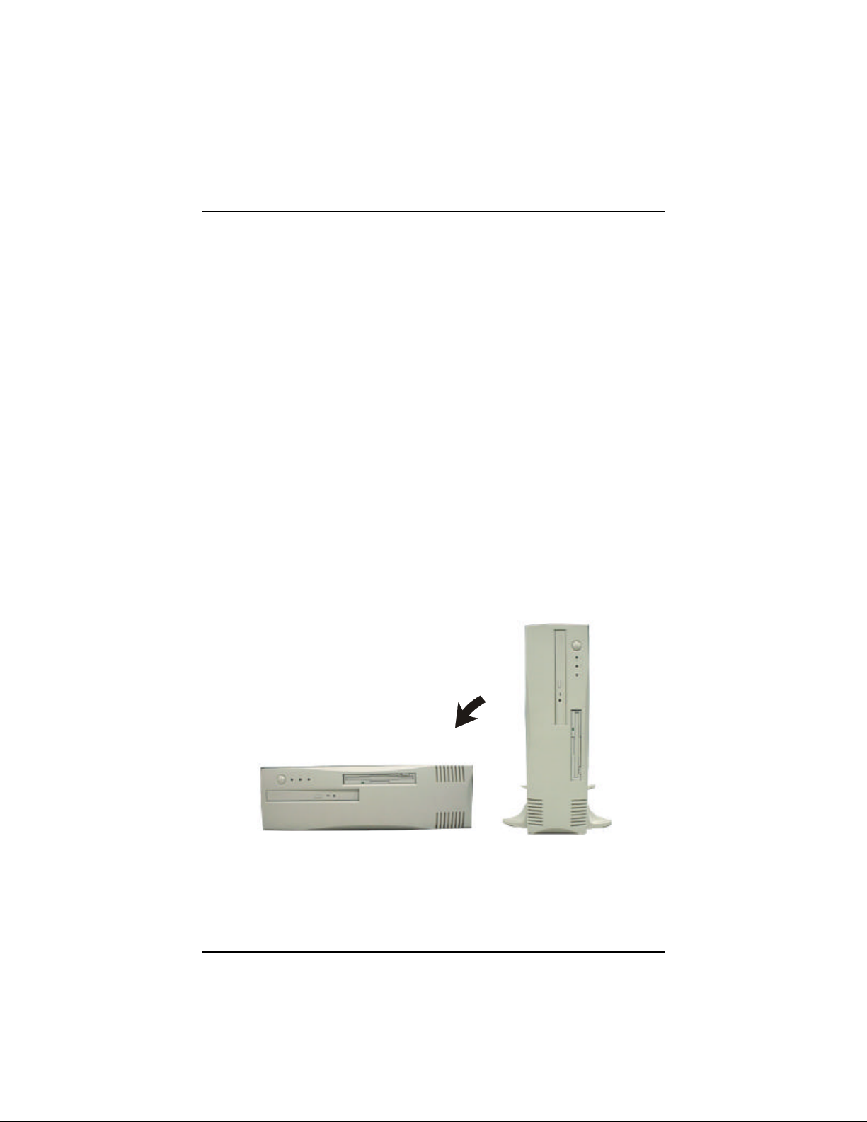
3. Remove the system unit from its base and place it on a flat and stable sur-
face.
24
Page 40
Chapter 3 - Making Upgrades Easy
4. Loosen the three screws securing the chassis cover with a Philips screw-
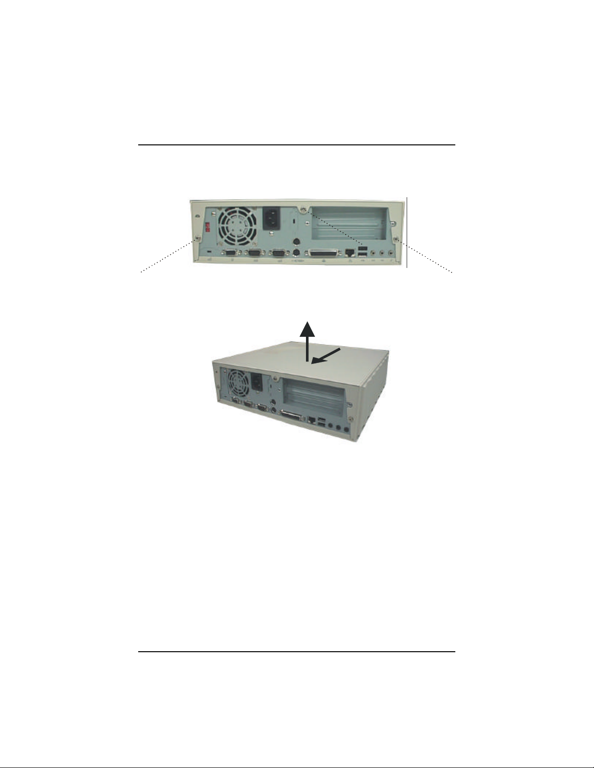
driver.
5. Grasp the cover with both hands. Slide the cover towards you and pull
upward until it slides off the chassis.
25
Page 41
SAHARA System User Guide
Removing the Front Panel Chassis
The SAHARA System’s innovative design features a slide out front panel chassis
giving direct access to the mainboard for optimized final configuration, while making
upgrades and servicing quick and easy. Utilizing the highest quality, industrystandard components, the SAHARA System eases the workload of the system
administrator while increasing up-time for the corporate user.
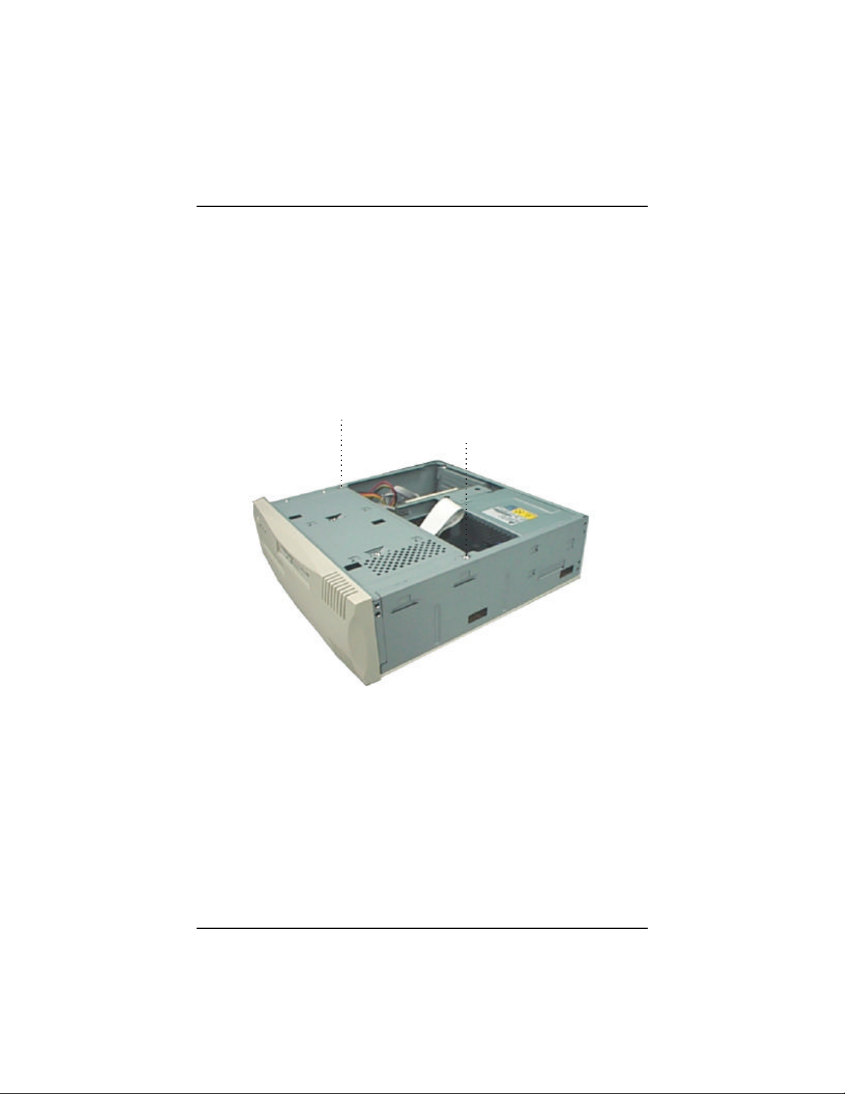
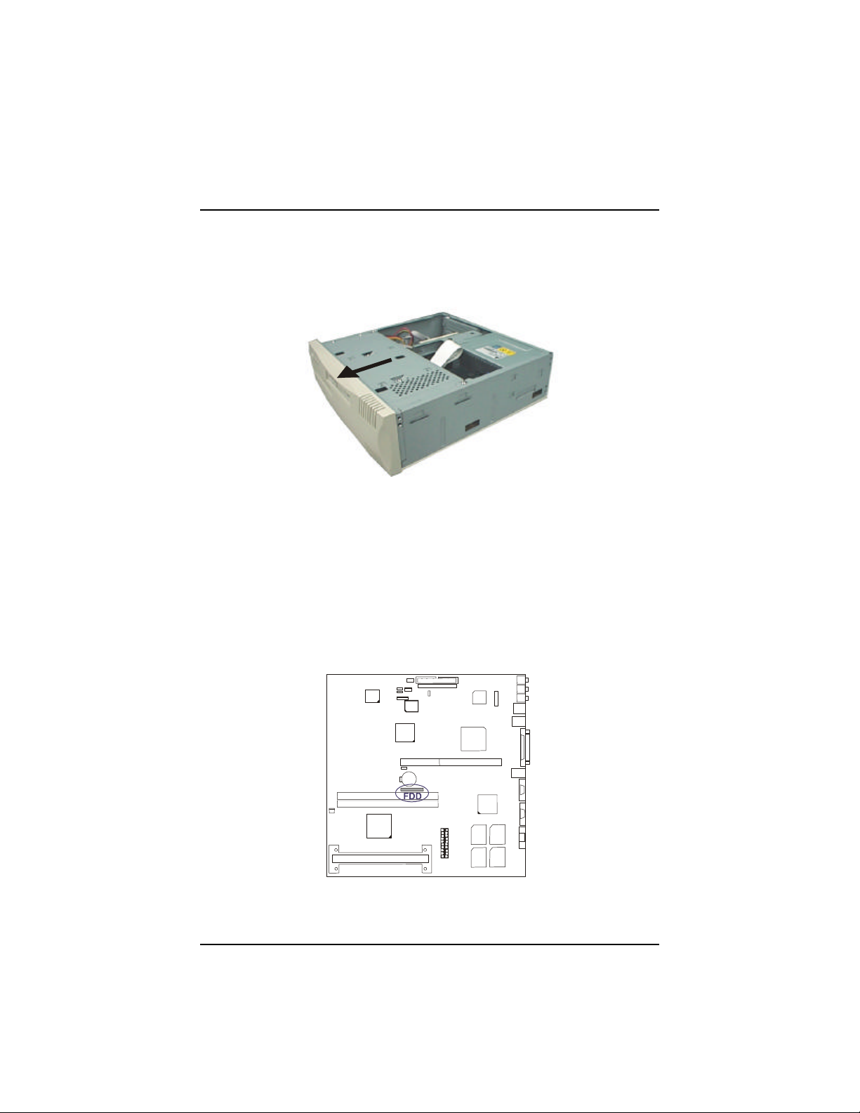
1. Using a screwdriver, remove the two screws holding the front panel
chassis.
26
Page 42
Chapter 3 - Making Upgrades Easy
2. Slide the front panel chassis away and place it slightly in front of the main
body, taking care not to damage the sensitive FFC-cable of the slim floppy
disk drive and other system and mainboard components.
Installing the Hard Disk Drive (HDD)
To install a Hard Disk Drive, please refer to the following steps:
1. Remove the front panel chassis (see previous section “Removing the
Front Panel Chassis”).
2. Disconnect the FFC-cable of the slim floppy disk drive from the main-
board by pulling up both sides of the 26 pin block connector to release it.
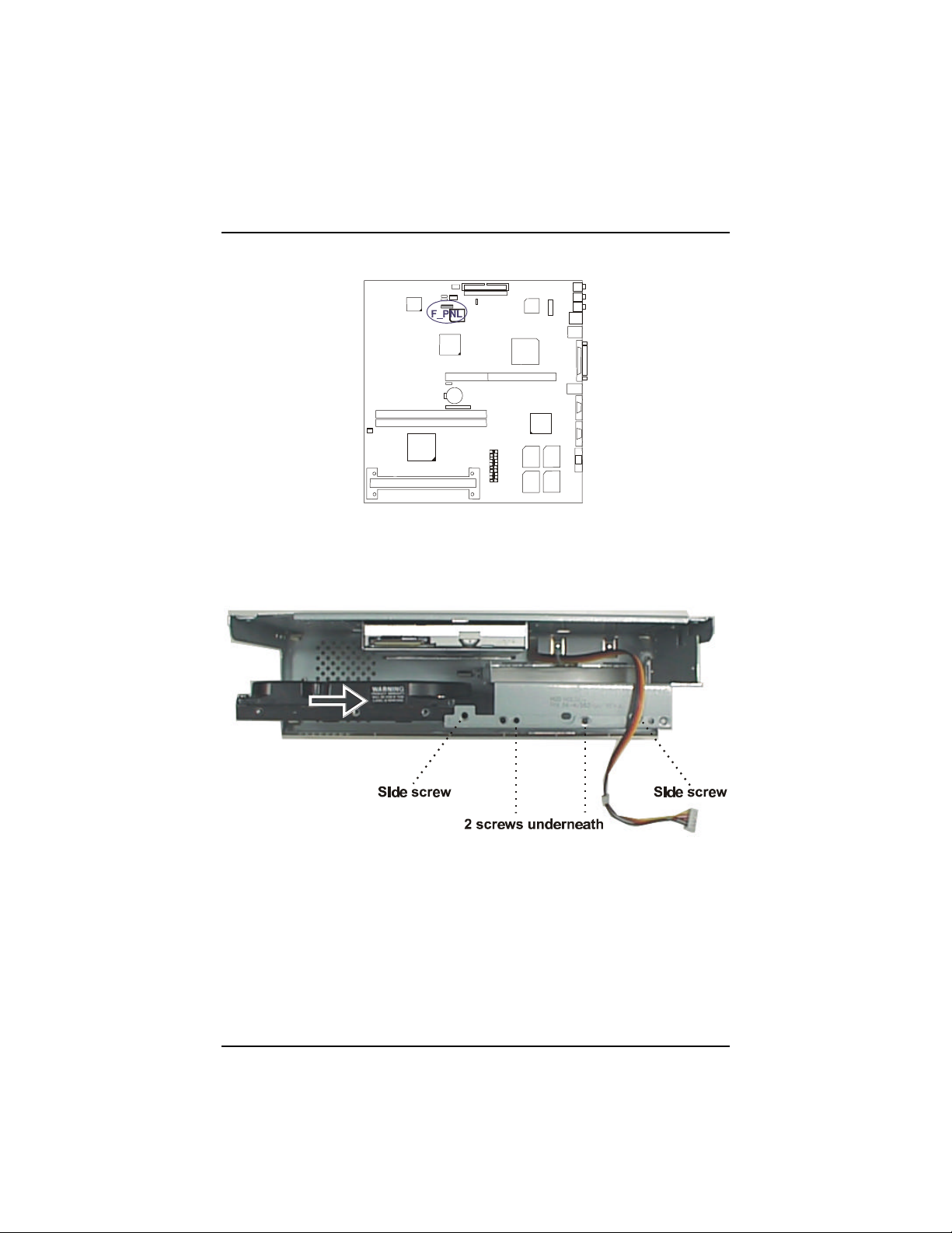
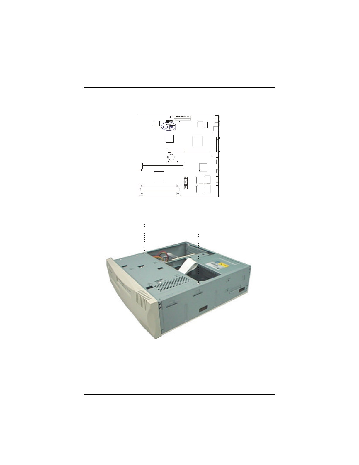
3. Pull out the LED wires plugged to the F_PNL connector.
27
Page 43
SAHARA System User Guide
4. Slide the new HDD on to the HDD holder and secure the four screws (two
screws on one side and two screws underneath) to hold the hard disk drive
in place.
28
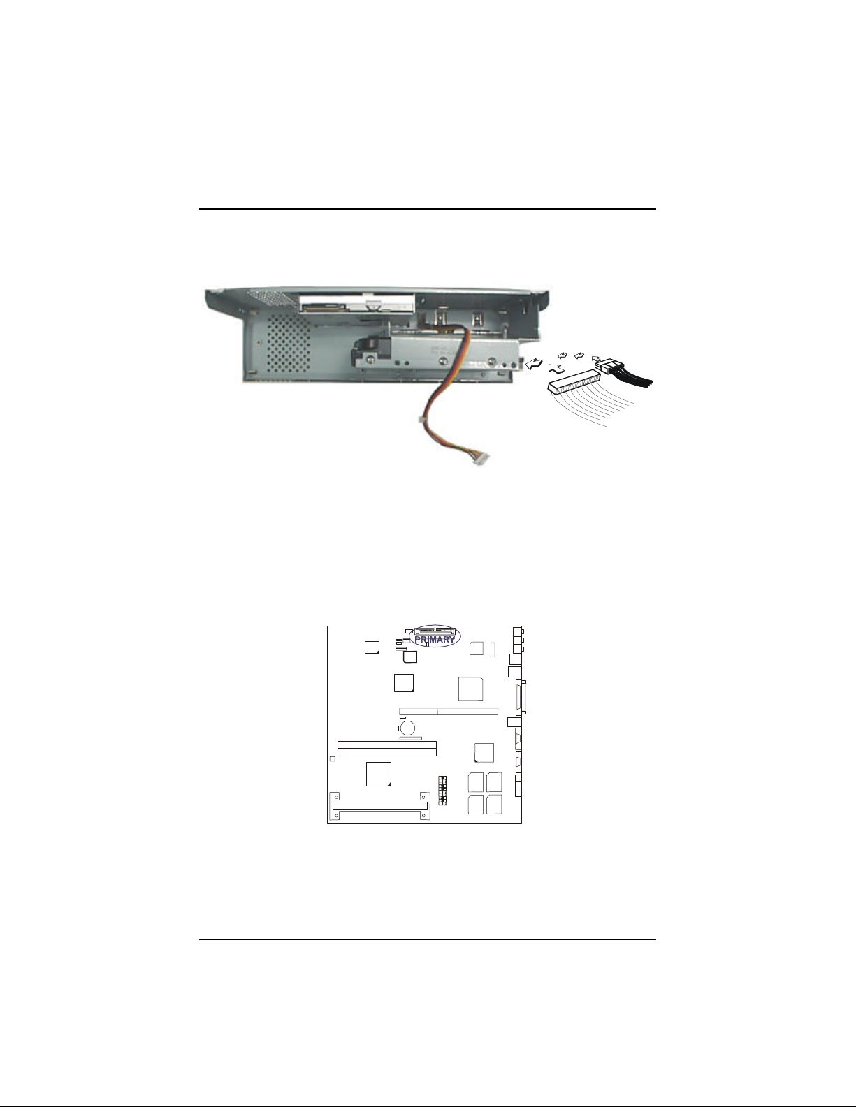
5. Connect one end of the IDE ribbon cable onto the hard disk drive, taking
care to align the ribbon cable with the red stripe on to pin-1 of the hard
disk drive connector (the side nearest the power plug connector).
Page 44
Chapter 3 - Making Upgrades Easy
6. Connect the power cord coming from the power supply to the DC power
connector located at the back of the HDD.
7. Place the front panel chassis slightly in front of the main chassis.
8. Connect the other end of the provided IDE hard disk ribbon cable onto the
PRIMARY connector on the mainboard, taking care to align the ribbon
cable with the red stripe on to pin-1 of the PRIMARY connector. Pin-20
is removed to prevent inserting in the wrong orientation when using ribbon cables with pin-20 plugged.
29
Page 45
SAHARA System User Guide
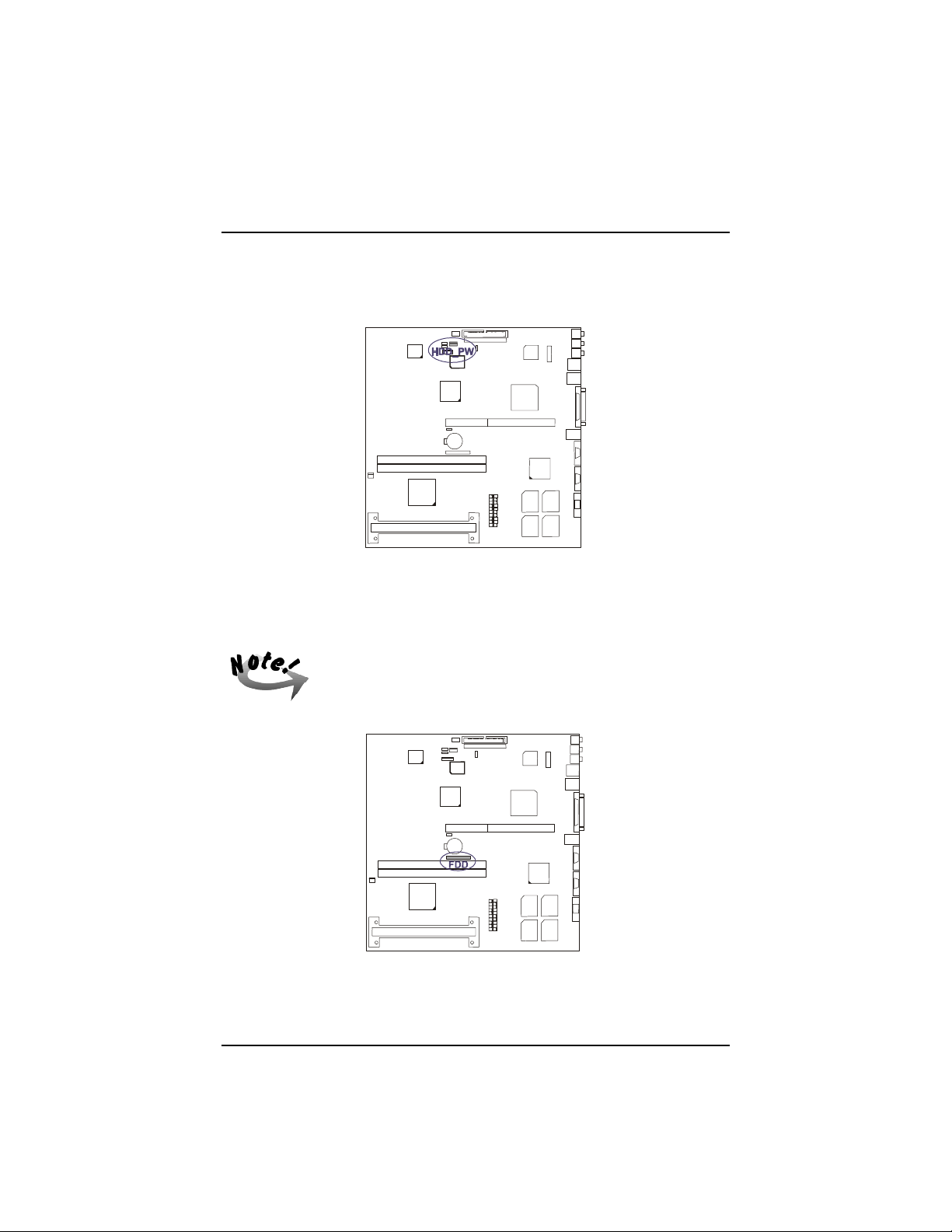
9. Connect the power cord coming from the DC power connector located at
the back of the HDD to the HDD_PW connector.
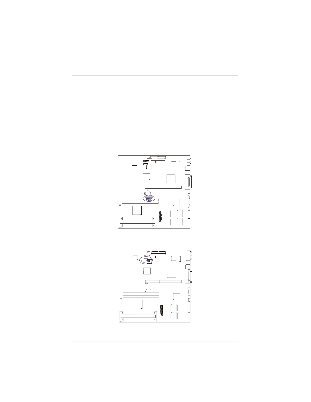
10. Connect the FFC-cable of the slim floppy disk drive to the 26-pin FDD
block connector on the mainboard by inserting the silver-finger contact
and press down the FDD connector on both sides to lock it in place.
The FFC-cable should always be inserted with the side with the
exposed silver-finger in contact with the FDD connector pins.
30
Page 46
Chapter 3 - Making Upgrades Easy
11. Plug in the LED wires to the F_PNL connector.
12. Push the front panel chassis all the way into the main chassis and secure
the two screws to fix the front panel chassis in place.
31
Page 47
SAHARA System User Guide
Installing the CD-ROM Drive
To install a CD-ROM drive, refer to the following steps:
1. Remove the front panel chassis (see previous section “Removing the
Front Panel Chassis”).
2. Disconnect the FFC-cable of the slim floppy disk drive from the main-
board by pulling up both sides of the 26 pin block connector to release it.
32
3. Pull out the LED wires plugged to the F_PNL connector.
Page 48
Chapter 3 - Making Upgrades Easy
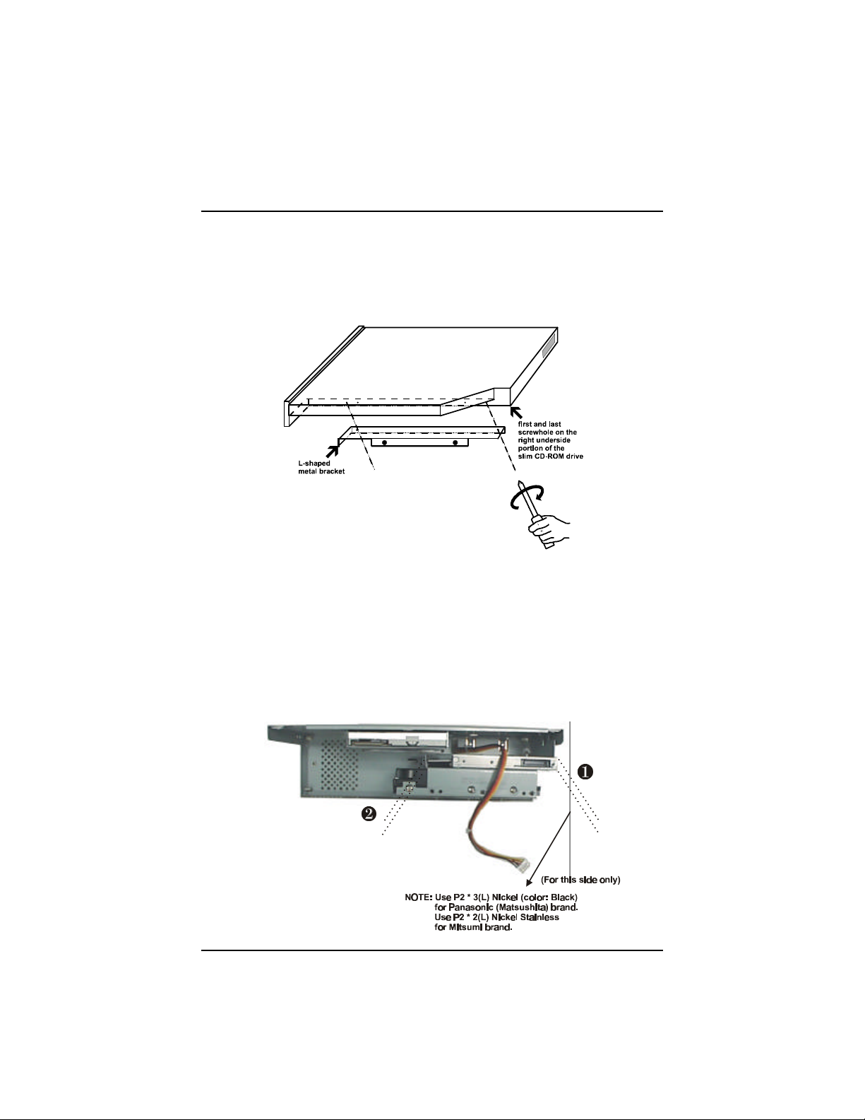
4. Attach the L-shaped metal bracket by matching the two screw holes of the
metal bracket to the first and last screw holes of the group of four screw
hole on the right underside portion of the slim CD-ROM drive and securing the two screws to it.
5. In case this is the first time that a CD-ROM drive is to be installed into the
system, remove the front panel plastic cover of the CD-ROM drive bay by
pushing outwards from the inside with your fingers.
6. Slide the new slim CD-ROM drive on to the CD-ROM drive holder, from
the inside of the front panel chassis towards the front, and secure the four
screws (two mini-screws on one side first and then the two regular-sizescrews on the other) to hold the CD-ROM drive in place.
33
Page 49
SAHARA System User Guide
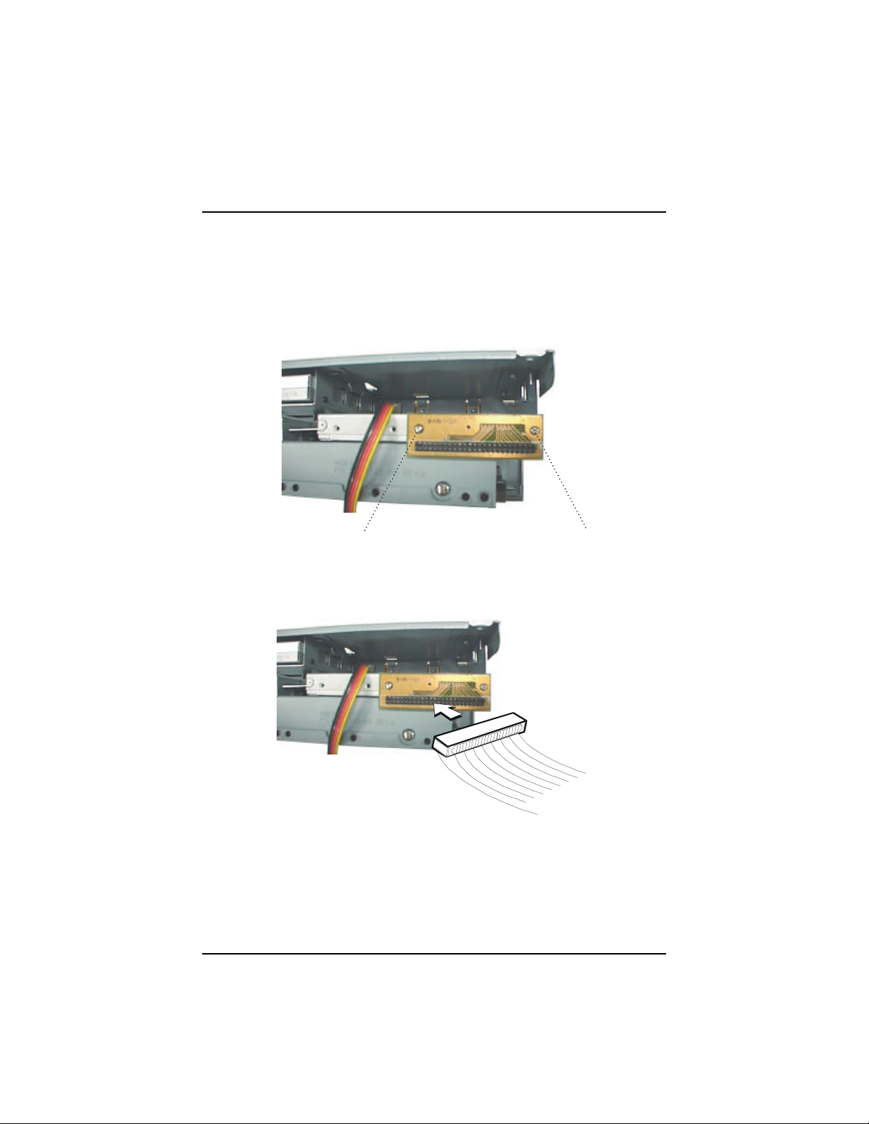
7. Attach the CD-ROM drive adaptor to the CD-ROM drive adaptor con-
nector located at the back of the slim CD-ROM drive, by (a.) first securing
the copper hexagonal bolt to the rear of the slim CD-ROM drive by hand
and, (b.) securing the two mini-screws from the CD-ROM drive adaptor
into the copper hexagonal bolt with a mini-screwdriver.
8. Connect one end of the CD-ROM drive ribbon cable onto the slim CD-
ROM drive, taking care to align the ribbon cable with the red stripe on to
pin-1 of the CD-ROM drive adaptor connector.
34
9. Place the front panel chassis slightly in front of the main chassis.
Page 50
Chapter 3 - Making Upgrades Easy
10. Connect the other end of the provided CD-ROM drive ribbon cable onto
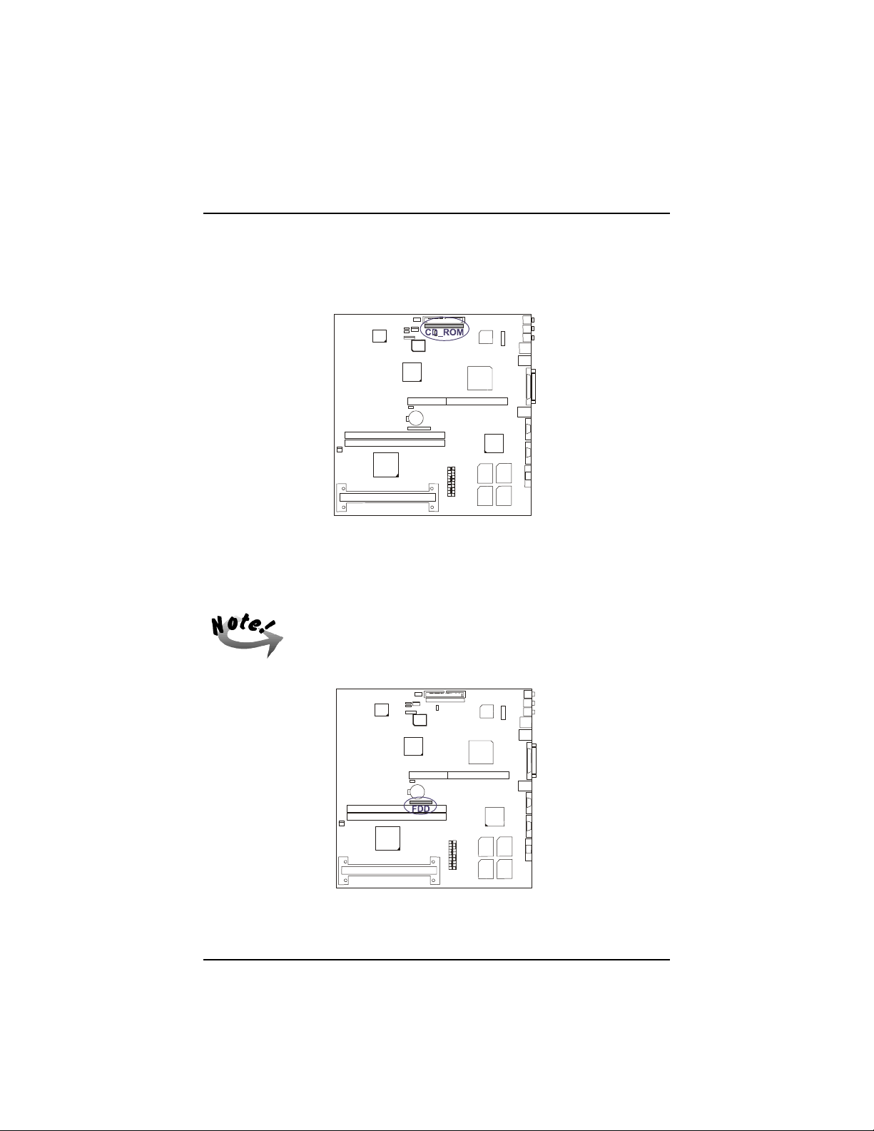
the CD_ROM connector on the mainboard, taking care to align the ribbon
cable with the red stripe on to pin-1 of the CD_ROM connector.
11. Connect the FFC-cable of the slim floppy disk drive to the 26-pin FDD
block connector on the mainboard by inserting the silver-finger contact
and press down the FDD connector on both sides to lock it in place.
The FFC-cable should always be inserted with the side with the
exposed silver-finger in contact with the FDD connector pins.
35
Page 51
SAHARA System User Guide
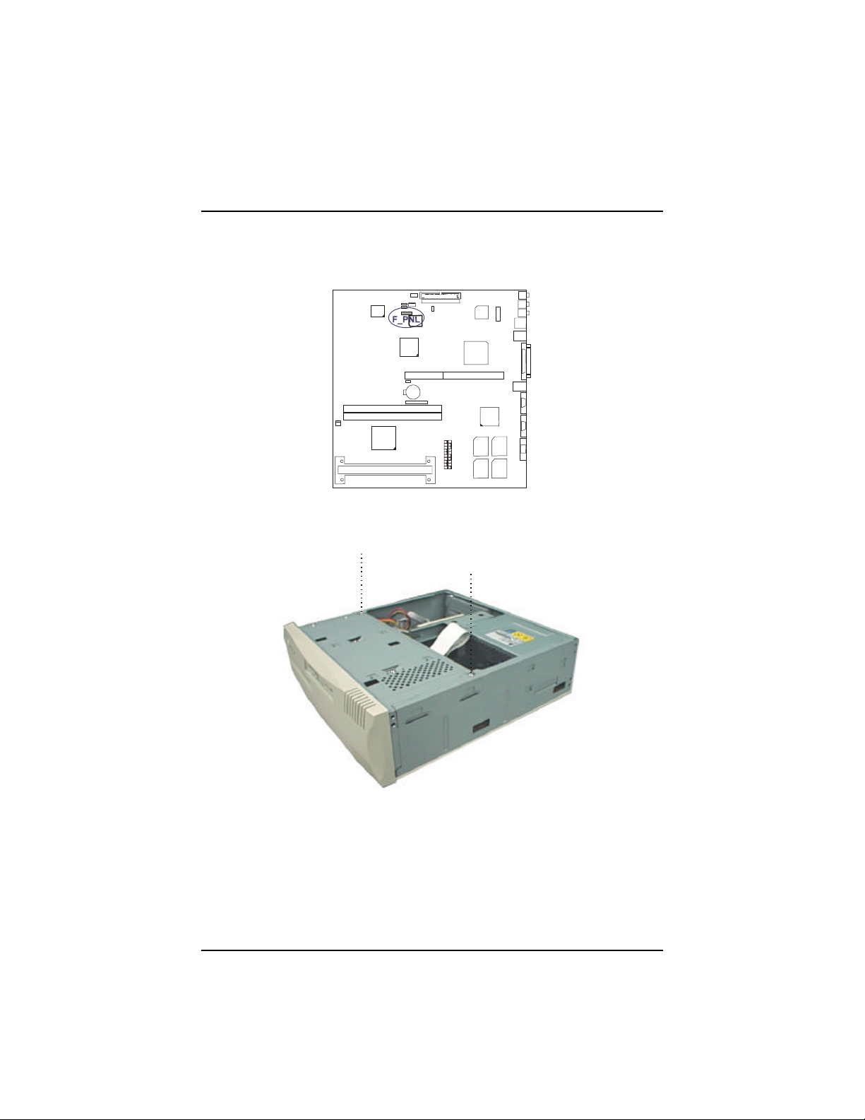
12. Plug in the LED wires to the F_PNL connector.
13. Push the front panel chassis all the way into the main chassis and secure
the two screws to fix the front panel chassis in place.
36
Page 52
Chapter 3 - Making Upgrades Easy
Re-installing the Chassis Cover
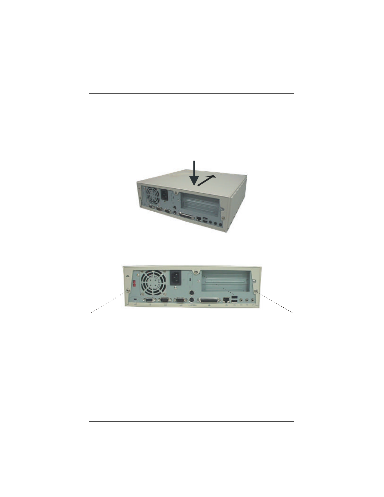
To re-install the chassis cover follow these steps:
1. Place the chassis cover onto the chassis until it is positioned in place.
2. Fasten the three screws to secure the chassis cover with a Philips screw-
driver.
37
Page 53

SAHARA System User Guide
— This Page Intentionally Left Blank —
38
Page 54

Chapter 4
BIOS SETUP
The system comes with the Award BIOS chip that contains the ROM Setup
information of the system. This chip serves as an interface between the processor and
the rest of the system's components. This chapter explains the information contained
in the Setup program and tells you how to modify the settings according to the
system configuration.
The BIOS ROM of the system stores the Setup utility. When you turn on the
computer, the system lets you run this program. This appears during the Power-OnSelf-Test (POST). Press the <Delete> key to call up the Setup utility. If you are a
little bit late pressing the mentioned key(s), POST will continue with its test routines,
thus preventing you from calling up Setup. If you still need to call Setup, reset the
system by simultaneously pressing the <Ctrl>, <Alt> and <Delete> keys, or by
pushing the Reset button on the system case.
39
Page 55
SAHARA System User Guide
Main CMOS Setup
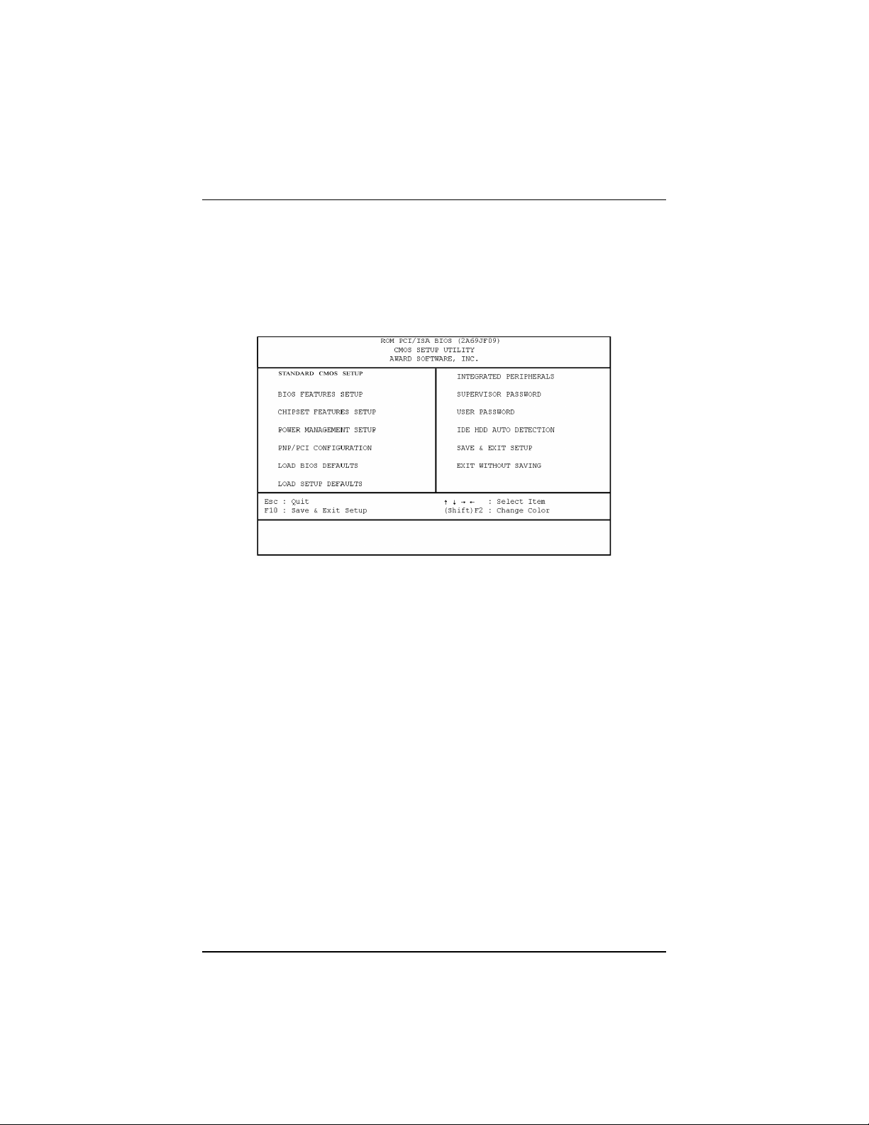
When you run Setup, the CMOS SETUP UTILITY main program screen will appear
with the following options:
A section at the bottom of the above screen displays the control keys for this screen.
Take note of these keys and their respective uses. Another section just below the
control keys section displays information on the currently highlighted item in the list.
Load Defaults
The “Load BIOS Defaults” option loads the minimized settings for troubleshooting.
“Load Setup Defaults” on the other hand, is for loading optimized defaults for regular
use. Choosing defaults at this level will modify all applicable settings.
40
Page 56
BIOS Setup
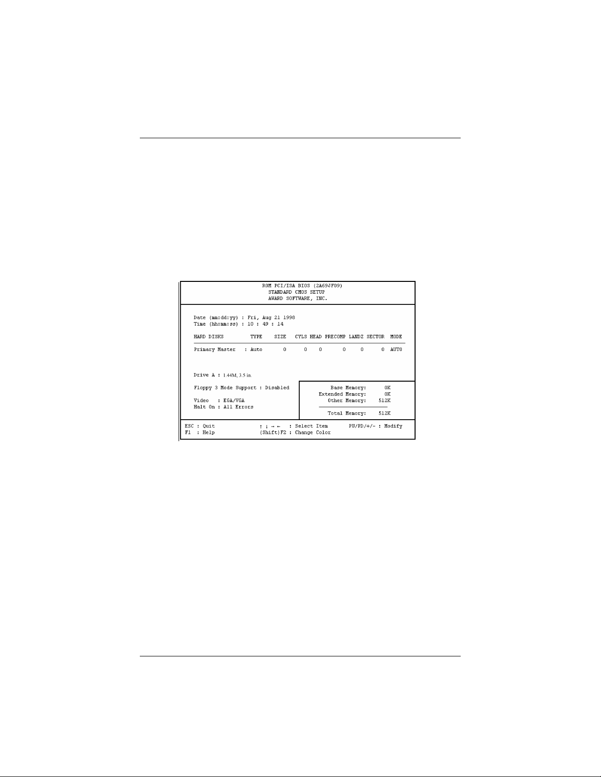
Standard CMOS Setup
The “Standard CMOS Setup” option allows you to record some basic system
hardware configuration and set the system clock and error handling. If the mainboard
is already installed in a working system, you will not need to select this option
anymore. However, if the configuration stored in the CMOS memory on the
mainboard gets lost or damaged, or if you change the system hardware configuration,
you will need to re-specify the configuration values. The configuration values usually
get lost or corrupted when the power of the onboard CMOS battery weakens.
The above screen provides you with a list of options. At the bottom are the control
keys for this screen. Take note of these keys and their respective uses. Userconfigurable fields appear in a different color. If you need information on the
selected field, press the <F1> key. The help menu will then appear to provide you
with the information you need. The memory display at the lower right-hand side of
the screen is read-only and automatically adjusts accordingly.
Date
To set the date, highlight the “Date” field and then press the page up/page down or
+/– keys to set the current date. Follow the month, day and year format. Valid values
for month, day and year are: Month: (1 to 12), Day: (1 to 31), Year: (up to 2079).
Time
To set the time, highlight the “Time” field and then press the page up/page down or
+/– keys to set the current time. Follow the hour, minute and second format. Valid
values for hour, minute and second are: Hour: (00 to 23), Minute: (00 to 59), Second:
(00 to 59) time, just press the <Enter> key twice if you do not want to modify the
current time.
41
Page 57

SAHARA System User Guide
To bypass the date and time prompts, create an AUTOEXEC.BAT
file. For information on how to create this file, refer to the MSDOS manual.
Hard Disk Drive
This field records the specifications for all non-SCSI hard drives installed in the
system. The onboard PCI IDE connectors only provides a Primary channel for
connecting to one IDE hard disk.
For IDE hard disk drive setup, you can:
n Use the Auto setting for detection during bootup.
n Use the IDE HDD AUTO DETECTION in the main menu to automatically enter
the drive specifications.
n Enter the specifications yourself manually by using the “User” option.
The entries for specifying the hard disk type include CYLS (number of cylinders),
HEAD (number of read/write heads), PRECOMP (write precompensation), LANDZ
(landing zone), SECTOR (number of sectors) and MODE. The SIZE field
automatically adjusts according to the configuration you specify. The documentation
that comes with the hard disk should provide you with the information regarding the
drive specififcations.
The MODE entry is for IDE hard disks only, and can be ignored for MFM and ESDI
drives. This entry provides four options: Normal, Large, LBA, or Auto. Set MODE to
Normal for IDE hard disk drives smaller than 528MB; set it to LBA for drives over
528MB that support Logical Block Addressing (LBA) to allow larger IDE hard disks;
set it to Large for drives over 528MB that do not support LBA. Large type of drive
can only be used with MS-DOS and is very uncommon. Most IDE drives over
528MB support the LBA mode.
Auto Detection of Hard Disks on Bootup
For the Primary Master field, you can select Auto under the TYPE and MODE fields.
This will enable auto detection of your IDE drive during Bootup. This will allow you
to change the hard drive (with the power off) and then power on without having to
reconfigure the hard drive type. If you use an older hard drive which do not support
this feature, then you must configure the hard drive in the standard method as
described above by the “User” option.
42
Page 58

BIOS Setup
After the IDE hard disk information has been entered into BIOS,
new IDE hard disks must be partitioned (such as with FDISK) and
then formatted before data can be read from and written on.
Primary IDE hard drives must have its partition set to active (also
possible with FDISK).
Drive A
This field records the type of floppy drive installed in the system. The available
options for drive A are: 1.44MB, 3.5 in. (default for Drive A); 360KB, 5.25 in.;
1.2MB, 5.25 in.; 720KB, 3.5 in.; None; 2.88MB, 3.5 in. To enter the configuration
value for a particular drive, highlight its corresponding field and then select the drive
type using the left- or right-arrow key.
Floppy 3 Mode Support
This is the Japanese standard floppy drive. The standard stores 1.2MB in a 3.5inch
diskette. This is normally disabled but you may choose from either: Disabled
(default); Drive A.
Video
Stay with the default value of EGA/VGA. The options are: EGA/VGA (default); Mono
(for Hercules or MDA); CGA 40; and CGA 80.
Halt On
This field determines which types of errors will cause the system to halt. Choose
from All Errors (default); No Errors; All, But Keyboard; All, But Diskette; and All,
But Disk/Key.
43
Page 59
SAHARA System User Guide
BIOS Features Setup
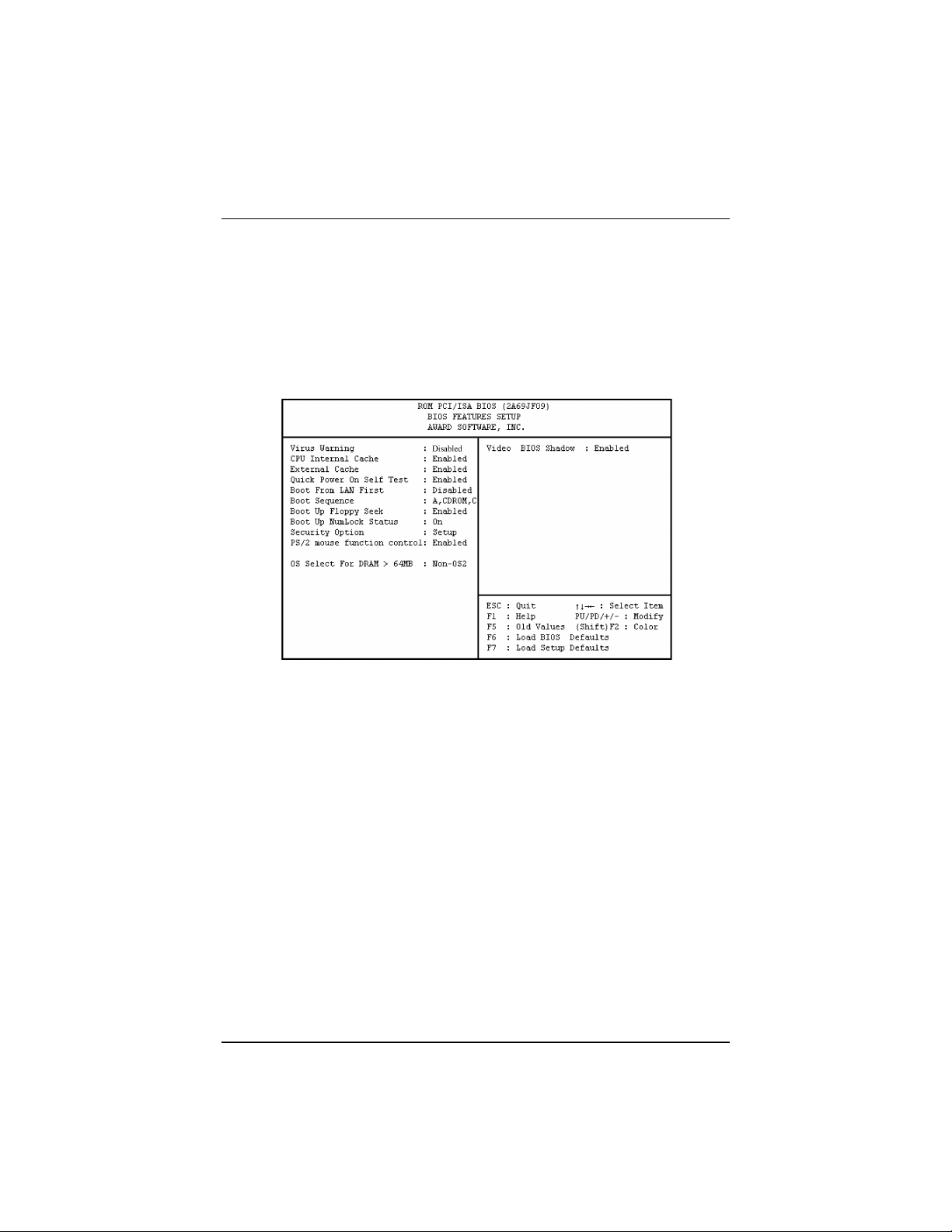
The “BIOS Features Setup” option consists of configuration entries that allow you to
improve the system performance, or lets you set up some system features according to
your preference. Some entries here are required by the mainboard’s design to remain
in their default settings.
A section at the lower right of the screen displays the control keys you can use. Take
note of these keys and their respective uses. If you need information on a particular
entry, highlight it and press the <F1> key. A pop-up help menu will appear to
provide you with the information you need. <F5> loads the last set values, <F6> and
<F7> loads the BIOS default values and Setup default values, respectively.
Virus Warning
This field protects the boot sector and partition table of the hard disk against
accidental modifications. Any attempt to write to them will cause the system to halt
and display a warning message. If this occurs, you can either allow the operation to
continue or use a bootable virus-free floppy disk to reboot and investigate the system.
This setting is recommended because of conflicts with new operating systems.
Installation of new operating systems require that you disable this to prevent write
errors. The options are: Disabled (default); Enabled.
CPU Internal Cache
When enabled, improves system performance. Disable this item when testing or
troubleshooting. The options are: Enabled (default); Disabled.
External Cache
44
Page 60

BIOS Setup
When enabled, supports an optional cache SRAM. The options are: Enabled
(default); Disabled.
Quick Power On Self Test
When enabled, allows the BIOS to bypass the extensive memory test. The options
are: Enabled (default); Disabled.
Boot From LAN First
This field allows the system to first look for an operating system at the LAN (Local
Area Network) if you have a pre-boot LAN card installed in your system that is
connected to a network server which supports this function. The options are: Enabled
(default); Disabled.
Boot Sequence
Allows the system BIOS to first try to boot the operating system from the selected
disk drive. The options are: A, CDROM, C (default); CDROM, C, A; C only; A C; C,
A.
Boot Up Floppy Seek
When enabled, assigns the BIOS to perform floppy diskette drive tests by issuing the
time-consuming seek commands. The options are: Enabled (default); Disabled.
Boot Up Numlock Status
When set to On, allows the BIOS to automatically enable the NumLock Function
when the system boots up. The options are: On (default); Off.
Security Option
Allows you to set the security level of the system. The options are: Setup (default);
System.
PS/2 Mouse Function Control
This item allows the PS/2 mouse to have exclusive use of IRQ12. The options are:
Enabled (default); Disabled.
OS Select For DRAM > 64MB
If the operating system (OS) you are using is OS2, select the option OS2; otherwise,
stay with the default setting of Non-OS2. The options are: Non-OS2 (default); OS2.
Video BIOS Shadow
When Enabled, it allows the BIOS to copy the video ROM code of the add-on video
card to the system memory for faster access. The options are: Enabled (default),
Disabled.
45
Page 61
SAHARA System User Guide
Chipset Features Setup
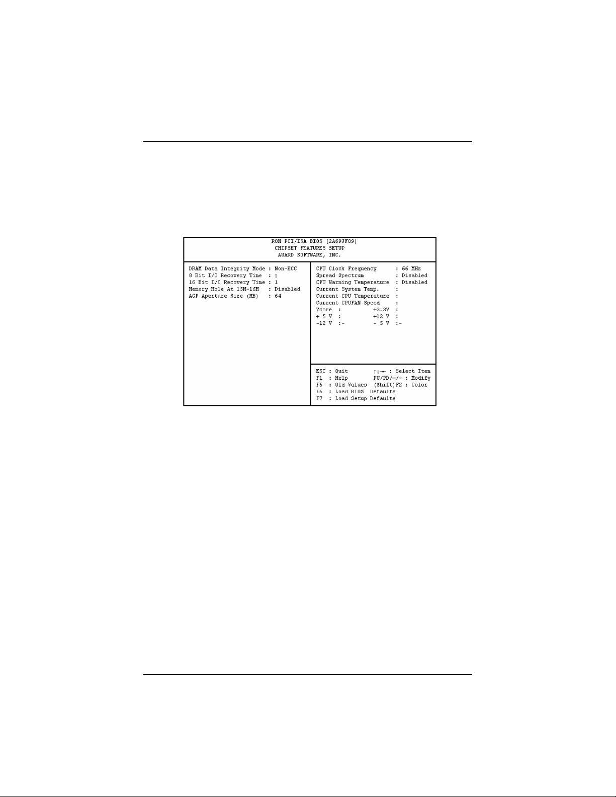
The “Chipset Features Setup” option controls the configuration of the system’s
chipset. Control keys for this screen are the same as for the previous screen.
DRAM Data Integrity Mode (available only if the mainboard uses the Intel
440LX AGPset)
This item provides software configurability for selecting between ECC (ECC
generation and checking/correction) mode or non-ECC mode of operation of the
DRAM interface. The options are: Non-ECC (default); ECC (set only if the onboard
chip is the Intel® 82443LX and installed DIMM is with parity check).
8 Bit I/O Recovery Time
This item sets the timing for 8-bit ISA cards. The options are: 1 (default); 2 to 8; NA.
16 Bit I/O Recovery Time
This item sets the timing for 16-bit ISA cards. The options are: 2 (default); 1 to 4;
NA.
Memory Hole At 15M-16M
When Enabled, the memory hole at the 15MB address will be relocated to the
15~16MB address range of the ISA cycle when the processor accesses the 15~16MB
address area. When Disabled, the memory hole at the 15MB address will be treated
as a DRAM cycle when the processor accesses the 15~16MB address. The options
are: Disabled (default), Enabled.
AGP Aperture Size (MB)
46
Page 62
BIOS Setup
This item allows you to select the main memory frame size for use by the onboard
RAGE IIC AGP chip. The options are: 64 (default); 128; 256; 4; 8; 16; 32.
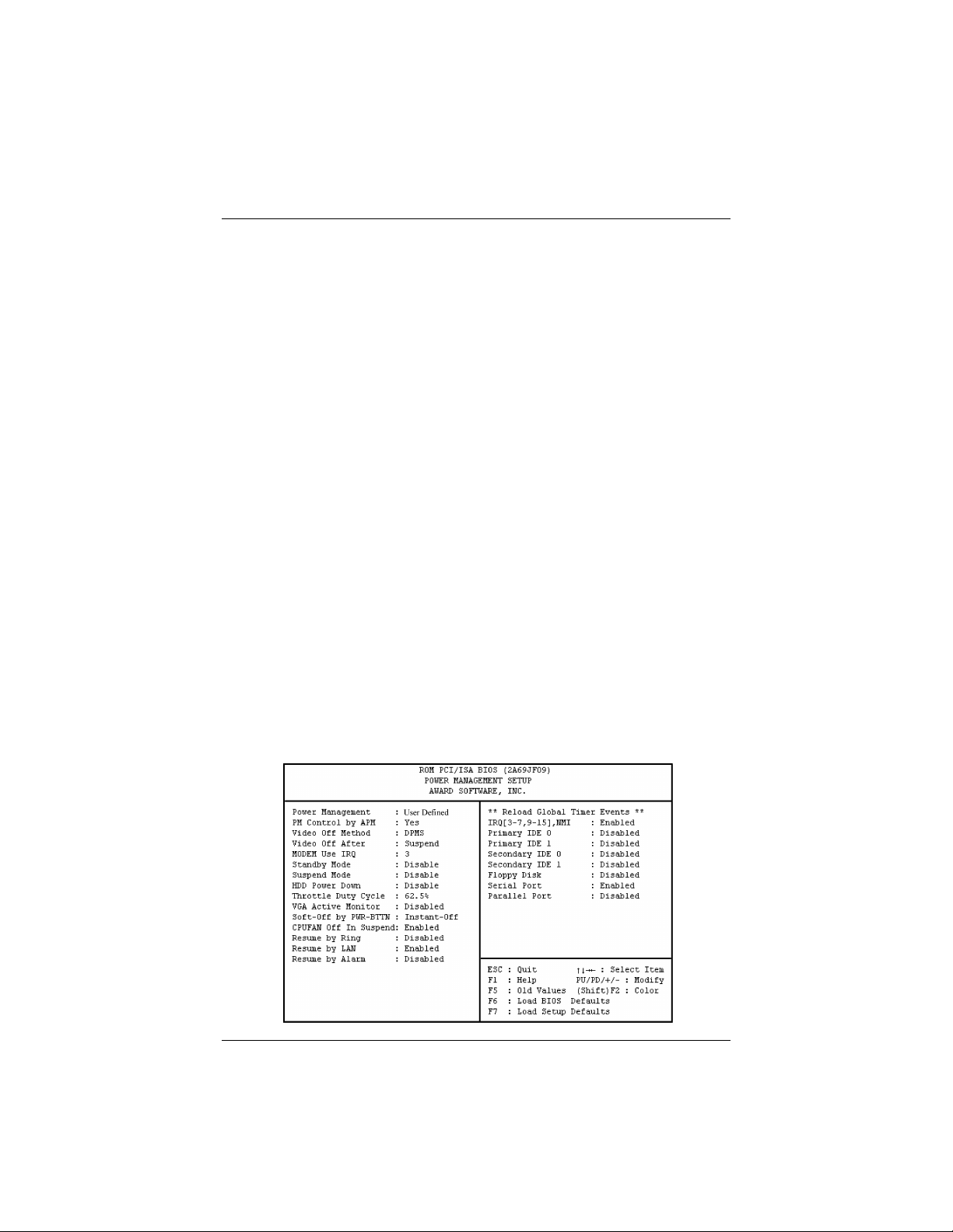
CPU Clock Frequency
This item allows you to set the ratio of the CPU external clock to the PCI bus clock.
The options are: 66 MHz (default); 50 MHz; 68 MHz; 60 MHz, 75MHz.
Spread Spectrum
This item allows you to take advantage of the center spread-type or down spread-type
of spread spectrum. The options are: Disabled (default), Enabled.
CPU Warning Temperature
This item allows you to set the maximum allowable CPU temperature for system to
perform normally. When CPU temperature exceeds this temperature, system will
proceed to enter Standby Mode of operation causing system to slowdown. The
options are Disabled (default); 500C/1220F; 530C/1270F; 560C/1330F; 600C/1400F;
630C/1450F; 660C/1510F; 700C/1580F.
Current System Temp / Current CPU Temperature / Current CPU Fan
Speed / VCORE / +3.3(V) / +5.0(V) / +12(V) / –12(V) / –5.0(V)
These items allow end users and technicians to monitor data provided by the BIOS
on this mainboard. It is not user-configurable.
Power Management Setup
The “Power Management Setup” option allows you to reduce the power consumption
of the system. This feature turns off the video display and shuts down the hard drive
after a period of inactivity.
47
Page 63

SAHARA System User Guide
Power Management
This field acts as the master control for the power management modes. Max Saving
puts the system into power saving mode after a brief period of system inactivity; Min
Saving is almost the same as Max Saving except that this time the system inactivity
period is longer; Disabled disables the power saving features; User Defined allows
you to set power saving options according to your preference. The options are: User
Defined (default); Min Saving; Max Saving.
PM Control by APM
The option No allows the BIOS to ignore the APM (Advanced Power Management)
specification. Selecting Yes will allow the BIOS to wait for APM's prompt before it
enters Standby mode or Suspend mode. If the APM is installed, it will prompt the
BIOS to set the system into the power saving mode after all tasks are done. The
options are: Yes (default); No.
Video Off Method
The option V/H SYNC+Blank allows the BIOS to blank off screen display by turning
off the V-Sync and H-Sync signals sent from the add-on VGA card. DPMS allows
the BIOS to blank off screen display via the add-on VGA card which supports DPMS
(Display Power Management Signaling function). Blank Screen allows the BIOS to
blank screen display by turning off the red-green-blue signals. The options are:
DPMS (default); Blank Screen, V/H SYNC+Blank.
Video Off After
This item allows you to activate the video off feature for the display monitor power
management. The options are: Suspend (default); Standby; NA.
48
Page 64

BIOS Setup
MODEM Use IRQ
This feature allows you to select the IRQ# to meet the modem's IRQ#. The options
are: 3 (default); NA; 4; 5; 7; 9; 10; 11.
Standby Mode/Suspend Mode
Sets the period of time after which Standby/Suspend Mode activates. At Max Saving,
Standby/Suspend Mode will activate after 1 minute. At Min Saving,
Standby/Suspend Mode will activate after 1 hour. If Power Management option is set
at User Defined, user has the option to set it at 10 Sec; 20 Sec; 30 Sec; 40 Sec; 1 Min;
2 Min; 4 Min; 6 Min; 8 Min; 10 Min; 20 Min; 30 Min; 40 Min; or 1 Hour. The default
value is Disabled (default).
HDD Power Down
This option shuts down any IDE hard drives in the system after a period of inactivity.
The time period is user-configurable from 1 to 15 minutes. This feature does not
affect SCSI hard drives. The options are: Disabled (default); 1 Min; . . . 15 Min.
Throttle Duty Cycle
This item allows you to set the speed at which the system clock runs during power
saving mode. The settings are expressed as the ratio between the normal and power
down clock speed. The options are: 62.5% (default); 75.0%; 12.5%; 25.0%; 37.5%;
50.0%.
VGA Active Monitor
When disabled, it allows the system to enter Power Management Mode even if the
display monitor is currently active (e.g., running a screensaver program, etc.). The
options are: Disabled (default); Enabled.
Soft-Off By PWR-BTTN
The option Delay 4 Sec. allows the system to have a power-off delay of 4 seconds
upon pressing the power button. The option Instant-Off allows the system to
shutdown immediately upon pressing the power button. The options are: Instant-Off
(default); Delay 4 Sec.
CPUFAN Off In Suspend
When enabled, allows the CPU fan to shutdown when system is in Suspend Mode.
The options are: Enabled (default), Disabled.
Resume By Ring
If this feature is enabled, the system can be turned on from the power-off state by
remote phone call via the modem. The options are: Disabled (default); Enabled.
Resume By LAN
If this feature is enabled, the system can be turned on from the power-off state by a
remote computer via the LAN. The options are: Enabled (default); Disabled.
49
Page 65

SAHARA System User Guide
Resume By Alarm
If this feature is enabled, BIOS allows you to set the time the system will be turned
back on from the power-off state. The options are: Disabled (default); Enabled.
Date (of month) Alarm (available only if Resume By Alarm is Enabled)
Allows you to set the date when system will be turned back on from the power-off
state. The options are: 0 (default); 1 to 31.
Time (hh:mm:ss) Alarm (available only if Resume By Alarm is Enabled)
Allows you to set the specific hour, minute, and second of the day when system will
be turned back on from the power-off state. The options are: hh: 7 (default); 0 to 23;
mm: 0 (default); 1 to 59; ss: 0 (default); 1 to 59.
IRQ [3-7, 9-15], NMI
When enabled, this item allows the system to reset power management timer when
system activity at IRQ3 to 7 or IRQ9 to 15 is detected. The options are: Enabled
(default); Disabled.
Primary IDE 0
When enabled, this item allows the system to reset power management timer when
system activity at the primary (master) IDE is detected. The options are: Disabled
(default); Enabled.
Primary IDE 1
When enabled, this item allows the system to reset power management timer when
system activity at the primary (slave) IDE is detected. The options are: Disabled
(default); Enabled.
Secondary IDE 0
When enabled, this item allows the system to reset power management timer when
system activity at the secondary (master) IDE is detected. The options are: Disabled
(default); Enabled.
Secondary IDE 1
When enabled, this item allows the system to reset power management timer when
system activity at the secondary (slave) IDE is detected. The options are: Disabled
(default); Enabled.
Floppy Disk
When enabled, this item allows the system to reset power management timer when
system activity at the floppy disk drive is detected. The options are: Disabled
(default); Enabled.
50
Page 66
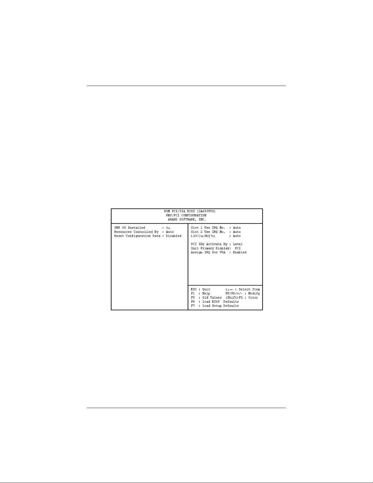
BIOS Setup
Serial Port
When enabled, this item allows the system to reset power management timer when
system activity at the serial port is detected. The options are: Enabled (default);
Disabled.
Parallel Port
When enabled, this item allows the system to reset power management timer when
system activity at the parallel port is detected. The options are: Disabled (default);
Enabled.
PNP/PCI Configuration Setup
The “PNP and PCI Setup” option configures the PCI Bus slots. All PCI Bus slots on
the system use INTA#, thus all installed PCI cards must be set to this value.
PNP OS Installed
When Plug and Play operating systems (OS) are installed, interrupts may be
reassigned by the OS when Yes is selected. When a non-Plug and Play OS is installed
or to prevent reassigning of interrupt settings, select No here. The options are: No
(default); Yes.
Resources Controlled By
If set at Auto, BIOS automatically arranges all system resources for you. If there are
conflicts or you are not satisfied with the configuration settings, simply set all the
resources by selecting Manual. The options are: Auto (default); Manual.
Reset Configuration Data
51
Page 67

SAHARA System User Guide
When Enabled, this feature allows the system to clear the last BIOS configuration
data and reset them with the default BIOS configuration data. The options are:
Disabled (default); Enabled.
IRQ-3; -4; -5; -7; -9; -10; -11; -12; -14; -15; DMA-0; -1; -3; -5; -6; -7
Assigned to (available only if Resources Controlled By is set at Manual)
These options allow you to set whether a particular IRQ# or DMA# is used by a
PCI/ISA PNP or Legacy ISA card. The options are: PCI/ISA PNP (default); Legacy
ISA.
Slot 1/2 Use IRQ No.
These options allow you to set how IRQ use is determined for each PCI slot. The
default setting for each field is Auto, which uses auto-routing to determine IRQ use.
The options are: Auto (default), 3, 4, 5, 7, 9, 10, 11, 12, 14, 15.
LAN Use IRQ No.
This option allow you to set how IRQ use is determined for the onboard integrated
PCI-based Intel 82558 Ethernet LAN controller. The default setting for this field is
Auto, which uses auto-routing to determine IRQ use. The options are: Auto (default),
3, 4, 5, 7, 9, 10, 11, 12, 14, 15.
PCI IRQ Activated By
If the IDE card is triggered by edge, set it at Edge. The options are: Level (default);
Edge.
Init Primary Display
This feature allows you to set the primary graphics adapter used in the system. The
options are: PCI (default), AGP.
Assign IRQ For VGA
If the onboard RAGE IIC/PRO AGP chip you are using does not need an IRQ, select
Disabled, thereby releasing an IRQ for system use. The options are: Enabled
(default), Disabled.
Used MEM Base Addr (available if Resources Controlled By is set at
Manual)
This field allows you to set the base address and block size of a Legacy ISA card that
uses any memory segment within the C800, CC00, D000, D400, D800, and DC00
address range. If you have such a card, and you are not using an ICU to specify its
address range, select a base address from the six available options and the next field
will then appear for selecting the block size. The options are: N/A (default); C800;
CC00; D000; D400; D800; DC00.
Used MEM Length (available if Used MEM Base Addr is not set at N/A)
52
Page 68
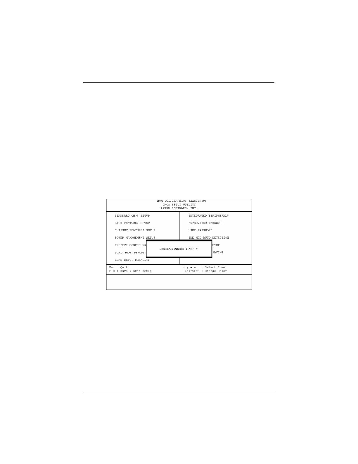
BIOS Setup
If you have more than one Legacy ISA card in the system that requires to use the
aboved address range, you can increase the block size to either 8K, 16K, 32K, or
64K. If you are using an ICU to accomplish this task, leave the aboved option Used
MEM Base Addr at N/A. The options are: 8K (default); 16K; 32K; 64K.
Load BIOS Defaults
The “Load BIOS Defaults” option allows you to load the troubleshooting default
values permanently stored in the BIOS ROM. These default settings are non-optimal
and disable all high performance features. To load these default settings, highlight
“Load BIOS Defaults” on the main screen and then press the <Enter> key. The
system displays a confirmation message on the screen. Press the <Y> key and then
the <Enter> key to confirm. Press the <N> key and then the <Enter> key to abort.
This feature does not affect the fields on the Standard CMOS Setup screen.
Load Setup Defaults
The “Load Setup Defaults” option allows you to load the default values to the system
configuration fields. These default values are the optimized configuration settings for
the system. To load these default values, highlight “Load Setup Defaults” on the
main screen and then press the <Enter> key. The system displays a confirmation
message on the screen. Press the <Y> key and then the <Enter> key to confirm.
Press the <N> key and then the <Enter> key to abort. This feature does not affect the
fields on the Standard CMOS Setup Screen.
53
Page 69

SAHARA System User Guide
Integrated Peripherals
USB Controller
Disable this option if you are not using the onboard USB feature. The options are:
Enabled (default); Disabled.
54
Page 70

BIOS Setup
BIOS Support USB Keyboard (available only when USB Controller is
enabled)
When the USB devices cannot be detected automatically by the system BIOS or some
driver diskettes came with the USB devices, set it at DOS to allow for the installation
of the drivers. The options are: Setup (default); DOS.
Onboard FDC Controller
When Enabled, the floppy disk drive (FDD) controller is activated. The options are:
Enabled (default); Disabled.
Onboard Serial Port 1
If serial port 1 uses the onboard I/O controller, you can modify the serial port
parameters. If an I/O card needs to be installed, COM3 and COM4 maybe needed.
The options are: 3F8/IRQ4 (default); Disabled; 3E8/IRQ4; 2F8/IRQ3; 2E8/IRQ3.
Onboard Serial Port 2
If serial port 2 uses the onboard I/O controller, you can modify the serial port
parameters. If an I/O card needs to be installed, COM3 and COM4 may be needed.
The options are: 2F8/IRQ3 (default); Disabled; 3E8/IRQ4; 2E8/IRQ3; 3F8/IRQ4.
Onboard Parallel Port
Allows you to select from a given set of parameters if the parallel port uses the
onboard I/O controller. The options are: 378/IRQ7 (default); Disabled; 278/IRQ5;
3BC/IRQ7.
Parallel Port Mode (available if Onboard Parallel Port is not set at
Disabled)
Allows you to connect with an advanced printer. The options are: ECP (default);
EPP; SPP; ECP+EPP.
ECP Mode Use DMA (available if Parallel Port Mode is set at ECP or
ECP+EPP)
This feature allows you to select the Direct Memory Access (DMA) channel. The
options are: 3 (default); 1.
55
Page 71

SAHARA System User Guide
Supervisor Password and User Password
These two options set the system passwords. “Supervisor Password” sets a password
that will be used to protect the system and the Setup utility; “User password” sets a
password that will be used exclusively on the system. By default, the system comes
without any passwords. To specify a password, highlight the type you want and then
press the <Enter> key. A password prompt appears on the screen. Taking note that
the password is case sensitive, and can be up to 8 alphanumeric characters long, type
in your password and then press the <Enter> key. The system confirms your
password by asking you to type it again. After setting a password, the screen
automatically reverts to the main screen.
To implement the password protection, specify in the “Security Option” field of the
BIOS Features Setup screen when the system will prompt for the password. If you
want to disable either password, press the <Enter> key instead of entering a new
password when the “Enter Password” prompt appears. A message confirms the
password has been disabled.
IDE HDD Auto Detection
The “IDE HDD Auto Detection” option detects the parameters of an IDE hard drive
and automatically enters them into the Standard CMOS Setup screen. To accept the
optimal entries, press the <Y> key or else select from the numbers displayed under
the OPTIONS field. If you accept the values, the parameters will appear listed beside
the drive letter on the screen. The process then proceeds to the next drive letter.
Pressing the <N> key to skip rather than to accept a set of parameters causes the
program to enter zeros after that drive letter.
When auto-detection is completed, the program automatically enters all entries you
accepted on the field for that drive in the Standard CMOS Setup screen. Skipped
entries are ignored and are not entered in the screen.
If you are auto-detecting a hard drive that supports the LBA mode, three lines will
appear in the parameter box. Choose the line that lists LBA for an LBA drive. Do not
select Large or Normal.
The auto-detection feature can only detect one set of parameters for a particular IDE
hard drive. Some IDE drives can use more than one set. This is not a problem if the
drive is new and there is nothing on it.
56
Page 72
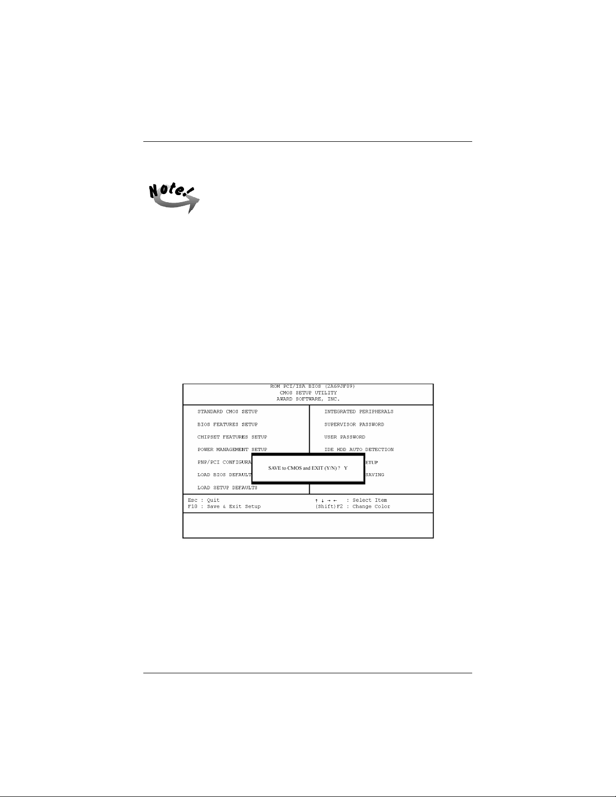
BIOS Setup
If the hard drive was already formatted on an older previous
system, incorrect parameters may be detected. You will need to
enter the correct parameters manually or use low-level format if
you do not need the data stored on the hard drive.
If the parameters listed differ from the ones used when the drive was formatted, the
drive will not be readable. If the auto-detected parameters do not match the ones that
should be used for your drive, do not accept them. Press the <N> key to reject the
presented settings and enter the correct ones manually from the Standard CMOS
Setup screen.
Save and Exit Setup
Select this option to save into the CMOS memory all modifications you specified
during the current session. To save the configuration changes, highlight the “Save &
Exit Setup” option on the main screen and then press the <Enter> key.
57
Page 73
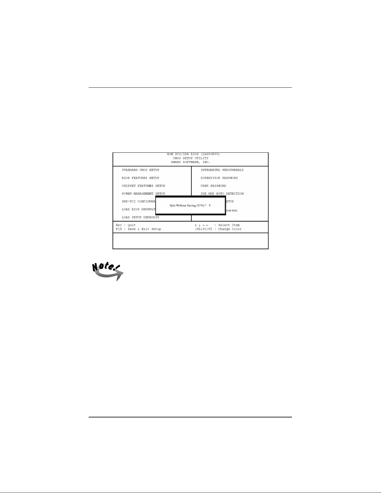
SAHARA System User Guide
Exit Without Saving
Select this option to exit the Setup utility without saving the modifications you
specified during the current session. To exit without saving, highlight the “Exit
Without Saving” option on the main screen and then press the <Enter> key.
58
Default values of the various Setup items on this chapter may not
be the same ones shown on the monitor screen.
Page 74

TROUBLESHOOTING
The system is built to last long and perform its multi-functions with utmost efficiency. It is also user-friendly, both in its normal operations and when it encounters a system problem. It alerts you to possible problems by way of screen
messages that also give you the correct instructions to solve the problem.
This chapter offers some possible solutions to potential problems that you
might have with the computer.
Determining Problem Causes
To facilitate troubleshooting when encountering problems while operating the
computer, it is important to find out if the cause is software-related or hardware-related. It is suggested that you record the observations of events immediately prior to and during the time you encounter the problem.
If the problem is software-related, consult the software manual of the application you are using. If the problem is hardware-related, it may be due to improper installation and/or incorrect configuration. If it is due to improper
installation, then any or a combination of the following corrective procedures
should solve the problem:
Chapter 5
n Check the installation or connection to see if it is correctly done or firmly
in place.
n Check if the installation calls for a change in jumper settings or DIP
switch settings.
n Read the document accompanying the hardware option you installed for
any special instructions or troubleshooting actions.
59
Page 75

SAHARA System User Guide
BIOS-Related Errors
When BIOS detects an error during system startup or during POST (Power-OnSelf-Test), the display monitor normally shows the message that tells the cause
of the problem and also suggests on how to solve it. These kinds of error messages will ask you to run Setup and correct the settings in that program according to actual configuration. (Please read Chapter 4 on BIOS Setup.)
The following information lists some of the common configuration-related errors and gives the corresponding procedures to solve them.
Error Message: CMOS BATTERY HAS FAILED
Cause: The CMOS battery is no longer functional.
Action: Replace it.
Error Message: CMOS CHECKSUM ERROR
Cause: BIOS checksum of CMOS is incorrect. This may be caused by a weak battery.
Action: Check the battery and replace it, if necessary.
Error Message: DISK BOOT FAILURE, INSERT SYSTEM DISK AND PRESS
ENTER
Cause: No boot device was found.
Action: Insert a system disk into Drive A and press <Enter> key. If you boot from the
hard disk, make sure that the controller is installed properly and all cables are
correctly attached.
Error Message: DISK DRIVES OR TYPES MISMATCH ERROR – RUN SETUP
Cause: The type of disk drive installed in the system is different from that defined in
CMOS.
Action: Run Setup to reconfigure disk drive type.
Error Message: DISPLAY SWITCH IS SET INCORRECTLY
Cause: Display switch on the mainboard is set at color. This message indicates a differ-
ent switch setting than indicated in Setup.
Action: First, determine the correct setting; then either change the jumper setting, or run
Setup to re-select a proper video option.
60
Page 76

Troubleshooting
Error Message: DISPLAY TYPE HAS CHANGED SINCE LAST BOOT
Cause: Since the last power-on of the system, the display adapter has changed.
Action: Run Setup to re-select a proper video option.
Error Message: ERROR ENCOUNTERED INITIALIZING HARD DRIVE
/ ERROR INITIALIZING HARD DISK CONTROLLER
Cause: Hard disk cannot be initialized.
Action: Ensure that the hard disk controller is installed properly and all cables are prop-
erly connected. Ensure the correct hard disk type is set in the BIOS Setup.
Check that if any jumper related to the hard disk needs to be reconfigured.
Error Message: FLOPPY DISK CNTRLR ERROR
/ NO CNTRLR ERROR / NO CNTRLR PRESENT
Cause: Cannot find or initialize the floppy disk drive (FDD) controller.
Action: Ensure that the FDD controller is installed properly. If no floppy disk drive is
installed, run Setup and set the Diskette Drive at NONE.
Error Message: KEYBOARD ERROR / NO KEYBOARD PRESENT
Cause: Cannot initialize the keyboard.
Action: Make sure the keyboard is attached properly and that no keys are being pressed
during boot.
Error Message: MEMORY SIZE HAS CHANGED SINCE LAST BOOT
Cause: Memory has been added or removed since last bootup but system has not recog-
nized it.
Action: Run Setup and enter the new memory size in the memory fields.
Error Message: MEMORY VERIFY AT . . .
Cause: Indicates an error verifying a value already written to memory.
Action: Use the specified location along with the system’s memory map to locate the bad
chip.
Error Message: PRESS A KEY TO REBOOT
Cause: This message is displayed when an error occurs that requires you to reboot.
Action: Press any key so that the system will reboot.
61
Page 77

SAHARA System User Guide
Error Message: PRESS F1 TO DISABLE NMI, F2 TO REBOOT
Cause: BIOS detects a Non-Maskable Interrupt condition.
Action: Press F1 to disable NMI or F2 to reboot the system without disabling NMI.
Error Message: RAM – CHECKING FOR SEGMENT . . .
Cause: Indicates an error in the RAM module.
Action: Change the malfunctioning RAM module.
Error Message: SYSTEM HALTED, (CTRL–ALT–DEL) TO REBOOT
Cause: Indicates the present boot attempt has been aborted and the system must be re-
booted.
Action: Press <CTRL> + <ALT> + <DEL> keys simultaneously.
62
Page 78

SYSTEM SPECIFICATIONS
Product Features
Key features of the SAHARA System include:
n Mainboard Chipset Architecture
Intel 440LX(EX) AGPset
n Processors
The onboard Retention Mechanism supports:
Intel Pentium® II CPU speed 233/266/300/333MHz processors
Intel Celeron™ CPU speed 266/300/333MHz processors
Intel Mendocino™ CPU speed 300/333MHz processors
n Onboard LAN Controller
Integrated PCI-based Intel 82558 10/100Mbps Ethernet controller
n Onboard VGA Controller
Integrated AGP-based ATI RAGE IIC/PRO AGP controller with onboard
2MB SGRAM (upgradable to 8MB)
n Onboard Audio Controller
Integrated ISA-based CrystalClear™ CS4235 3D audio
Sound Blaster™, Sound Blaster Pro™ and Windows Sound System™
compatible
n BIOS (Basic Input Output System)
AWARD BIOS with 2MB Flash EEPROM, DMI 2.0 compliant
n Floppy Disk Drive
3.5-inch Slim 1.44MB (Megabytes) capacity
n Hard Disk Drive (Optional)
3.5-inch Ultra DMA/33 S.M.A.R.T. HDD up to 12GB
Appendix A
63
Page 79

SAHARA System User Guide
n System Memory
Supports up to 256MB SDRAM or EDO DRAM via two 168-pin DIMM
sockets, including ECC memory
n Cache Memory
Supports 512KB ultra-fast Level II cache on CPU cartridge
n Riser Card
One PCI slot and one shared PCI/ISA slot
The maximum card cage load should not exceed +5V, 1A; +12V,
1A in combination.
n Input/Output Interface
Two serial ports, one parallel port with ECP/EPP, two USB ports, one
RJ45 LAN connector, two PS/2 connectors, one D-sub 15-pin female
VGA port, one optional Game port, one optional IrDA port, one Mic-in;
one Line-in; one Line-out for Audio
n CD-ROM Drive
12.7mm Slim 20X/24X CD-ROM or DVD-ROM drive
Technical Specifications
n Dimensions
310(L) x 300(H) x 88(W) mm
n Power Supply
100 to 240 VAC (Universal input), 85 Watt or
115/230 VAC, 90 Watt
n Environment Air Temperature
Operating: 5 oC to 35 oC / Storage: –29 oC to 65 oC
n System Operating Environment
The recommended system operating room temperature is between 50C and
350C. In the event that the system is to function as a workstation or server,
it is imperative that periodic inspection of the CPU fan and the power
supply fan be undertaken. Please consult the local dealer for more information.
n Humidity
Operating: 0 % to 80 % / Storage: 0 % to 95 %
64
Page 80

Appendix B
INSTALLATION PROCEDURES
The SAHARA System has several user-adjustable jumpers on the mainboard that
allow you to configure the system to suit your requirements. This chapter contains
information on the various jumper settings on the mainboard.
To set up your computer, you must complete the following steps:
n Step 1 -
Set system jumpers
n Step 2 -
Install system RAM modules
n Step 3 -
Install the Central Processing Unit (CPU)
n Step 4 -
Install expansion cards
n Step 5 -
Connect ribbon cables, cabinet wires, and power supply
n Step 6 -
Set up BIOS software (see Chapter Four)
n Step 7 -
Set up supporting software tools (see Appendix C)
65
Page 81
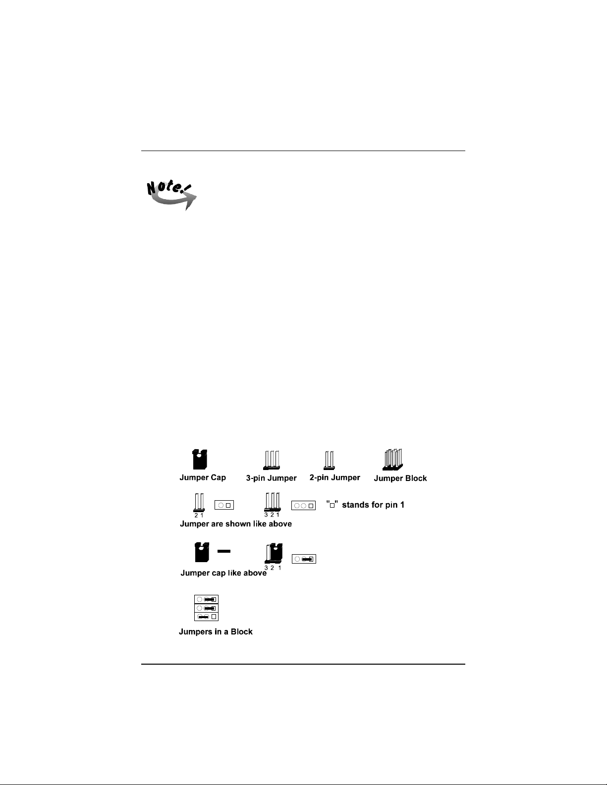
SAHARA System User Guide
Excessive torque may damage the mainboard. When using an
electric screwdriver on the mainboard, make sure that the torque is
set to the allowable range of 5.0 ~ 8.0kg/cm.
Mainboard components contain very delicate Integrated Circuit
(IC) chips. To prevent static electricity from harming any of the
mainboard’s sensitive components, you should follow some
precautions whenever working on the computer:
1. Unplug the computer when working on the inside.
2. Hold components by the edges and try not to touch the IC chips,
leads, or circuitry.
3. Wear an anti-static wrist strap which fits around the wrist.
4. Place components on a grounded anti-static pad or on the bag
that came with the component whenever the components are
separated from the system.
1). Set System Jumpers
Jumpers are used to select the operation modes for your system. Some jumpers on the
board have three metal pins with each pin representing a different function. A “1” is
written besides pin 1 on jumpers with three pins. To set a jumper, a black cap
containing metal contacts is placed over the jumper pin/s according to the required
configuration. A jumper is said to be shorted when the black cap has been placed on
one or two of its pins. The types of jumpers used in this manual are shown below:
66
Page 82

Mainboard Installation Procedures
Users are not encouraged to change the jumper settings not listed
in this manual. Changing the jumper settings improperly may
adversely affect system performance.
Components That Concern Installation
67
Page 83
SAHARA System User Guide
ONBOARD MARK MEANING PAGE
CMOS_CLR Clear CMOS Data 69
EP1, EP2 Flash ROM Type Select 69
FREQ CPU to Bus Frequency Ratio Select 75
DIMM1, DIMM2 DIMM Memory Module Support 70
SL1 EISA Bus Expansion Slot (32-bit) 75
SLOT1 Central Processing Unit (CPU) Cartridge Support 72
AT_PWR ATX Power Connector 88
CD_ROM CD-ROM Drive Connector 87
COM1, COM2 Serial Port 79
CPU_FAN CPU Fan Connector 84
F_PNL Connectors for LEDs and Switches on Front Panel 87
FDD Floppy Diskette Drive Connector 85
GAME Joystick/MIDI Connector 83
HDD_PW Hard Disk Drive Power Connector 86
IR (option) Infrared Port Module 82
KB PS/2 Keyboard Connector 80
LAN RJ45 Connector 82
LINE_IN Audio Line-In Jack 81
LINE_OUT Audio Line-Out Jack 81
LPT Parallel Port 80
MIC_IN Audio Microphone Jack 81
MS PS/2 Mouse Connector 80
PRIMARY IDE Device Connector 86
USB Universal Serial Bus Connector 81
VGA VGA Connector 83
68
Page 84
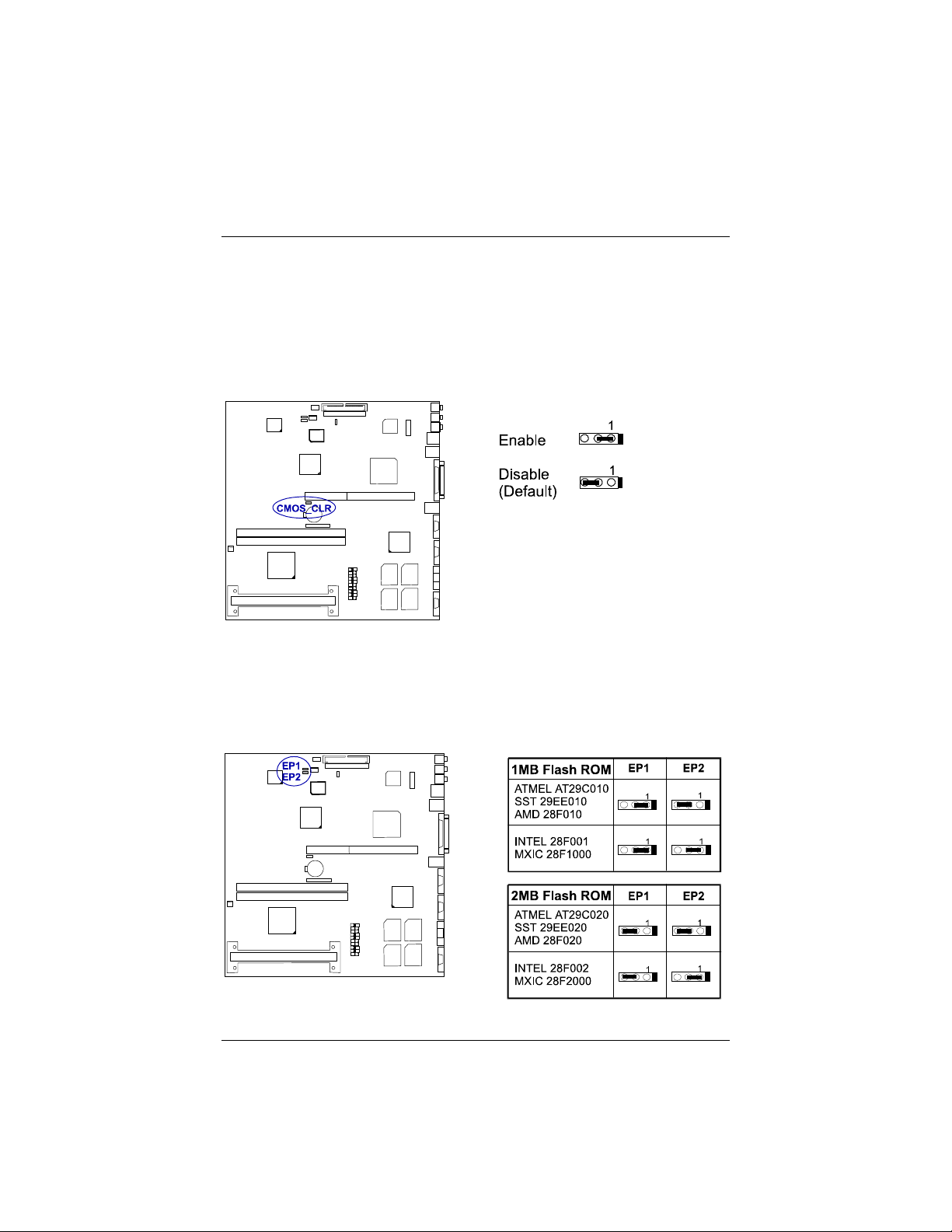
Mainboard Installation Procedures
CMOS Clear: CMOS_CLR
This jumper allows you to enable or to disable the CMOS clear feature. When set at
Enable, the original CMOS configuration will be replaced with whatever CMOS
parameters are being entered. When set at Disable, the original CMOS configuration
will not be affected. If you need to set the CMOS configuration, keep this jumper at
Enable.
Flash ROM Type Select: EP1, EP2
These two jumpers allow you to configure the flash ROM chip. This jumper setting
was installed with the manufacturer’s default. If you want to know the flash ROM
type installed on this mainboard, partially remove the sticker on top of the chip.
69
Page 85
SAHARA System User Guide
2). Install RAM Modules
SDRAM
The working space of the computer is the Random Access Memory (RAM). The
system cannot act upon data unless it is loaded into RAM. When more memory is
added, the working memory of the computer is larger, thereby increasing total
performance. The mainboard RAM is comprised of two 168–pin Dual In–line
Memory Modules (DIMMs). Each DIMM socket is able to support up to 128MB
lightning-fast SDRAM.
SDRAM is an advanced new memory technology that helps boost overall system
performance with its ability to synchronize all operations with the processor clock
signal. This makes the implementation of control interfaces easier, and speeds up
column access time. SDRAM features an on–chip burst counter that can be utilized to
increment column addresses for very fast burst access, which means that SDRAM
allows new memory access to be initiated before the preceding access has been
finished.
Before making DRAM upgrades you should verify the type and speed of the RAM
currently installed from your dealer. Installing mixtures of RAM types other than
those described in this manual will have unpredictable results.
RAM Module Configuration
The mainboard provides two onboard DIMM sockets allowing 3.3V (unbuffered)
SDRAM DIMM modules. Either 8, 16, 32, 64, or 128MB DIMM can be installed on
these two sockets. The maximum total memory supported is up to 256MB.
Memory Socket Memory Module Total Memory
DIMM Sockets 1&2
(DIMM1 & DIMM2)
70
8MB, 16MB, 32MB, 64MB, 128MB
168-pin 3.3V EDO/SDRAM DIMM
Total System Memory (Max 256MB) =
x2
Page 86
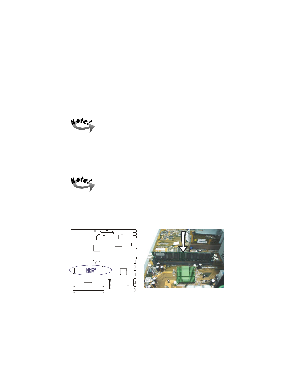
Mainboard Installation Procedures
Or one 256MB DIMM on either DIMM1 or DIMM2.
Memory Socket Memory Module Total Memory
DIMM Sockets 1/2
(DIMM1 or DIMM2)
256MB
168-pin 3.3V EDO/SDRAM DIMM
Total System Memory (Max 256MB) = 256MB
This mainboard supports DIMMs with access speeds of 10ns, 12ns,
and 15ns. ECC memory and parity check is also supported.
x1 256MB
Install DIMMs
SDRAM DIMM modules have different pin contact on each side and therefore have a
higher pin density. Complete the following procedures when installing DIMMs:
Do not use memory modules with more than 24 chips per module.
Modules with more than 24 chips exceed the design specifications
of the memory subsystem and will be unstable.
The notch on the DIMM module will shift between left, center, or
right to identify the type and also to prevent the wrong type from
being inserted into the DIMM slot on the mainboard. Ask your
retailer for the specifications before purchasing.
1. Locate the DIMM slots on the mainboard. (See the following figure.)
2. Install the DIMM straight down into the DIMM slot with both hands.
71
Page 87
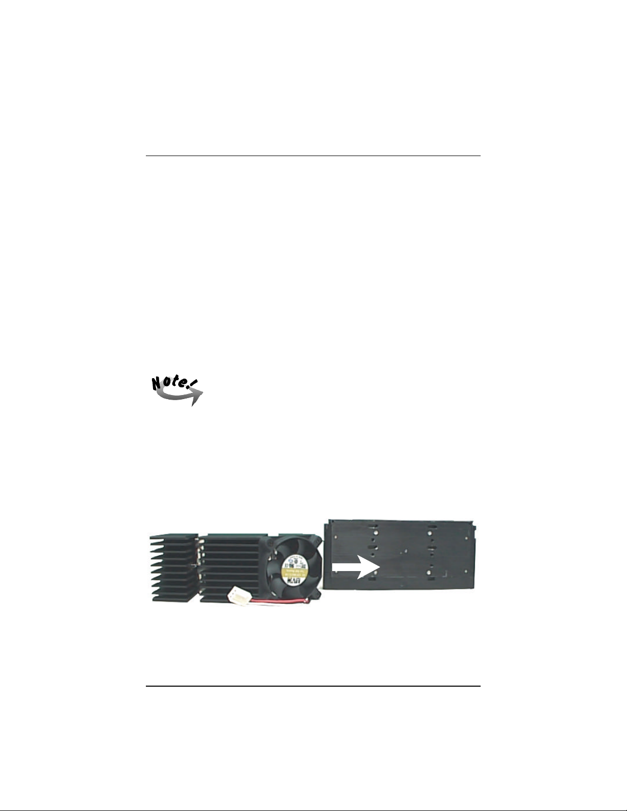
SAHARA System User Guide
3. The clip on both ends of the DIMM slot will close up to hold the DIMM in place
when the DIMM touches the slot’s bottom.
Remove DIMMs
Press the clips with both hands to remove the DIMM.
3). Install the Central Processing Unit (CPU)
If the mainboard is for the Pentium® II CPU, then it comes with an onboard
Retention Mechanism, a Heatsink with Fan, and two clips for attaching the Heatsink
with Fan to the CPU cartridge. If any piece is missing, please contact your local
system dealer to help you. If the mainboard is for the Celeron™ CPU, then it comes
with an onboard Retention Mechanism, a Passive Heatsink, and a clip for attaching
the Passive Heatsink to the CPU.
The Retention Mechanism is already installed onboard by the
manufacturer.
CPU Cartridge and Heatsink with Fan Installation (for
Pentium® II CPU)
To install the CPU cartridge and Heatsink with Fan, refer to the following steps:
1. Peel off the backing tape located on the flat side of the Heatsink with Fan.
2. Carefully position the Heatsink with Fan on the center of the CPU cartridge, taking
care to align the two protruding knobs of the Heatsink with Fan to the holes on the
thermal plate side of the CPU cartridge, with the fan on the right side facing you.
72
Page 88
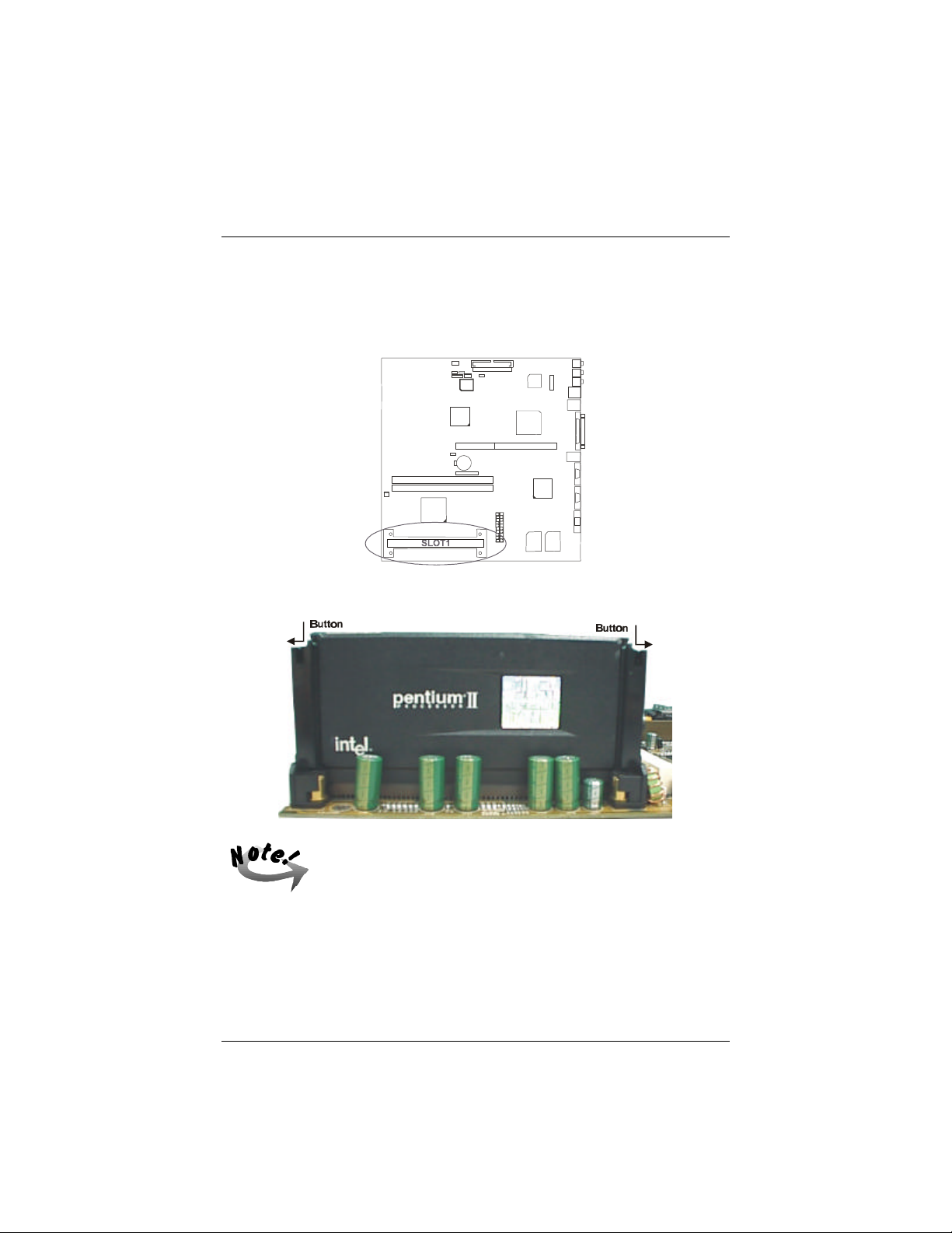
Mainboard Installation Procedures
3. Push in both ends of each of the heatsink clip into the CPU cartridge thereby,
fixing the Heatsink with Fan onto the CPU cartridge.
4. Slide the CPU module together with the heatsink into the Retention Mechanism
Assembly located on SLOT1 of the mainboard.
5. Press the buttons on either end of the CPU module.
If the Heatsink with Fan is not mounted tightly against the CPU
cartridge, the CPU will overheat.
6. Plug the heatsink fan power cord into the CPU_FAN connector on the mainboard.
73
Page 89
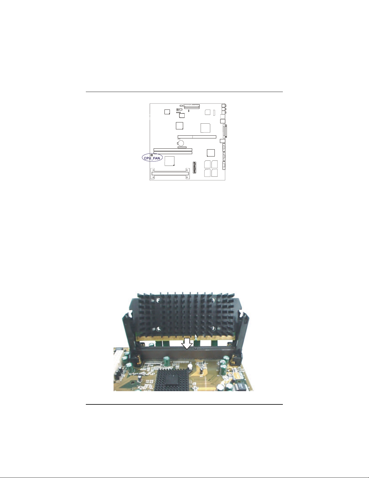
SAHARA System User Guide
CPU and Passive Heatsink Installation (for Celeron™
CPU)
To install the CPU and Passive Heatsink, refer to the following steps:
1. Peel off the backing tape located on the flat side of the Passive Heatsink.
2. Carefully position the Passive Heatsink on the center of the front of the CPU, and
on its backside, push in both ends of the heatsink clip taking care to align it to the
holes of the CPU thereby, fixing the Passive Heatsink onto the CPU.
3. Slide the CPU together with the Passive Heatsink into the Retention Mechanism
Assembly located on SLOT1 of the mainboard.
74
Page 90
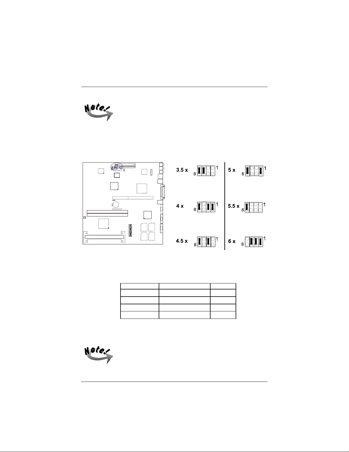
Mainboard Installation Procedures
If the Passive Heatsink is not mounted tightly against the CPU
cartridge, the CPU will overheat.
CPU to Bus Frequency Ratio: FREQ
This jumper is used set the ratio of the internal frequency of the CPU to the bus
clock.
Intel Pentium II CPUs
FREQUENCY BUS FREQUENCY RATIO
333 MHz 66 MHz 5 x
300 MHz 66 MHz 4.5 x
266 MHz 66 MHz 4 x
233 MHz 66 MHz 3.5 x
4). Install Expansion Cards
Make sure to unplug the power supply when adding or removing
expansion cards or other system components. Failure to do so may
cause severe damage to both the mainboard and expansion cards.
75
Page 91
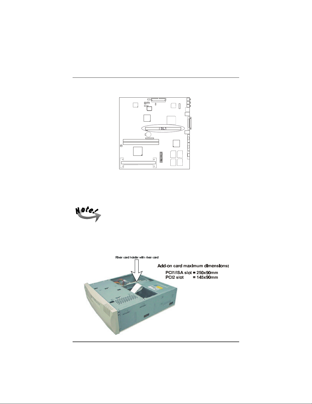
SAHARA System User Guide
The mainboard features one 32-bit EISA bus expansion slot.
This section describes how to connect an expansion card to the system's riser card.
An expansion card is a printed circuit board that, when connected to the mainboard,
allows you to increase the capabilities of the system. For example, expansion cards
can provide video and sound capabilities.
Always turn the system power off before installing or removing any
device. Always observe static electricity precautions. See
“Handling Precautions” at the start of this manual.
To install an expansion card, follow the steps below:
1. Remove the computer chassis cover (see Chapter 3 “Removing the Chassis
Cover”) and locate the riser card on the EISA expansion slot (SL1).
76
Page 92
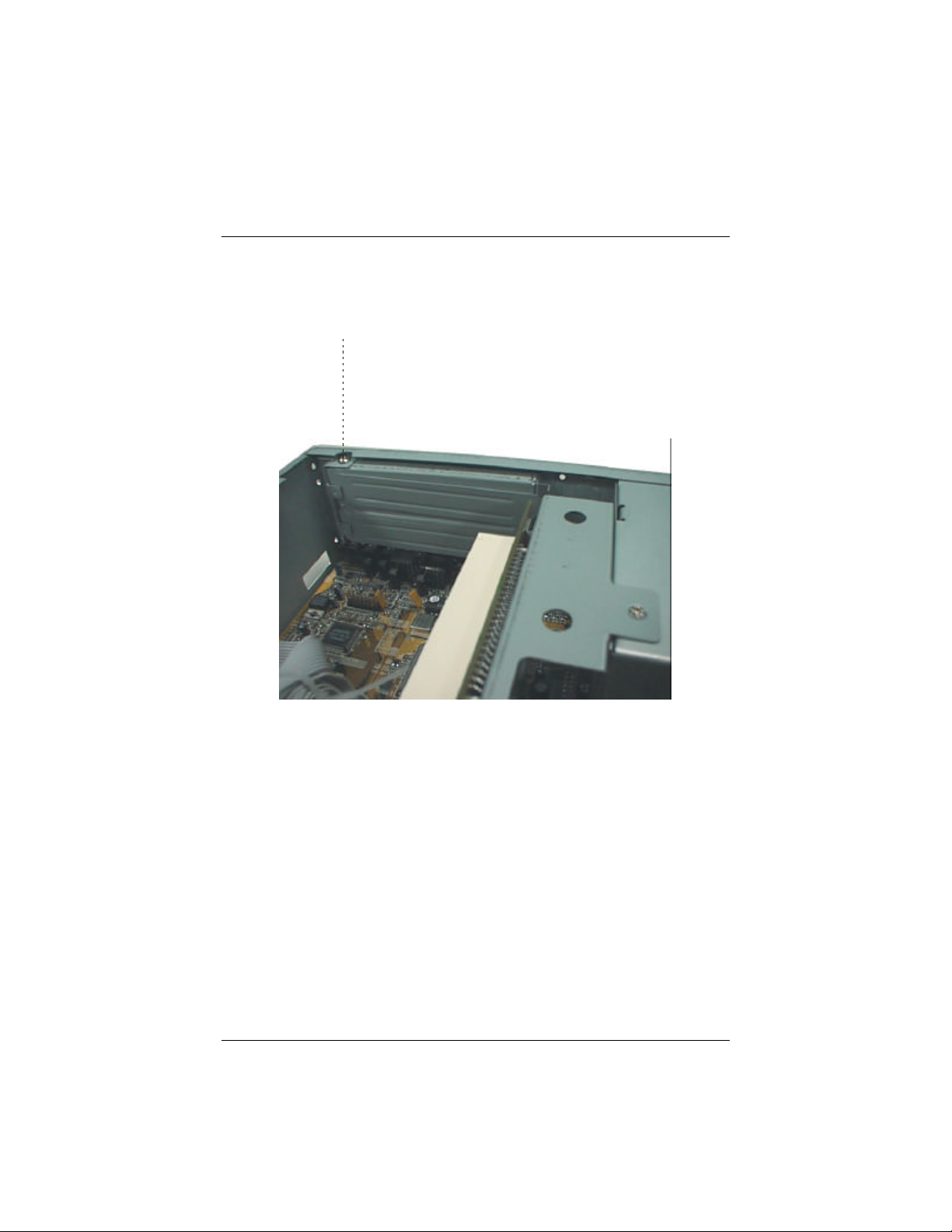
Mainboard Installation Procedures
2. Remove the corresponding slot cover from the computer chassis. Unscrew the
mounting screw that secures the slot cover and swing open the slot holder
securing plate prior to pulling the slot cover out from the computer chassis. Keep
the slot cover mounting screw nearby.
3. Read the expansion card documentation on any hardware and software settings that
may be required to setup the specific card.
4. Set any necessary jumpers on the expansion card.
5. Select an empty expansion slot on the riser card.
6. Holding the edge of the peripheral card, carefully align the edge connector with the
expansion slot.
7. Push the card firmly into the slot. Push down on one end of the expansion card,
then the other. Use this “rocking” motion until the add–on card is firmly seated
inside the expansion slot.
77
Page 93
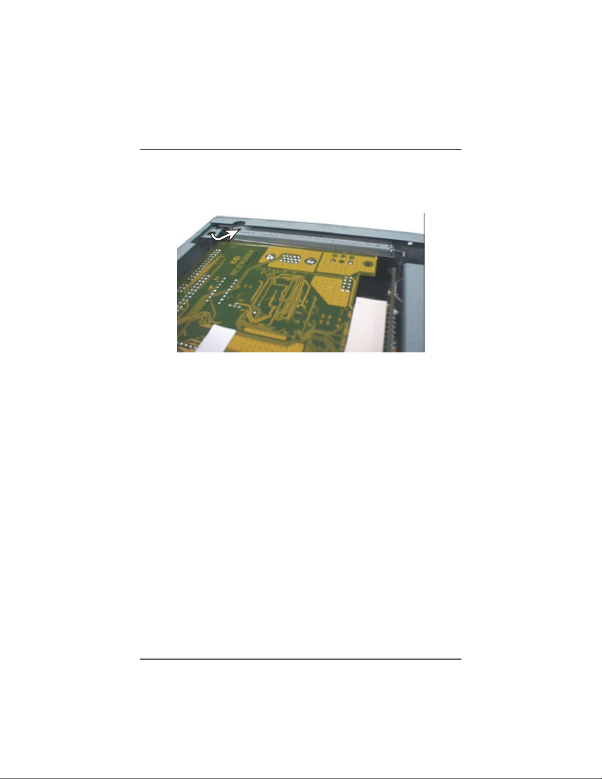
SAHARA System User Guide
8. Swing close the slot holder securing plate and secure the board with the mounting
screw removed in Step 2. Make sure that the card has been placed evenly and
completely into the expansion slot.
9. Replace the computer system’s cover. (See Chapter 3 “Re-installing the Chassis
Cover”.)
10. Setup the BIOS if necessary.
11. Install the necessary software drivers for the expansion card.
78
Page 94
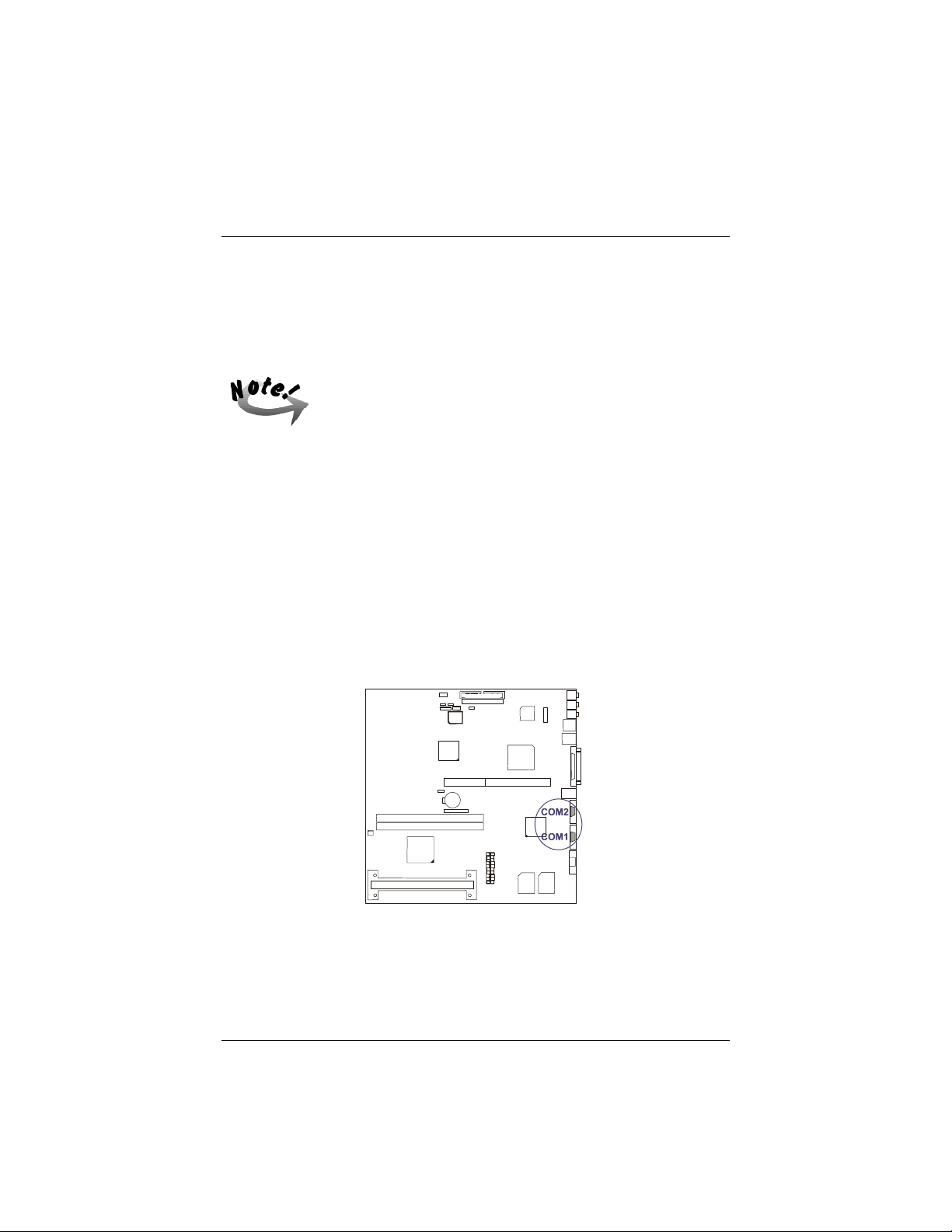
Mainboard Installation Procedures
5). Connect Cables and Power Supply
Connectors
Some pins are used for connectors or power sources. These are
clearly separated from jumpers. Placing jumper caps over these
will cause damage to the mainboard.
Ribbon cables should always be connected with the red stripe on the Pin 1 side of the
connector. The four corners of the connectors are labeled on the mainboard. Pin 1 is
the side closest to the power connector on hard drives and floppy drives.
Connectors allow the mainboard to link electronically with other parts of the system.
Some malfunctions encountered may be caused by loosed or improper connections.
Ensure that all connections are in place and firmly attached.
Serial Port Connectors: COM1, COM2
These two 9–pin D-sub male connectors allow you to connect with your devices that
use serial ports, such as a serial mouse or a modem. Usually, it is recommended to
connect the serial mouse to COM1 and the fax/modem to COM2.
79
Page 95
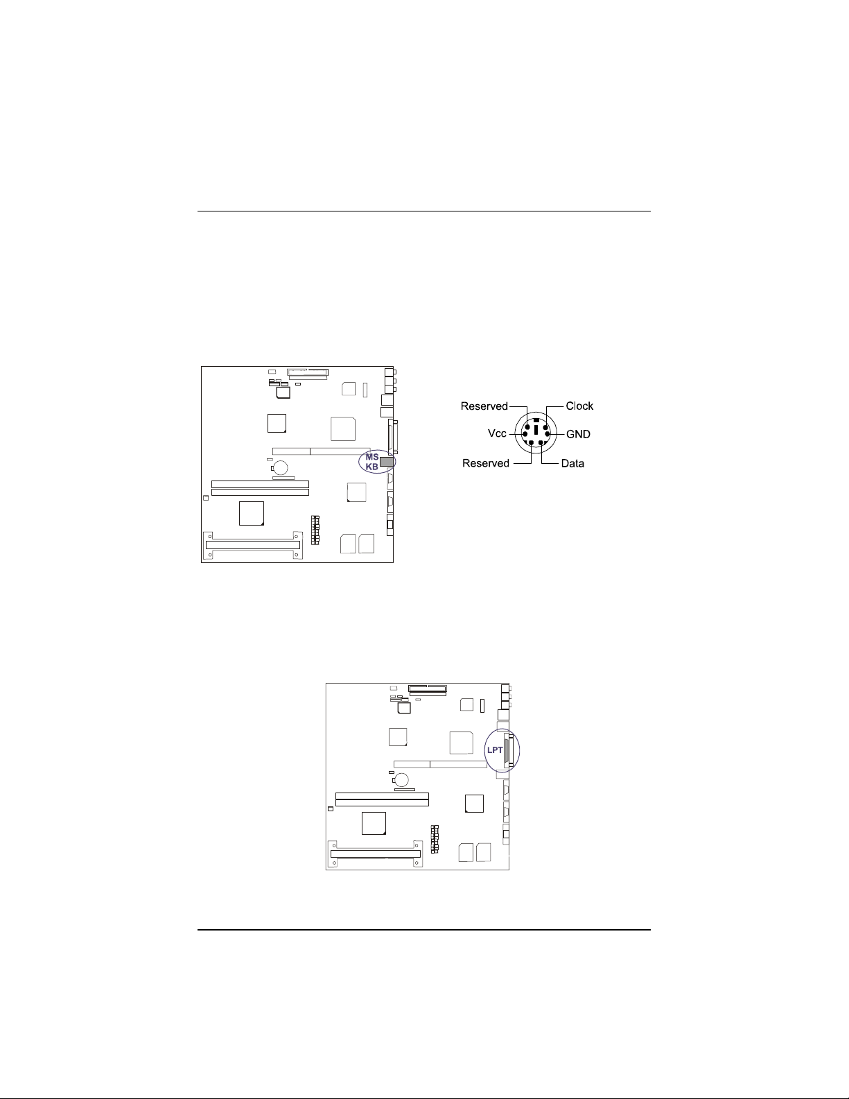
SAHARA System User Guide
PS/2 Keyboard and Mouse Connector: MS, KB
These two 6–pin female connectors are used for your PS/2 keyboard and PS/2 mouse.
The PS/2 keyboard connector is for a standard keyboard using a PS/2 plug (mini
DIN). This connector will not allow standard AT size (large DIN) keyboard plugs.
You may use a DIN to mini DIN adapter on standard AT keyboards.
The system will direct IRQ12 to the PS/2 mouse if one is detected. If not detected,
expansion cards may be using IRQ12.
Printer Connector: LPT
This 25–pin D-sub female connector is attached to your printer. Serial printers must
be connected to the serial port.
80
Page 96
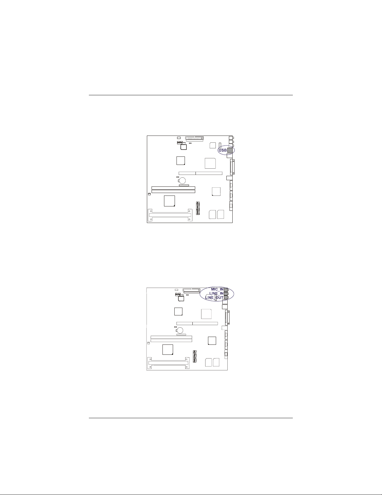
Mainboard Installation Procedures
Universal Serial Bus Connectors: USB
These two connectors are used for linking with USB peripheral devices.
Audio Port Connectors: LINE_OUT, LINE_IN, MIC_IN
LINE_OUT can be connected to headphones or preferably powered speakers.
LINE_IN allows tape players or other audio sources to be recorded by your computer
or played through the LINE_OUT. MIC_IN allows microphones to be connected for
inputing voice.
81
Page 97
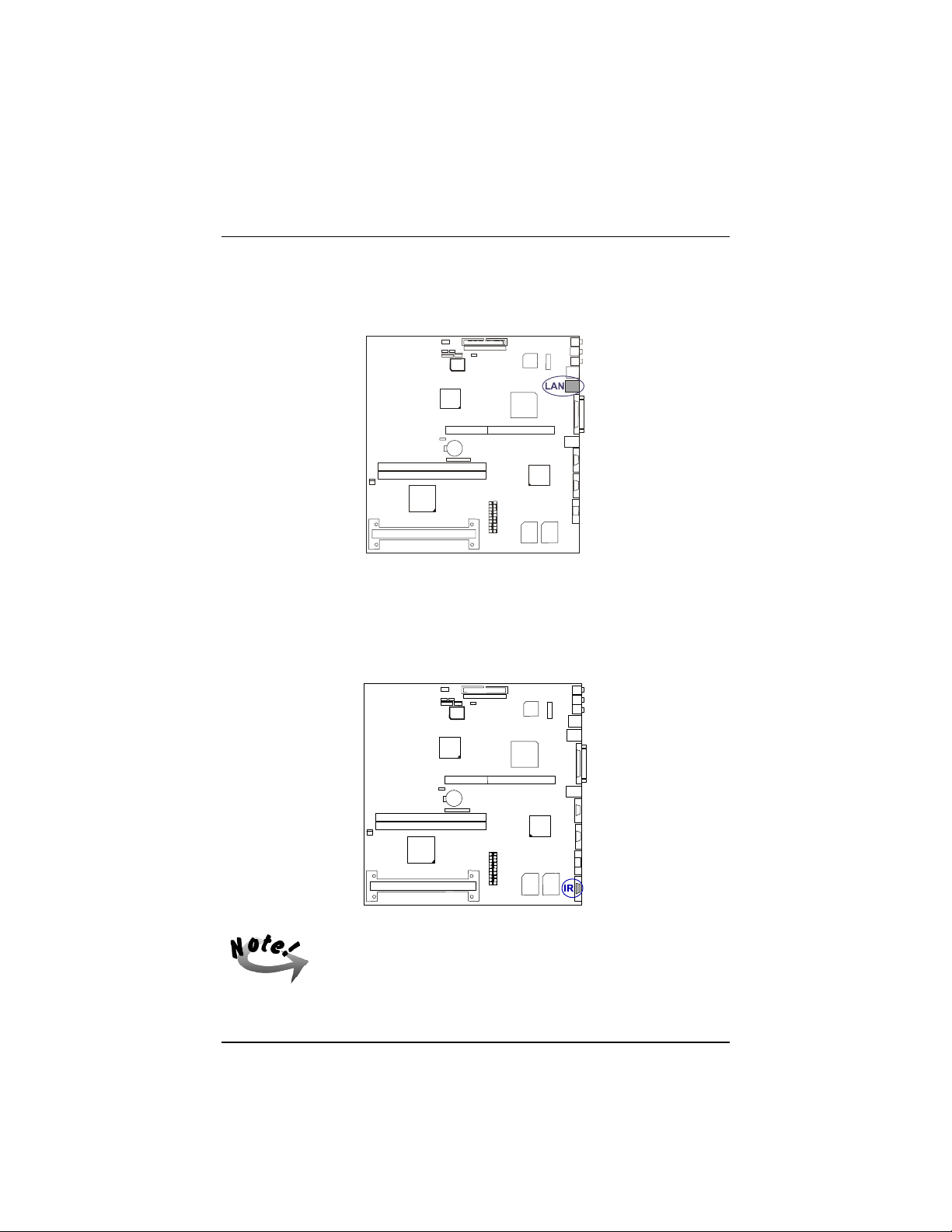
SAHARA System User Guide
RJ45 Connector: LAN
This connector allows you to connect to the LAN cable for network connections.
Infrared Connector: IR (optional)
This 9-hole D-sub female infrared (SIR) port allows transmission of data to another
system which also supports the IR feature.
82
Your system may or may not have this connector.
Page 98
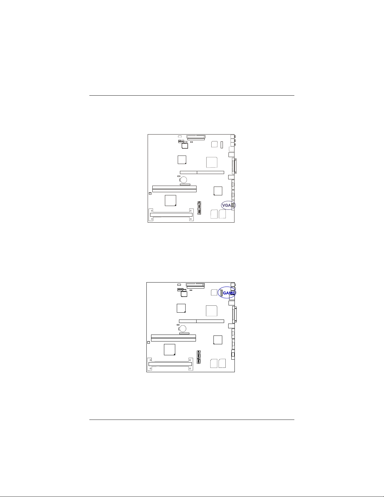
Mainboard Installation Procedures
VGA Connector: VGA
The 15-hole D-sub female connector is linked to the VGA monitor by a cable.
Joystick/MIDI Connector: GAME
This 16-pin male connector allows you to connect a 15-hole female D-sub game port
adapter cable which in turn allows you to use game joysticks or game pads for
playing games. Connect MIDI devices for playing or editing audio.
83
Page 99
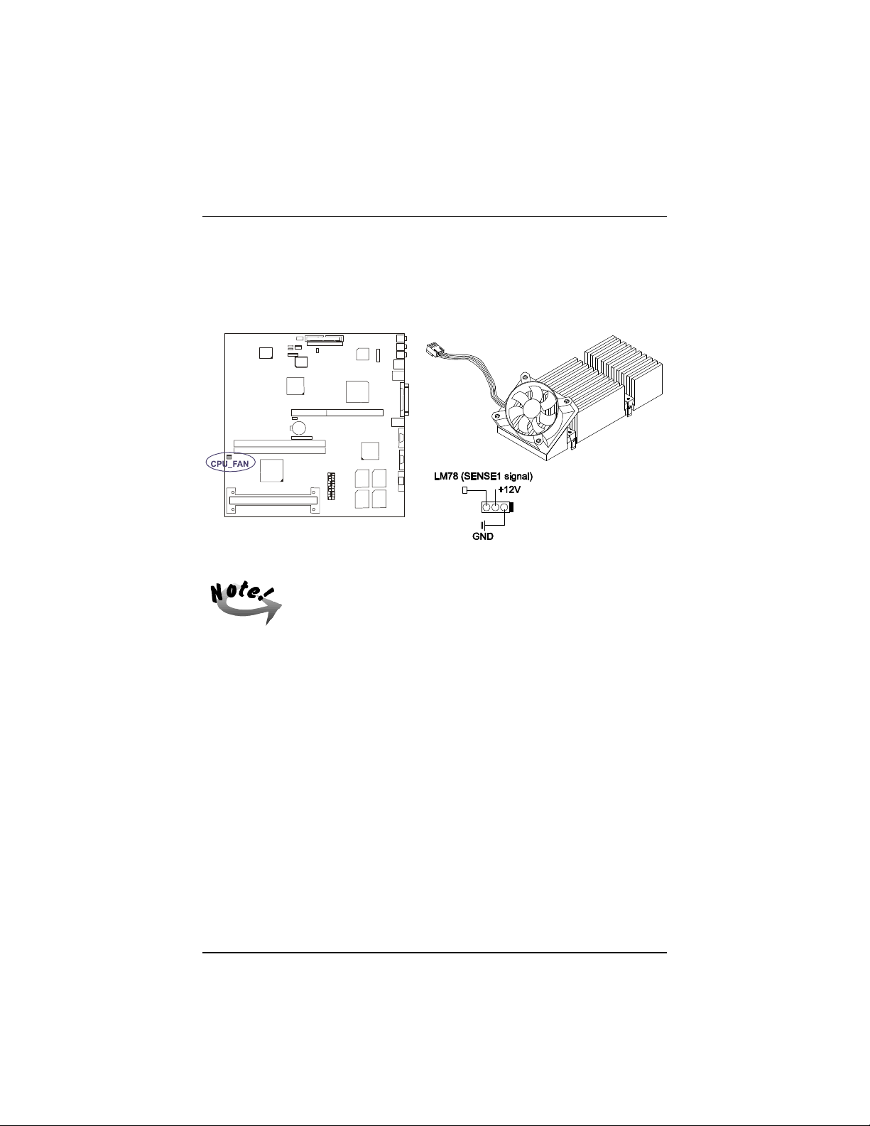
SAHARA System User Guide
CPU Fan Connector: CPU_FAN
This connector is linked to the CPU fan. When the system is in suspend mode, the
CPU fan will turn off; when it reverts back to full–on mode, the fan will turn back
on. The picture below shows the type of CPU fan with heatsink for your system.
Without sufficient air circulation, the Pentium® II CPU
cartridge may overheat and cause damage to both the CPU
cartridge and the mainboard.
Damage may occur to the mainboard and/or the CPU fan if
these pins are incorrectly used. These are not jumpers, do
not place jumper caps over these pins.
84
Page 100
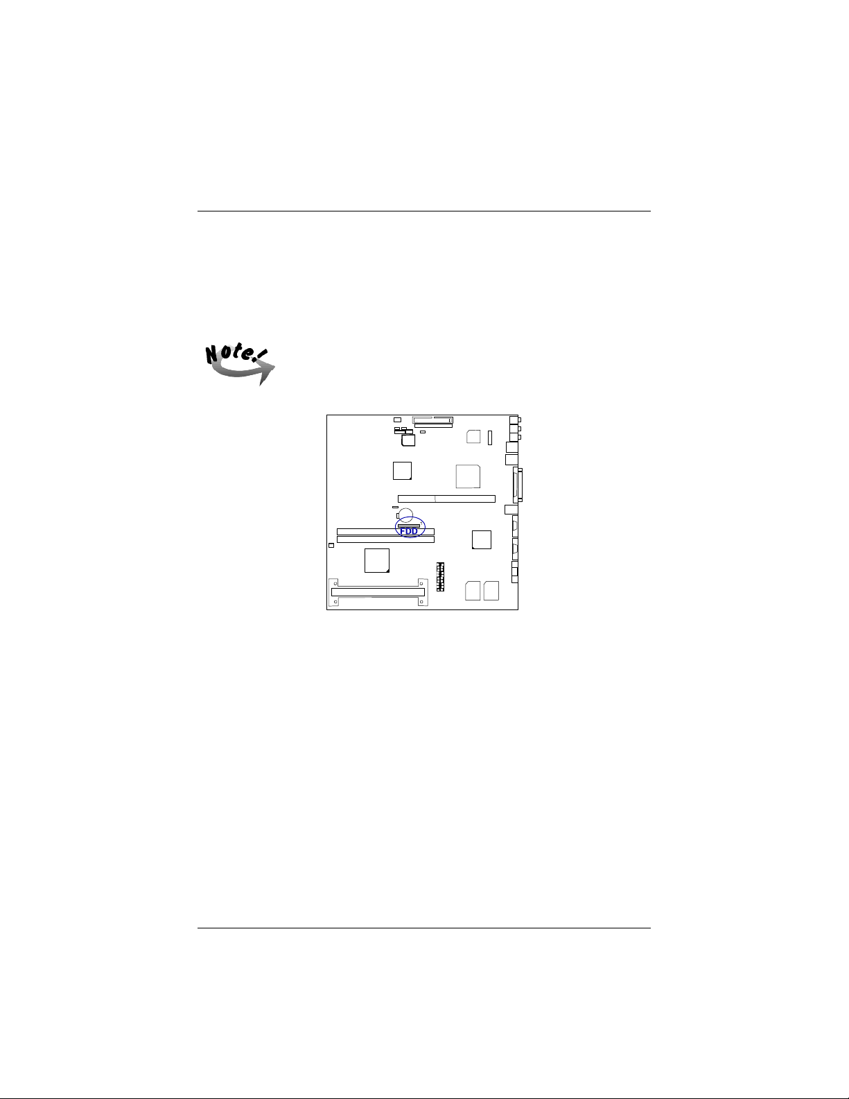
Mainboard Installation Procedures
Floppy Diskette Drive Connector: FDD
This 26–pin block connector connects to your slim floppy disk drive using the FFCcable that is provided with this mainboard. Insert one end of the silver-finger contact
and press down the FDD connector on both sides to lock it in place. After connecting
the single end to the mainboard, connect the other end to the floppy drive.
The FFC-cable should always be inserted with the side with the
exposed silver-finger in contact with the FDD connector pins.
85
 Loading...