

Page 1

PTM900
MAINBOARD
MANUAL
DOC No. : M0590040
: A0Rev.
: 12, 2006Date
Part No. : 25-13031-00
Page 2

PTM900 Mainboard Manual
1-2
This page is intended to be blank.
Page 3

PTM900 Mainboard Manual
Content
Overview........................................................................................ 1-3
The PTM900 Mainboard ............................................................ 1-3
Main Features............................................................................ 1-4
Installation Procedures .................................................................. 2-1
1.) Set System Jumpers ............................................................ 2-2
2). Install Memory Modules........................................................ 2-3
3). Install the CPU...................................................................... 2-3
Connect ATX Power............................................................... 2-5
4). Install Expansion Cards........................................................ 2-6
5). Connect Devices .................................................................. 2-7
Floppy Diskette Drive Connector ........................................... 2-7
IDE Device Connectors ......................................................... 2-8
Fan Connectors ..................................................................... 2-8
Power Connectors ................................................................. 2-9
Front Panel Block, Power LED, and Speaker Connector .... 2-10
CD _In Connectors ...............................................................2-11
Serial ATA Connectors ..........................................................2-11
Types of Rear Panel I/O Connectors ................................... 2-12
PS/2 Keyboard and Mouse Connector ................................ 2-12
RJ45 LAN Connector........................................................... 2-12
CRT Connector.................................................................... 2-13
Printer Connector................................................................. 2-13
Serial Port Connectors......................................................... 2-14
Page 4

PTM900 Mainboard Manual
1-2
Audio I/O Jacks.................................................................... 2-14
Front Audio Connector......................................................... 2-15
Universal Serial Bus Connectors ......................................... 2-15
This page is intended to be blank............................................ 2-17
BIOS Setup.................................................................................... 3-1
CMOS Setup Utility.................................................................... 3-1
Standard CMOS Setup .............................................................. 3-2
Advanced BIOS Features.......................................................... 3-4
Advanced Chipset Features ...................................................... 3-5
Integrated Peripherals ............................................................... 3-6
VIA OnChip IDE Device ......................................................... 3-6
VIA OnChip PCI Device ......................................................... 3-7
SuperIO Device ..................................................................... 3-8
USB Device Setting ............................................................... 3-9
Power Management Setup ..........................................................10
PC Health Status .........................................................................11
Frequency/Voltage Control ...................................................... 3-12
Load Optimized Defaults ......................................................... 3-13
Supervisor/User Password ...................................................... 3-13
Save and Exit Setup ................................................................ 3-13
Exit without Saving .................................................................. 3-13
Page 5
PTM900 Mainboard Manual
1-3
Chapter 1
Overview
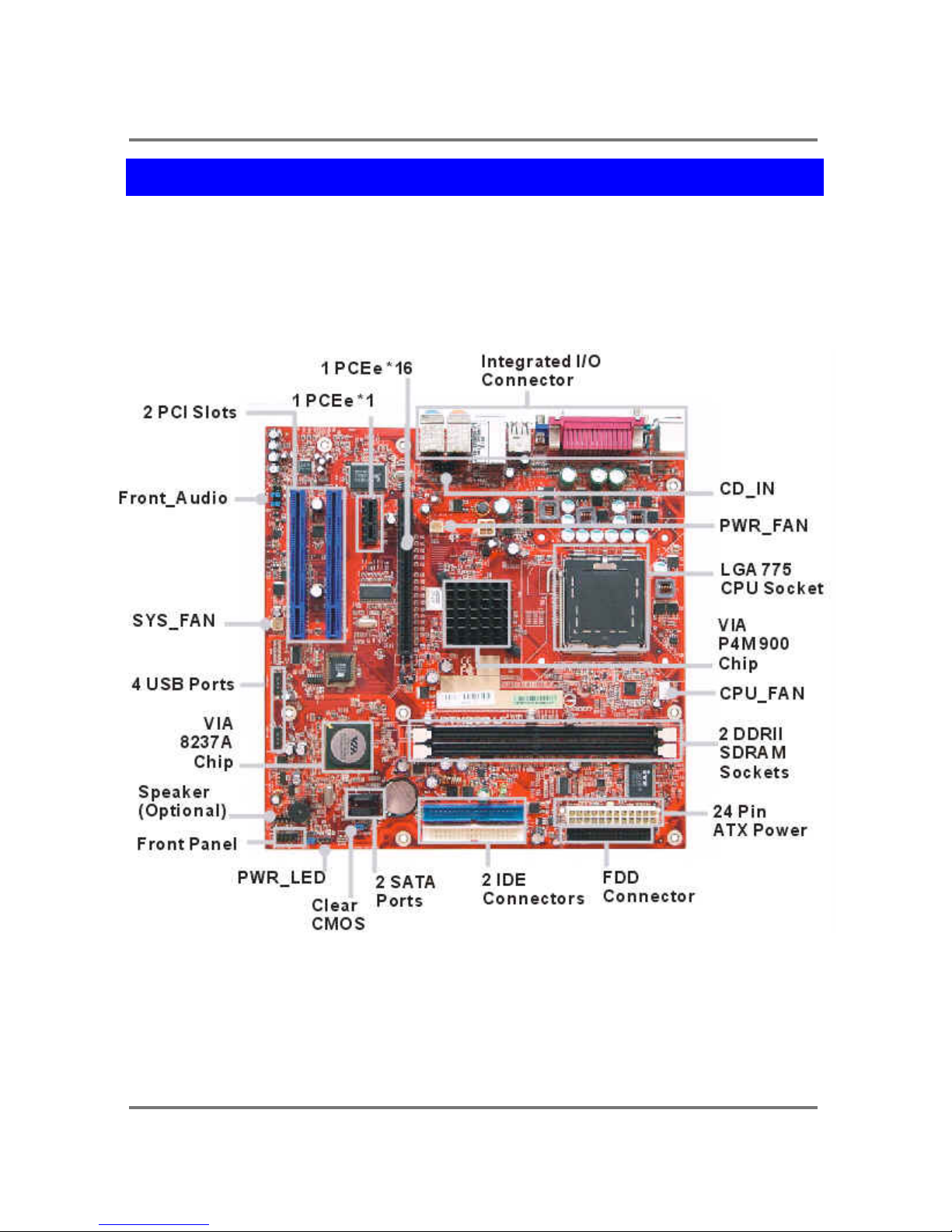
The PTM900 Mainboard
Page 6

PTM900 Mainboard Manual
1-4
Main Features
CPU
LGA 775 socket for Intel Celeron D/
Pentium4/ Pentium D/ Core 2 Duo Processor
compatible with Hyper-Threading Technology
FSB 533/800/1066 support.
Chipset
North Bridge: VIA® P4M900
South Bridge: VIA® VT8237A
Memory
2 Memory Sockets:
Support DDRII 400/533/667 MHz
total Memory Size up to 2 GBs
Expansion Slots
1 PCIe *16
1 PCIe *1
2 PCI Slots
IDE Connections
2 IDE Connectors - PIO Mode, Ultra DMA 66/100/133
Up to 4 Devices
SATA Connections
2x SATA with RAID0,1,JBOD
Audio Features
High Definition Audio:
2 Channels Realtek ALC 260 or
Page 7

PTM900 Mainboard Manual
1- 5
I/O Ports
1 x PS2 Mouse/Keyboard Connector
1 x COM port
1 x VGA port
1 x Parallel Port
4 x USB 1.1/2.0 ports
1 x RJ45
1 x Vertical Audio connectors : Mic-In, Line-In, Speaker-Out
1 x Vertical Audio connectors : Front L/R, Rear L/R, Center+Sub (8CH)
LAN
Realtek 8100C 10/100 Mbps Lan support or
Pin Hearders or Internal Connectors
2 x USB 2.0 pin-header (4 outputs)
1 x ATX Power connecotor (24pin)
1 x ATX 12V Power connecotor (4pin)
1 x Front Panel aoudio pin-header
1 x CD-in audio connecotor
1 x Power LED pin-header
1 x Speaker pin-header (Optional)
1 x Serial port pin-header (Optional)
1 x Chassis Intrusion pin-header (Optional)
Mounting Holes
6 holes
Mainboard Size
uATX -9.6 x 9.6 (unit: inch)
Page 8

PTM900 Mainboard Manual
1-6
This page is intended to be blank.
Page 9
PTM900 Mainboard Manual
2-1
Chapter 2
Installation Procedures
The mainboard has several user-adjustable jumpers that allow you to configure the
system to suit your requirements. This chapter contains information on the various
jumper settings on your mainboard.
To set up your computer, you must complete the following steps:
Step 1 - Set system jumpers.
Step 2 - Install memory modules.
Step 3 - Install the Central Processing Unit (CPU).
Step 4 - Install expansion cards.
Step 5 - Connect ribbon cables, cabinet wires and power supply.
Step 6 - Set up BIOS software.
Step 7 - Install supporting software tools.
WARNING: Excessive torque may damage the mainboard. When using
an electric screwdriver on the mainboard, make sure that the torque is
set to the allowable range of 5.0 ~ 8.0kg/cm.
Mainboard components contain very delicate Integrated Circuit (IC) chips.
To prevent static electricity from harming any of the sensitive components,
you should follow the following precautions whenever working on the
computer:
1. Unplug the computer when working on the inside.
2. Hold components by the edges and try not to touch the IC chips, leads or
circuitry.
3. Wear an anti-static wrist strap.
4. Place components on a grounded anti-static pad or on the bag
that came with the component whenever the components are
separated from the system.
Page 10
PTM900 Mainboard Manual
2-2
1.) Set System Jumpers
Jumpers are used to select the operation modes for your system. Some
jumpers on the board have three metal pins with each pin representing a
different function. A 1 is written besides pin 1 on jumpers with three pins. To
set a jumper, a black cap containing metal contacts is placed over the
jumper pin(s) according to the required configuration. A jumper is said to be
shorted when the black cap has been placed on one or two of its pins.
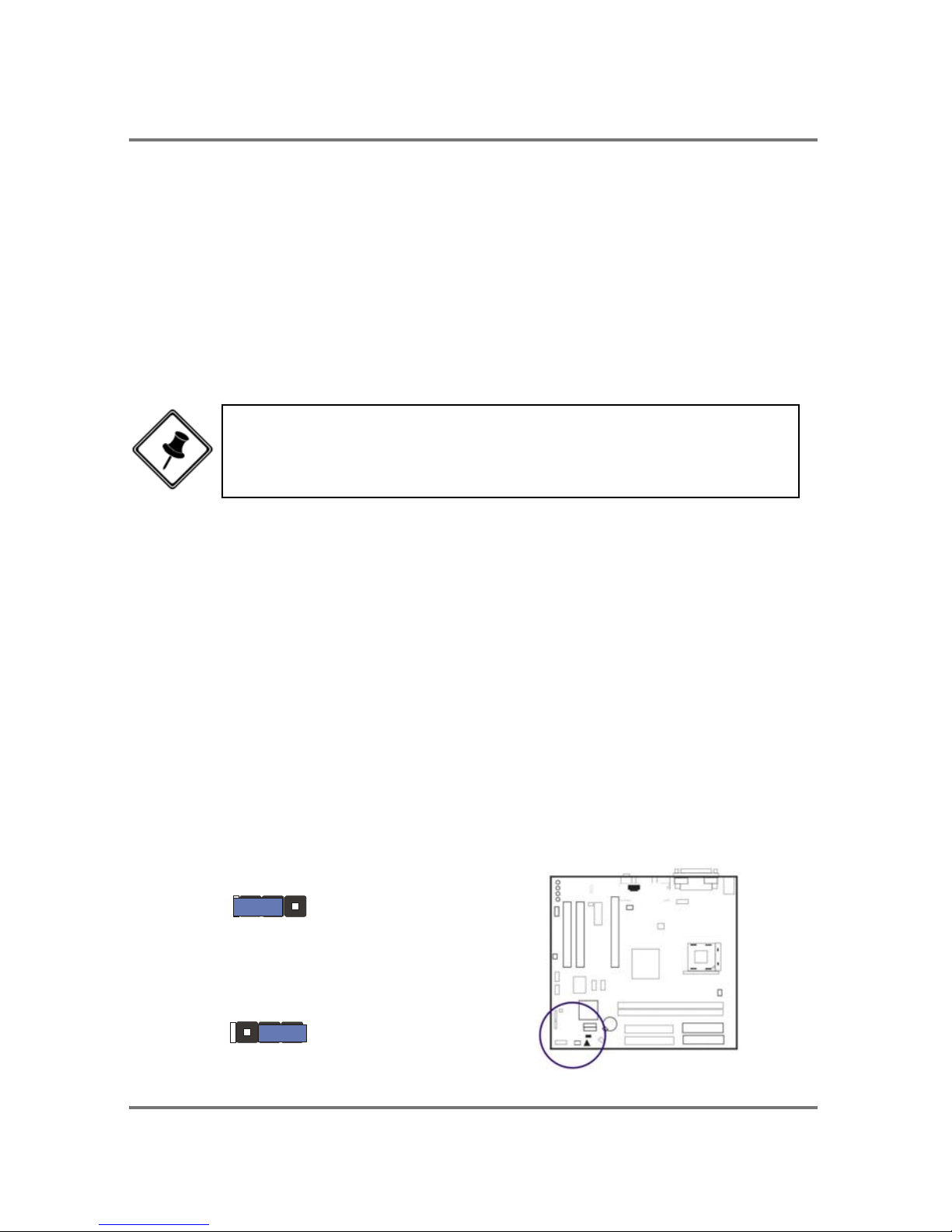
Clear CMOS
The CMOS RAM is powered by the onboard button cell battery.
To clear the RTC data:
(1) Turn off your computer;
(2) Open the system case and disconnect the ATX power cable;
(3) Place the jumper cap onto the pinpair 2-3 for at least 6 seconds
to enable CMOS clearance;
(4) Place the jumper cap onto the pinpair 1-2 to disable the effect of
CMOS clearance;
(5) Connect the ATX power cable and close the system case;
(6) Turn on your computer until CMOS checksum error appears;
(7) Hold down the Delete key as it boots;
(8) Enter the BIOS Setup to re-enter user preferences.
1 2 3
1 2
3
Normal
(Default)
Enable
(Clear CMOS)
NOTE: Users are not encouraged to change the jumper settings
that is not listed in this manual. Changing the jumper settings
improperly may adversely affect system performance.
Page 11
PTM900 Mainboard Manual
2- 3
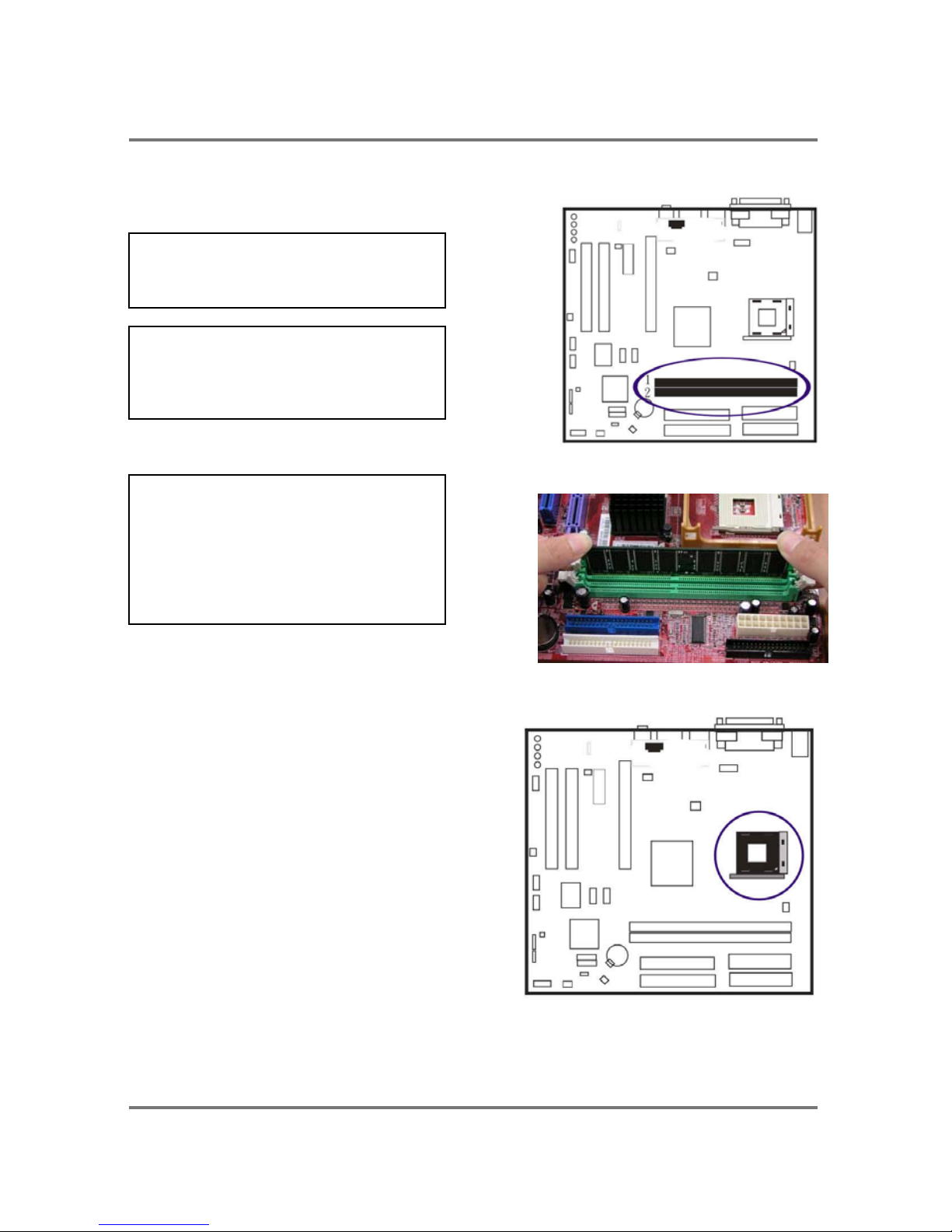
2). Install Memory Modules
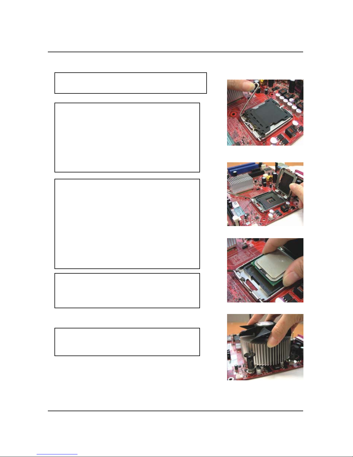
3). Install the CPU
The mainboard has built-in Switching Voltage
Regulator to support CPU Vcore
auto-detection. That is, It has the ability to
detect and recognize the CPU voltage, clock,
ratio and enables users to set up the CPU
frequency from the BIOS Setup Screen.
Users can adjust the frequency through
Frequency/Voltage Control of the BIOS
Setup Screen.
The procedures below show you how to
install your CPU and its fan and heatsink. First of all, locate the CPU socket on this
mainboard.
2. Install DDRII DIMM straight
down into the socket 1 using both
hands, then socket 2.
1. Locate DDRII DIMM sockets on
the mainboard.
3. The clip on both ends of the
socket will close up to hold the
DDRII DIMM in place when the
DDRII DIMM reaches the socket
bottom.
Page 12
PTM900 Mainboard Manual
2-4
Affix the CPU by pressing the lever
downward and locking it beside the socket.
Apply some thermal materials, such as
paste or tape, on the CPU top; and install a
fan with heatsink that approved by CPU
manufacturer to avoid CPU damage. For
detail information, please refer to the CPU
manufacturer website.
3. Place the fan with heatsink on the CPU
top and press down two plastic clips to hook
up with the holes on the retention module
1. Swing the lever upward to 90 degree.
2. Install the CPU and make sure the pin 1
orientation by aligning the socket corner
marking with the socket corner closest to
the lever tip.
Do not insert the CPU by force. Make sure
the processor is fully inserted into the
k
n
ll
i
.
4. Press down the white bar on each clip to
fasten the fan set on the retention module.
Page 13
PTM900 Mainboard Manual
2- 5
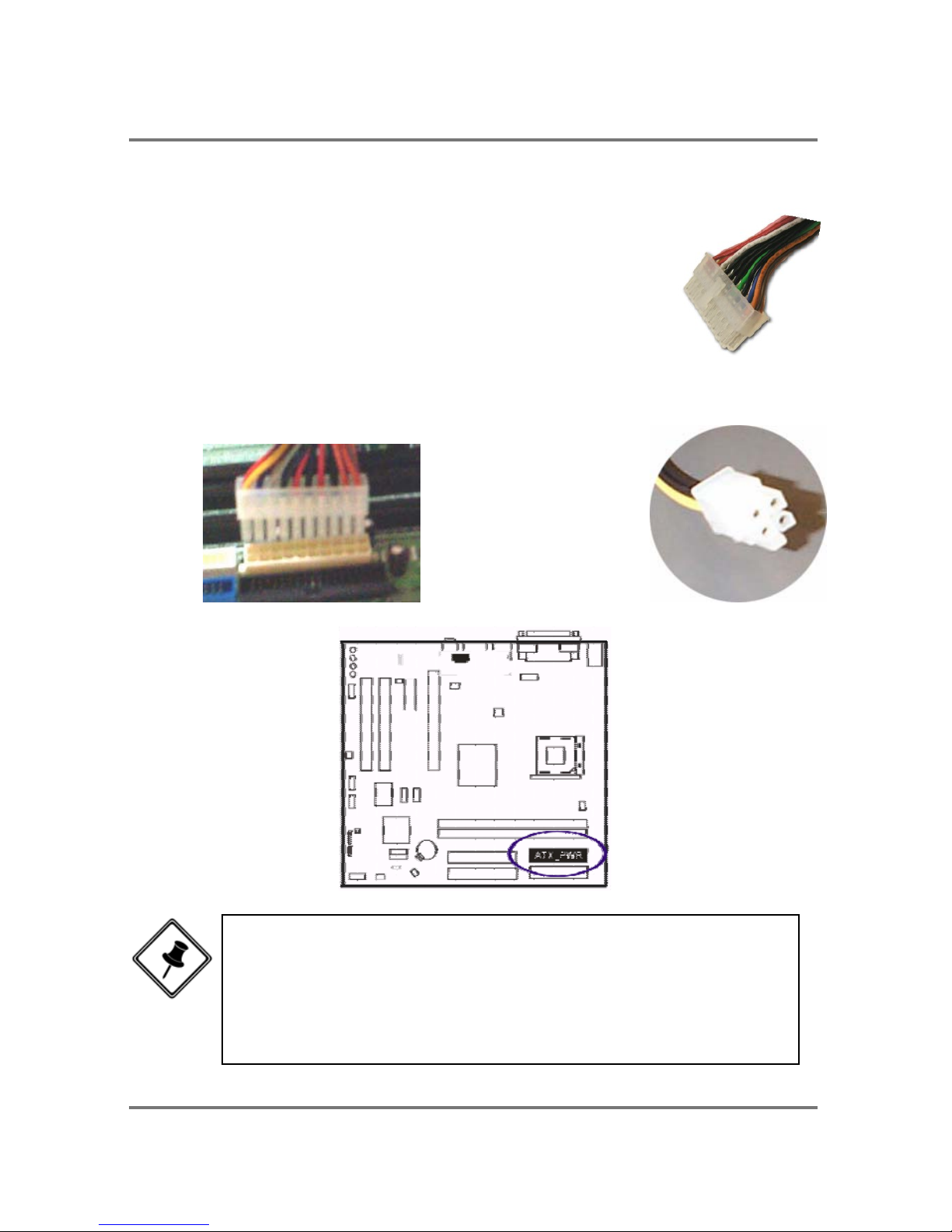
Connect ATX Power
The 24-hole power plug (top right) is connected to the ATX
power 24-pin pinheaders. The 4-hole 12V power plug (bottom
right) is inserted in the ATX_12V power connector.
The plug from the power supply will only insert in one
orientation because of the different hole sizes. Find the proper
orientation and push down firmly making sure that the pins are
aligned.
NOTE:
1. Insert the CPU (with fansink and retention module) on |socket.
2. Connect the 4-pin plug of the power supply
3. Connect the 24-pin plug of the power supply.
To remove the processor, please do it in reverse order.
Page 14

Page 15
PTM900 Mainboard Manual
2- 7
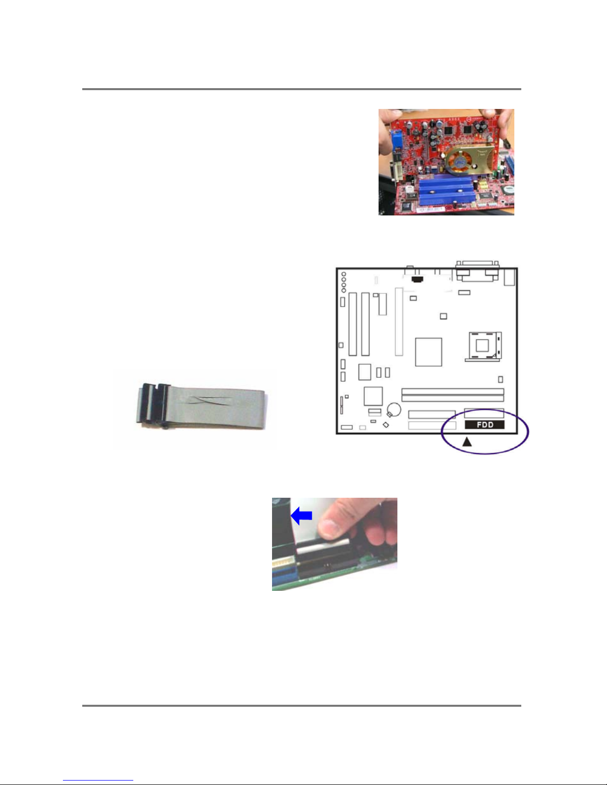
3. Push the card firmly into the slot. Push down on
one end of the expansion card, then the other.
Use this rocking motion until the card is firmly
seated inside the expansion slot. Secure the
card with the screw that was removed in Step2.
5). Connect Devices
Floppy Diskette Drive Connector
This connector provides the connection with
your floppy disk drive.
Insert the floppy ribbon cable (below) onto
the floppy connector.
The colored stripe (indicated by the arrow head, right) of the ribbon cable must be
the same side with the Pin 1.
Page 16
PTM900 Mainboard Manual
2-8
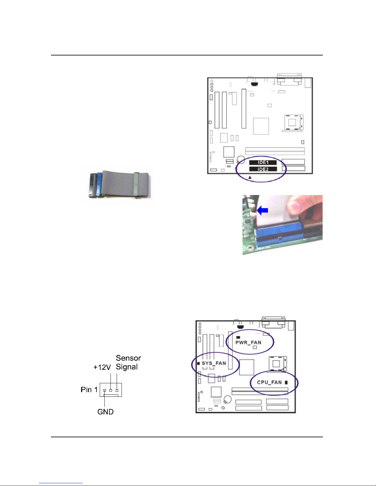
IDE Device Connectors
The two connectors, IDE1 (PRIMARY)
and IDE2 (SECONDARY), are used for
your IDE hard disk drives, CD drives,
LS-120|drives, or IDE ZIP drives.
Insert the IDE ribbon cable (below) onto the
IDE connector.
The colored stripe (indicated by the arrow head, right) of
the ribbon cable must be the same side as Pin 1.
Fan Connectors
The two connectors, CPU_FAN and SYS_FAN are linked to the CPU fan and case
fan, respectively. PWR_FAN can be used with the power supply cooling fan. Pin1
is GND, Pin2 is +12V, Pin3 is Signal (PWR_FAN Pin3 is no use).
Page 17
PTM900 Mainboard Manual
2- 9
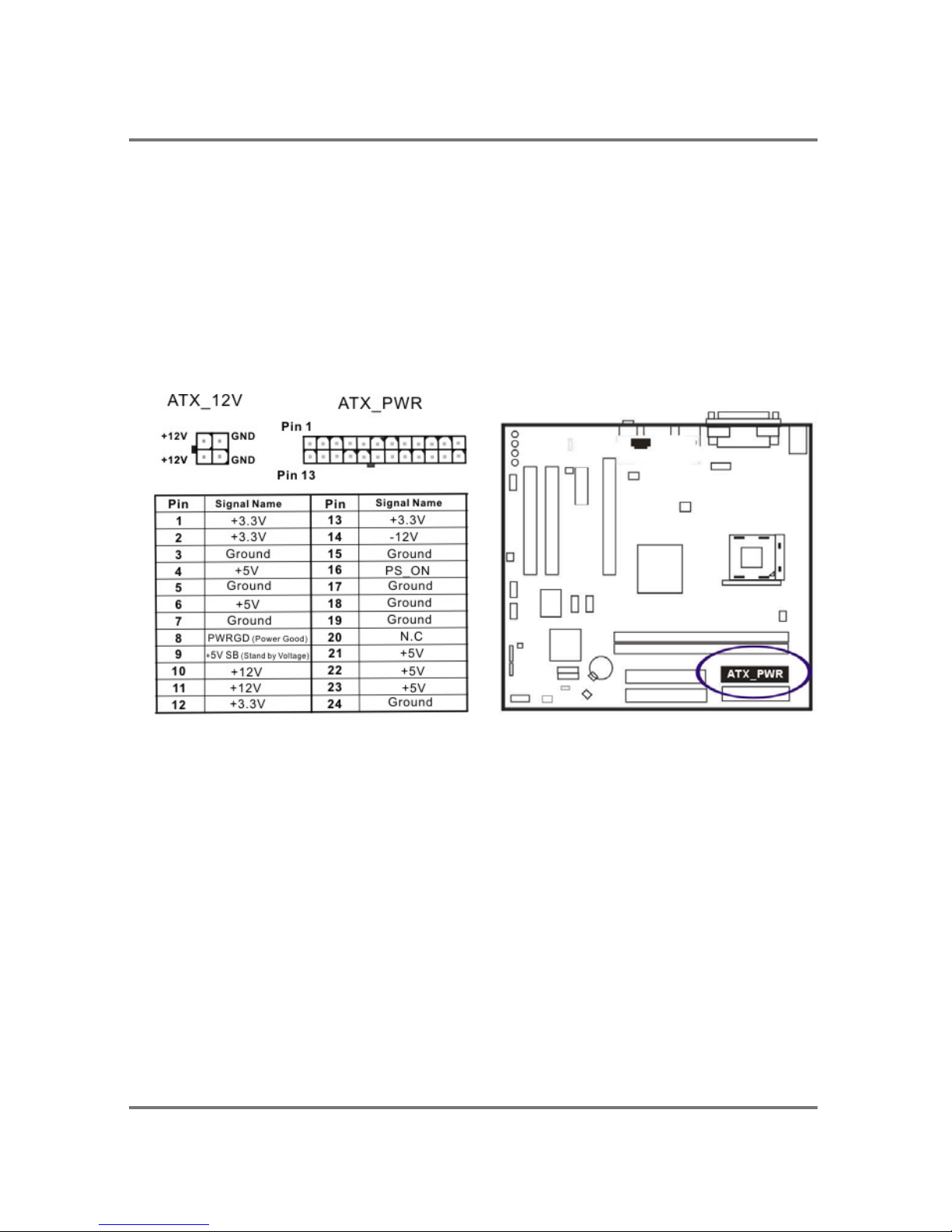
Power Connectors
The 20-pin male block connector is connected to the ATX power supply. The 4-pin
male block connector is for the ATX_12V power use. Both connectors are linked with
your ATX power supply. The plug from the power supply can only be inserted in one
orientation because of the different hole sizes. Find the proper orientation and push
down firmly making sure that the pins are aligned.
24
Page 18
PTM900 Mainboard Manual
2-10
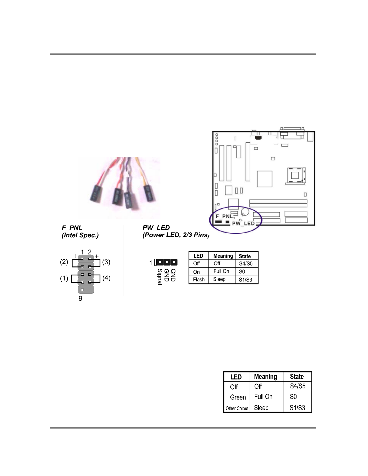
Front Panel Block, Power LED, and Speaker Connector
This block connector includes the connectors for linking with Power LED (3-pin),
HDD LED, power button, power/sleep/message waiting button, and the reset button
on the front panel of the system case. Please identify the polarities of the plug wires
for the case speaker and LEDs.
The plug wires (below) polarities of these
buttons will not affect the function.
(1) Reset Switch is connected to the reset button. Push this switch to reboot the
system instead of turning the power button off and on.
(2) HDD LED is connected to the IDE device indicator. This LED will blink when the
hard disk drives are activated.
(3) Power (Single and Dual) /Sleep LED
Please refer to the tables below for the
representations of LED states.
There is another 3-Pin Power LED connector on
board for some cases that have a 3-pin plug.
Page 19
PTM900 Mainboard Manual
2- 11
(4) Power Button is connected with the power button. Pushing this switch allows the
system to be turned on and off rather than using the power supply button.
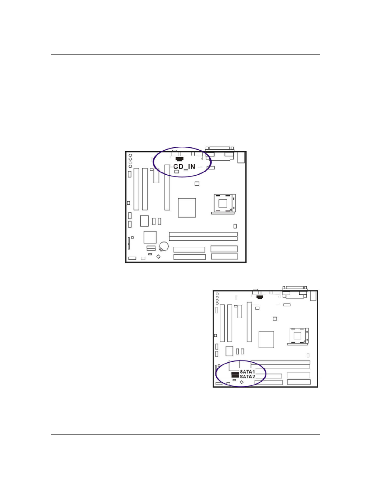
CD _In Connectors
The CD_IN connector is for CD-ROM drive audio analog input use. The pin
assignment are: Pin 1 is Left, Pin2 and 3 are GND, Pin 4 is Right.
Serial ATA Connectors
The 2 SATA connectors provide you with the
connections to serial ATA devices that confirm
to the Serial ATA specification. Serial ATA
supports all ATA and ATAPI devices. The
figures below left are two SATA cables (the top
one is for power; the next one is for data). The
data cable pin assignments of SATA connector.
Page 20
PTM900 Mainboard Manual
2-12
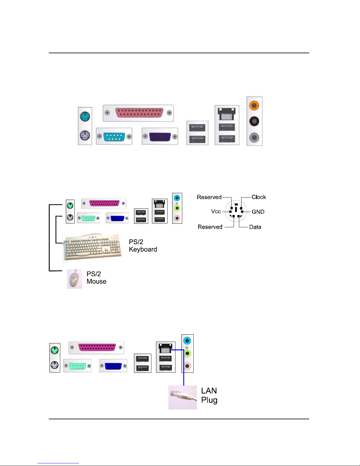
Types of Rear Panel I/O Connectors
The rear panel I/O connectors.
PS/2 Keyboard and Mouse Connector
These two 6-pin female connectors (keyboard is purple and mouse is green) are
used for your PS/2 keyboard and PS/2 mouse.
RJ45 LAN Connector
The RJ45 jack of the LAN port is used for the LAN cable plug.
Page 21
PTM900 Mainboard Manual
2- 13
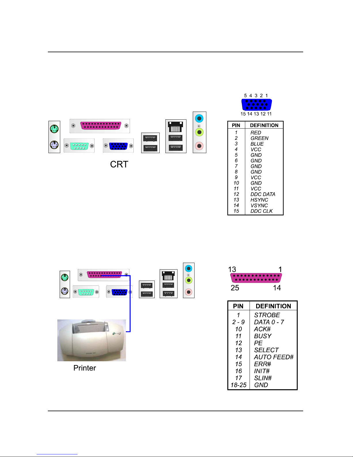
CRT Connector
This connector is linked to your monitor. The pinheaders pin assignments are shown
at right side.
Printer Connector
This burgundy-colored 25-pin D-Sub female connector is attached to your printer.
Page 22
PTM900 Mainboard Manual
2-14
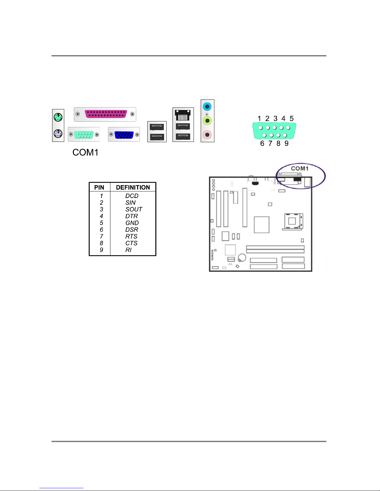
Serial Port Connectors
COM1 is teal colored 9-pin D-sub male connector, allowing you to connect with
devices that use serial ports, such as a serial mouse or an external modem.
Audio I/O Jacks
LINE_OUT (lime) can be connected to headphones or preferably powered speakers.
LINE_IN (light blue) allows tape players or other audio sources to be recorded by
your computer or played through the LINE_OUT.
MIC_IN (pink) allows microphones to be connected for audio input.
CES/Subwoofer (Orange) can be connected to the center/subwoofer speaker.
Rear (black) can be connected to the rear speaker.
Side (grey) can be connected to the side surrounding speakers.
Page 23
PTM900 Mainboard Manual
2- 15
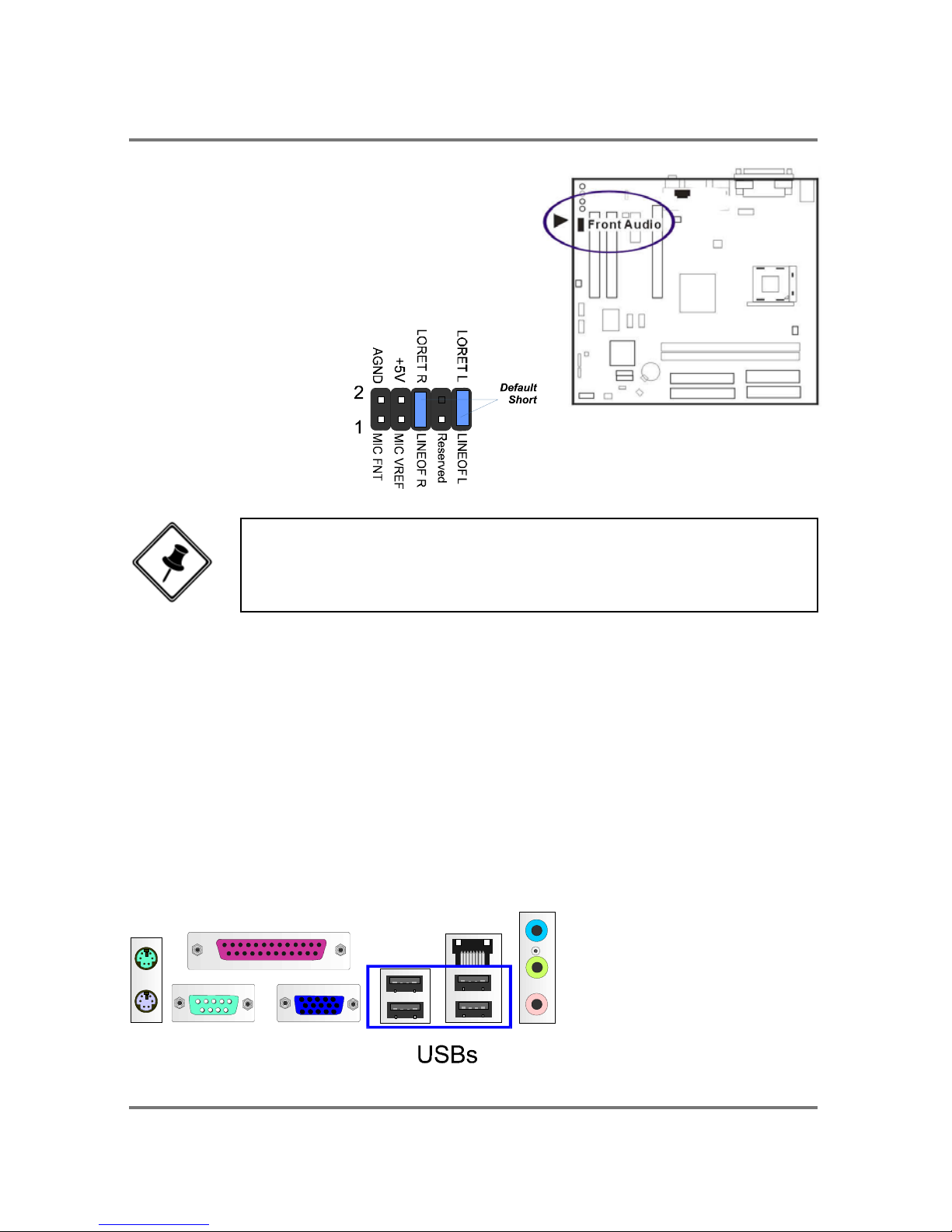
Front Audio Connector
The mainboard has a front panel
audio, F_AUDIO, connector
(Intel spec.). It allows you to
attach an audio device via the front
panel (instead of rear panel) by a
ribbon cable. Its pin
definitions
are presented below.
Universal Serial Bus Connectors
The mainboard has eight USB ports; four USB black jacks that are integrated on the
edge of the board, and four other USB ports (pinheaders) on the board. They allow
users to attach to USB devices either from the rear or front panels. Please note that
your operating system must support USB 1.1/2.0 features.
NOTE: If you do not use F_AUDIO, please keep the pinpair 5-6,
9-10 short as default; also, when the front headphone is plugged
in, the rear audio output will be disabled.
Page 24
PTM900 Mainboard Manual
2-16
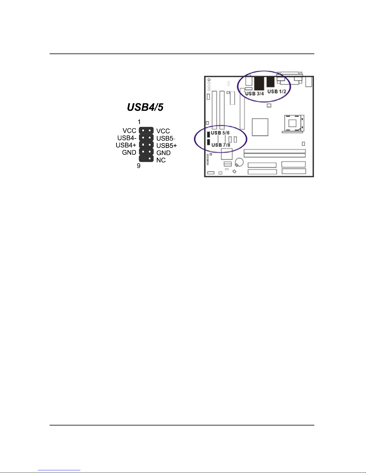
The figure at right shows the pin
assignments of the USB5/6. Those of
USB7/8 are similar.
Page 25

PTM900 Mainboard Manual
2- 17
This page is intended to be blank.
Page 26

Page 27
PTM900 Mainboard Manual
3-1
Chapter 3
BIOS Setup
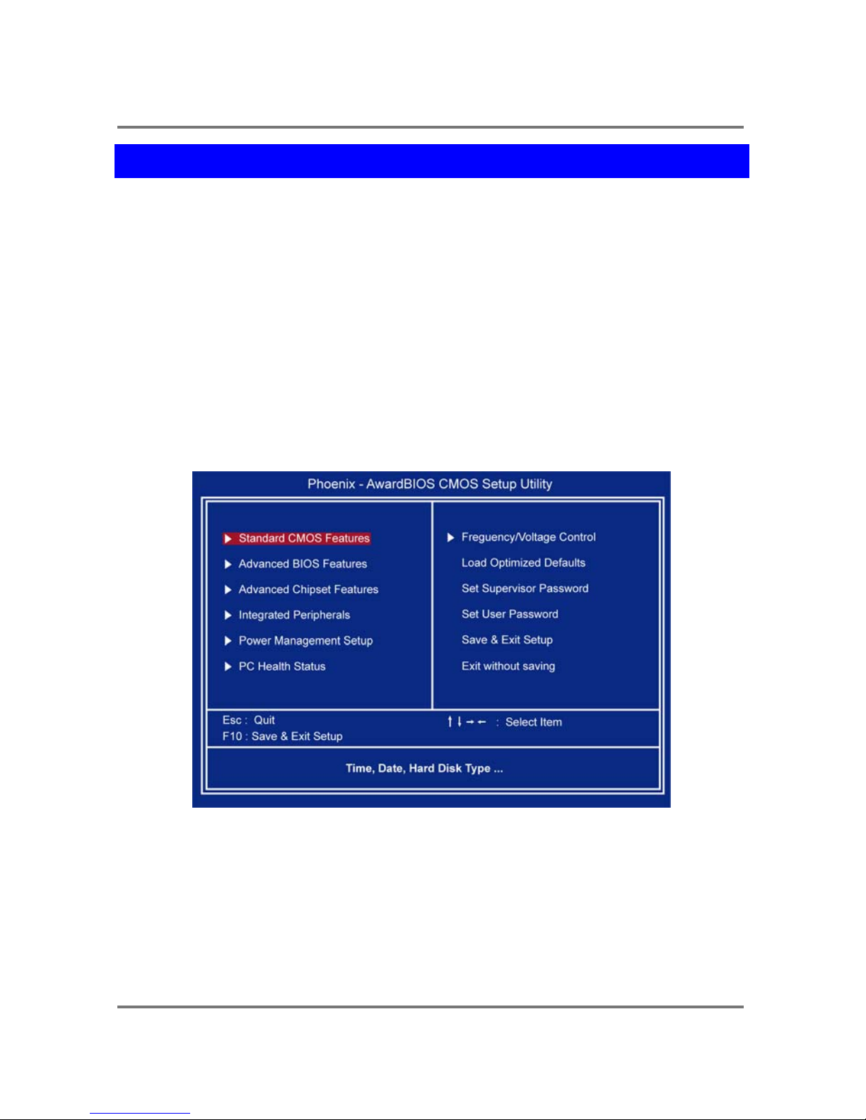
The mainboard comes with the chip that Award BIOS that contains the ROM Setup
information of your system. (This chip serves as an interface between the processor
and the rest of the mainboard components.) This section explains the information
contained in the Setup program and tells you how to modify the settings according to
your system configuration.
CMOS Setup Utility
The Setup utility program allows updates to the mainboard configuration settings.
The BIOS setup values will be saved in the CMOS. It is executed when the user
changes system configuration; user changes system backup battery; or the system
detects a configuration error and asks the user to run the Setup program. Use the
arrow keys to select and press Enter to run the selected program.
Page 28
PTM900 Mainboard Manual
3-2
Standard CMOS Setup
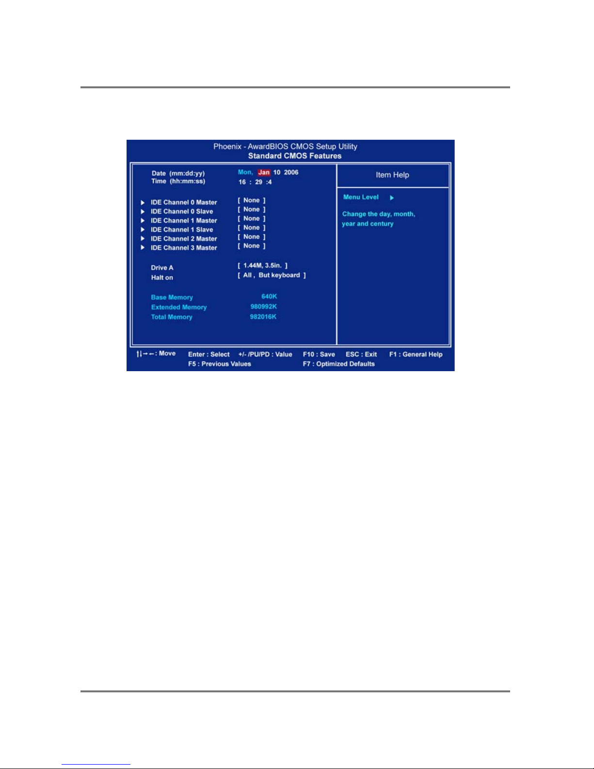
The Standard CMOS Setup screen is displayed above. Each item may have one or
more option settings. The system BIOS automatically detects memory size, thus no
changes are necessary. Use the arrow keys to highlight the item and then use PgUp
or PgDn keys to select the value you want in each item.
Date
To set the date, highlight the Date field and then press Page Up/Page Down or +/keys to set the current date. Follow the month, day and year format.
Time
To set the time, highlight the Time field and then press Page Up/Page Down or +/keys to set the current time. Follow the hour, minute, and second format.
Hard Disks
This field records the specifications for all non-SCSI hard drives installed in the
system. The onboard PCI IDE connectors provide Primary and Secondary channels
for connecting up to four IDE hard disks or other IDE devices. Each channel can
Page 29

PTM900 Mainboard Manual
3- 3
support up to two hard disks, the first of which is the Master and the second is the
Slave.
Hard Disk Configurations
Capacity: The hard disk size. The unit is Bytes.
Cylinder: The cylinder number of the hard disk.
Head: The read/write head number at the hard disk.
Precomp: The cylinder number of which the disk drive changes the write
current.
Landing Zone: The cylinder number on which the disk drive heads (read/write)
are seated when the disk drive is parked.
Sector: The sector number of each track defined on the hard disk.
Drive A
This field records the types of floppy drives installed in the system. To enter the
configuration value for a particular drive, highlight its corresponding field and then
select the drive type using the left- or right-arrow key.
Halt On
This field determines which types of errors will cause the system to halt.
Page 30
PTM900 Mainboard Manual
3-4
Advanced BIOS Features
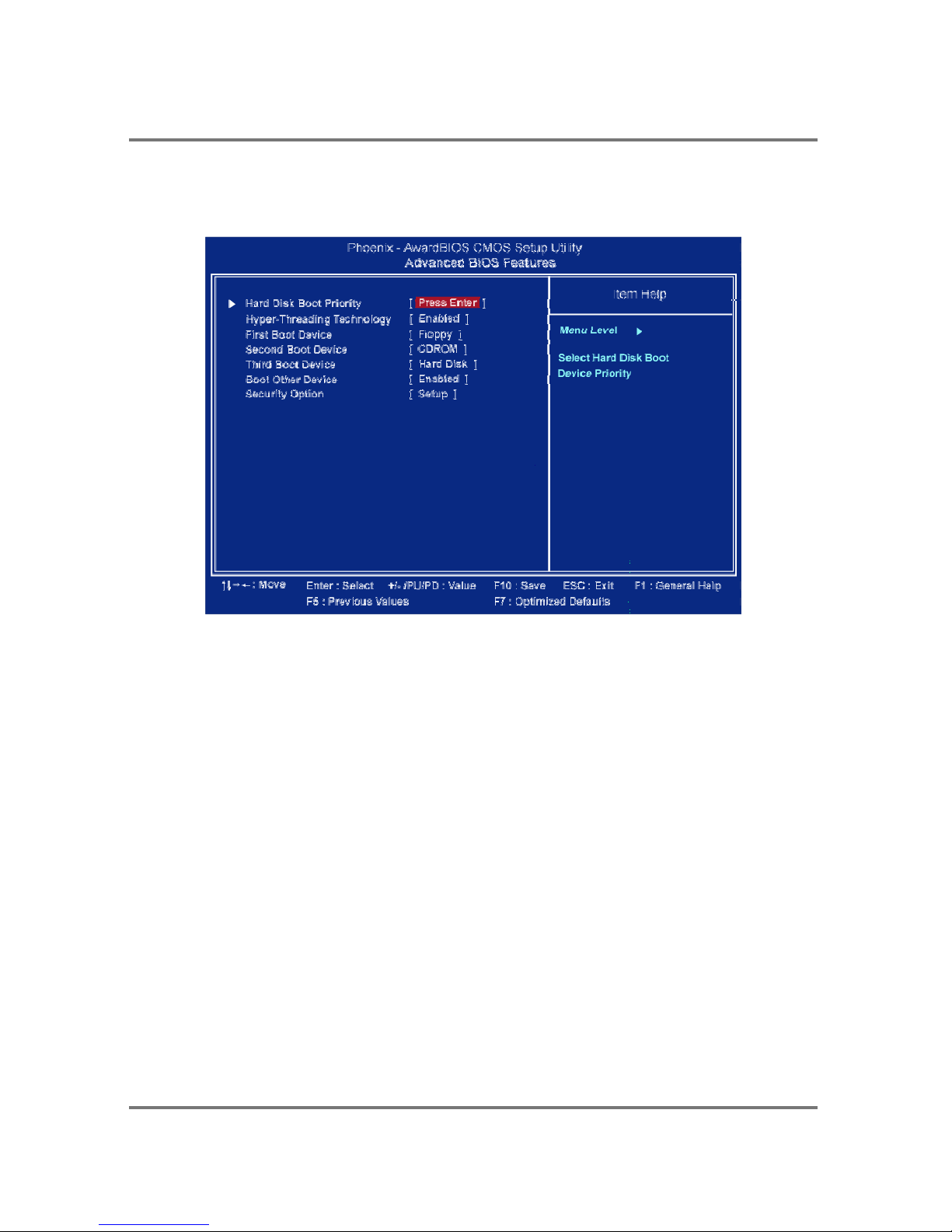
Hard Disk Boot Priority
This feature will auto detect all hard disks of bootable device on the system. It
also allows users to select hard disk device booting priority.
Hyper-Threading Technology
This feature allows user to enable or disable the Hyper-Threading Technology.
The options are: Enabled, Disabled.
First/Second/Third Boot Device
This feature allows user to select the boot device priority. The options are: Floppy,
LS120, Hard Disk, CDROM, ZIP100, USB-FDD, USB-ZIP, USB-CDROM, LAN,
Disabled.
Boot Other Device
This feature allows user to select the boot device priority.
The options are: Enabled, Disabled.
Page 31
PTM900 Mainboard Manual
3- 5
Security Option
Allows to set the security level of the system.The options: Setup, System.
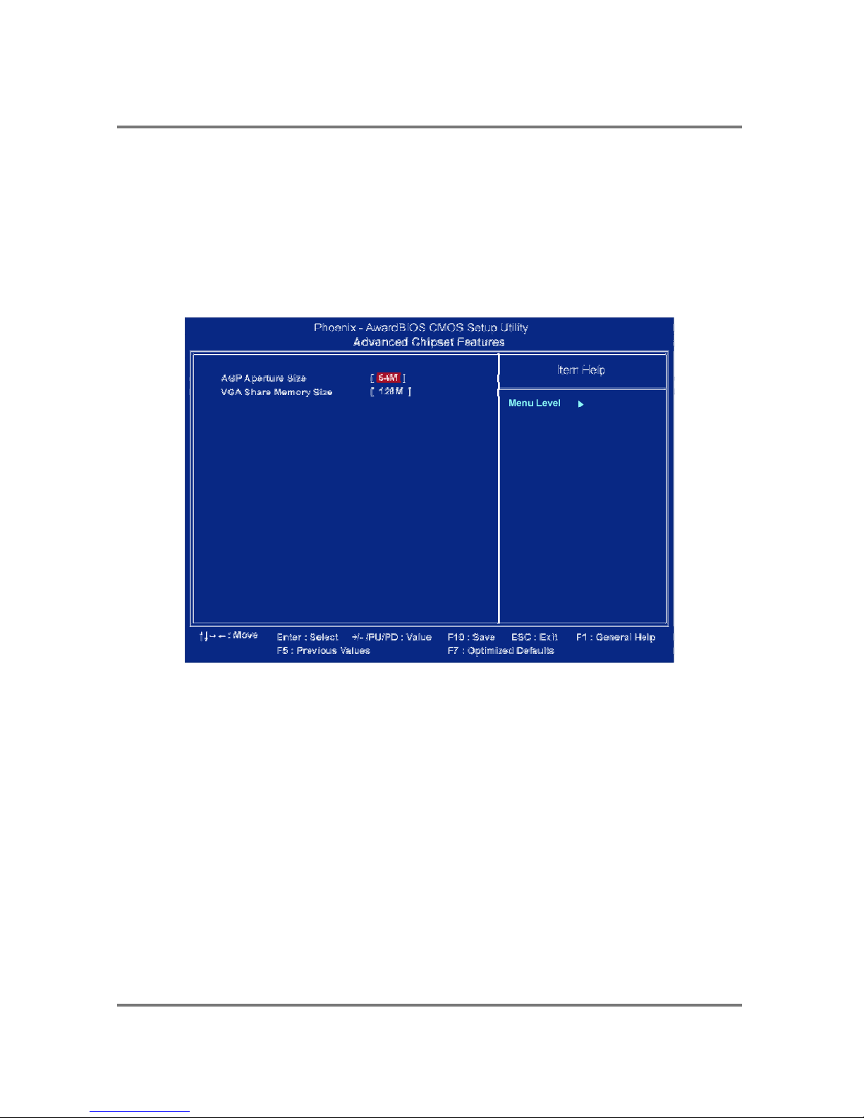
Advanced Chipset Features
AGP Aperture Size
It allows you to select the main memory frame size for AGP use.
The options list presents all provided possibilities.
VGA Share Memory Size
This feature allows you to select the size in the VGA shared memory.
The options are: 32M, 64M, 128M.
Page 32
PTM900 Mainboard Manual
3-6
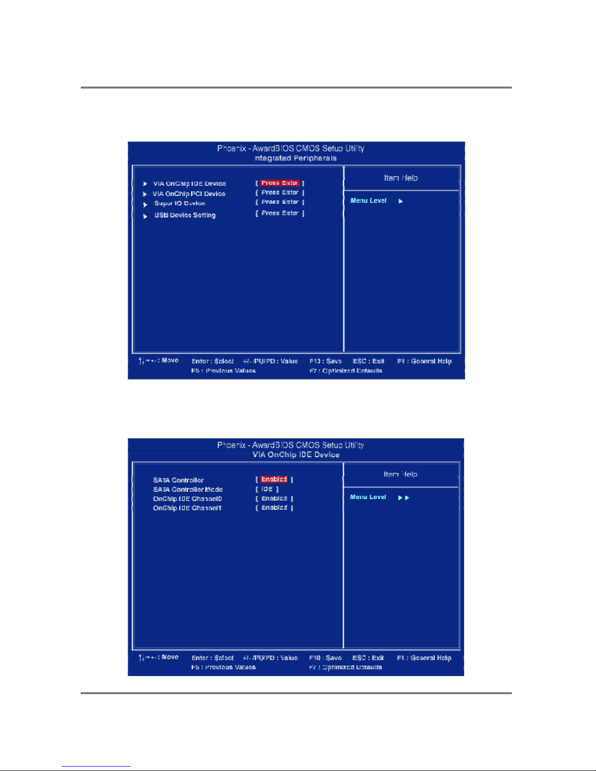
Integrated Peripherals
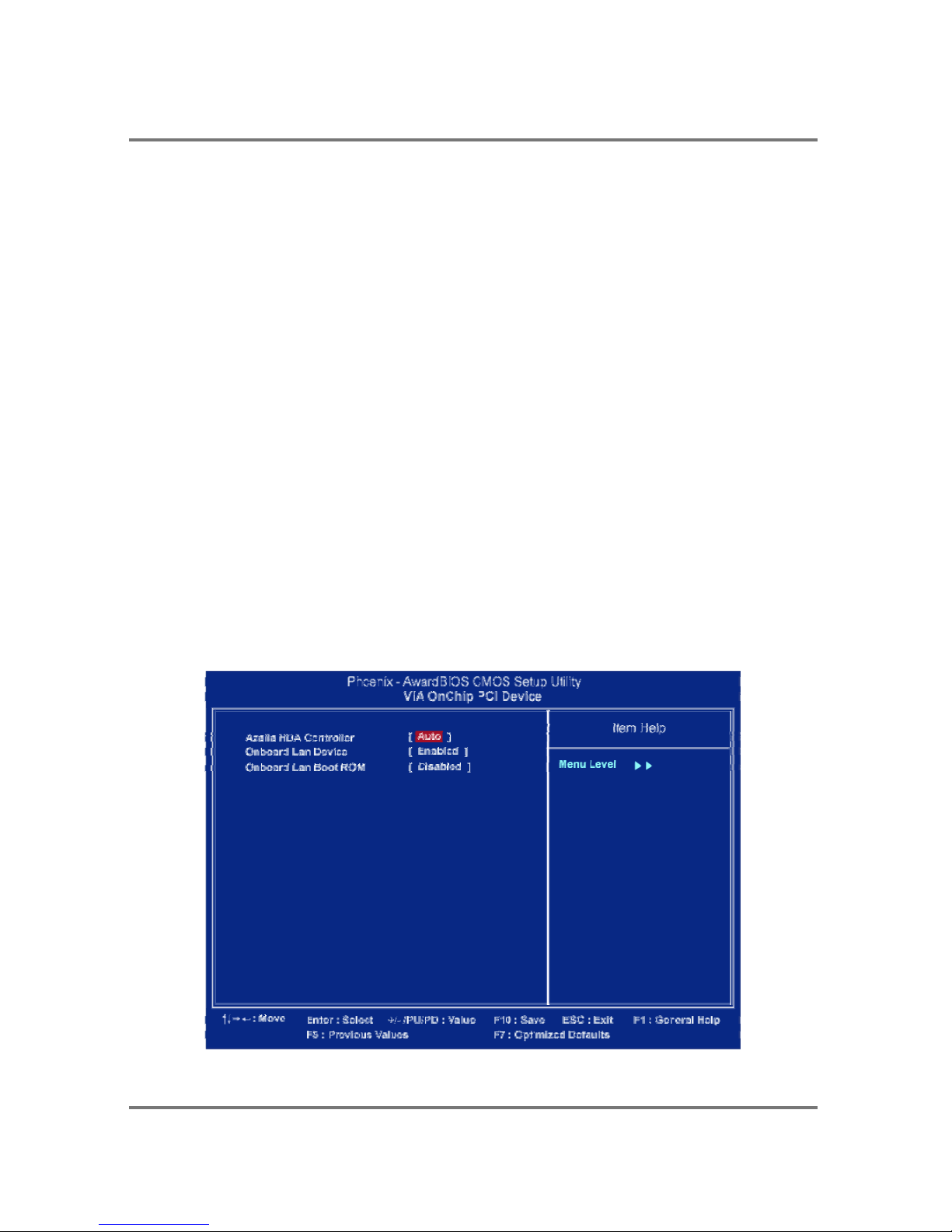
VIA OnChip IDE Device
Page 33
PTM900 Mainboard Manual
3- 7
SATA Controller
This item allows users to enable or disable the SATA controller function.
The options are: Enabled, Disabled.
SATA Controller Mode
This item allows users to select the SATA controller mode
The options are: IDE, Raid.
OnChip IDE Channel0
This item allows users to enable or disable the IDE Channel 0 function though the
system will auto detect this device.
The options are: Enabled, Disabled.
OnChip IDE Channel1
This item allows users to enable or disable the IDE Channel 1 function though the
system will auto detect this device.
The options are: Enabled, Disabled.
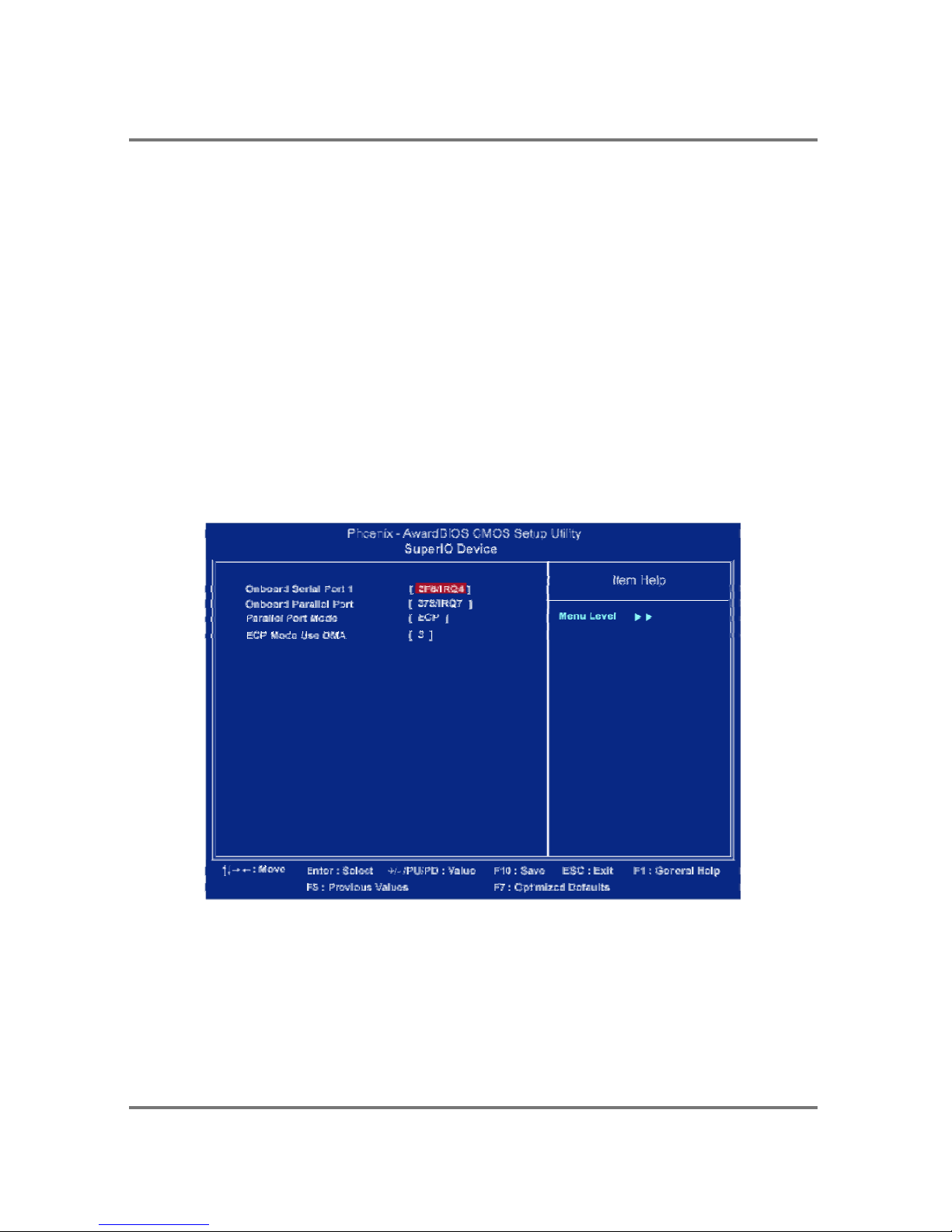
VIA OnChip PCI Device
Page 34
PTM900 Mainboard Manual
3-8
Azalia HAD Controller
It allows users to disable HD audio function in South Bridge.
The options are: Auto, Disabled.
Onboard LAN Device
This feature allows users to enable or disable the onboard LAN device.
The options are: Enabled, Disabled.
Onboard Lan Boot ROM
This feature allows users to enable or disable the onboard Lan boot ROM to boot
system. The options are: Enabled, Disabled.
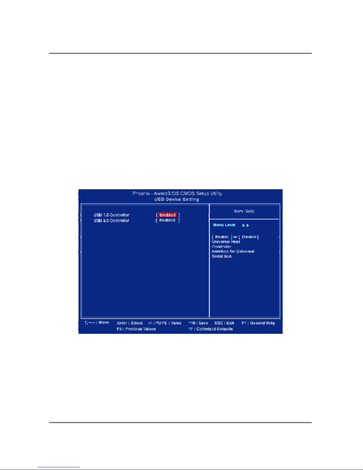
SuperIO Device
Onboard Serial Port 1
If the serial port 1 uses the onboard I/O controller, you can modify your serial port
parameters.
The options are: 3F8/IRQ4, 3E8/IRQ4, 2F8/IRQ3, 2E8/IRQ3, Disabled.
Page 35
PTM900 Mainboard Manual
3- 9
Onboard Parallel Port
Allows you to select from a given set of parameters if the parallel port uses the
onboard I/O controller.
Parallel Port Mode
Allows you to connect with an advanced printer via the port mode it supports. The
options are: SPP, EPP, ECP, ECP+EPP.
ECP Mode Use DMA
This feature allows you to select Direct Memory Access (DMA) channel if the ECP
mode selected. The options are: 1, 3.
USB Device Setting
USB1.0 Controller
Disable this option if you are not using the onboard USB 1.1 feature. The options
are: Disabled, Enabled.
USB2.0 Controller
Disable this option if you are not using the onboard USB 2.0 feature (USB 1.1 not
effected). The options are: Disabled, Enabled.
Page 36
PTM900 Mainboard Manual
3-10
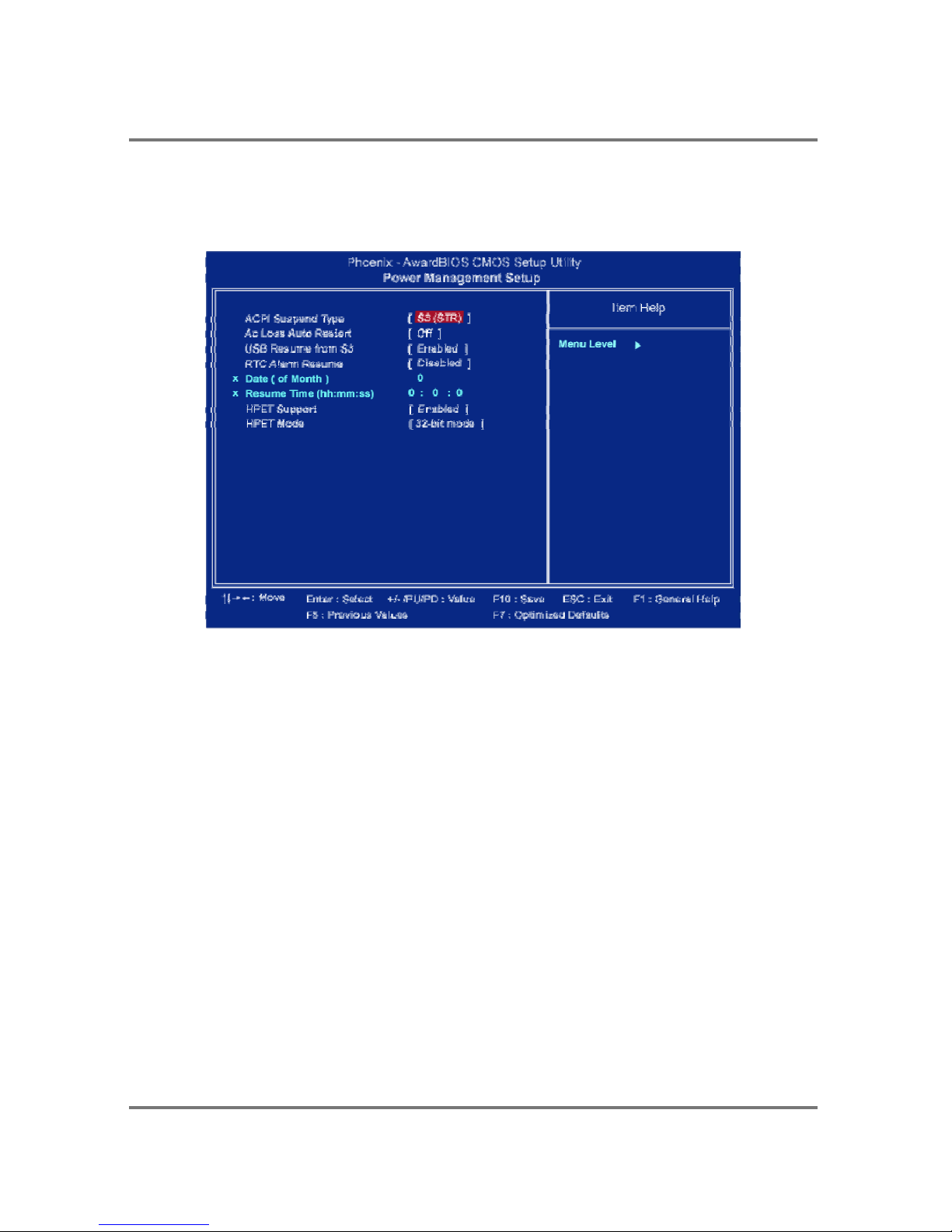
Power Management Setup
ACPI Suspend Type
This item allows you to select suspend mode when the system in ACPI mode.
The options are: S1 (POS), S3 (PTR), S1&S3.
AC Loss Auto Restart
When the system is shut down owing to the power failure, the system itself will
not be back to power on. This feature allows you to set the system back to the
previous power status when the system is resumed.
The options are Off, On, Former-STS.
USB Resume From S3
This option determines to activate or inactive the USB function when the system
resumes from S3.
RTC Alarm Resume
This option lets you set up the time to activate the system booting function
automatically.
Page 37
PTM900 Mainboard Manual
3- 11
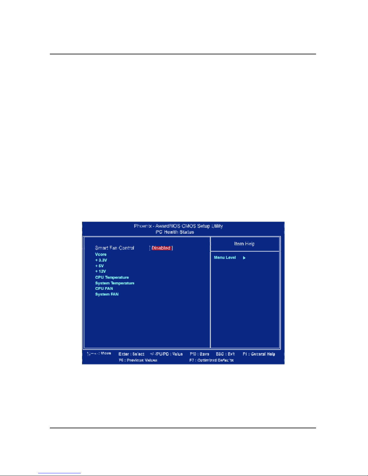
Date (of Month)
This option lets you set up the RTC alarm date.
Resume Time (hh:mm:ss)
This option lets you set up the RTC alarm time.
HPET Support
This option lets you enable or disable the “High Precision Event Timers” function.
The options are : Disabled, Enabled.
HPET Mode
This option lets you set up the “High Precision Event Timers” mode.
The options are : 32-bit, 64-bit.
PC Health Status
Vcore / 3.3V / +5V / +12V / CPU Temperature / System Temperature /
CPU FAN / System FAN
These items allow end users and technicians to monitor data provided by the
BIOS on this mainboard. It is not user-configurable.
Page 38
PTM900 Mainboard Manual
3-12
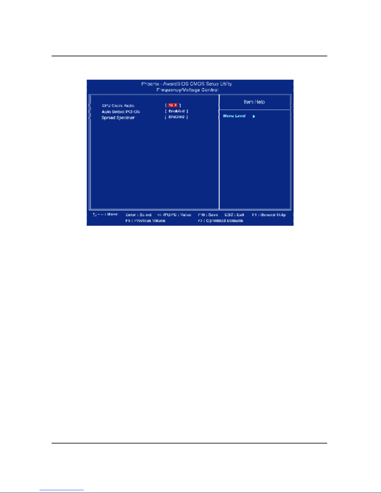
Frequency/Voltage Control
CPU Clock Ratio
This option lets you specify the Clock Ration for CPU frequency.
The options are : 15X, 16X, 17X. (depent on CPU type)
Spread Spectrum
This feature allows users to select the range of spread spectrum.
The options are: Disabled, -1.50%, -1.00%, -0.70%, -0.50%, +/-0.75%,
+/-0.50%, +/-0.35%, +/-0.25%.
Auto Detect PCI Clk
When enabled, BIOS will detect the PCI slot and DIMM slot. If no any device in,
BIOS will auto disable its clock. The options are: Enabled, Disabled.
Page 39

PTM900 Mainboard Manual
3- 13
Load Optimized Defaults
This submenu is selected for default settings which provide the best system
performance.
Supervisor/User Password
To enable the Supervisor/User passwords, select the item from the Standard
CMOS Setup. You will be prompted to create your own password. Type your
password up to eight characters and press Enter. You will be asked to confirm the
password. Type the password again and press Enter. To disable password, press
Enter twice when you are prompted to enter a password. A message appears,
confirming the password is disabled.
Under the BIOS Feature Setup, if Setup is selected under the Security Option
field and the Supervisor/User Password is enabled, you will be prompted
password every time you try to enter the CMOS Setup Utility. If System is
selected and the Supervisor/User Password is enabled, you will be requested to
enter the Password every time when you reboot the system or enter the CMOS
Setup utility.
Save and Exit Setup
After you have made changes under Setup, press Esc to return to the main menu.
Move cursor to Save and Exit Setup or press F10 and then press Y to change the
CMOS Setup. If you did not change anything, press Esc again or move cursor to
Exit Without Saving and press Y to retain the Setup settings. The following
message will appear at the center of the screen to allow you to save data to
CMOS and exit the setup utility: SAVE to CMOS and EXIT (Y/N)?
Exit without Saving
If you select this feature, the following message will appear at the center of the
screen to allow you to exit the setup utility without saving CMOS modifications:
Quit Without Saving (Y/N)?
Page 40

PTM900 Mainboard Manual
3-14
This page is intended to be blank.
 Loading...