

Page 1
Page 2

PT-2010
MAINBOARD
MANUAL
DOC No. : 15659
.
Rev.
:A0 2
Date
:
11,1996
Part No.
:
25-I
061
O-00
Page 3

Handling Precautions
Warning
:
I.
Static electricity may cause damage to the integrated circuits on the
mainboard.
Before handling any mainboard outside of its protective packaging,
ensure that there is no static electric charge in your body.
2. There is a danger of explosion if the battery is incorrectly replaced.
Replace only with the same or an equivalent type recommended by‘the
manufacturer
3. Discard used batteries according to the manufacturer’s instructions.
Observe the following basic precautions when handling the mainboard or other
computer components:
n
Wear a static wrist strap which fits around your wrist and is connected to a
natural earth ground.
n
Touch a grounded or anti-static surface or a metal fixture such as a water
pipe.
H
Avoid contacting the components on add-on cards, boards and modules and
with the “gold finger” connectors plugged into the expansion slot. It is best
to handle system components by their mounting bracket.
The above methods prevent static build-up and cause it to be discharged
properly.
Trademark
All trademarks mentioned in this manual are registered properly of the
respective owners.
Copyright
This manual may not, in whole or in part, be photocopied reproduced
transcribed, translated, or transmitted in whatsoever form without the written
the consent of the manufacturer, except for copies retained by the purchaser for
personal archival purposes.
Page 4
Chapter 1
Overview
Main Features
. . . . . . . . . . . . . . . . . . . . . . . . . . . . . . . . . . . . . . . . . . . . . . . . . . . . . . . . . . . . . . . . . . . . . . . . . . . . . . . . . . . . . . . . . . . . .
2
This User Manual
. . . . . . . . . . . . . . . . . . . . . . . . . . . . . . . . . . . . . . . . . . . . . . . . . . . . . . . . . . . . . . . . . . . . . . . . . . . . . . . . . . . . . . .
4
Something Interesting
. . . . . . . . . . . . . . . . . . . . . . . . . . . . . . . . . . . . . . . . . . . . . . . . . . . . . . . . . . . . . . . . . . . . . . . . . . . . . . . . .
5
The BIOS Setup Utility
. . . . . . . . . . . . . . . . . . . . . . . . . . . . . . . . . . . . . . . . . . . . . . . . . . . . . . . . . . . . . . . . . . . . .
5
IRQ Functionality
. . . . . . . . . . . . . . . . . . . . . . . . . . . . . . . . . . . . . . . . . . . . . . . . . . . . . . ..*....................
6
DMA Channels of ISA Cards
. . . . . . . . . . . . . . . . . . . . . . . . . . . . . . . . . . . . . . . . . . . . . . . . . . . . . . . . . . .
7
Enhanced IDE
. . . . . . . . . . . . . . . . . . . . . . . . . . . . . . . . . . . . . . . . . . . . . . . . . . . . . . . . . . . . . . . . . . . . . . . . . . . . . . . . . . .
7
Serial Infrared (SIR) Connections
. . . . . . . . . . . . . . . . . . . . . . . . . . . . . . . . . . . . . . . . . . . . . . . . . . . . .
.8
Highly Convenient Integrated I/O Connectors
. . . . . . . . . . . . . . . . . . . . . . . . . . . . . . . . . .
9
Chapter 2 Installation Procedures
Mainboard Layout
. . . . . . . . . . . . . . . . . . . . . . . . . . . . . . . . . . . . . . . . . . . . . . . . . . . . . . . . . . . . . . . . . . . . . . . . . . . . . . . . . . . . . .
12
1). Set System Jumpers
. . . . . . . . . . . . . . . . . . . . . . . . . . . . . . . . . . . . . . . . . . . . . . . . . . . . . . . . . . . . . . . . . . . . . . . . . . . . . . .
13
Jumpers
.
. . . . . . . . . . . . . . . . . . . . . . . . . . . . ..~..............................................................
Clear Password: CPW
. . . . . . . . . . . . . . . . . . . . . . . . . . . . . . . . . . . . . . . . . . . . . . . . . . . . . . . . . . . . . . .
Power Supply Select: VR3
. . . . . . . . . . . . . . . . . . . . . . . . . . . . . . . . . . . . . . . . . . . . . . . . . . . . . . . .
2). Install System RAM Modules
. . . . . . . . . . . . . . . . . . . . . . . . . . . . . . . . . ..*...........................
SDRAM Memory
. . . . . . . . . . . . . . . . . . . . . . . . . . . . . . . . . . . . . . . . . . . . . . . . . . . . . . . . . . . . . . . . . . . . . . . . . . . . . .
RAM Module Configuration
. . . . . . . . . . . . . . . . . . . . . . . . . . . . . ..*.........*.*...........*.*...
Install DIMMs
. . . . . . . . . . . . . . . . . . . . . . . . . . . . . . . . . . . . . . . . . . . . . . . . . . . . . . . . . . . . . . . . . . . . . . . . . . . . . . . . . . .
Remove DIMMs
. . . . . . . . . . . . . . . . . . . . . . . . . . . . . . . . . . . . . . . . . . . . . . . . . . . . . . . . . . . . . . . . . . . . . . . . . . . . . . .
Cache Memory
. . . . . . . . . . . . . . . . . . . . . . . . . . . . . . . . . . . . . . . . . . . . . . . . . . . . . . . . . . . . . . . . . . . . . . . . . . . . . . . . . .
Onboard Cache RAM
(256KB/5 12KB)
. . . . . . . . . . . . . . . . . . . . . . . . . . . . . . . . . . . . . . . . . . . .
Onboard Cache RAM and SRAM Module Mixture
(256KB/5 12KB)
. . . . . . . . . . . . . . . . . . . . . . . . . . . . . . . . . . . . . . . . . . . . . . . . . . . . . . . . . . . . . . . . . . . . . . . . . . . . . . . .
SRAM Module
(256KB/5 12KB)
. . . . . . . . . . . . . . . . . . . . . . . . . . . . . . . . . . . . . . . . . . . . . . . . . . . . . .
3). Install the CPU
. . . . . . . . . . . . . . . . . . . . . . . . . . . . . . . . . . . . . . . . . . . . . . . . . . . . . . . . . . . . . . . . . . . . . . . . . . . . . . . . . . . . . .
CPU External Clock (Bus) Frequency:
CLKl,
CLK2, and CLK3
. . . . . . . . . . . . . . . . . . . . . . . . . . . . . . . . . . . . . . . . . . . . . . . . . . . . . . . . . .
CPU to Bus Frequency Ratio:
FREQl and
FREQ2
. . . . . . . . . . . . . . . . . . . . . . . . . . . . . . . . . . . . . . . . . . . . . . . . . . . . . . . . . . . . . . . . . .
Intel Pentium
CPUs
. . . . . . . . . . . . . . . . . . . . . . . . . . . . . . . . . . . . . . . . . . . . . . . . . . . . . . . . . . . . . . . . . . .
Frequency
. . . . . . . . . . . . . . . . . . . . . . . . . . . . . . . . . . . . . . . . . . . . . . . . . . . . . . . . . . . . . . . . . . . . . . . . . . . . .
13
14
14
15
15
16
17
17
18
19
20
21
22
23
23
24
24
i
Page 5
PT-2010 Mainboard Manual
Voltage
.................................................................................
AMD-KS
CPUs
.........................................................................
Frequency
.............................................................................
Voltage
. . . . . . . . . . . . . . . . . . . . . . . . . . . . . . . . . . . . . . . . . . . . . . . . . . . . . . . . . . . . . . . . . . . . . . . . . . . . . . . . .
Cyrix 6x86
CPUs
. . . . . . . . . . . . . . . . . . . . . . . . . . . . . . . . . . . . . . . . . . . . . . . . . . . . . . . . . . . . . . . . . . . . . .
Frequency
.............................................................................
Voltage
.................................................................................
IBM 6x86
CPUs
........................................................................
Frequency
.............................................................................
Voltage
.................................................................................
Installation of Cyrix (or IBM) 6x86 CPU Fan
.........................
4). Install Expansion Cards .....................................
.
...................................
5). Connect Cables and Power Supply
.......................................................
Serial Port Connectors: COMl and COM2
...............................
CPU Fan Connectors: FAN
. . . . . . . . . . . . . . . . . . . . . . . . . . . . . . . . . . . . . . . . . . . . . . . . . . . . . . .
Floppy Diskette Drive Connector: FLOPPY
. . . . . . . . . . . . . . . . . . . . . . . . . . . . .
Block Connector: F
PNL
. . . . . . . . . . . . . . . . . . . . . . . . . . . . . . . . . . . . . . . . . . . . . . . . . . . . . . . . . .
-
Infrared Connector: IR
. . . . . . . . . . . . . . . . . . . . . . . . . . . . . . . . . . . . . . . . . . . . . . . . . . . . . . . . . . . . . .
PS/2 Keyboard Connector: PS2 KB
. . . . . . . . . . . . . . . . . . . . . . . . . . . . . . . . . . . . . . . . .
-
PS/2
Mouse Connector: PS2 MS
. . . . . . . . . . . . . . . . . . . . . . . . . . . . . . . . . . . . . . . . . . . . .
-
Power Connector: ATXPOWER
. . . . . . . . . . . . . . . . . . . . . . . . . . . . . . . . . . . . . . . . . . . . . . .
Standard Power Connector: POWER
. . . . . . . . . . . . . . . . . . . . . . . . . . . . . . . . . . . . . . . .
IDE HDD Device Connectors:
PRIMARY and SECONDARY
. . . . . . . . . . . . . . . . . . . . . . . . . . . . . . . . . . . . . . . . . . . . . . . . .
Printer Connector:
PRINTER
. . . . . . . . . . . . . . . . . . . . . . . . . . . . . . . . . . . . . . . . . . . . . . . . . . . .
Remote Power Supply Connector: RPW
CON . . . . . . . . . . . . . . . . . . . . . . . .
-
Universal Serial Bus Connectors
. . . . . . . . . . . . . . . . . . . . . . . . . . . . . . . . . . . . . . . . . . . . . . .
25
26
26
27
28
28
29
30
30
31
32
33
35
35
35
36
36
37
38
38
39
39
40
40
41
41
Chapter 3
Award BIOS Setup
CMOS Setup Utility
...................................................................................
43
Standard CMOS Setup
’
...............................................................................
44
BIOS Features Setup
..................................................................................
46
Chipset Features Setup
...............................................................................
49
Power Management Setup
..........................................................................
52
.
PNP/PCI Configuration Setup
....................................................................
55
Load BIOS Defaults
...................................................................................
56
ii
Page 6

Table of Contents
Integrated Peripherals.................................................................................
57
Supervisor/User Password ..........................................................................
60
IDE HDD Auto Detection ..........................................................................
61
Save and Exit Setup....................................................................................
62
Exit Without Saving ...................................................................................
62
. . .
III
Page 7
Overview
The
PT.20
10 mainboard combines the advanced capabilities of the Intel
82430VX
PCIset
with a high-performance concurrent
PC1
local bus architecture
to provide the ideal platform for unleashing the unsurpassed speed and power of
the Intel Pentium processor.
This highly-flexible mainboard is designed to run a full range of Intel Pentium,
Cyrix 6x86, IBM
6x86and
AMD-KS processors, and can be easily upgraded
using its 32 l-pin ZIF socket. The processor’s advanced performance is
complemented by a second level write back Pipeline Burst
SRAM
cache of up
to 5 12KB and main memory of up to 128MB DRAM. The main memory is
installed using the board’s two
16%pin
DIMM sockets that accept lightning-fast
SDRAMs.
The PT-20 10 integrates a full set of I/O features
onboard,
including two
1655OA
UART compatible serial ports, one
EPP/ECP
capable parallel port, and one
Floppy Disk Drive controller. The
IrDA
compliant serial port and
onboard
SIR
support further enhance system I/O
connectivityIt
also
bcomes
with a built in
Enhanced IDE controller that provides convenient, high-speed
PC1
Bus Master
connections with up to four IDE devices, including Hard Disk and CD-ROM
drives. Four
16,bit
ISA slots and four
32-bit PC1
slots provide ample room for
further expansion. The mainboard also features support for the state-of-the-art
Universal Serial Bus (USB) that provides ease-of-use and high-speed Plug
&
Play connections to future USB compliant peripheral devices.
This chapter gives you a brief overview of the PT-2010 mainboard. In addition
to basic information on the board’s main components and features, it also
provides advice on how to upgrade and expand it. For updated BIOS, drivers, or
product release information, please visit
FIG’s
home page at:
http:lfwww.fic.com.tw.
Congratulations on your decision to adopt the
PT.20
10 mainboard. With its
high-speed
PC1
local bus architecture and ultra-fast I/O connections, the
PT-
2010 provides the ultimate solution for optimizing the performance of your
high-end system.
1
Page 8
PT-2010 Mainboard Manual
Main Features
The PT-20 10 mainboard comes with the following high-performance features:
.
Easy Installation
Award BIOS with support for Plug and Play, auto detection of Hard Drive
and IDE features, and MS Windows 95 compatible.
Flexible Processor Support
The onboard 32 1 -pin ZIF socket supports Intel Pentium
(P54C)
CPU speed
75/90/100/120/133/150/166/200 MHz processors/
P54CTB / P55C
(optional by splitting the voltage regulator).
Cyrix 6x86-P120+ (100 MHz) / 6x86-P133+ (110 MHz) / 6x86-P150+
(120 MHz) / 6x86-P
166+
(133 MHz) processors.
IBM 6x86-P120+ (100 MHz) /
6x86-P133+
(110 MHz) /
6x860P150+
(120 MHz) / 6x86-P166+ (133 MHz) processors.
AMD KS-PR75 (75 MHz) / K5-PR90 (90 MHz) /
K5-PRlOO
(100 MHz) /
K5-PR120 (90 MHz) /
K5-PR133
(100 MHz) / K5-PR150 (120 MHz) /
KS-PR166 (133 MHz) processors.
Leading Edge Chipset
Intel 82430VX
chipset,
including a CPU interface controller, advanced
cache controller, integrated DRAM controller, synchronous ISA bus
controller,
PC1
local bus interface, integrated power management unit.
Ultra-fast Level II Cache
Supports onboard 256KB/5
12KB
synchronous PBSRAM direct-mapped
write-back cache memory.
,
Versatile Main Memory Support
Accepts up to 128MB RAM in two banks using two
168-pin
DIMMs of 8,
16,32,64MB
with support for SDRAM and
ED0
memory.
ISA &
PC1
Expansion Slots
Four
16-bit
ISA and four 32.bit
PC1
expansion slots provide all the room
you need to install a full range of add-on cards.
USB Support
Two Universal Serial Bus connectors integrated into rear I/O panel.
Enhanced
PC1
Bus Master IDE Controller
2
Page 9
Overview
Enhanced
PC1
Bus Master IDE Controller
Integrated Enhanced
PC1
local bus IDE controller with two connectors
supports up to four IDE devices such as Hard Disk, CD-ROM or Tape
Backup drives via two channels for high speed data throughput. This
controller
supports’PI0
Modes 3 and 4, and DMA Mode 2 for optimized
system performance.
Super Multi I/O
Integrated
Winbond W83877F
Plug and Play Super I/O
chipset
features two
16550A
UART compatible serial ports, one
EPP/ECP
capable
parallel port, one IR port, and one Floppy Disk Drive connector.
3
Page 10

PT-2010 Mainboard Manual
This User Manual
This manual is designed to guide you and facilitate your use of the PT-2010
mainboard. It contains a description of the design and features of the mainboard,
and also includes useful information for changing the configuration of the board
and the system it is installed in. The manual is divided into three chapters:
n Chapter 1
-
Overview
gives an overview of the mainboard and describes its major components
and features.
W
Chapter 2 - Installation Procedures
gives instructions on how to set up the mainboard, including jumper
settings and CPU installation guides.
n
Chapter 3 - Award BIOS Setup
briefly explains the mainboard’s BIOS system setup in general and tells you
how to run it and change the system configuration settings.
NOTE : The material in this manual is for information only and is subject to
change without notice. We reserve the right to make changes in the product
design without reservation and without notification to its users. We shall not
be liable for technical or editorial omissions made herein; nor for incidental or
consequential damages resulting from the furnishing, performance, or use of
this material.
.
4
.
Page 11

Overview
Something. Interesting
This section provides useful information that you will need to know should you
decide to modify or upgrade the configuration of the mainboard and the system
it is installed in. If you do not have the confidence to upgrade the mainboard
yourself, we advise that you consult a qualified service technician for assistance.
The BIOS Setup Utility
The BIOS (Basic Input Output System) is the basic firmware that instructs the
computer how to operate. For the BIOS to work properly, there must be a record
of the computer’s hardware and configuration settings for it to refer to. This
record is created using the Setup Utility, a program that is stored permanently in
the BIOS ROM chip on the mainboard.
.
The system configuration record created by the Setup Utility is also stored on
the mainboard, but not permanently. This section of the memory it is stored is in
the NVRAM.
-
When you buy your computer, the system configuration record will already be
set and may in some cases differ from the basic defaults. The first time you use
your computer or when you need to re-configure your system, you should run
the Setup Utility and write down the settings.
5
Page 12
PT-2010 Mainboard Manual
IRQ Functionality
As you read through this manual, you will see the term IRQ on a number of
occasions. It is important for you to know what this term means, particularly if
you intend to upgrade your system.
IRQ stands for Interrupt Request, the process in which an input or output device
tells the processor to temporarily interrupt its current task and immediately
process something from the source of the interrupt. When it has completed this,
the processor returns to the task it was already processing. Devices that need an
IRQ line to operate sometimes need to have exclusive use of that line.
A large number of add-on cards, such as sound cards and LAN cards, require
the use of an IRQ line to function. Some of
IRQs
may already be in use by
components in the system such as the keyboard and mouse. Add-on cards that
need to use an IRQ draw from the unused group of
IRQs.
When installing a card
that uses an IRQ, it will have a default IRQ setting which you might have to
change if that IRQ is already in use and cannot be shared.
Both ISA and
PC1
add-on cards may need to use
IRQs.
System
IRQs
are
available to add-on cards installed on the ISA bus first; the remaining ones can
be used by cards installed on the
PC1
bus. There are two categories of ISA add-
on cards: so-called Legacy ISA cards, which need to be configured manually
and then installed in any available ISA slot; and Plug and Play (PnP) ISA cards,
which are configured automatically by the system. As a result, when you install
Legacy ISA cards, you have to carefully configure the system to ensure that the
installed cards do not conflict with each other by having the same IRQ. With
PnP cards, on the other hand,
IRQs
are assigned automatically from the ones
available in the system. In the case of
PC1
add-on cards, the
BIQS
automatically
assigns an IRQ card to the
PC1
slot the card is installed in.
6
Page 13

Overview
DMA
Channels of ISA Cards
Some Legacy and
PnP
ISA add-on cards may also need to use a Direct Memory
Access (DMA) channel. DMA assignments for this mainboard are handled in
the same way as the IRQ assignment process outlined above. For more
information, please refer to Chapter 3 of this manual.
Enhanced IDE
This mainboard features an integrated Enhanced IDE controller that provides
convenient, high-speed connections with up to four IDE devices, such as Hard
Disk, CD-ROM and Tape Backup Drives. Enhanced IDE is an upgrade of the
original IDE specification and provides increased capabilities and performance
in a number of areas, including support for Hard Disk Drives of over
1.2GB
and
faster data transfer rates utilizing the PI0 Mode 4 timing scheme.
With the integrated IDE controller you can connect up to four IDE peripheral
devices to your system. All devices are categorized in the same way that IDE
Hard Disks were configured in the past, with one device set as the Master device
and the other as the Slave device. We recommend that Hard Disk Drives use the
Primary IDE connector and that CD-ROM drives utilize the Secondary IDE
connector for improved system performance.
7
Page 14
PT-2010 Mainboard Manual
Serial Infrared (SIR) Connections
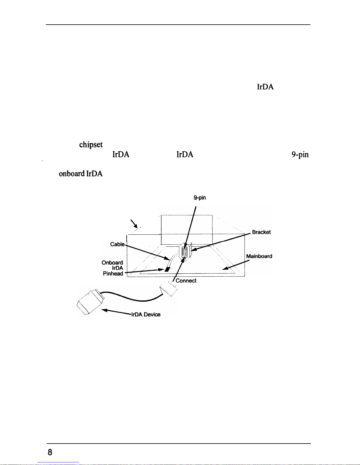
This mainboard features support for highly-sophisticated SIR technology, which
allows bi-directional and cordless data transactions with other
IrDA
compliant
computers and peripheral devices using infrared as a medium. This transmission
is carried out in either Full Duplex Mode or Half Duplex Mode. The former
allows simultaneous data transmission and reception, while the latter disables
the reception when transmission occurs.
The I/O
chipset
on this mainboard features a SIR interface that is fully
compliant with the
IrDA
standard. An
IrDA
device can be installed via a
9-pin
-
D-SUB connector in the rear panel of the computer which is linked by a cable to
the
onboard IrDA
pinhead, as shown in the illustration below.
g-pin D-SUB
Connector
Chassis
I
I
,*’
,-
I
x,_,konned
to
The serial port COM2 on this mainboard is designed to be a SIR compliant port.
If you wish to install the SIR connection feature, you need to adjust the BIOS
option for high-speed performance.
8
Page 15
Overview
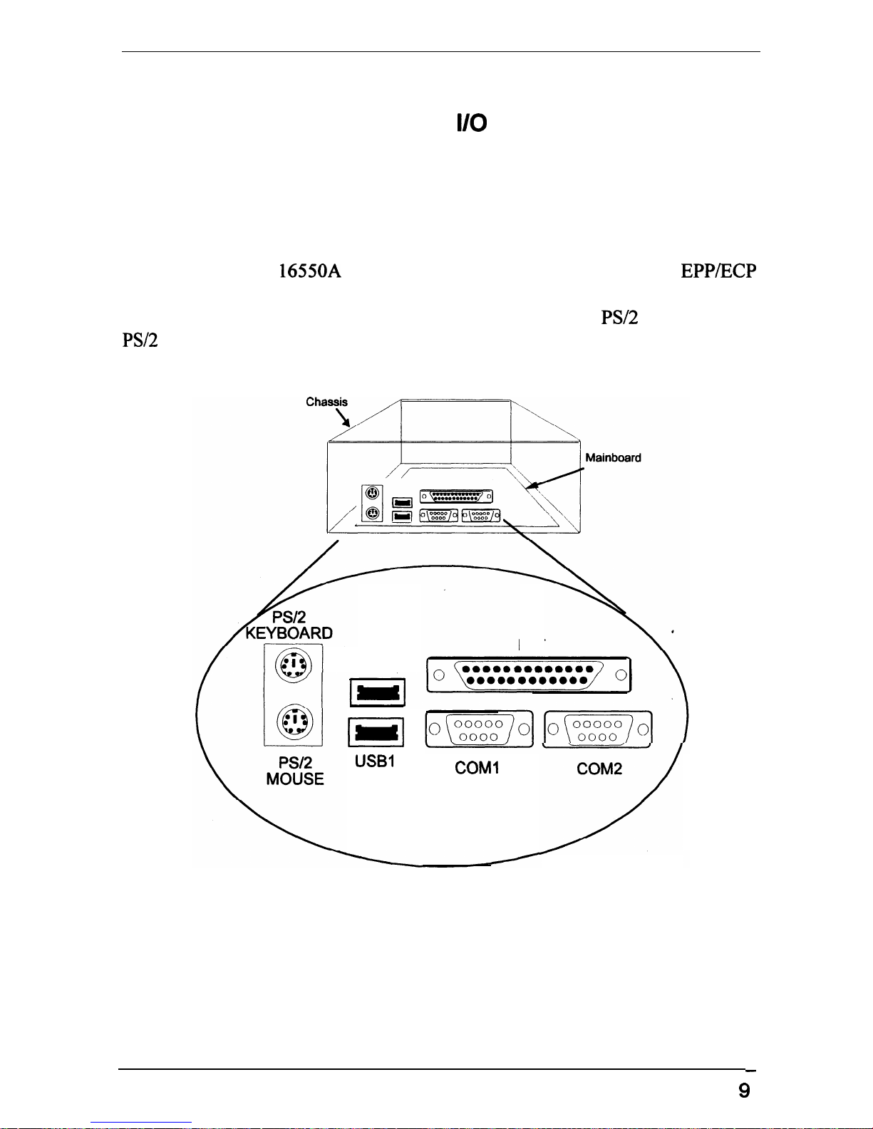
Highly Convenient Integrated
II0
Connectors
This mainboard features has an integrated rear I/O panel that incorporates a full
set of I/O ports to allow simple and convenient connections to a complete
selection of external peripheral devices.
In addition to two
16550A
UART compatible serial ports and one
EPP/ECP
capable parallel port, the panel features two USB connectors that provide high
speed connection to the next generation of USB devices.
PS/2
keyboard and
PS/2
mouse connectors provide additional I/O connectivity.
USBO
(I
USBI
LPT
COMl
COM2
:
-
9
Page 16

Installation Procedures
The PT-20 10 has several user-adjustable jumpers on the board that allow you to
cgGgure
your system to suit your requirements. This chapter contains
information on the various jumper settings on your mainboard.
To set up your computer, you should follow these installation steps:
n
Step 1
-
Set system jumpers
W
Step 2
-
Install System RAM modules
n
Step 3
-
Install the CPU
n
Step4
-
Install expansion cards
n
Step 5
-
Connect cables and power supply
W
Step 6
-
Set up BIOS feature (please read Chapter 3)
11
Page 17
PT-2010 Mainboard Manual
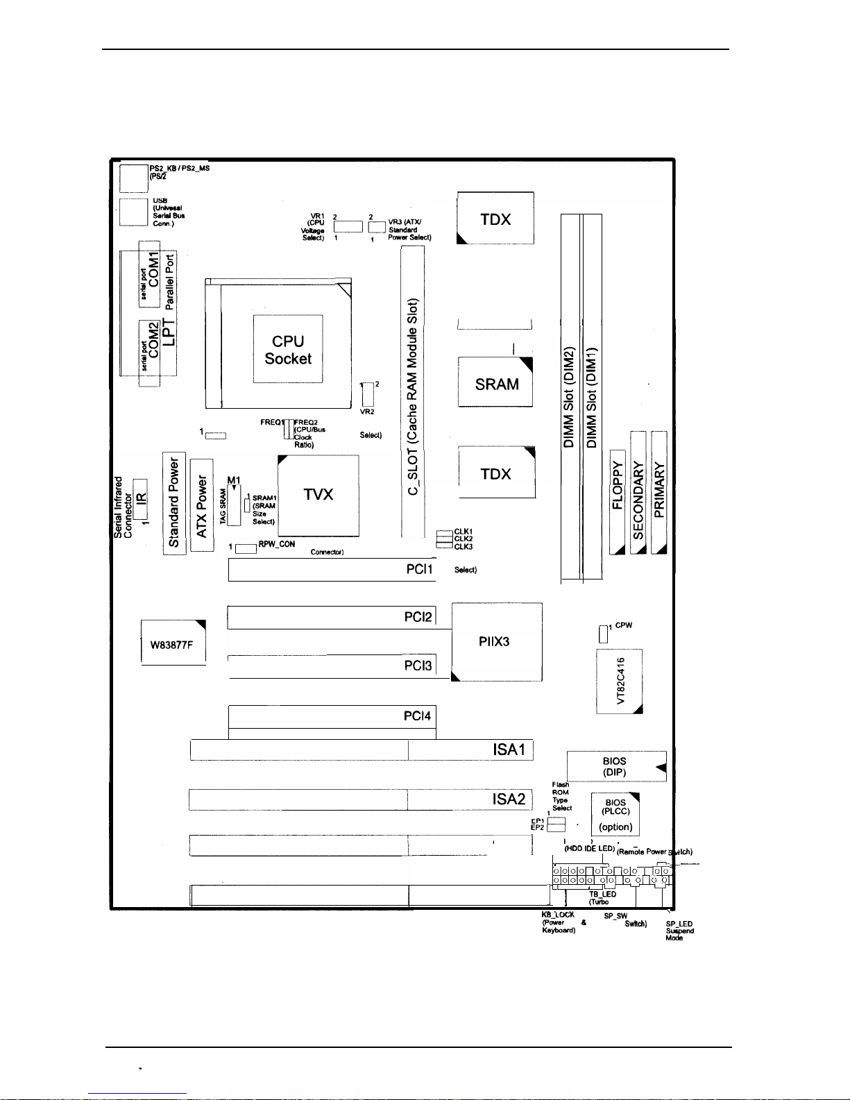
Mainboard Layout
r-l
PSZ_KB
f
PSZ_MS
(P&2 Keyboard
I Mouse Conn.)
1
1
2
/
I I
‘czl
FAN (CPU Fan)
I
u
1
VR2
FREQl
(CPU
Voltage
Select)
Ratlo)
r-
!
1
W83877F
‘I
RPW_CON
(Remote Power Come&x)
J
TDX
M2
1
SRAM
M3
1
H
CLKI
CLK2
CLK3
-
(CPU
PC11
Clock
S&d)
PC12 /
1
PC13
-
PC14
:
PllX3
I-,
0
,
CPW
(Clear
Password)
Ii-----lsAlJ
_-_____-
ISA3
j
n
IDE-LED
RPW SW
(HDD IDE LED)
(Rat&e Paver,
SPK (Speaker
I
--I
o~ojolol 10 01 lolo I Ior;-
0~0~0~0~0~
olol lo 01 [o 0
ISA4
1 ’ 1
4 u
i--J L-J
TB_LED
(Turbo
LED)
.__
.
-_._
\
KE_LOGK
(Power
LED
L
Kayboard)
SP_SW
(Suspend
Mode
SwncJl)
W
-
RST
(Hardware
Reset)
SP_LED
Slaped
Made
LED
12
-
Page 18
installation Procedures
1). Set System Jumpers
Jumpers
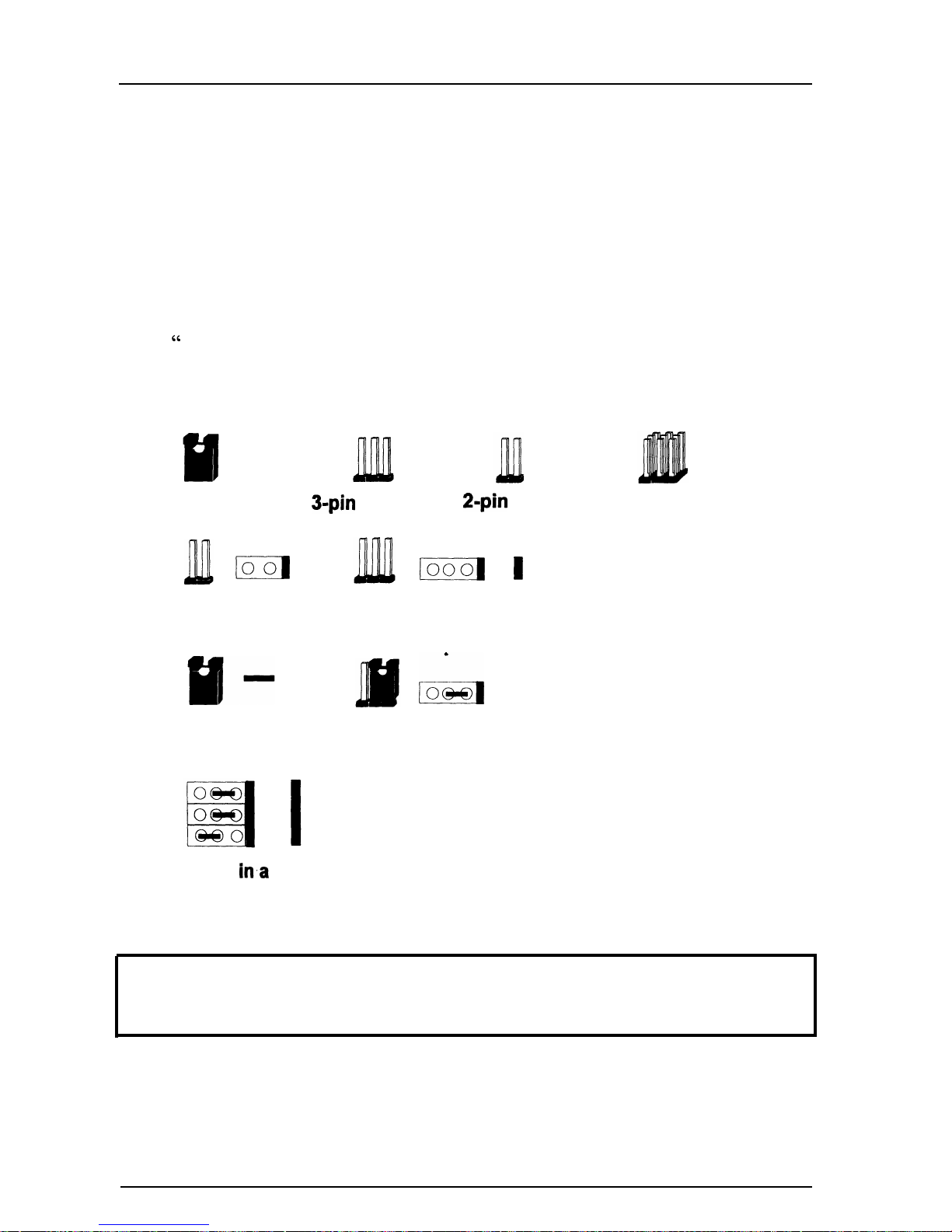
Jumpers are used to select the operation modes for your system. Some jumpers
on the board have three metal pins with each pin representing a different
function. To “set” a jumper, a black cap containing metal contacts is placed
over the jumper pin/s according to the required configuration; A jumper is said
to be “ shorted” when the black cap has been placed on one or two of its pins.
The types of jumpers used in this manual are shown below:
Jumper Cap
3-pin
Jumper
2-pin
Jumper
Jumper Block
ml
m
1
stands for pin 1
21
321
Jumpers are shown as above
&
321
Jumper cap is shown as above
stands for pin 1
Jumpers
in.a
Block
NOTE :
Users are not encouraged to change the jumper settings not listed in
this manual. Changing the jumper settings improperly may adversely affect
system performance.
13
Page 19
PT-2010 Mainboard Manual
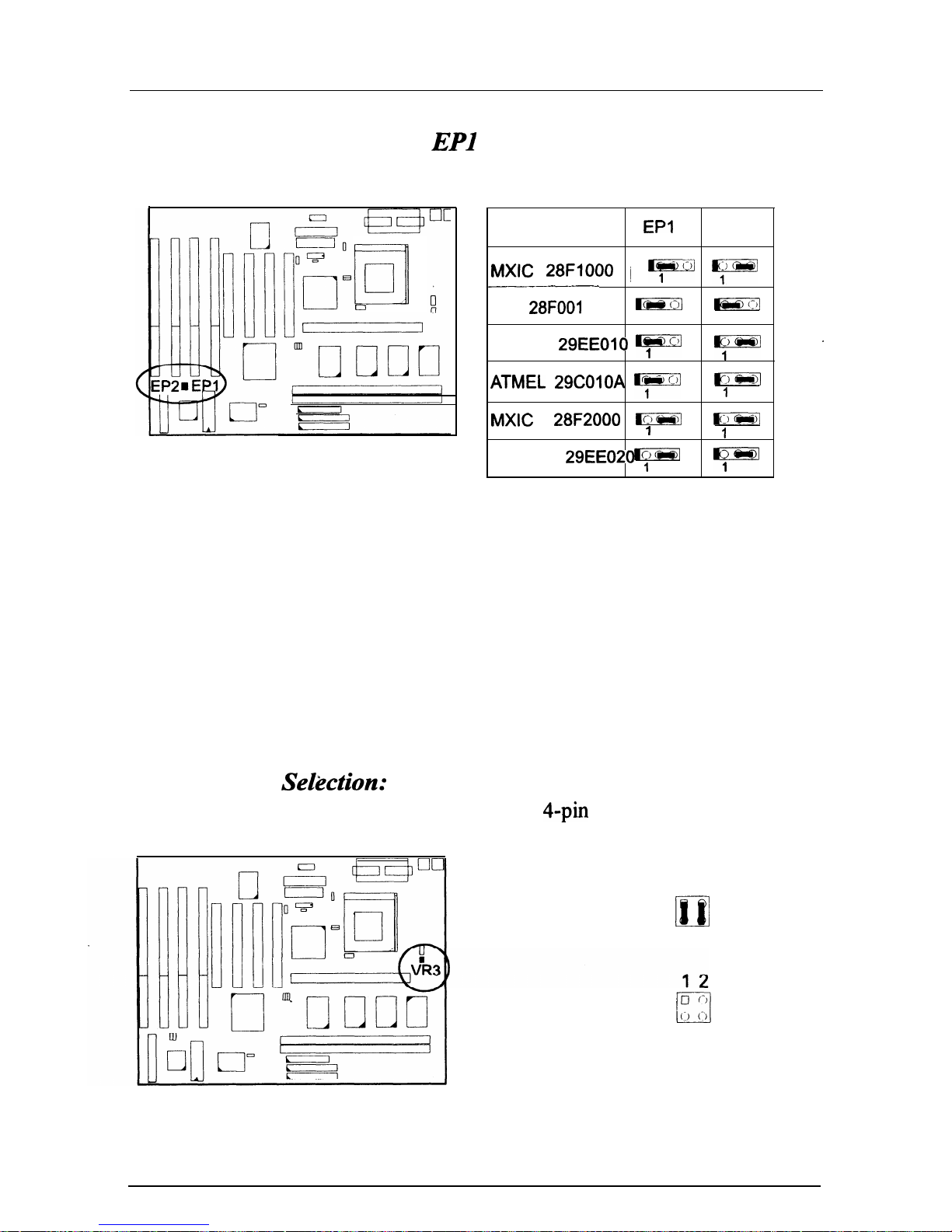
Flash ROM Type Selection:
EPl
and EP2
These two jumpers allow you to select the flash ROM type.
rl
cl
0
ROM Type
EPI
EP2
MXIC 28FlOOO
1
F
y
-~~
Intel
28FOOl
m
@is--g
1
1
SST
29EEOlO F
Y=
.
ATMEL 29COlOA y
_J
,
MXIC
28F2000
,
Ic,-‘
Er,
1
Ic,
SST 29EE020
,
F=
Power Supply
Sekction:
VR3
If you use an ATX power supply, please set this 4-pin jumper as shown below.
12
AT Power Supply
(Default)
D/
34
ATX Power Supply (9
:I:
u
34
14
Page 20
Installation Procedures
2).
Install System RAM Modules
SDRAMMemory
*
The working space of the computer is the Random Access Memory (RAM). The
system cannot act upon data unless it is loaded into RAM. When more memory
is added, the working memory of the computer is larger, thereby increasing total
performance.
The mainboard supports lightening-fast
SDRAMs
through its two
I68-pin
Dual
In-line Memory Modules (DIMM). SDRAM is an advanced new memory
technology that boosts overall system performance
with
its ability to
synchronize all operations with the processor clock signal; and speeds up
column access time.
SDRAM is an advanced new memory technology that boosts overall system
performance with its ability to synchronize all operations with the processor
clock signal.
#This
makes the implementation of control interfaces easier, and
speeds up column access time. SDRAM features an on-chip burst counter that
can be utilized to increment column addresses for very fast burst accesses,
which means that SDRAM allows new memory accesses to be initiated before
the preceding access has been finished.
Before making DRAM module upgrades you should verify the type and speed
of the RAM currently installed from your dealer. Installing mixtures of RAM
types other than those described in this manual, will have unpredictable results.
15
Page 21
PT-2010 Mainboard Manual
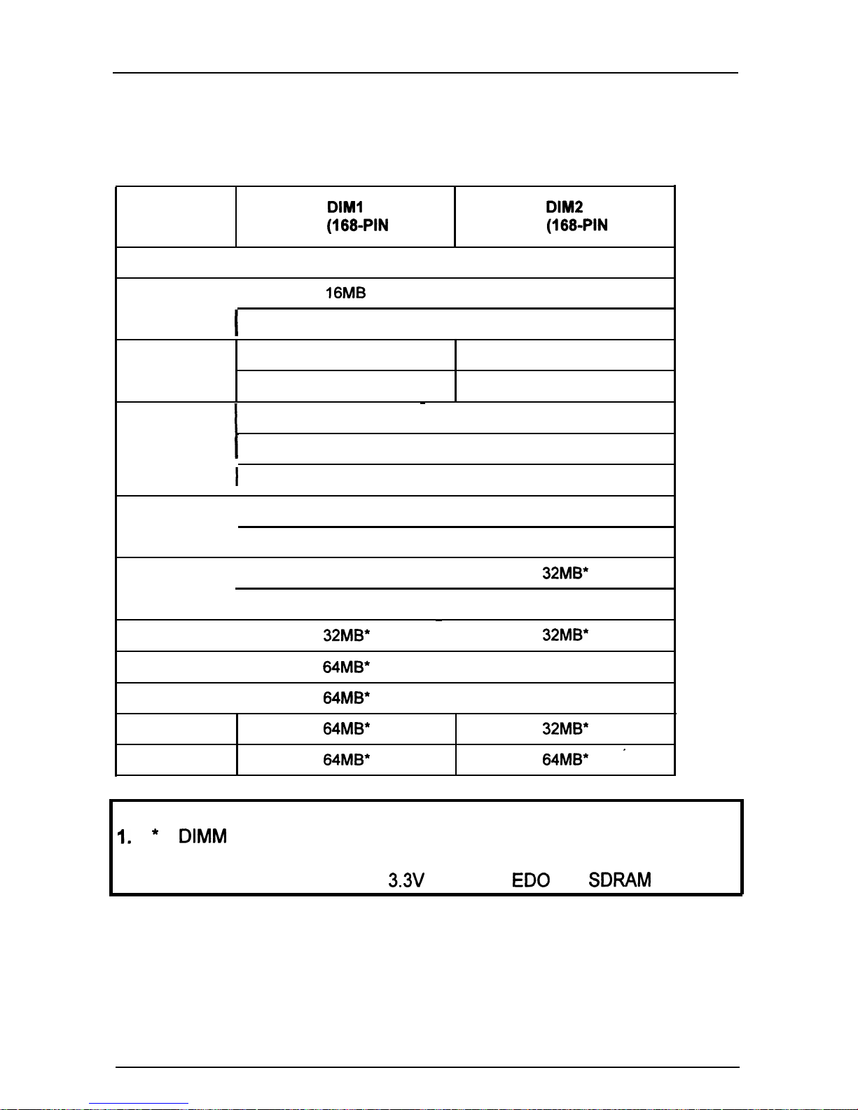
RAM Module Configuration
TOTAL
DIM1
DIM2
MEMORY
BANK0
(1680PIN
X 1)
BANK1
(1680PIN
X 1)
8MB
I
8MB
I
16MB
I
l6MB
I
I
8MB
I
8MB
24 MB
8MB 16MB
24MB
32MB
1
32MB
~
I
I
8MB
I
24MB ,
I
16MB
I
16MB
40MB
I
8MB
I
32MB
I
16MB
I
24MB
48MB
I
16MB
I
32MB*
I
24MB
I
24MB
64MB
I
32MB*
~
I
32MB*
72MB
I
64MB*
I
8MB
80MB
I
64MB*
I
16MB
96MB 64MB* 32MB*
128MB 64MB* 64MB*
*
NOTE :
I.
*
A
DIMM
of this size was not available for testing when this book
was printed.
2.
DIM1 and
DIM2 only support
3.3V
(unbuffer) ED0 and
SDFWM
modules.
16
Page 22
installation Procedures
Install
DlMMs
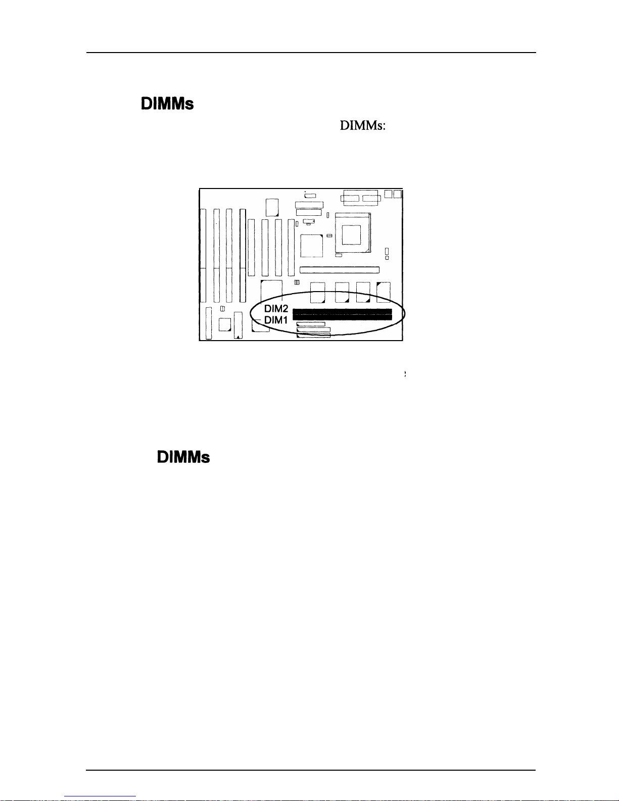
Complete the following procedures to install
DIMMs:
1.
Locate the DIMM slots on the mainboard. (See figure below.)
2. Insert the DIMM straight down onto the DIMM
carefully until the clips on the ends of the slot close
firmly.
Remove
DlMMs
:
slot with both hands
up to hold the DIMM
Press the clips on the ends of the slot with both hands. The DIMM will spring
out easily.
17
Page 23
PT.201
0 Mainboard Manual
Cache Memory
Cache memory access is very fast compared to main memory access. The cache
holds data for imminent use. Since cache memory is five to more than ten times
faster than main memory, the CPU’s access time is reduced, giving you better
system performance.
Pentium mainboards may implement various types of L2 cache SRAMs.
Pipeline Burst SRAM is one of them, delivering the best price performance
ratio. They perform much better than asynchronous SRAMs.
The specification of the SRAM module requires Intel Coast Standard version
3.X, such as
FIG’s PB512K-3.0.
The PT-2010 comes with
onboard 256/5
12KB synchronous 3V Pipeline Burst
SRAMs, and one optional
256/5
12KB SRAM module
(FIG’s PBS 12K-3.0
is
recommended) that can be installed on the SRAM module slot.
I
NOTE :
Use
the correct chips for the amount of cache memory you want to
add. Install both the correct SRAM module and
tag
SRAM.
.
I
18
Page 24
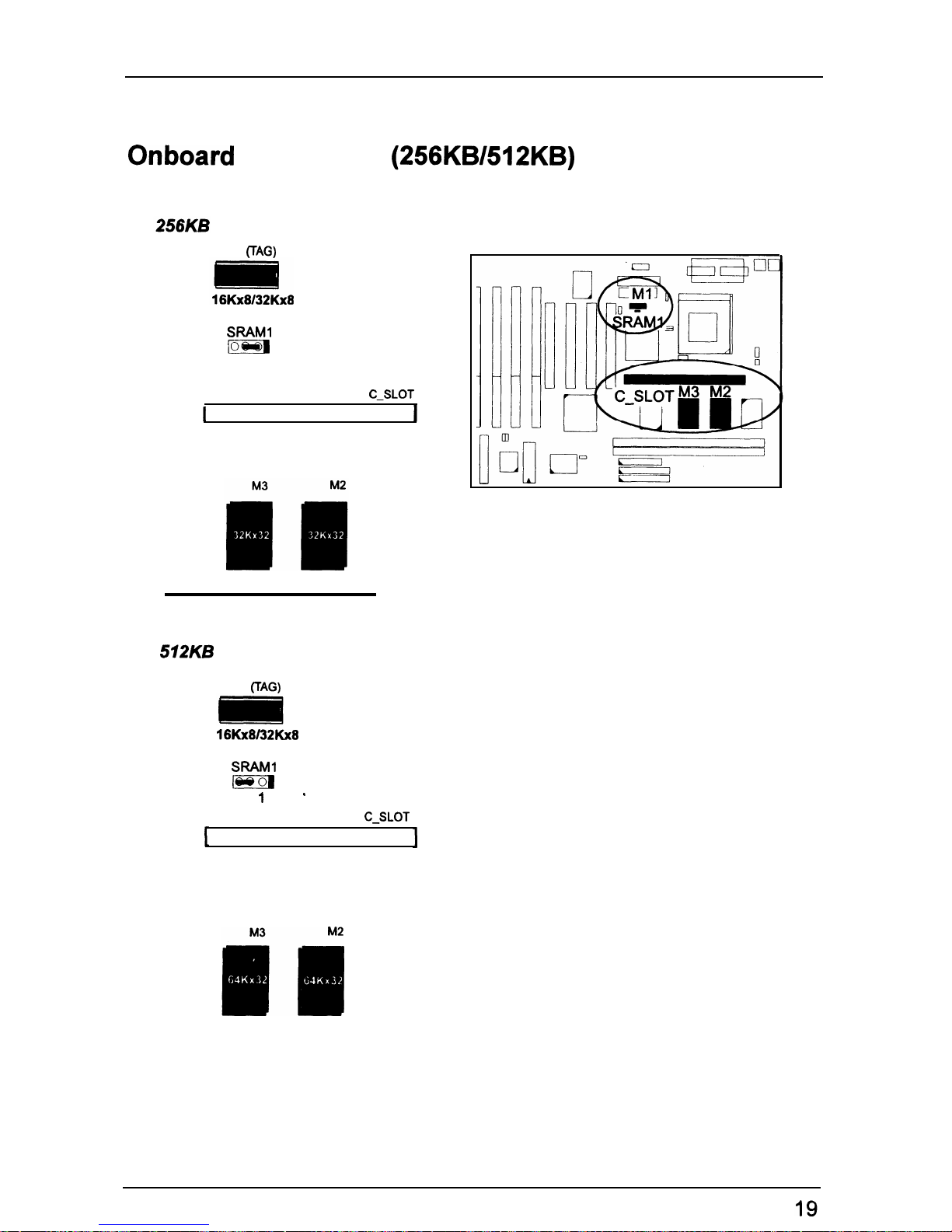
Installation Procedures
Onboard Cache RAM (256KBl512KB)
Ml
FAG)
Sfuwl
lo
C-SLOT
I
I
512KB
Ml
CT.G)
16Kx8132Kx8
SfwhAl
lee
1
’
C-SLOT
Page 25
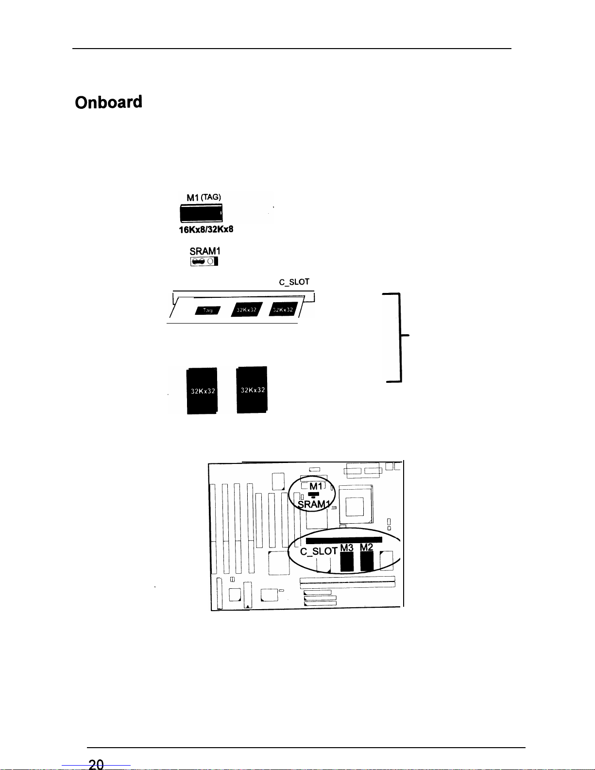
PT-2010 Mainboard Manual
Onboard Cache RAM and SRAM Module Mixture
(512KB)
16Kx8132Kx8
Sf3AMl
lisEiB
1
C-SLOT
M3
M2
.161
.
I
i
256KB
512KB
256KB
20
Page 26
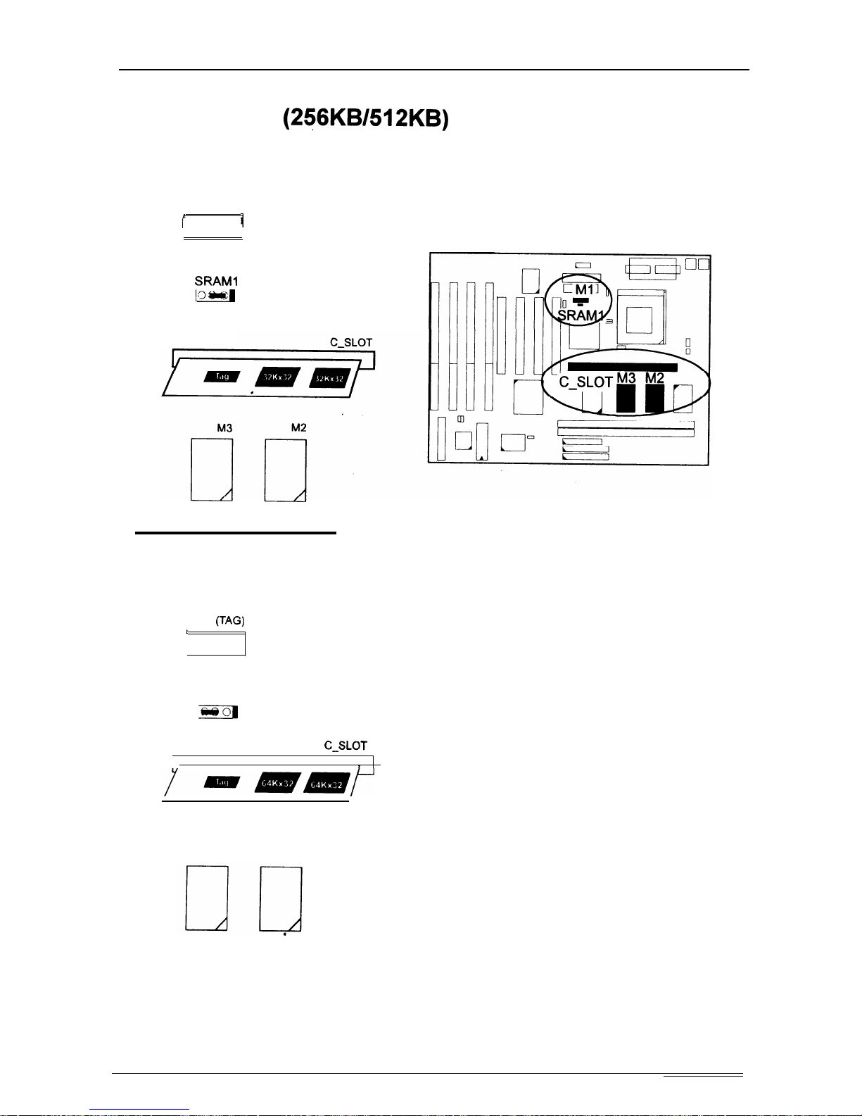
Installation Procedures
SRAM Module
(236KBM2KB)
256KB
Ml (TAG)
1
1
SRAMI
lom(
1
512KB
Ml
(TAG)
I
SRAMI
BsB
1
C-SLOT
I,
I
M3
M2
21
Page 27
PTy201
0 Mainboard Manual
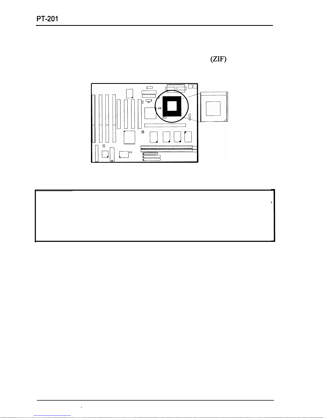
3). Install the CPU
The CPU module resides in the Zero Insertion Force
@IF)
socket on the
mainboard.
CAUTION :
1. Always turn the system power off before installing or removing any
device.
2.
Always observe static electricity precautions.
See “Handling Precautions” at the start of this manual.
3.
Inserting the CPU chip incorrectly may damage the chip.
To install the CPU, do the following:
1.
Lift the lever on the side of the CPU socket.
2.
Handle the chip by its edges and try not to touch any of the pins.
3.
Place the CPU in the socket. The chip has a notch to correctly orientate the
chip. Align the notch with pin one of the socket. Pin one is located in the
blank triangular area. Do not force the chip. The CPU should slide easily
into the socket.
4.
Swing the lever to the down position to lock the CPU in place.
5.
See the following sections for information on the CPU jumpers settings.
22
.
Page 28
.
Installation Procedures
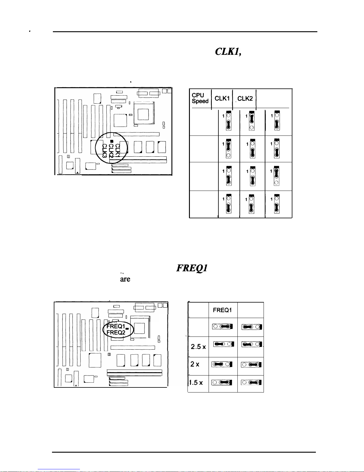
CPU External Clock (BUS) Frequency:
CLKl,
CLK2, and’CLK3
The table below shows the jumper
configurations.
settings for the different CPU speed
E;,ed 1 CLKl 1
,CLK2 j CLK3
66 MHz
60 MHz
‘!I
‘Ii
‘Iii!
55 MHz
‘B
‘1
‘!!I
50 MHz
I I
I
CPU to Bus Frequency Ratio:
FREQl
and FREQ2
These two jumpers &e used in combination to decide the ratio of the internal
frequency of the CPU to the bus clock.
II
0
Ratio FREQI
FREQ2
3x
lo
@EBB
1
1
25x
w
[eo.
.
1
1
2x
ps-DD -1
1 1
1.5x
D-@a
LO
1 1
23
Page 29
PT.201
0 Mainboard Manual
.
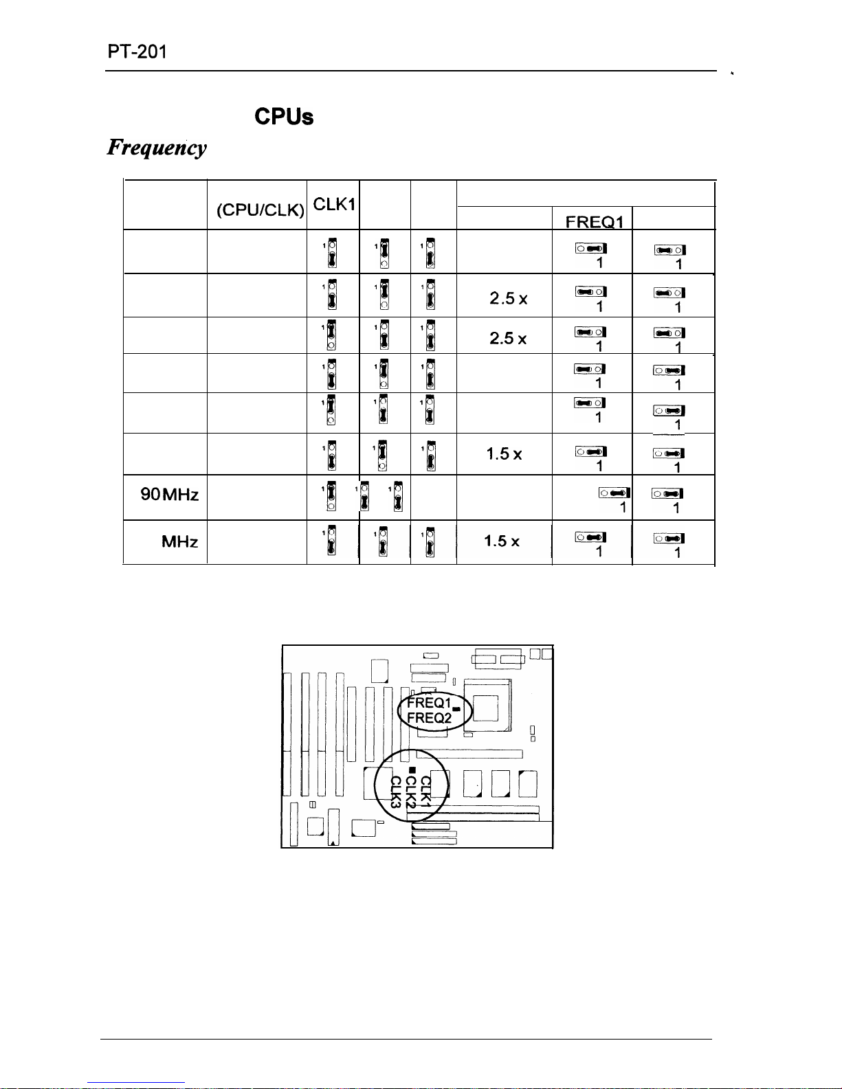
Intel Pentium CPUs
Frequenky
CPU
External
Speed
(CPWCLK)
CLKl CLK2 CLK3
CPU Clock Rate
Internal
FREQI
FREQ2
l
200 MHz
66 MHz
‘B
‘6 ‘1
3 x
7
7
-
166
MHz
66 MHz
‘1
‘[
‘1
2.5x
7
7
150
MHz
60
MHz
‘[
‘1
‘[
2.5x
““;’
7
.
133 MHz
66 MHz
‘B
‘ij
‘[
2 x
y
%y
120
MHz 60 MHz
‘[
lij
‘[
2x
7
IE-iiiiq
100
MHz
66
MHz ‘1
qij
‘1
1.5x
y
4
90MHz
60 MHz
‘B ‘B
‘1 1.5x
7
y
75
MHz
50
MHz
24
Page 30
Installation Procedures
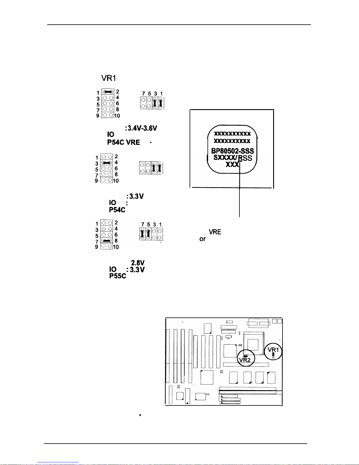
Voltage
VRl
VR2
8642
Core : 3.4W3.W
IO
: Same
P54CVRE
.
7531
0 0
m
0 Cl
8642
Core :
3.3V
IO
:
Same
P54C
STD
8642
Core :
2.8V
IO
:
3.3v
P55C
Intel Pentium CPU
Bottom Side Marking
xmcxxxxxxx
BP805021SSS
R (Identifier for Voltage Range)
:
V for
VRE
Voltage Range
Of-
S for Standard Voltage Range
25
Page 31
PT-2010 Mainboard Manual
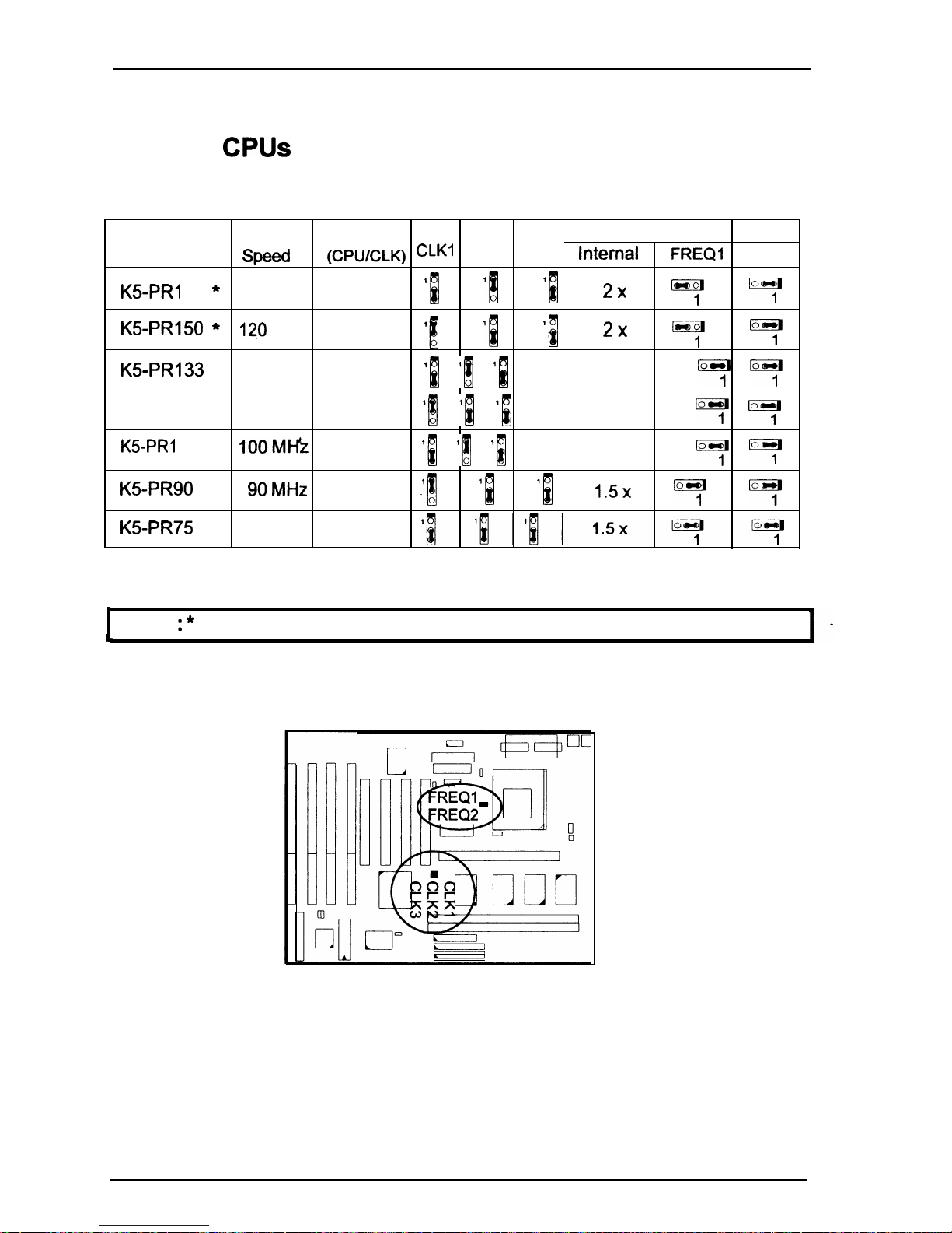
AMD-K5 CPUs
Frequency
Model
CPU
External
CPU Clock Rate
Name
Speed
(CPWCLK)
CLKI
CLK2 CLK3
Internal
FREQI
FREQ2
KSPRI 66 *133
MHz
66 MHz
‘B
‘B ‘B 2)( ““;’
y
KS-PR150 *
120
MHz 60 MHz
‘l
‘1 ‘5 2x
Eyl
7
K5-PR133
100 MHz
66 MHz
‘1 ‘[ ‘[
1.5x
7
y
KS-PRI 20
90 MHz
60 MHz
‘[ ‘[ ‘1
1.5x
7
7
KS-PRl
00
lOOMI+
66 MHz
‘B ‘B ‘i
1.5x
y
“I:
K5-PR90
90MHz
60 MHz
.I[ ‘[ ‘B
1.5x
““:
7
K5-PR75
75
MHz
50 MHz
NOTE : * This CPU had not been tested when this manual was printed.
26
Page 32

Installation Procedures
Voltage
VRI
VR2
7531
0 0
m
00
8642
Core :
3.4W3.6V
IO
:
Same
AMIEK5 -
B
a 6
4,2
Core : 3.W
IO : Same
AMD-KS -
C, F
7531
0 0
m
0 0
8642
Core
: 2.9V
IO
:
3.3v
AMD-KS - H
1 p--q
2
7531
c’
0
m
00
8642
Core
:
2.W
IO
:
3.3v
AMD-KS- J .
7531
8642
Core :
2.5V
IO : 3.3v
AMD-K5 -
K
AMD-KS CPU
Top Side Marking
AMD-K5
AMD-KS-PRXXXAF
v (Identifier for Operation Voltage)
:
B
C
F
Please refer to
H
the left-hand-side table
J
K
27
Page 33
PT.201
0 Mainboard Manual
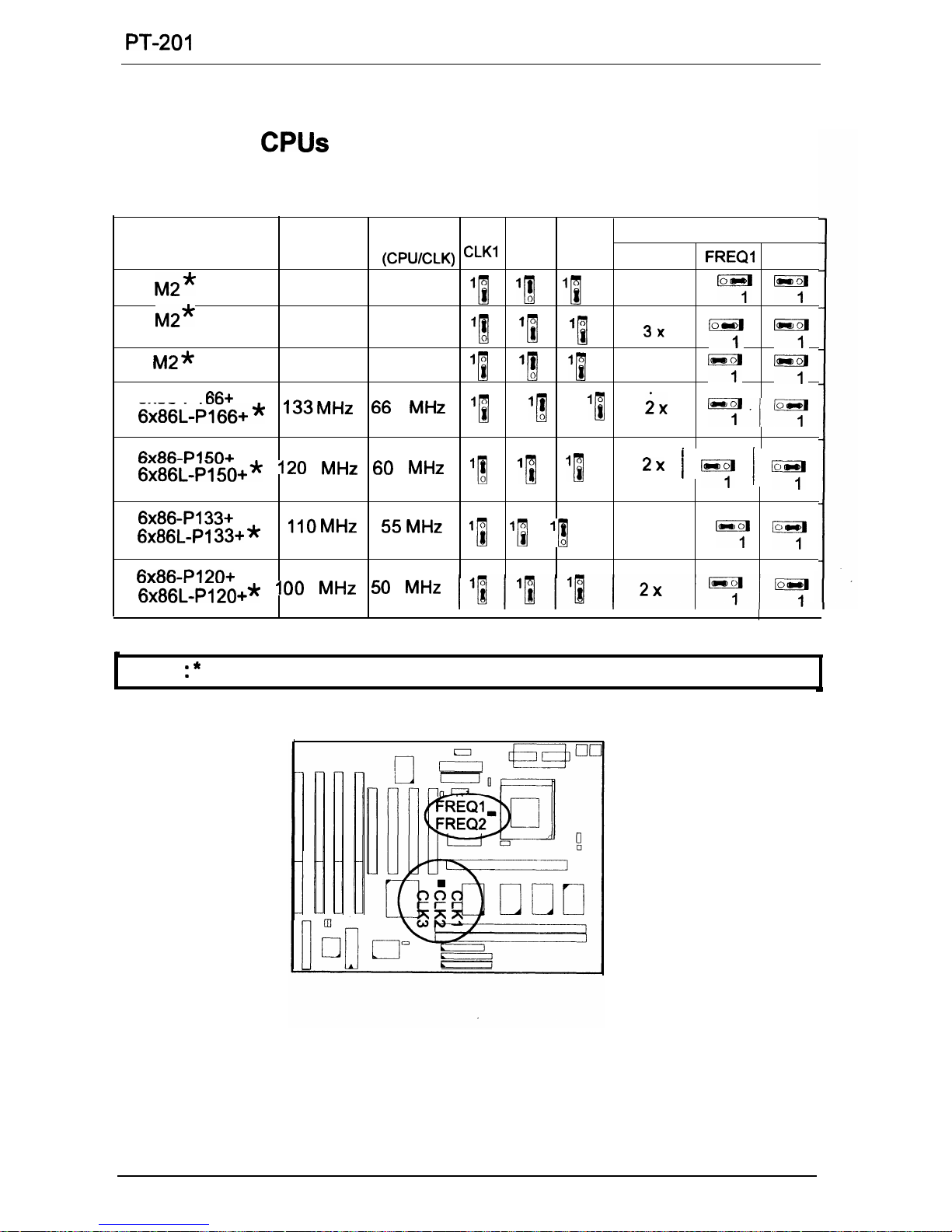
Cyrix 6x86 CPUs
Frequency
Model
CPU
External
CPU Clock Rate
Name
Speed
(CPWCLK)
CLKI
CLK2 CLK3
Internal
FREQI FREQ2
M2*
200 MHz 66 MHz
‘1 ‘1
‘1
3x
y
y
M2*
180
MHz
60
MHz
11
‘1
‘i
3x
‘“r;’
yB
M2*
166
MHz
66
MHz
‘N
‘Ilfl
‘i
2.5x
7
y
6x86-PI
66+
&o&L_p1fjfj+* ‘33MHz 66 MHz
‘fj
11 ‘[
i)(
y-y
6x86-P150+
&o&L_p15()+* ‘20 MHz 60
M-k
‘1 ‘4
‘i
2x /
kyl 1 yl
6x86-P133+
.
6x86L-PI 33+ *
1lOMHz 55MHz
‘1 ‘1 ‘1
2x
““:
@yl
6x86-P120+
6~86L-P120+* loo MHz 5o MHz
.
NOTE : * This CPU had not been tested when this manual was printed.
28
Page 34
Installation Procedures
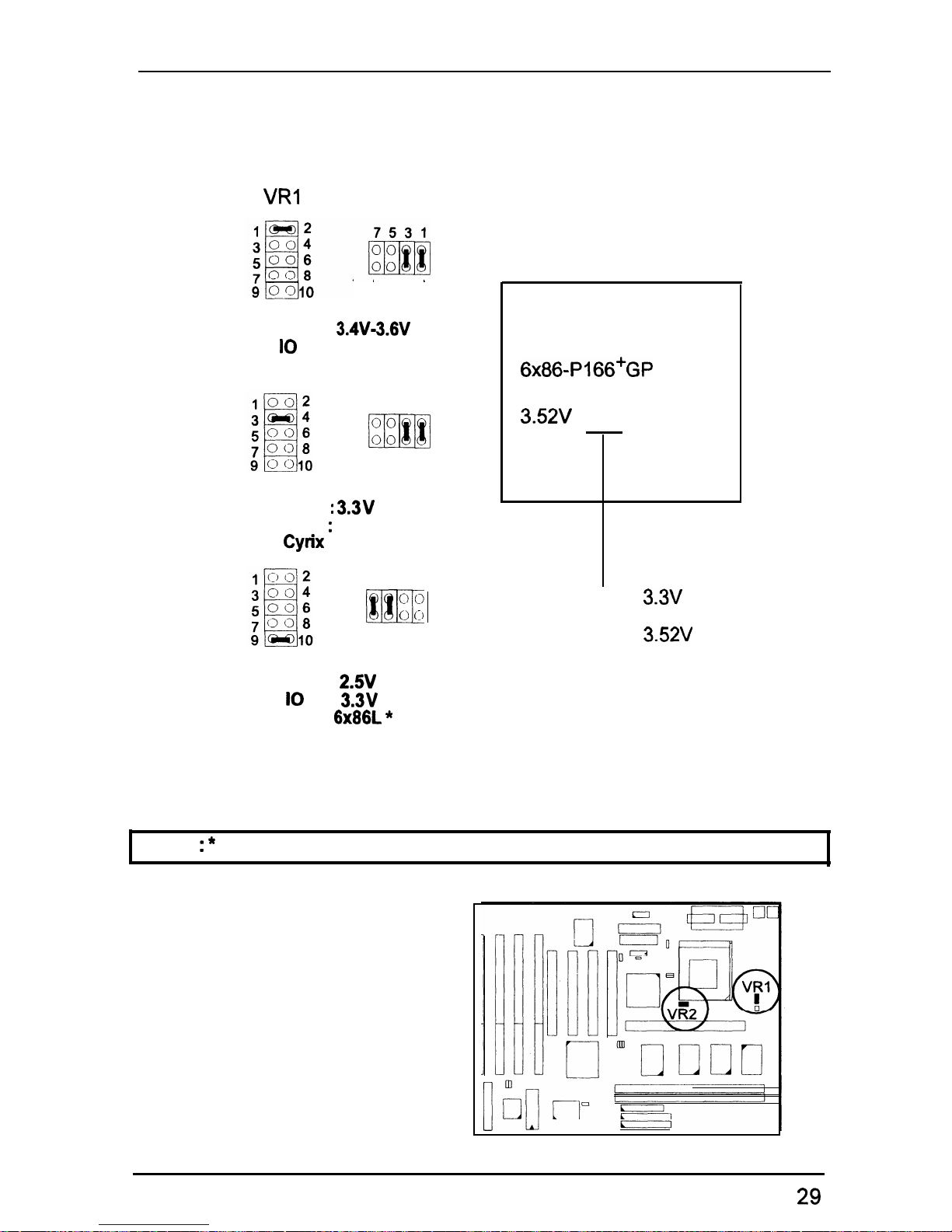
Voltage
VRI
VR2
8642
Core :
3.4V-3.6V
IO : Same
Cryix 6x86-028
7531
00
m
00
8642
Core :
3.3V
IO
:
Same
cyrix 6x86-016
7531
0
0
m
0 (1)
8642
Cyrix 6x86 CPU
Top Side Marking
6x86-P166+GP
133 MHz
3.52V
(028)
(016) :
3.3V
(028) :
3.52V
core :
2.w
IO
: 3.3v
Cyrix
6x86L *
NOTE : * This CPU had not been tested when this manual was printed.
29
Page 35
PT-2010 Mainboard Manual
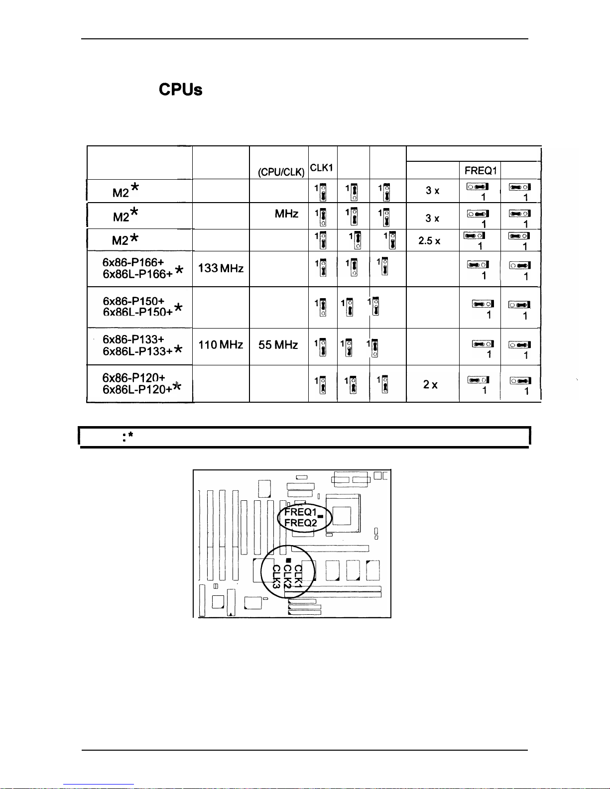
IBM 6x86 CPUs
Frequency
Model
Name
I
M2*
I
M2*
I
M2*
6x86-P120+
6X86L-Pl 20+J
CPU
External
CPU Clock Rate
Speed
(CPUICLK)
CLKl
CLK2 CLK3
Internal
FREQl FREQ2
200 MHz
66
MHz
11
11
1B
3X
by
,
Lyl
180 MHz
60
MHz
‘1
q
1N
3x
yl
y.B
166 MHz 66 MHz
‘B
‘1 q
2.5x
y
yJ
133MHz
66 MHz
‘p/J’0
2x
7”““:
120 MHz
60
MHz
q ‘B q
2x
key by
IlOMHz 55MHz
‘[ ‘i ‘1
2x
7
by
100 MHz
50
MHz
1
NOTE : * This CPU had not been tested when this manual was printed.
1
30
Page 36
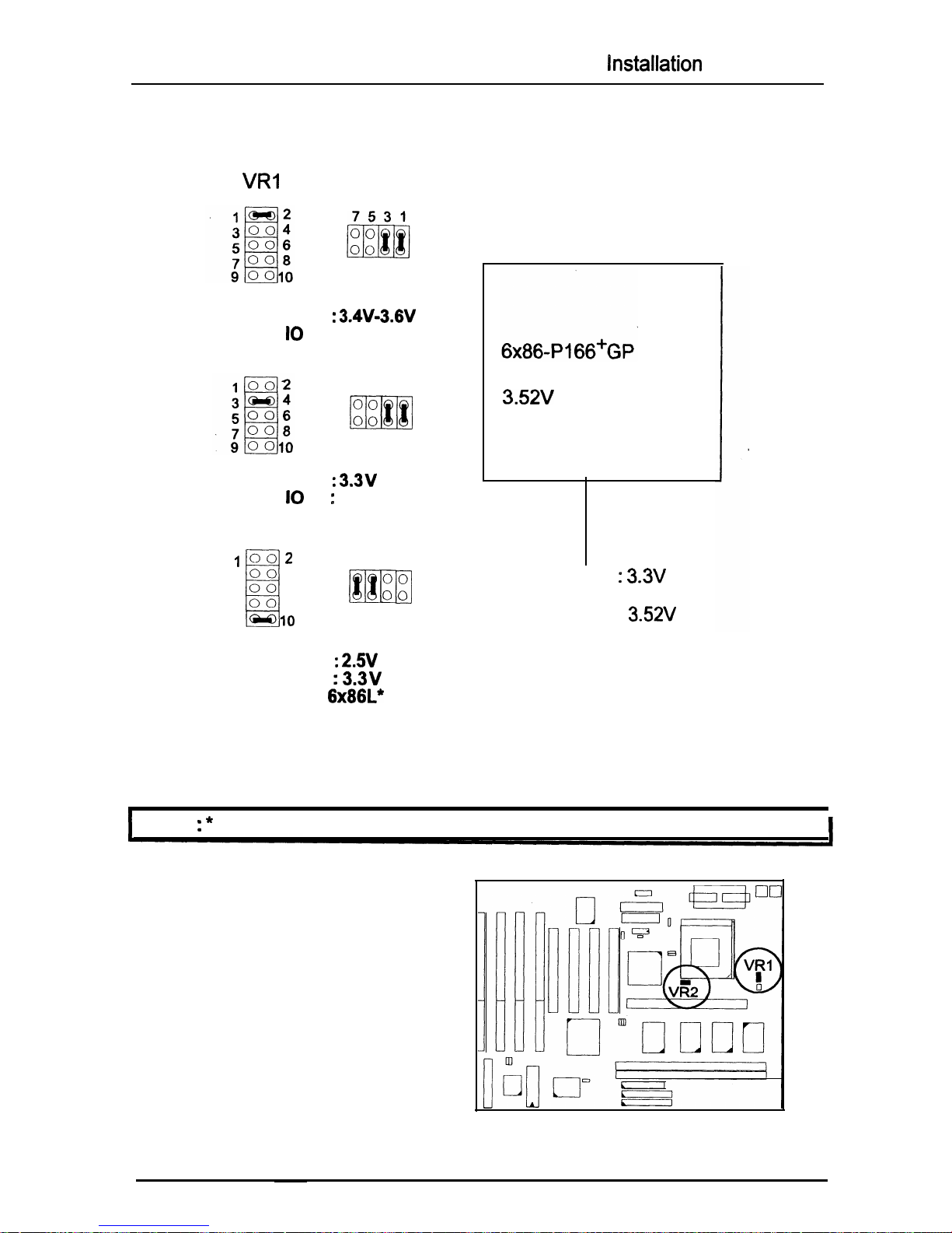
ilnstallation
Procedures
Voltage
VRI
VR2
8642
Core :
3.4W3.6V
IO : Same
IBM 6x86-028
7531
00
m
00
8642
Core :
3.3V
IO: Same
IBM 6X86-01 6
1002
3004
5006
i
7008
9
-10
7531
00
m
00
8642
Core :
2.5V
IO
:
3.3v
IBM
6x86L”
IBM 6x86 CPU
Top Side Marking
133 MHz
3.52V
(028)
T
(016)
: 3.3V
(028) :
3.52V
1
NOTE : * This CPU had
not been tested when
this
manual was printed.
31
Page 37
PT-2010 Mainboard Manual
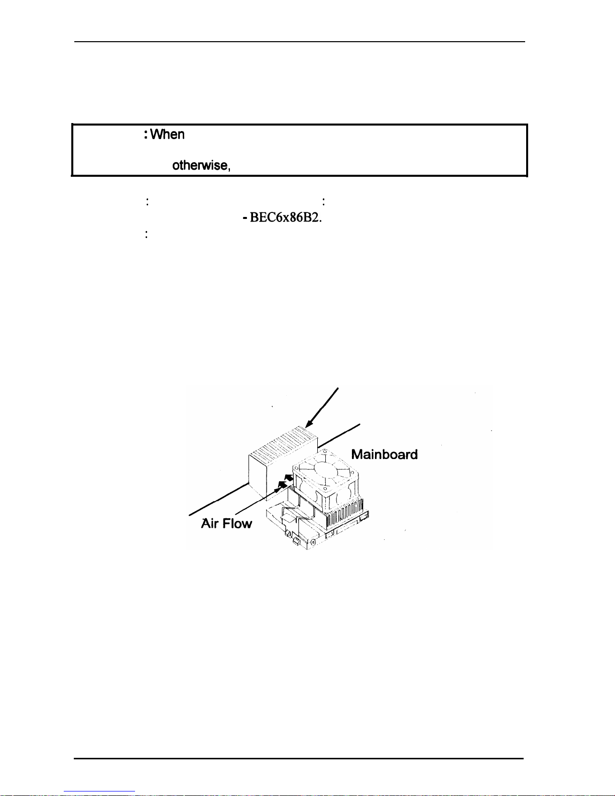
Installation of Cyrix (or IBM) 6x86 CPU Fan
CAUTION :
VVhen
you install a Cyrix (or IBM) 6x86 CPU fan, please pay
attention to the direction of the air flow. Make sure the air flow is the direction
of the regulator;
othewvise,
the system may overheat.
1). Supplier : BIRCHTECK, Taiwan (Phone : 886-2-7935677)
Model Number -
BEC6x86B2.
2). Supplier : Cyrix (or IBM). The fan comes with the Cyrix (or IBM) 6x86
CPU purchase. For the stable system performance, make sure
that the air flow blow toward the regulator the temperature
of the regulator.
Regulator
Heat Sink
32
Page 38
Installation Procedures
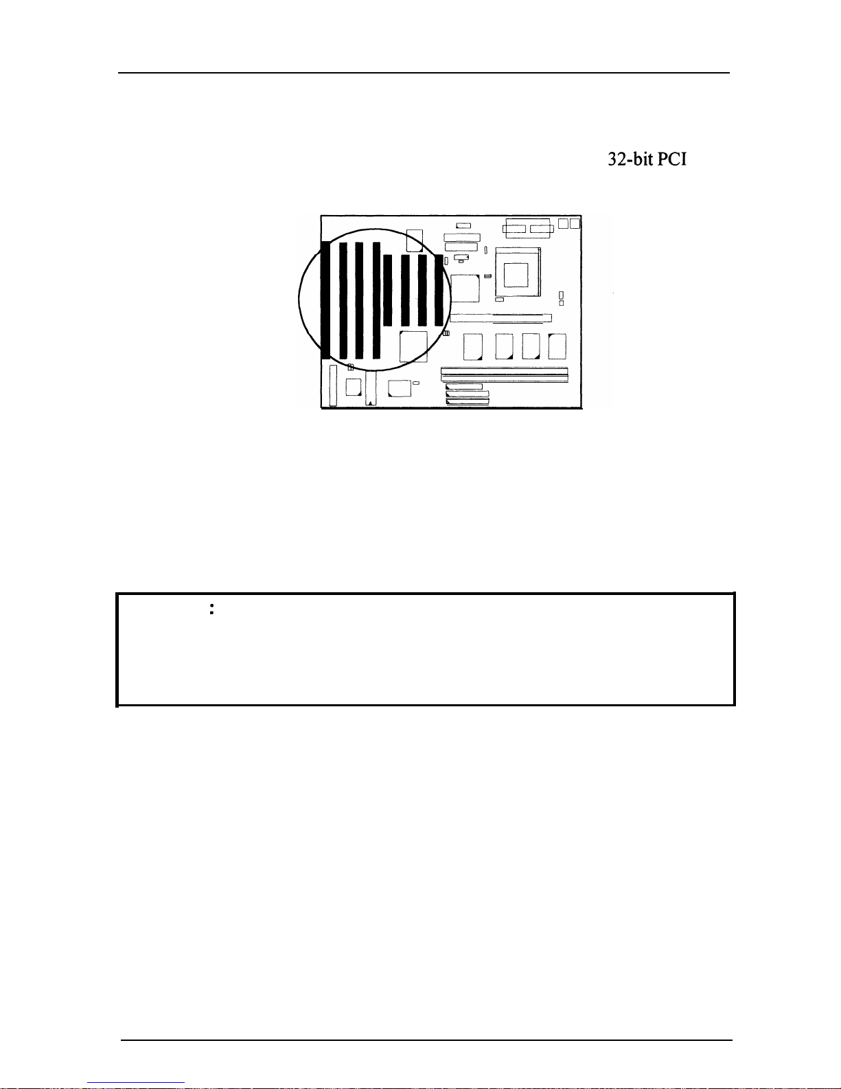
4). Install Expansion Cards
Your mainboard features four lo-bit ISA Bus and four
32-bit PC1
Bus
expansion slots.
This section describes how to connect an expansion card to one of your system’s
expansion slots. Expansion cards are printed circuit boards that, when connected
to the mainboard, increase the capabilities of your system. For example,
expansion cards can provide video and sound capabilities.
CAUTION
:
1. Always turn the system power off before installing or removing any
device.
2.
Always observe static electricity precautions.
See “Handling Precautions” at the start of this manual.
To install an expansion card, do the following:
1.
Remove the chassis cover and select an empty expansion slot.
2.
Remove the corresponding slot cover from the chassis.
Unscrew them mounting screw that secures the slot cover and pull the slot
cover out from the chassis. Keep the slot cover mounting screw nearby.
33
Page 39
PT-2010 Mainboard Manual
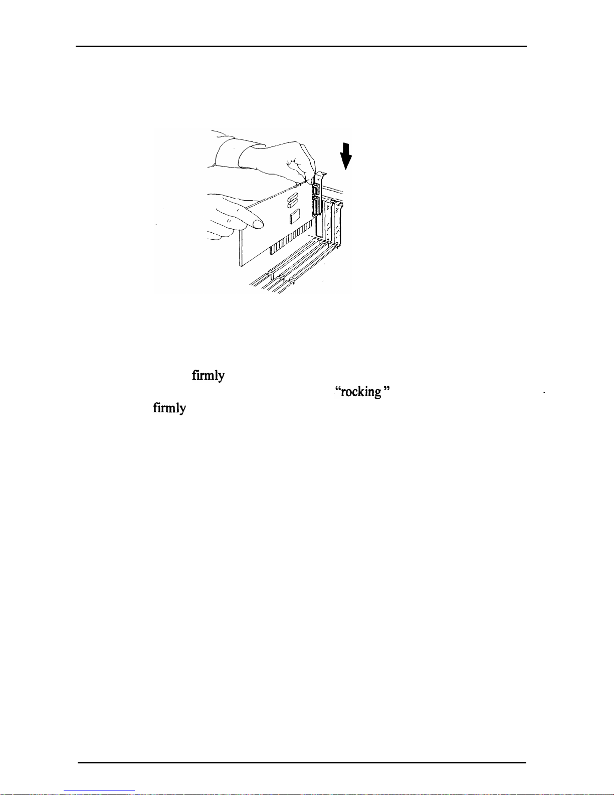
3.
Holding the edge of the peripheral card, carefully align the edge connector
with the expansion slot. (See figure below.)
4.
Push the card
firmly
into the slot. Push down on one end of the
expansion card, then the other. Use this
,“rocking ”
motion until the add -in
a
card is
firmly
seated inside the slot.
5.
Secure the board with the mounting screw removed in Step 2.
Make sure that the card has been placed evenly and completely into the
expansion slot.
34
Page 40
Installation Procedures
5). Connect Cables and Power Supply
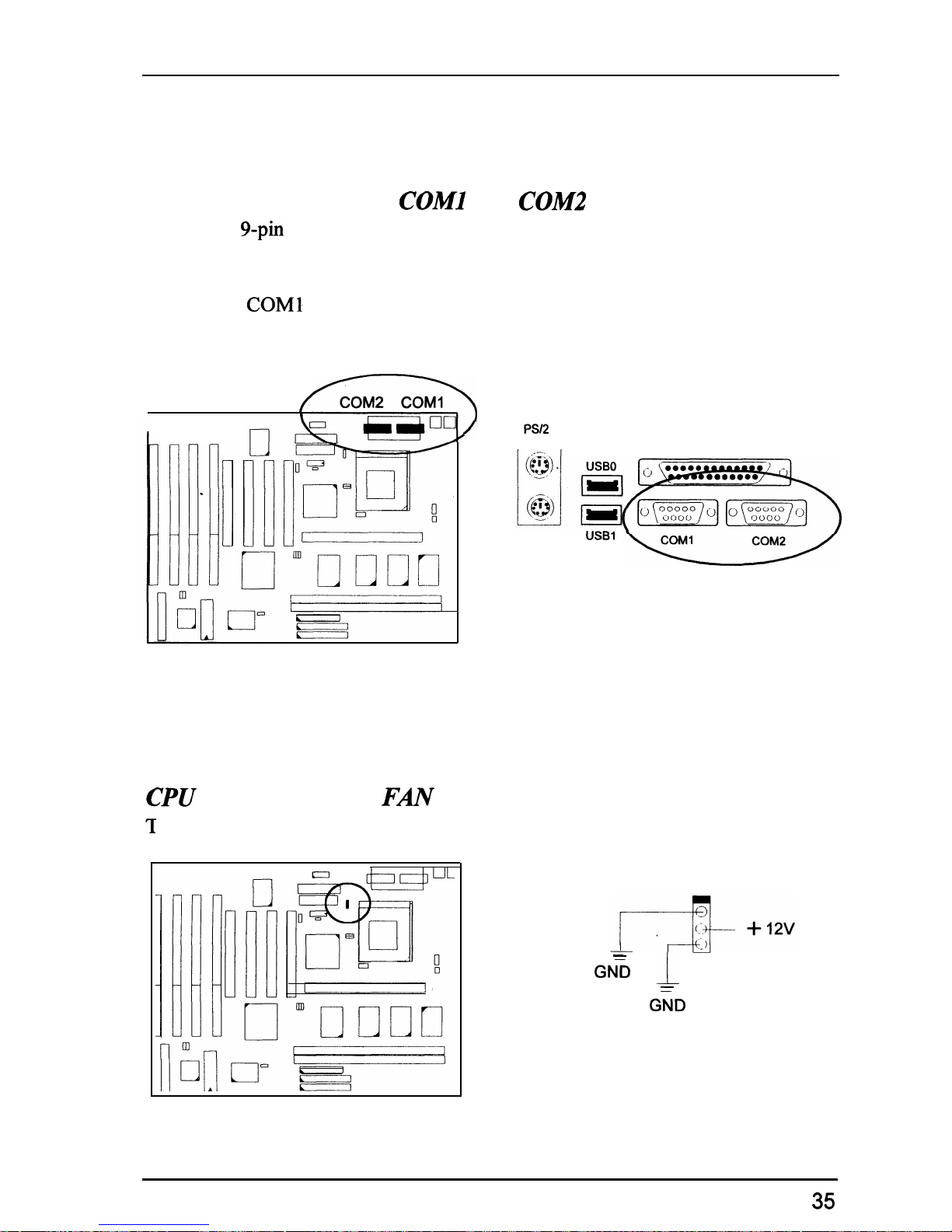
Serial Port Connector:
COMl
and
COM2
These two
g-pin
D-Sub male connectors allow you to connect with your devices
that take serial ports, such as a serial mouse or a modem. The COM2 Port on the
mainboard can also be used as another IR Port. Usually, your serial mouse is
attached to
COMl
. Your modem is linked to COM2. When you do not use the
modem, you can set the BIOS to let COM2 be an IR port to save a dedicated
/
COM2 COMI
I
[
/
PSI2
KEYBOARD
--
SIR port.
YPU
Fan Connector:
Fm
his connector is linked to the CPU fan.
PSI2
MOUSE
PRINTER
USBl
-
GNi
1
-
GiD
35
Page 41
PT-2010 Mainboard Manual
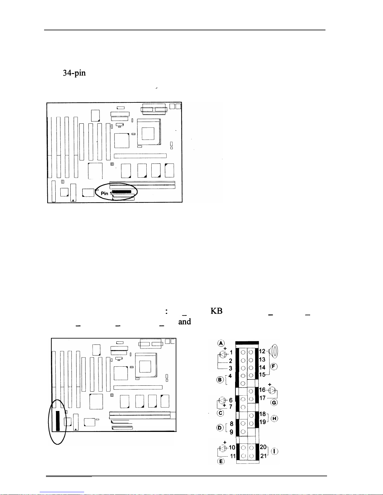
Floppy Diskette Drive Connector: FLOPPY
This 34.pin block connector connects to your floppy diskette drive (FDD) using
the cable that is provided with this mainboard.
*
Front Panel Block Connector: F PNL
This block connector concludes
:
PW-LED,
KI3
LOCK, TB LED, SP SW,
SPK, SP LED, IDE LED, RPW SW,
aid
RST connectors.
-
-
- - -
I
L
J
01
B
-4
5
O[
D
8
9
36
Page 42
Installation Procedures
*
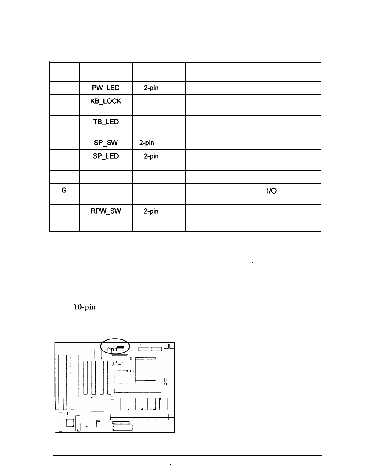
Item
Connector
Pin Type Feature
A
PW_LED 2-pin
male
indicates the system power status
B
KB_LOCK 2-pin male
allows the keyboard to access the
system
C
TB_LED 2-pin male
indicates the system speed is in
normal or turbo speed
D
SP_SW
.
2-pin
male
Suspend Mode switch
E
SP_LED
2-pin
male
indicates the system into Suspend
Mode when LED lit
F
SPK 4-pin male
connects to speaker
G
IDE-LED 2-pin male
indicates the IDE HDD
I/O
access
LED lit
H
RPW_SW
2-pin
male
Remote Power switch
I
RST
2-pin male
allows you to reset the system
Infrared Connector: IR
This
IO-pin
male connector is used for connecting to the infrared (SIR) port and
allows transmission of data to another system which also supports the SIR
feature.
.
37
Page 43
PT-2010 Mainboard Manual
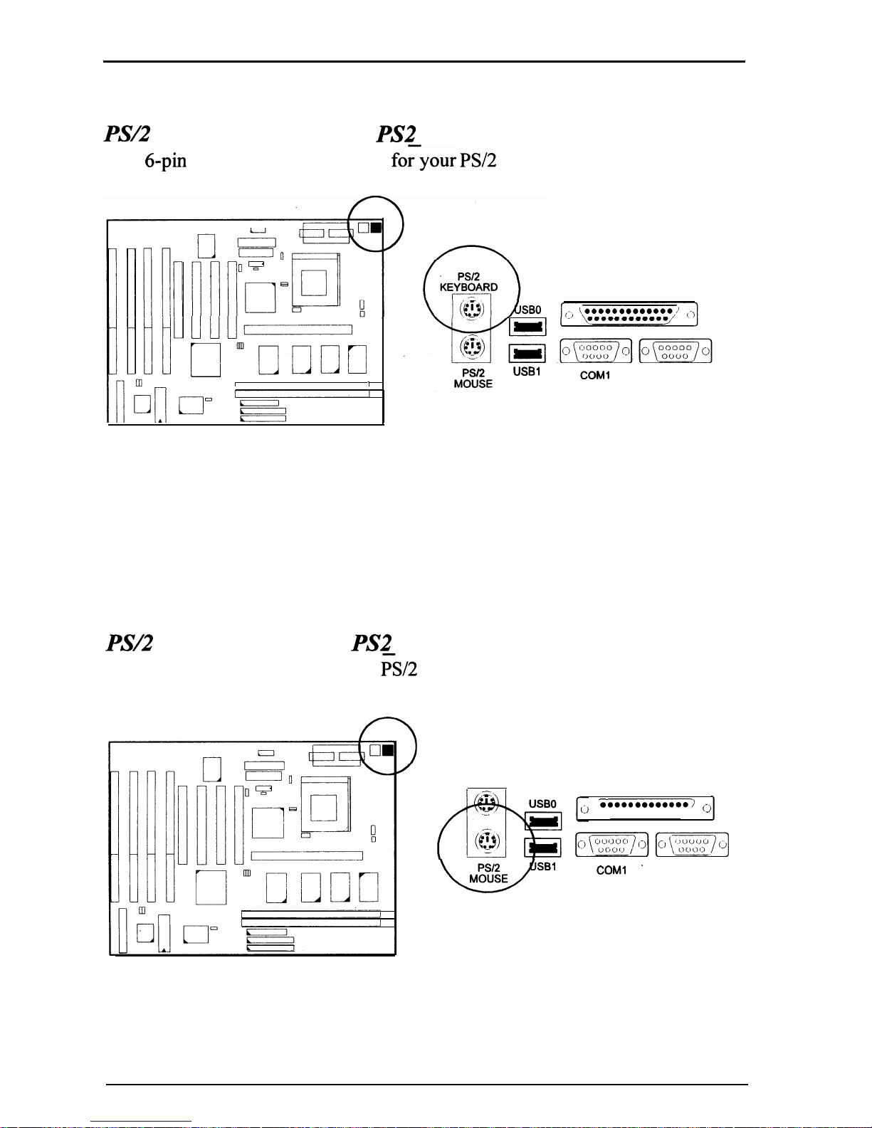
PS/2 Keyboard Connector: PS2 KB
This
6-pin
female connector is used
foryour PS/2
keyboard.
Llu__l-
l----l’“cooc
I
1
hfl~%E
USBl
PSI’2
Mouse Connector: PS2 MS
This connector is connected to the
i%/2
mouse.
PSI2
KEYBOARD
WSB1
PRINTER
COMl
COM2
PRINTER
l
oooooooooooo~
l
ooooooooooo
(-,
-
[_I[_]
COMl
.
COM2
38
Page 44
Installation Procedures
AlX
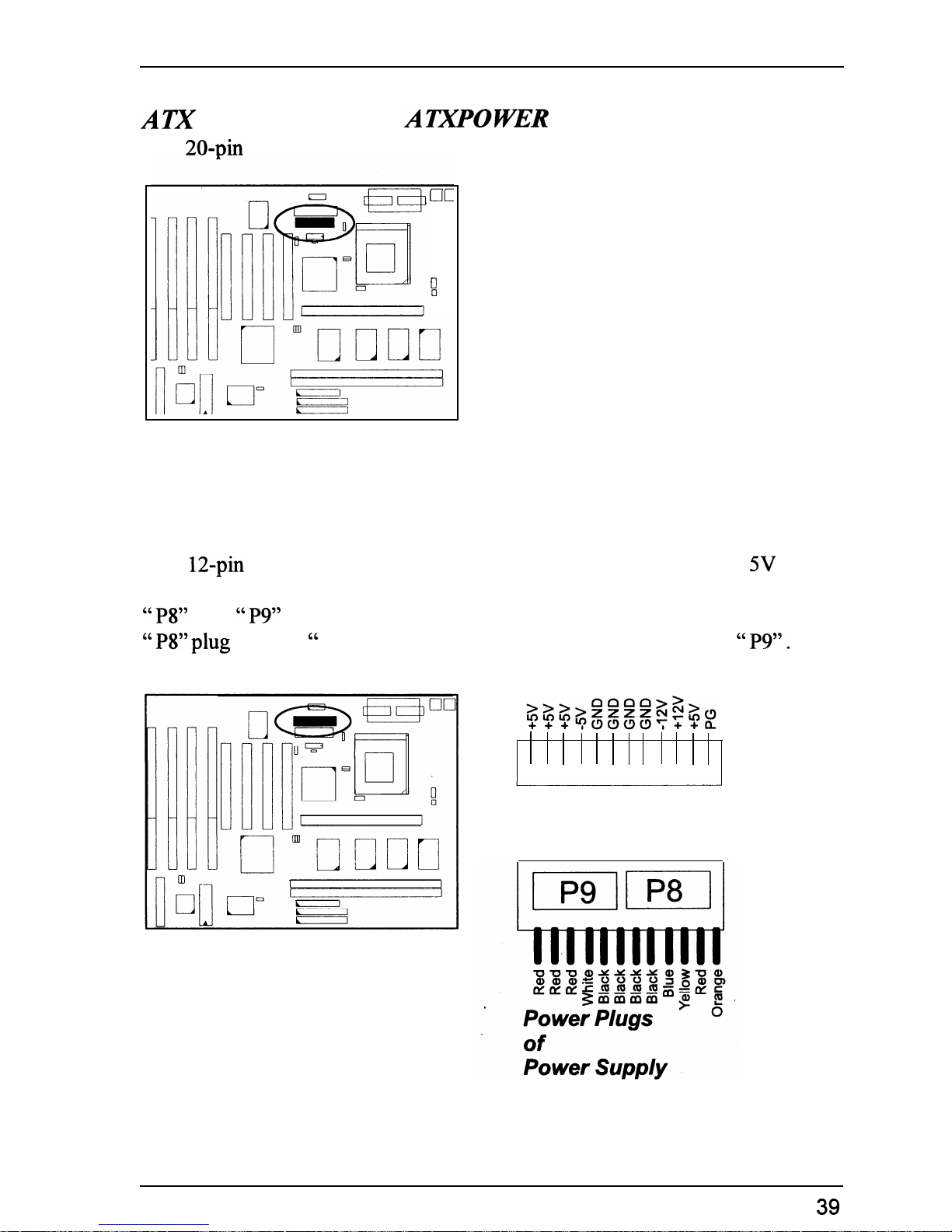
Power Connector:
AIXPOWER
This 20.pin male block connector is connected to the ATX power supply.
UL
II
cl
Standard Power Connector: POWER
This 12.pin block connector is used for connecting to the standard 5V power
supply. In the picture below, notice that, in most cases, there are two marks
“P8”
and
“P9”
on the surface of the connector. You have to insert the
“
P8”plug into the “ P8” section of the connector, and so forth for “ P9”. Two
black wires must be in the middle.
Power
Connector
39
Page 45
PT-2010 Mainboard Manual
IDE
-HDD
Device Connector:
PmM4RY
and SECONDARY
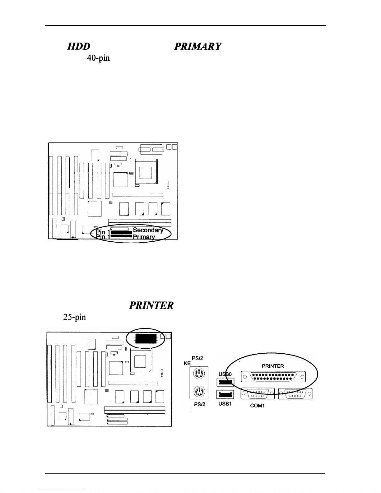
These two 40.pin block connectors are used for your IDE hard disks. It you
have one IDE hard disk, connect it to the PRIMARY connector using the IDE
HDD flat cable provided with the mainboard. The BIOS auto detection sets it to
be a “Primary Master” disk. If you want to install another IDE hard disk or
CD-ROM, please use the SECONDARY connector. If two hard disks are
connected to the PRIMARY connector using the same cable, one of them is the
master drive, the other one is the slave drive. You may need to set jumpers for
the slave drive; please refer to the HDD manual for details.
e
Printer Connector: PRINTER
This
25pin
D-Sub female connector is attached to your printer.
PSI2
YBOARD
PSI2
USBl
MOUSE
COMl
COM2
40
Page 46
Installation Procedures
Remote Power Supply Connector: RPW CON
-
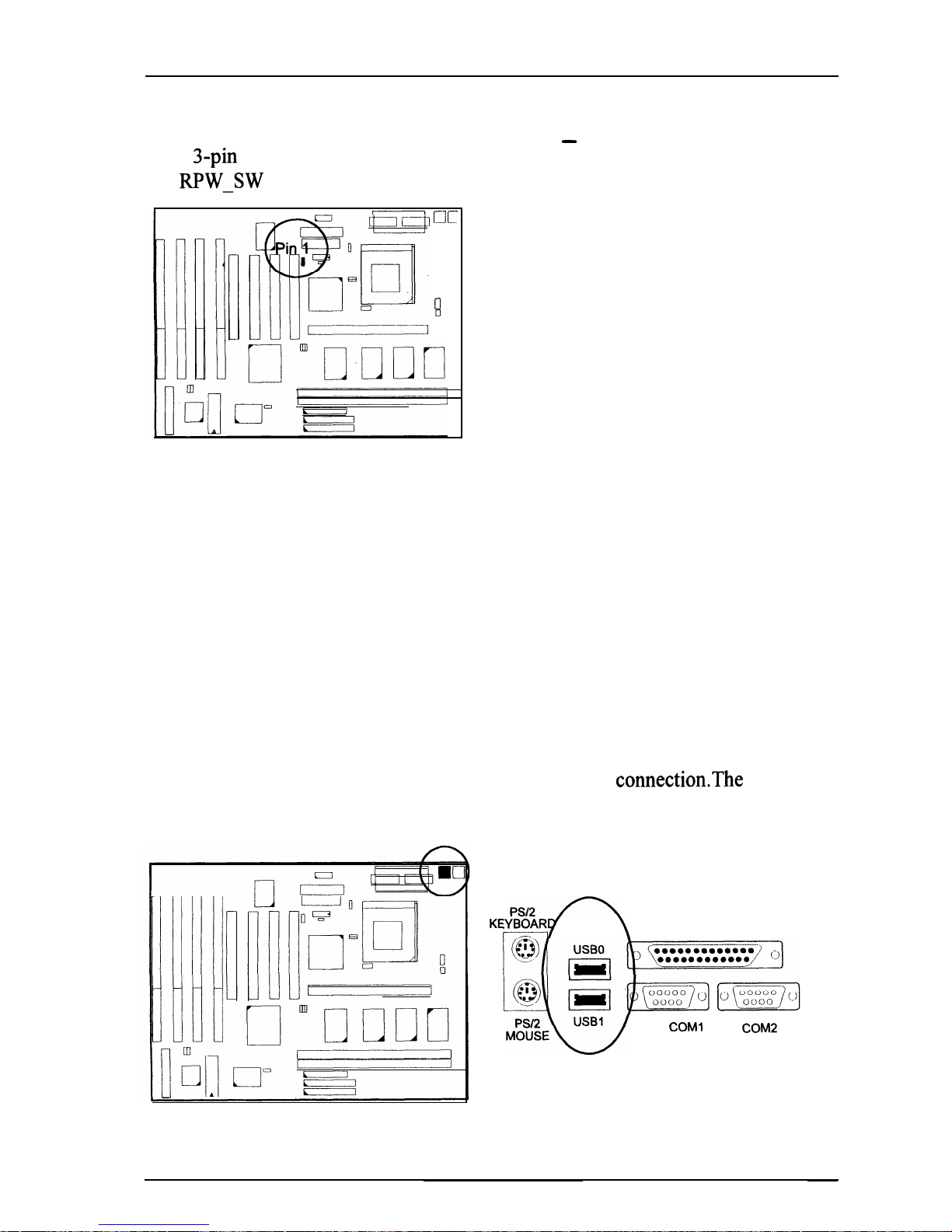
This
3-pin
male connector allows you to enable or disable the system power if
the
RPW_SW
is on or off.
,,
-_-
UL
0
II
Universal Serial Bus Connectors
These two connectors are reserved for future upgrade for linking with the
peripherals devices that support Universal Serial Bus connectionThe connector
pinheads are not installed on this mainboard currently.
KEYBOAR
r-7-f
\
PRINTER
M;;EEw
COMl
COW
41
Page 47
Award BIOS Setup
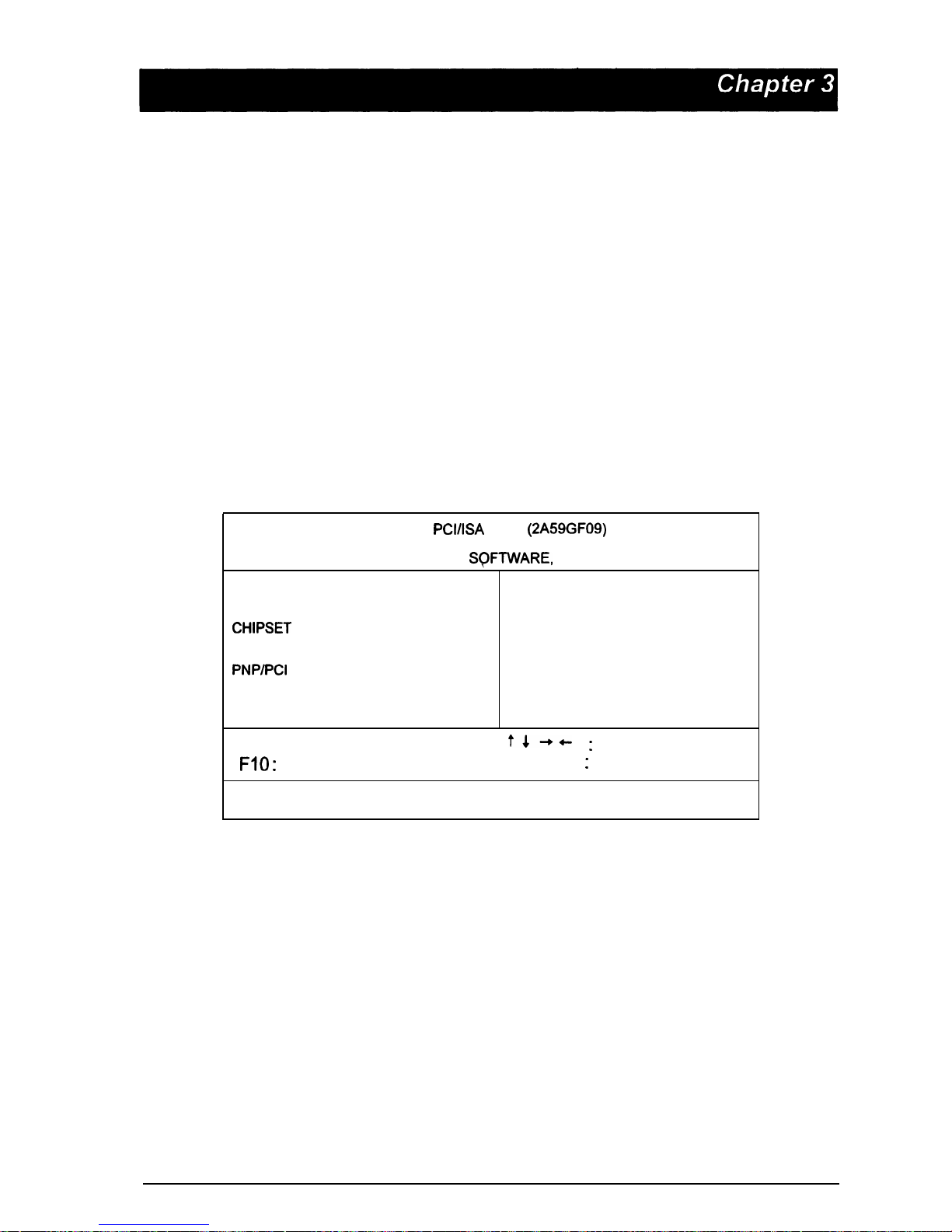
The mainboard comes with the Award BIOS chip that contains the ROM Setup
information of your system. This chip serves as an interface between the
processor and the rest of the mainboard’s components. This chapter explains the
information contained in the Setup program and tells you how to modify the
settings according to your system configuration.
CMOS Setup Utility
ROM
PCI/ISA
BIOS
(2A59GF09)
CMOS SETUP UTILITY
AWARD
SQFTWARE,
INC.
STANDARD CMOS SETUP
INTEGRATED PERIPHERALS
BIOS FEATURES SETUP
SUPERVISOR PASSWORD
CHIPSET
FEATURES SETUP
USER PASSWORD
POWER MANAGEMENT SETUP
IDE HDD AUTO DETECTION
PNP/PCI
CONFIGURATION
SAVE & EXIT SETUP
LOAD BIOS DEFAULTS
EXIT WITHOUT SAVING
LOAD SETUP DEFAULTS
ESC : Quit
t4-t
:
Select Item
FIO
:
Save & Exit Setup
(Shift) F2 : Change Color
Time, Date, Hard Disk Type...
A Setup program, built into the system BIOS, is stored in the CMOS RAM. This
Setup utility program allows changes to the mainboard configuration settings. It
is executed when the user changes system configuration; user changes system
backup battery; or the system detects a configuration error and asks the user to
run the Setup program. Use the arrow keys to select and press Enter to run the
selected program.
43
Page 48
PT-2010 Mainboard Manual
Standard CMOS Setup
ROM PCVISA BIOS
STANDARD CM0
&
2A59GF09)
SETUP
AWARD SOFTWARE, INC.
Date (mm:dd:yy) : Mon, Jan 24 1994
Time (hh:mm:ss)
: 15 :
38
: 55
HARD DISKS
TYPE SIZE CYLS HEAD PRECOMP LANDZ SECTOR MODE
Primary Master
:
User 541
1409
16
65535 1408
63
Normal
Primarv Slave
:
None
0 0
0
0 0
’
0
______
Secondary Master : None
_
Secondary Slave : None
:
:
00
!
0
0
; ::::::
Drive A :
1.44M,
3.5 in.
Drive B :
1.2M,
5.25 in.
Video
:
EGA/VGA
Halt On : All Errors
Base Memory:
64OK
Extended Memory: 7168K
Other Memory: 384K
Total Memory: 8192K
ESC : Quit
Fl: Help
t 4 -,
6
:
Select Item
(Shift)FZ
:
Change Color
PU/PD/+/-
:
Modify
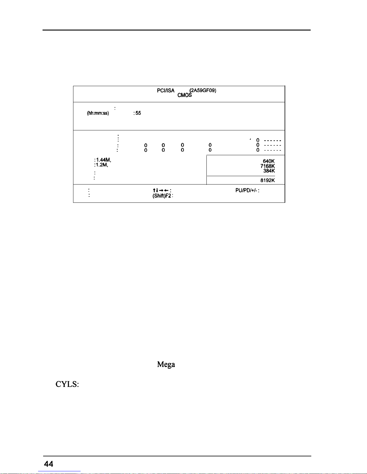
The Standard CMOS Setup screen is displayed above. Each item may have one
or more option settings. The system BIOS automatically detects memory size,
thus no changes are necessary. Use the arrow keys to highlight the item and then
use the PgUp or PgDn keys to select the value you want in each item.
Hard Disk Configurations
TYPE:
Select from 1 to 45 to fill remaining fields with
drives. Select User to fill the remaining fields.
HDD type automatically.’
SIZE:
The hard disk size. The unit is
Mega
Bytes.
CYLS:
The cylinder number of the hard disk.
HEAD:
predefined values of disk
Select Auto to detect the
The read/write head number of hard disk. The range is from 1 to 16.
Page 49

Award BIOS Setup
PRECOMP:
The cylinder number at which the disk drive changes the write timing.
LANDZ:
The cylinder number that the disk drive heads (read/write) are seated when
the disk drive is parked.
SECTOR:
The sector number of each track defined on the hard disk. The range is from
1 to 64.
MODE:
’
Select Auto to detect the mode type automatically. If your hard disk
supports the LBA mode,‘ select LBA or Large. However, if your hard disk
cyclinder
is more than 1024 and does not support the LBA function, you
have to set at Large.
Select Normal if your hard disk supporting cylinders is below 1024.
Software Turbo Speed
The BIOS supports Software Turbo Speed feature. Instead of pressing the
Turbo Speed Button on the front panel, simply press the Alt, Ctrl, and +
keys at the same time to enable the Turbo Speed feature; and press the
Alt,
Ctrl, and
-
keys at the same time to disable the feature.
45
Page 50
PT-2010 Mainboard Manual
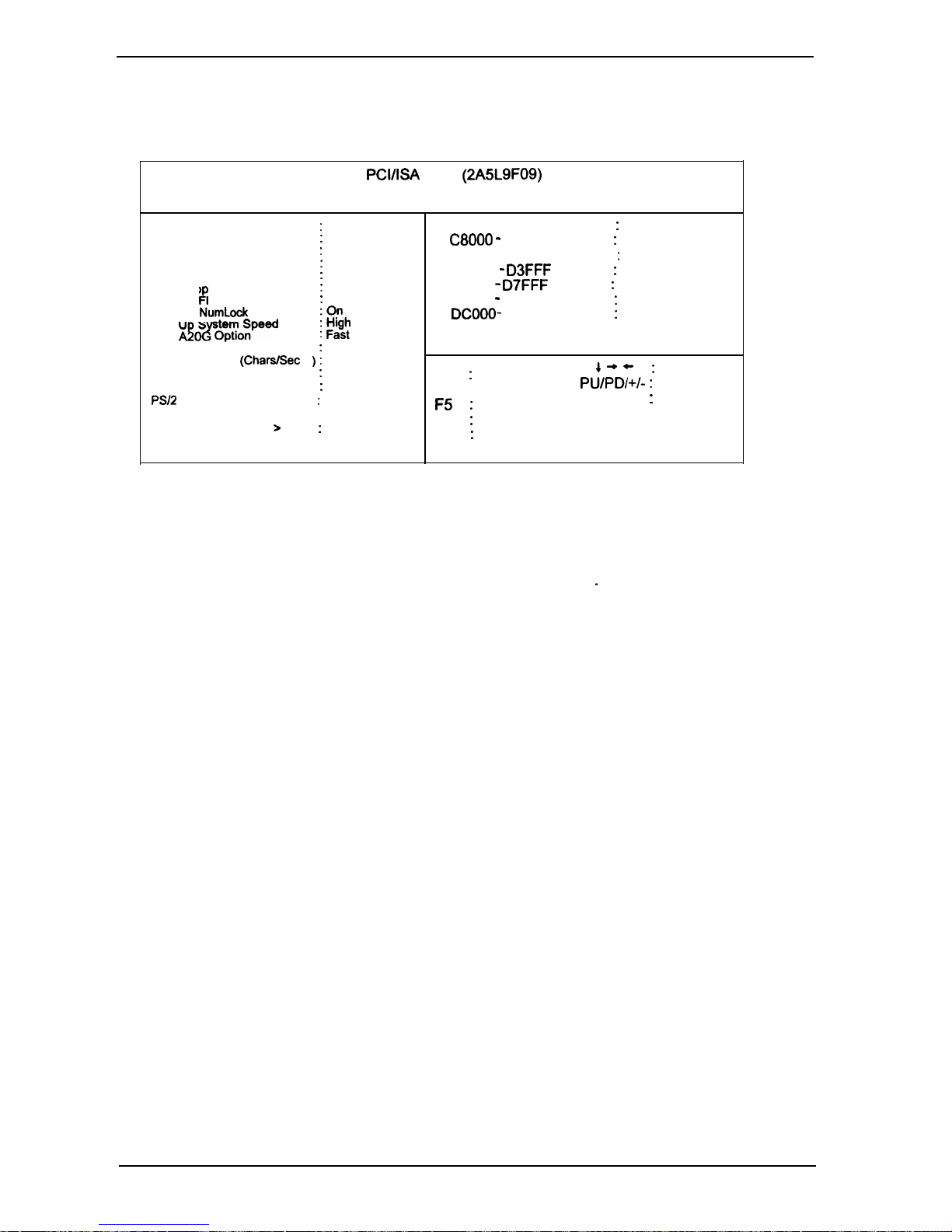
BIOS Features Setup
Virus
Warning
CPU Internal Cache
External Cache
Quick Power On Self Test
Boot Sequence
Swap Flo
Fp
py Drive
Boot Up loppy Seek
Boot Up
NumLock
Status
Boot U S
&epTo;peed
Gate
A!%
ROM PCI/ISA BIOS
(2A5L9F09)
BIOS FEATJRES SETUP
AWARD SOFTWARE. INC.
:
Disabled
Video BIOS Shadow : Enabled
:
Enabled
C8000 - CBFFF Shadow : Disabled
:
Enabled
:
Disabled
CCOOO- CFFFF Shadow : Disabled
:
A, C
DO000 - D3FFF Shadow : Disabled
:
Disabled
04000
-
D7FFF
Shadow : Disabled
:
Enabled
08000 - DBFFF Shadow : Disabled
+-I
i F;$
DCOOO-
DFFFF Shadow : Disabled
Typematic Rate Setting
:
Disabled
Typematic Rate (CharsISec
) :
6
Typematic Delay (Msec)
:
250
security
option
:
Setup
PS/2 mouse function control : Enabled
OS Select For DRAM > 64MB : Non-OS2
ESC : Quit
t 4 +
+-
:
Select Item
Fl
: Help
PU/PD/+/-
:
Modify
F5
:
Old
Values
(Shift) F2 : Color
F6
:
Load BIOS Defaults
F7
:
Load Setup Defaults
Virus Warning
When enabled, assigns the BIOS to monitor the master boot sector and the
DOS boot sector of the first hard disk drive.
-
The options are: Enabled, Disabled (Default).
CPU Internal Cache
When enabled, improves the system performance. Disable this item when
testing or trouble-shooting.
The options are: Enabled (Default), Disabled.
External Cache
When enabled, supports an optional cache SRAM.
The options are: Enabled (Default), Disabled.
Quick Power On Self Test
When enabled, allows the BIOS to bypass the extensive memory test.
The options are: Enabled, Disabled (Default).
Boot Sequence
Allows the system BIOS to first try to boot the operating system from the
selected disk drive.
The options are: A, C (Default); C, A; C, CDROM, A; CDROM, C, A.
46
Page 51

Award BIOS Setup
Swap Floppy Drive
Allows you to switch the order in which the operating system accesses the
floppy drives during boot up.
The options are: Enabled, Disabled (Default)
Boot Up Floppy Seek
When enabled, assigns the BIOS to perform floppy diskette drive tests by
issuing the time-consuming seek commands.
The options are: Enabled (Default), Disabled.
Boot Up Numlock Status
When set to On, allows the BIOS to automatically enable the Num Lock
Function when the system boots up.
The options are: On (Default), Off.
Boot Up System Speed
Allows you to adjust the system speed when the system boots up.
The options are: High (Default), Low.
Gate A20 Option
When set at Fast, allows a faster access response under Protected mode.
The options are: Fast (Default), Normal.
Typematic Rate Setting
The term typematic means that when a keyboard key is held down, the
character is repeatedly entered until the key is released. When this item is
enabled, you may change the typematic repeat rate.
The options are: Disabled (Default), Enabled.
Typematic Rate
(Chars/Set)
Sets the rate of a character repeat when the key is held down.
The options are: 6 (Default), 8, 10, 12,
15,20,24,
30.
Typematic Delay (Msec)
Sets the delay time before a character is repeated.
The options are: 250 (Default), 500, 750, 1000 millisecond.
Security Option
L
Allows you to set the security level of the system.
The options are: Setup (Default), System.
*
47
Page 52
PT-2010 Mainboard Manual
PS/2
Mouse Function Control
When enabled, allows you to release IRQ 12 for using the
PS/2
mouse.
The options are: Enabled (Default), Disabled.
OS Select For DRAM 64MB
If your operating system (OS) is OS2, select the option OS2. Otherwise, stay
with the default setting Non-OS2.
The options are: Non-OS2 (Default), OS2.
Video BIOS Shadow
Allows the BIOS to copy the video ROM code of the add-on video card to
the system memory for faster access.
The options are: Enabled (Default), Disabled.
C8000-CBFFF to DCOOO-DFFFF Shadow
.
Allows the BIOS to copy the BIOS ROM code of the add-on card to system
memory for faster access. It may improve the performance of the add-on
card.
Some add-on cards will not function properly if its BIOS ROM code is
shadowed. To use these options correctly, you need to know the memory
address range used by the BIOS ROM of each add-on card.
The options are: Enabled, Disabled (Default).
48
.
Page 53
,
Award BIOS Setup
Chipset
Features Setup
Auto Configuration
DRAM Timrng
ROM PCI/ISA BIOS ZA59GFb9)
CHIPSET FEATUR&S SETUP
AWARD SOFTWARE, INC.
:
Enabled
:
60 ns
Delayed PCI Transaction : Disabled
Fast RAS To CAS Delay
:3
DRAM Read Burst EDO/FP)
4-
:
x2221x333
DRAM Write Burst
rmin
Fast MA to RAS# Delay!!LK
:
x222
Fast
ED0
Path Select
:2
:
Enabled
Refresh
RAS#
Assertion
* 5
Clks
SDRAM (CAS
LaVRAS-to-CAS)
I
3)3/5/8
System BIOS Cacheable
:
Disabled
Video BIOS Cacheable
i Fabled
8 Bit
i/O
Recovery Time
16 Bit
I/O
RecoveYTime
:1
Memory Hole At 1 M-16M
:
Disabled
Peer Concurrency
:
Enabled
ESC : Quit
tJ4+
:
Select Item
PU/PD/+/-
:
Modify
Fl
: Help
F5
: Old Values
(Shift)
F2
:
Color
F6
: Load BIOS Defaults
F7: Load Setup Defaults
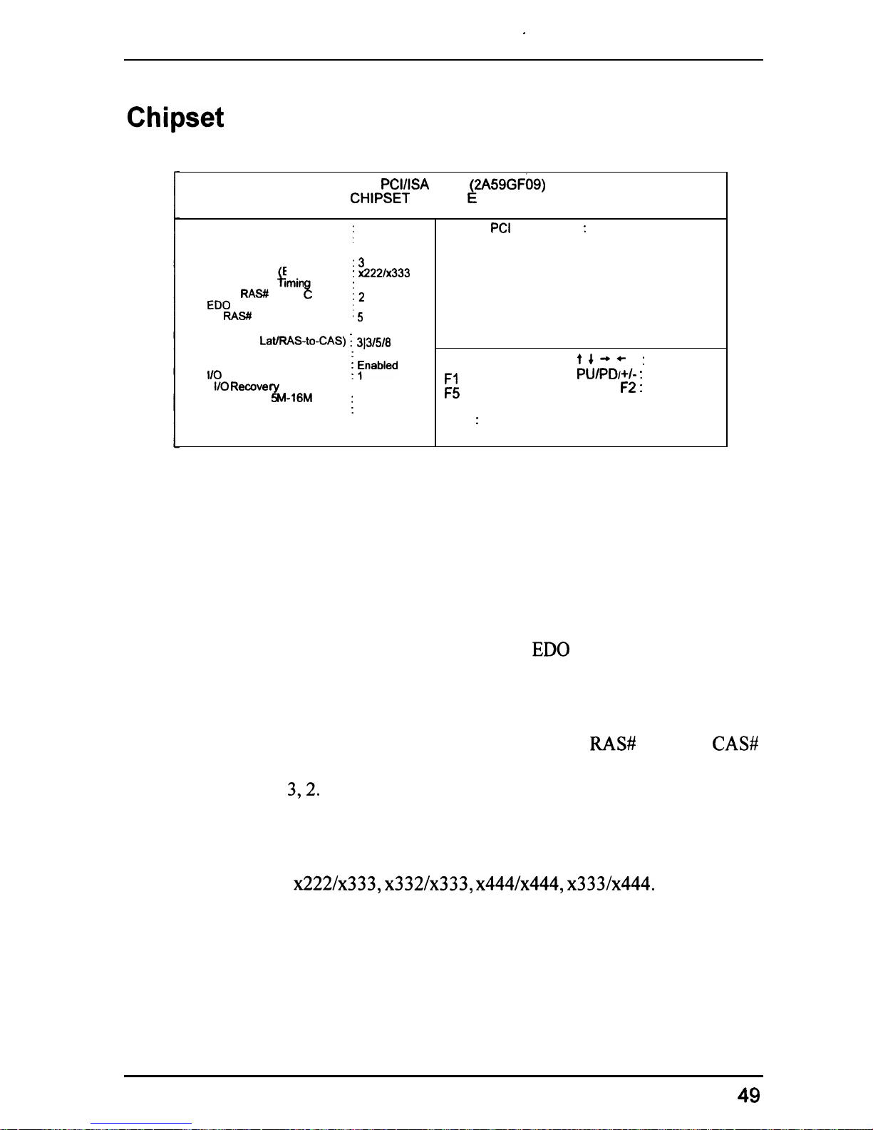
Auto Configuration
When set at Enabled, it allows you to configure the features that from the
third one, Fast RAS To CAS Delay, to the eighth one, Refresh RAS#
Assertion.
The options are: Enabled (Default), Disabled.
DRAM Timing
Allows you to select the speed of data access to ED0 DRAM.
The options are: 60 ns (Default), 70 ns.
Fast RAS To CAS Delay
Allows you to define the delay time that from DRAM
RAW
active to
CAS#
active.
The options are: 3,2. Unit: Clock T.
DRAM Read Burst (EDO/FP)
Allows you to define DRAM read burst timing.
The options are:
x222/x333, x3321x333, x444/x444, x3331x444.
DRAM Write Burst Timing
Allows you to define DRAM write burst timing.
The options are: X-3-3-3, X-2-2-2, X-4-4-4.
49
Page 54
PT-2010 Mainboard Manual
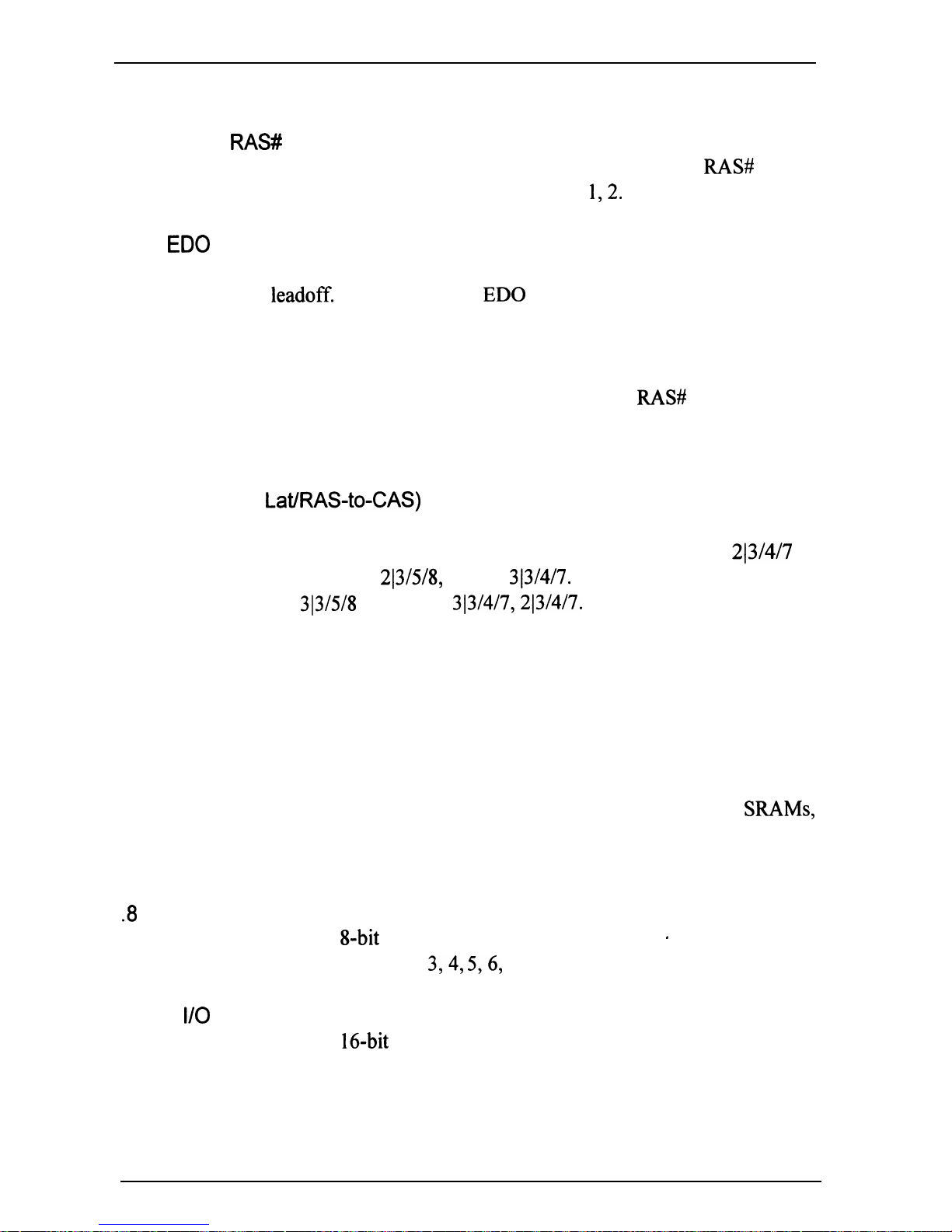
Fast MA to RAW Delay CLK
Allows you to select the clock of the memory address (MA) to
RAW
delay.
This feature is for technician use. The options are:
1,2.
Fast ED0 Path Select
When enabled, it allows you to select a fast path for CPU to DRAM read
cycles for the
leadoff.
This is valid for ED0 DRAMS only.
The options are: Disabled, Enabled.
Refresh RAS# Aassertion
This feature allows you to control the number of clocks
RAS#
is asserted for
Refresh cycles.
The options are: 4 Clks, 5 Clks.
SDRAM (CAS
LatlRAS-to-CAS)
If you install a DIMM, this feature allows you to select the ratio of CAS
Latency to RAS-to-CAS. The default setting is slowest. The
213/4/7
is
fastest. The second one is
213/S/8,
then is
313/4/7.
The options are:
3(3/5/8
(Default),
313/4/7,213/4/7.
System BIOS Cacheable
When enabled, allows the ROM area FOOOOH-FFFFFH to be cacheable
when cache controller is activated.
The options are: Disabled (Default), Enabled.
Video BIOS Cacheable
When enabled, allows the system to use the video BIOS codes from
SRAMs,
instead of the slower DRAMS or ROMs.
The options are: Enabled (Default), Disabled.
.8
Bit I/O Recovery Time
Allows you to set the
8-bit
ISA I/O recovery time.
.
The options are: 1 (Default), 2, 3,4, 5,6, 7, NA, 8. Unit: Bus clock.
16 Bit
I/O
Recovery Time
Allows you to set the
16-bit
ISA I/O recovery time.
The options are: 1 (Default), 2, 3, NA, 4. Unit: Bus clock.
50
Page 55
Award BIOS Setup
Memory Hole At
15M-16M
When enabled, the memory hole at the
15MB
address will be relocated to
the
15-l
6MB address range of the ISA cycle when the processor accesses
the
15-l
6MB address area.
When disabled, the memory hole at the 15MB address will be treated as a
DRAM cycle when the processor accesses the
15- 16MB
address area.
The options are: Enabled, Disabled (Default).
Peer Concurrency
Enable this item to allow the processor to continue its operation while
another
PC1
Bus is active.
The options are: Enabled (Default), Disabled.
Delay PCI Transaction
Enable this item to allow the PIIX3 chip to abort the current
PC1
master
cycle
and
to accept the new
PC1
master request; after it services the new
PC1
master request, it reaccepts the orginal
PC1
master and returns the
PC1
data
phase to the orignal
PC1
master.
This should enhance the system
performance.
.
The options are: Enabled, Disabled (Default).
51
Page 56
PT-2010 Mainboard Manual
Power Management Setup
AWARD SOFTWARE. INC.
Power Management
:
Disable
PM Control by APM
: Yes
Video Off Method
:
DPMS
MODEM Use IRQ
:
NA
Doze Mode
:
Disable
Standby Mode
:
Disable
Sus end Mode
:
Disable
HDJPower Down
:
Disable
;R$ke
Up Events In Doze & Standby l *
IRQ4
lRQ6
IRQ12
l * Power
IRQ3
LOO 2”,
Resume Events l *
IRQ4
$l;j
1:::
%!2;
)
: OFF
Floppy Disk)
:
OFF
1%:
LPT 1)
:
OFF
IRQ9
RTC Alarm)
IRQ2 Redir)
; g;;
ESC : Quit
t4-+
:
Select Item
Fl
:
Help
PUIPD/+/-
:
Modify
E
: Old Values (Shift) F2 : Color
:
Load BIOS Defaults
F7
: LOad Setup
Defaults
.
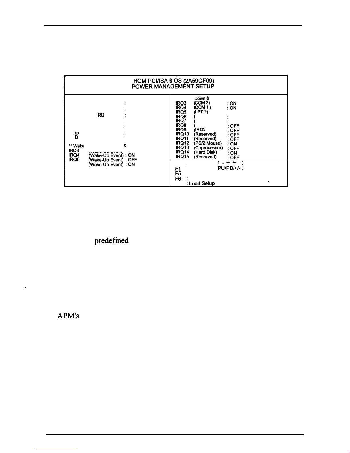
Power Management
This item allows you to adjust the power management features. Select
Disable for disabling global power management features. Select User
Defined for configuring your own power management features. MIN Saving
initiates all predefined timers in their minimum values. MAX Saving, on the
other hand, initiates maximum values.
The options are:
Disable (Default), User Defined, MIN Saving, MAX
Saving.
,
PM Control by APM
The option No allows the BIOS to ignore the APM (Advanced Power
Management) specification. Selecting Yes will allow the BIOS wait for
APM’s
prompt before it enters Doze mode, Standby mode, or Suspend
mode.
If the APM is installed, it will prompt the BIOS to set the system into power
saving mode when all tasks are done.
The options are: No, Yes (Default).
52
Page 57
Award BIOS Setup
Video Off Method
The option V/H SYNC+Blank allows the BIOS to blank off screen display
by turning off the V-Sync and H-Sync signals sent from add-on VGA card.
DPMS Supported allows the BIOS to blank off screen display by your
add-
on VGA card which supports DPMS (Display Power Management Signaling
function). Blank Screen allows the BIOS to blank off screen display by
turning off the red-green-blue signals.
The options are:
V/H
SYNC+Blank, DPMS (Default), Blank Screen.
MODEM Use
IRQ
This feature allows you to select the
IRQ#
of the system that is the same
IRQ#
as the modem use.
The options are: NA (Default), 3, 4, 5, 7, 9, 10, 11.
Doze Mode
When disabled, the system will. not enter Doze mode. The specified time
option defines the idle time the system takes before it enters Doze mode.
The options are: Disabled(Default),
1,2,4,6,
8,
10,20,
30,40 Min, 1 Hr.
Standby Mode
When disabled, the system will not enter the Standby mode. The specified
time option defines the idle time the system takes before it enters Standby
mode.
The options are: Disabled (Default),
1,2,4,6,
8,
10,20,
30,40 Min, 1 Hr.
Suspend Mode
When disabled, the system will not enter Suspend mode. The specified time
option defines the idle time the system takes before it enters Suspend mode.
The options are: Disabled (Default),
1,2,4,
6, 8,
10,20,
30,40 Min, 1 Hr.
53
Page 58
PT-2010 Mainboard Manual
HDD Power Down
Selecting Disable will not turn off the hard disk drive (HDD) motor.
Selecting 1 Min.. 15 Min allows you define the HDD idle time before the
HDD enters the Power Saving Mode. The option When Suspend lets the
BIOS turn the HDD motor off when system is in Suspend mode.
The options 1 Min.. 15 Min and When Suspend will not work concurrently.
When HDD is in the Power Saving Mode, any access to the HDD will wake
the HDD up.
The options are: Disable (Default), 1 Min.. 15 Min, When Suspend.
IRQ3,4,8, 12 (Wake-Up Event)
Selecting OFF allows the BIOS to refrain from waking up the system.
Selecting ON allows the BIOS to wake up the system
from
Doze mode,
Standby mode, or Suspend mode.
The options are: OFF, ON.
The default of
IRQ3,,
4, 12 (Wake-Up Event): ON.
The default of
IRQ8
(Wake-Up Event): OFF.
Power Down Activities / IRQ3 - IRQl5
Selecting ON will enable the power management timers when a no activity
event is detected in the specified I/O port or component.
Selecting OFF will disable the PM timer even if a no activity event is
detected.
The options are: ON, OFF.
The default value of IRQ3
(COM2),
IRQ4 (COMl), IRQ12
(PS/2
Mouse),
’
IRQ14 (Hard Disk) : ON.
The default setting of other
IRQs: OFF.
’
.
54
Page 59
Award BIOS Setup
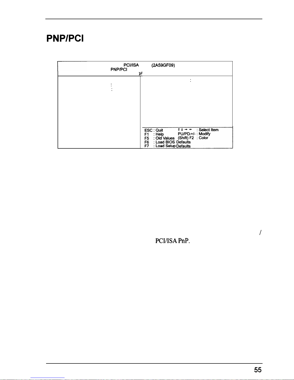
PNP/PCl
Configuration Setup
ROM
PCVISA
BIOS
(2A59GF09)
PNP/PCI
CONFIGURATION
AWARD SC
PNP OS Installed
: No
Resource Controlled By : Auto
Reset Configuration Data : Disabled
TWARE. INC.
PCI IRQ Actived By: Level
PNP OS Installed
If your operating system is a Plug-and-Play one, such as Windows 95, select
Yes.
The options are: No (Default), Yes.
Resources Controlled By
If you set at Auto, the BIOS automatically arranges all system resources for
you. If there exists conflict or you are not satisfy with the configuration,
simply set all the resources listed in the above figure by selecting Manual.
The options are: Auto (default), Manual. The manual options of IRQ-
/
DMA- assigned to are: Legacy ISA,
PCI/ISA PnP.
Reset Configuration Data
When enabled, allows the system to clear the last BIOS configuration data
and reset them with the default BIOS configuration data.
The options are: Enabled, Disabled (default).
PCI IRQ Actived By
We suggest that you set this to its default configuration unless you are a
qualified technician.
The options are: Level (Default), Edge.
55
Page 60
PT.201
0 Mainboard Manual
Load BIOS Defaults
BIOS defaults contain the most appropriate values of the system parameters that
allow minimum system performance. The OEM manufacturer may change the
defaults through MODBIN before the binary image bums into the ROM.
Load Setup Defaults
Selecting this field loads the factory defaults for BIOS and Chipset Features
which the system automatically detects.
m
56
Page 61
Award BIOS Setup
Integrated Peripherals
.
IDE HOD Block Mode
IDE Primary Master
PI0
IDE Primary Slave
PI0
IDE Secondary Master
PI0
IDE Secondary Slave
PI0
On-Chip Primary
On-Chip Secondary F$ !EE
USB Controller
Onboard FDD Controller
Onboard
Serial Port 1
Onboard Serial Port 2
UART 2 Mode
Onboard Parallel
Port
Onboard Parallel Mode
ROM
PCVISA
BIOS
(2A59GFOQ)
INTEGRATED PERIPHERALS
: 378H/IRQ7
ESC : Quit
:
SPP
Fl
:
Hela
14-c
: Select Item
PU/PDI+/-
:
Modifv
. .
E
i bCbrvalues
(Shift) F2 : Color-
: Load BIOS Defaults
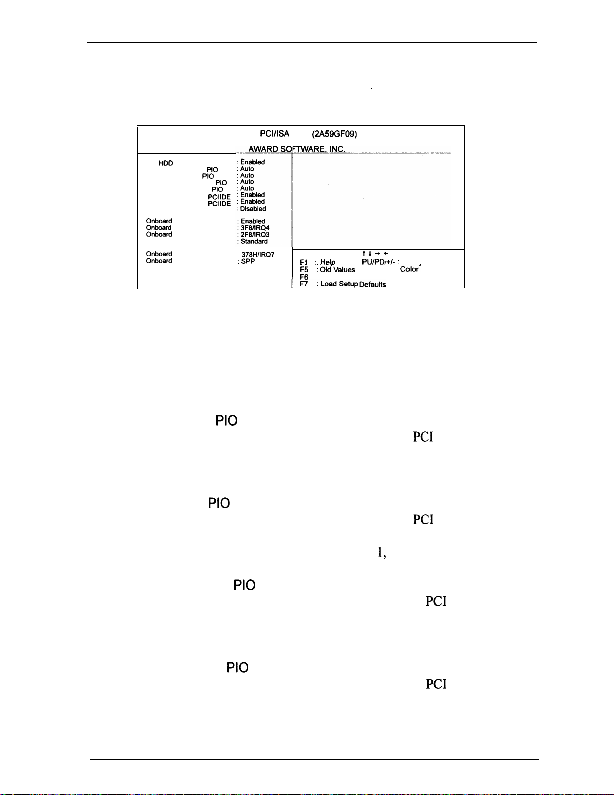
IDE HDD Block Mode
When enabled, allows the system to execute read/write requests to hard disk
in block mode.
The options are: Enabled (Default), Disabled.
IDE Primary Master PI0
Allows an automatic or a manual configuration of the
PC1
primary IDE hard
disk (master) mode.
The options are: Auto (Default), Mode 0, Mode 1, Mode 2, Mode 3, Mode 4.
IDE Primary Slave PI0
Allows an automatic or a manual configuration of the
PC1
primary IDE hard
disk (slave) mode.
The options are: Auto (Default), Mode 0, Mode 1, Mode 2, Mode 3, Mode 4.
IDE Secondary Master PI0
Allows an automatic or a manual configuration of the
PC1
secondary IDE
hard disk (master) mode.
The options are: Auto (Default), Mode 0, Mode 1, Mode 2, Mode 3, Mode 4.
IDE Secondary Slave PI0
Allows an automatic or a manual configuration of the
PC1
secondary IDE
hard disk (slave) mode.
The options are: Auto (Default), Mode 0, Mode 1, Mode 2, Mode 3, Mode 4.
57
Page 62
PT-2010 Mainboard Manual
On-Chip Primary PCI IDE
When enabled, allows you to use the
onboard
primary
PC1
IDE.
The options are: Enabled (Default), Disabled.
On-Chip Secondary PCI IDE
When enabled, allows you to use the
onboard
secondary
PC1
IDE.
The options are: Enabled (Default), Disabled.
USB Controller
If you do not use the
onboard
USB feature, it allows you to disable it.
The options are: Enabled, Disabled (Default).
Onboard
FDD Controller
When enabled, the floppy diskette drive (FDD) controller is activated.
The options are: Enabled (Default), Disabled.
. Onboard Serial Port 1
If the serial port 1 uses the
onboard
I/O controller, you can modify your
,
serial port parameters. If an I/O card needs to be installed, COM3 and
COM4 may be needed.
The options are:
3FWIRQ4
(Default),
2FWIRQ3, 3EWIRQ4, 2EWIRQ3,
Disabled,
3F8/IRQ 11,2F8/IRQ
10,
3E8/IRQ 11,2E8/IRQ
10.
Onboard
Serial Port 2
If the serial port 2 uses the
onboard I/O
controller, you can modify your
serial port parameters. If an I/O card needs to be installed, COM3 and
COM4 may be needed.
The options are:
2F8/IRQ3
(Default),
3E8/IRQ4, 2E8/IRQ3,
Disabled,
3F8lIRQ
11,2FS/IRQ
10,3E8/IRQ 11,2E8/IRQ
10,
3F8lIRQ4.
UART 2 Mode
Allows you to select the IR modes if the serial port 2 is used as an IR port.
Set at Standard, if you use COM2 as the serial port as the serial port, instead
as an IR port.
The options‘are: HPSIR, ASKIR, Standard (Default).
IR
Function Duplex
This feature allows you to select the infrared data transaction way.
The options are: Half (Default), Full.
58
Page 63
Award BIOS Setup
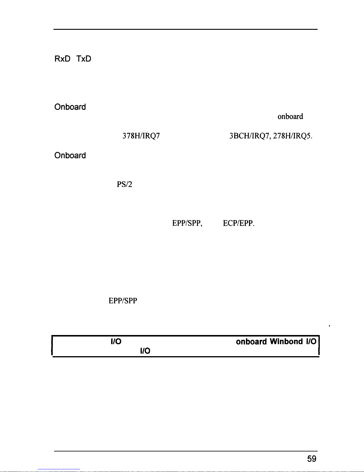
RxD
, TxD Active
The feature allows you to select the active signals of the reception end and
the transmission end. This is for technician use only.
The options are: Hi, Hi (Default); Hi, Lo; Lo, HI; Lo, Lo.
Onboard
Parallel Port
Select from a given set of parameters if the parallel port uses the
onboard
I/O
controller.
The options are:
378H/IRQ7
(Default), Disabled,
3BCH/IRQ7,278H/IRQ5.
Onboard
Parallel Mode
Allows you to connect with an advanced printer. Select SPP for standard
parallel port (SPP) used on IBM PC/XT, PC/AT and bi-directional parallel
port found on
PS/2
system. Select Extended for extended parallel port.
Select EPP Mode for enhanced parallel port. Select ECP Mode for Microsoft
and HP Extended Capabilities Parallel Port. Select ECP+EPP Mode for both
ECP and EPP Modes ports.
The options are: SPP (Default),
EPPSPP,
ECP,
ECP/EPP.
ECP Mode Use DMA
If your select ECP mode to be the parallel port mode, this feature allows you
to select Direct Memory Access (DMA) channel.
The options are: 3 (Default), 1.
Parallel Port EPP Type
If you select
EPP/SPP
mode to be the parallel port mode, this feature allows
you to select the EPP type version.
The options are: EPPl.9 (Default), EPPl.7.
s
I
IMPORTANT :
I/O
port 240h is resewed for the
onboard
chip. Devices requiring
l/O
port address should not use port 240h.
59
Page 64

PT-2010 Mainboard Manual
Supervisor/User Password
To enable the Supervisor/User passwords, select the item from the Standard
CMOS Setup. You will be prompted to create your own password. Type
your password up to eight characters and press Enter. You will be asked to
confirm the password. Type the password again and press Enter. You may
also press Esc to abort the selection and not enter a password. To disable
password, press Enter when you are prompted to enter password. A message
appears, confirming the password is disabled.
Under the BIOS Feature Setup (refer to page 46) if System is selected under
the Security Option field and the Supervisor Password is enabled, you Will
be prompted for the Supervisor Password every time you try to enter the
CMOS Setup Utility. If System is selected and the User Password is enabled,
you will be requested to enter the User Password every time you reboot the
system. If Setup is selected under the Security Option field and the User
Password is enabled, you will be prompted only when you reboot the
system.
60
Page 65
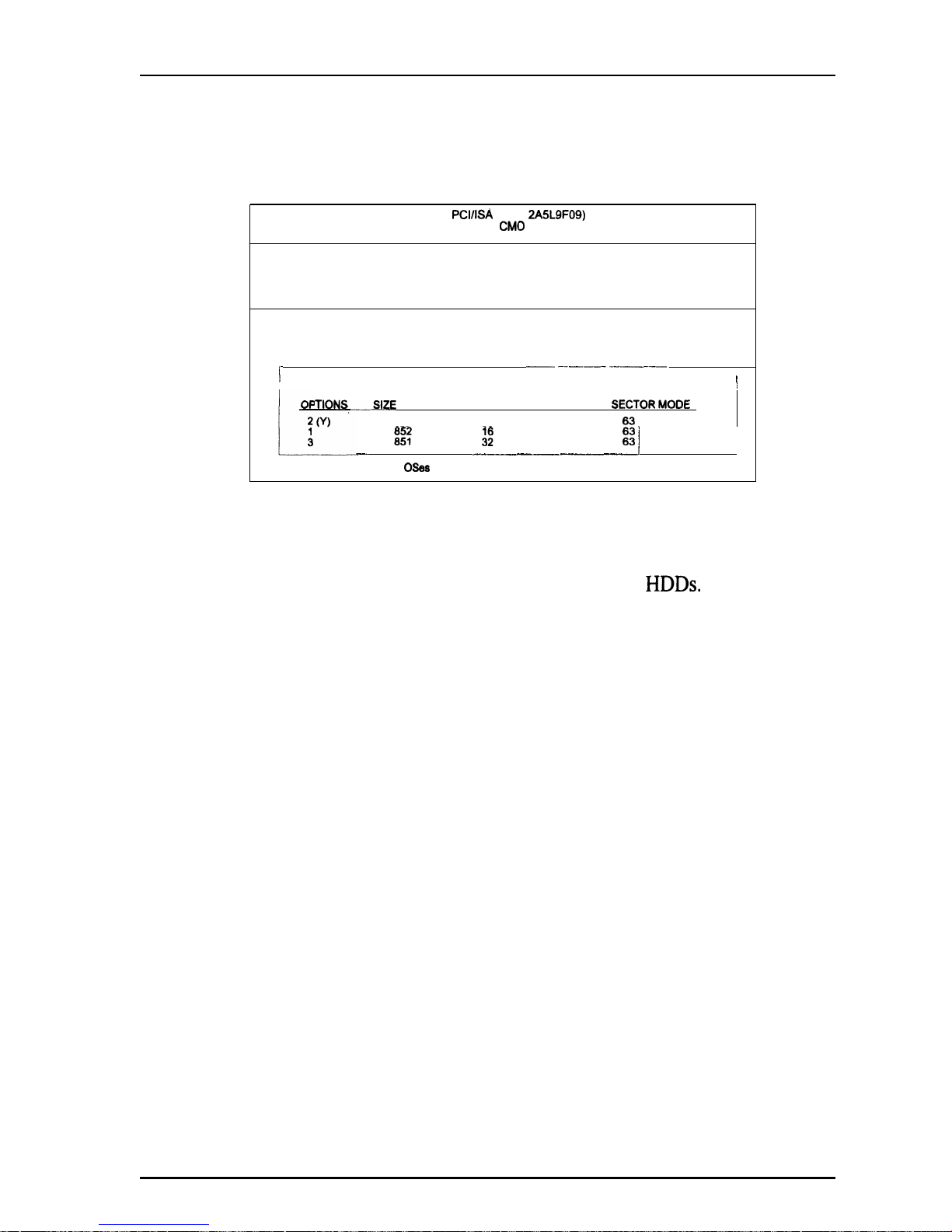
Award BIOS Setup
IDE HDD Auto Detection
ROM
PCI/ISA
BIOS
2A5L9FO9)
STANDARD
CM06SETUP
AWARD SOFTWARE, INC.
HARD DISKS
TYPE SIZE CYLS HEAD PRECOMP LANDZ SECTOR MODE
Primary Master
r
__ ---__ -____
/
I
Select Primary Master Option (N=Skip) : N
!
TIONS
-SIZE
CYLS HEAD PRECOMP LANDZ SFCTOR MODF
851
825
32
0
1850
8e::
1851 825
it
65535 65535 1650 1650
I
NORR
-
_-_______--___
j
Note : Some OSes (like SCO-UNIX) must use “NORMAL” for installation
The IDE Hard Disk Drive Auto Detection feature automatically configures
your new hard disk. Use it for a quick configuration of new hard drives. This
feature allows you to set the parameters of up to four IDE
HDDs.
The option
with (Y) are recommended by the system BIOS. You may also keys in your
own parameters instead of setting by the system BIOS. After all settings,
press Esc key to to return the main menu. For confirmation, enter the
Standard CMOS Setup feature.
61
Page 66
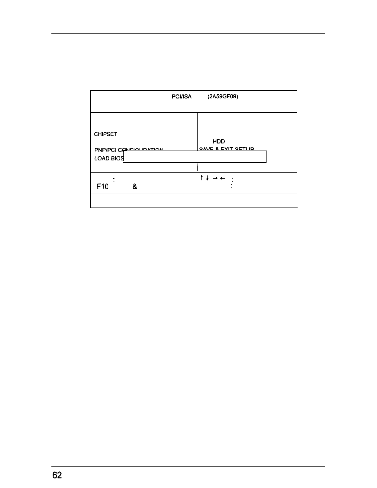
PT-2010 Mainboard Manual
Save and Exit Setup
ROM
PCI/ISA
BIOS
(2A59GF09)
CMOS SETUP UTILITY
AWARD SOFTWARE, INC.
STANDARD CMOS SETUP
INTEGRATED PERIPHERALS
BIOS FEATURES SETUP
SUPERVISOR PASSWORD
CHIPSET
FEATURES SETUP
USER PASSWORD
POWER MANAGEMENT SETUP
IDE
HDD
AUTO DETECTION
LICIfiI
Ir)ATInLI
1
CA\/f= R FYIT CFTI IP
SAVE to CMOS and EXIT (Y/N)? Y
LOAD SETUP DEFAULTS
I
ESC : Quit
t4++
:
Select Item
FlO : Save & Exit Setup
(Shift) F2 : Change Color
SAVE DATA TO CMOS and EXIT SETUP
After you have made changes under Setup, press Esc to return to the main
menu. Move cursor to Save and Exit Setup or press F 10 and then press Y to
change the CMOS Setup. If you did not change anything, press Esc again or
move cursor to Exit Without Saving and press Y to retain the Setup settings.
The following message will appear at the center of the screen to allow you to
save data to CMOS and exit the setup utility:
SAVE to CMOS and EXIT (Y/N)?
Exit Without Saving
If you select this feature, the following message will appear at the center of
the screen to allow you to exit the setup utility without saving CMOS
modifications:
Quit Without Saving (Y/N)?
Note Default values of the various Setup items on this chapter may not
necessarily be the same ones shown on your screen.
62
 Loading...