

Page 1

PAK-2102
Rev. : NA
PRELIMINARY
MANUAL
DOC No. : NA
Date : 1, 1997
Part No. : NA
Page 2

Table of Contents
Chapter 1 Overview
Main Features ............................................................................................. 2
Chapter 2 Installation Procedures
Mainboard Layout ...................................................................................... 6
1). Set System Jumpers ............................................................................... 7
Jumpers ............................................................................................. 7
Clear Password: CPW ............................................................... 8
Flash EPROM Type Selection: EP1, EP2 ................................. 8
2). Install RAM Modules ............................................................................ 9
DRAM Memory ................................................................................ 9
RAM Module Configuration ............................................................. 10
Install SIMMs ................................................................................... 12
Remove SIMMs ................................................................................ 13
Cache Memory .................................................................................. 14
Onboard Cache RAM (256KB/512KB) ............................................ 15
Onboard Cache RAM and RAM Module Mixture (512KB/1MB) .... 16
RAM Module .................................................................................... 17
3). Install the CPUs ..................................................................................... 18
CPU External Clock (Bus) Frequency: CLK1, CLK2 ............... 20
CPU to Bus Frequency Ratio: FREQ1, FREQ2 ........................ 20
Intel Pentium CPUs ................................................................... 21
Frequency ............................................................................. 21
Voltage ................................................................................. 22
AMD-K5 CPUs ......................................................................... 23
Frequency ............................................................................. 23
Voltage ................................................................................. 24
Cyrix 6x86 CPUs ...................................................................... 25
Frequency ............................................................................. 25
Voltage ................................................................................. 26
IBM 6x86 CPUs ........................................................................ 27
Frequency ............................................................................. 27
Voltage ................................................................................. 28
Installation of Cyrix (or IBM) 6x86 CPU Fan .......................... 29
4). Install Expansion Cards ......................................................................... 30
i
Page 3

ii
PAK-2102 Mainboard Manual
5). Connect Cables and Power Supply ........................................................ 31
Audio-In Connector: CD-IN ..................................................... 31
Serial Port Connectors: COM1, COM2 .................................... 31
CPU Fan Connectors: FAN ....................................................... 32
Hardware MPEG Card Connector: FC, LPB ............................. 32
Floppy Diskette Drive Connector: FLOPPY ............................. 33
Front Panel Block Connector: F_PNL ...................................... 34
Audio and Game Connector: AUDIO&GAME ......................... 35
Infrared Connector: IR .............................................................. 35
Power Connector: POWER ....................................................... 36
IDE HDD Device Connectors:
PRIMARY and SECONDARY ................................................. 37
Printer Connector: PRINTER .................................................... 37
PS/2 Keyboard Connector: PS2_KB ......................................... 38
PS/2 Mouse Connector: PS2_MS ............................................. 38
Remote Power Connector: RPW_CON ..................................... 39
Universal Serial Bus Connector: USB1 and USB2
(Reserved For Future Upgrade) ................................................. 39
VGA Connector: VCA .............................................................. 40
VGA Subsystem ................................................................... 40
Display ................................................................................. 41
The Connector ...................................................................... 42
Wave Table Connector: WAVE ................................................ 42
Page 4

Chapter 1
Overview
Congratulations on your decision to adopt the PAK-2102 mainboard. The
mainboard combines the advanced capabilities of the VIA Apollo 580VP®
chipset with a high-performance concurrent PCI local bus architecture to provide
the ideal platform for unleashing the unsurpassed speed and power of the Intel
Pentium processor. This highly-flexible mainboard is designed to run a full range
of Intel Pentium™, Cyrix 6x86™, IBM 6x86™, and AMD-K5™ processors;
and can be easily upgraded using its 321-pin ZIF socket. The processor's
advanced performance is complemented by a second level write back Pipeline
Burst SRAM cache of up to 1MB and main memory of up to 512MB RAM. The
main memory is installed using the board's six 72-pin SIMM sockets that accept
an unrivaled choice of high-speed EDO and standard Fast Page Mode DRAM.
The PAK-2102 integrates a full set of I/O features onboard, including two 16550
UART compatible serial ports, one EPP/ECP capable parallel port, and one
Floppy Disk Drive controller. It also comes with a built-in Enhanced IDE
controller that provides convenient, high-speed PCI Bus Master connections
with up to four IDE devices, including Hard Disk and CD-ROM drives. An
extended slot allows you to install a riser card providing ample room for further
expansion. The mainboard also features support for the state-of-the-art Universal
Serial Bus (USB) that provides ease-of-use and high-speed Plug & Play
connections to future USB compliant peripheral devices. The IrDA compliant
serial port and optional onboard SIR support further enhance system I/O
connectivity. Moreover, for advanced VGA functionality, the PAK-2102
features an onboard S3 Trio64V+™ VGA subsystem that delivers up to
1024x768x256 resolutions. The Creative Lab ViBRA 16C™ onboard audio
subsystem provides the audio environment.
This chapter gives you a brief overview of the PAK-2102 mainboard. In addition
to basic information on the board's main components and features, it also
provides advice on how to upgrade and expand it. For updated BIOS, drivers, or
product release information, please visit FIC's home page at:
http://www.fic.com.tw.
Main Features
The PAK-2102 mainboard comes with the following high-performance features:
1
Page 5

PAK-2102 Mainboard Manual
Easy Installation
Phoenix BIOS with support for Plug and Play, auto detection of Hard Drive
and IDE features, and MS Windows 95™.
Flexible Processor Support
The onboard 321-pin ZIF socket supports Intel Pentium (P54C) CPU speed
75/90/100/120/133/150/166/200 MHz processors / P54CS / P54CTB /
P55.P55C.
.Cyrix 6x86-P120+ (100 MHz) / 6x86-P133+ (110 MHz) / 6x86-P150+
(120 MHz) / 6x86-P166+ (133 MHz) / M2 seris processors.
IBM 6x86-P120+ (100 MHz) / 6x86-P133+ (110 MHz) / 6x86-P150+
(120 MHz) / 6x86-P166+ (133 MHz) / M2 seris processors.
A...AMD K5-PR75 (75 MHz) / K5-PR90 (90 MHz) / K5-PR100 (100 MHz) /
K5-PR120 (90 MHz) / K5-PR133 (100 MHz) / K5-PR150 (105 MHz) /
K5-PR166 (116 MHz) / K5-PR200 (133 MHz) processors.
Leading Edge Chipset
VIA 580VP chipset, including a CPU interface controller, advanced
cache controller, integrated DRAM controller, synchronous ISA bus
controller, PCI local bus interface, integrated power management unit.
Ultra-fast Level II Cache
Supports onboard Pipeline Burst SRAM that can be expanded to 1MB
using a cache module.
Versatile Main Memory Support
Accepts up to 512MB RAM in threebanks using six SIMMs of 4, 8, 16, 32,
|| 32, 64, 128MB with support for FPM and EDO DRAM.
ISA & PCI Expansion Slots
An extend slot allows a riser card for further expansion.
USB Support (Reserved for Future Upgrade)
Two Unniversal Serial Bus plug-in connectors integrated into rear I/O
panel.
2
Page 6

3
Overview
Enhanced PCI Bus Master IDE Controller
Integrated Enhanced PCI local bus IDE controller with two connectors
supports up to four IDE devices such as Hard Disk, CD-ROM or Tape
Backup drives via two channels for high speed data throughput. This
controller supports PIO Modes 3 and 4, and DMA Mode 2 for optimized
system performance.
Super Multi I/O
Integrated NS PC87336VLJ Multi I/O chipset features two 16550A UART
comcompatible serial ports, one EPP/ECP capable parallel port, one IR port, an
a| nand one Floppy Disk Drive connector.
Compact Audio Onboard Subsystem
Integrated Creative Lab ViBRA 16C onboard audio system controller and
Yamaha OPL ¾ FM music synthesizer fully compatible with Sound
BlasBlaster®, Sound Blaster Pro, Microsoft Windows Sound system, and
Rol||Roland MPU401 standard.
High-Resolution Onboard VGA Subsystem
||Onboard S3 Trio64V+ VGA subsystem offers up to 1280x1024x256
||||||||||resolution.
Page 7

PAK-2102 Mainboard Manual
This Page Intentionally Left Blank
4
Page 8

Chapter 2
Installation Procedures
The PAK-2102 has several user-adjustable jumpers on the board that allow you
to configure your system to suit your requirements. This chapter contains
information on the various jumper settings on your mainboard.
To set up your computer, you should follow these installation steps:
Step 1 Set system jumpers
Step 2 Install System RAM modules
Step 3 Install the CPU
Step 4 Install expansion cards
Step 5 Connect cables and power supply
5
Page 9
PAK-2102 Mainboard Manual
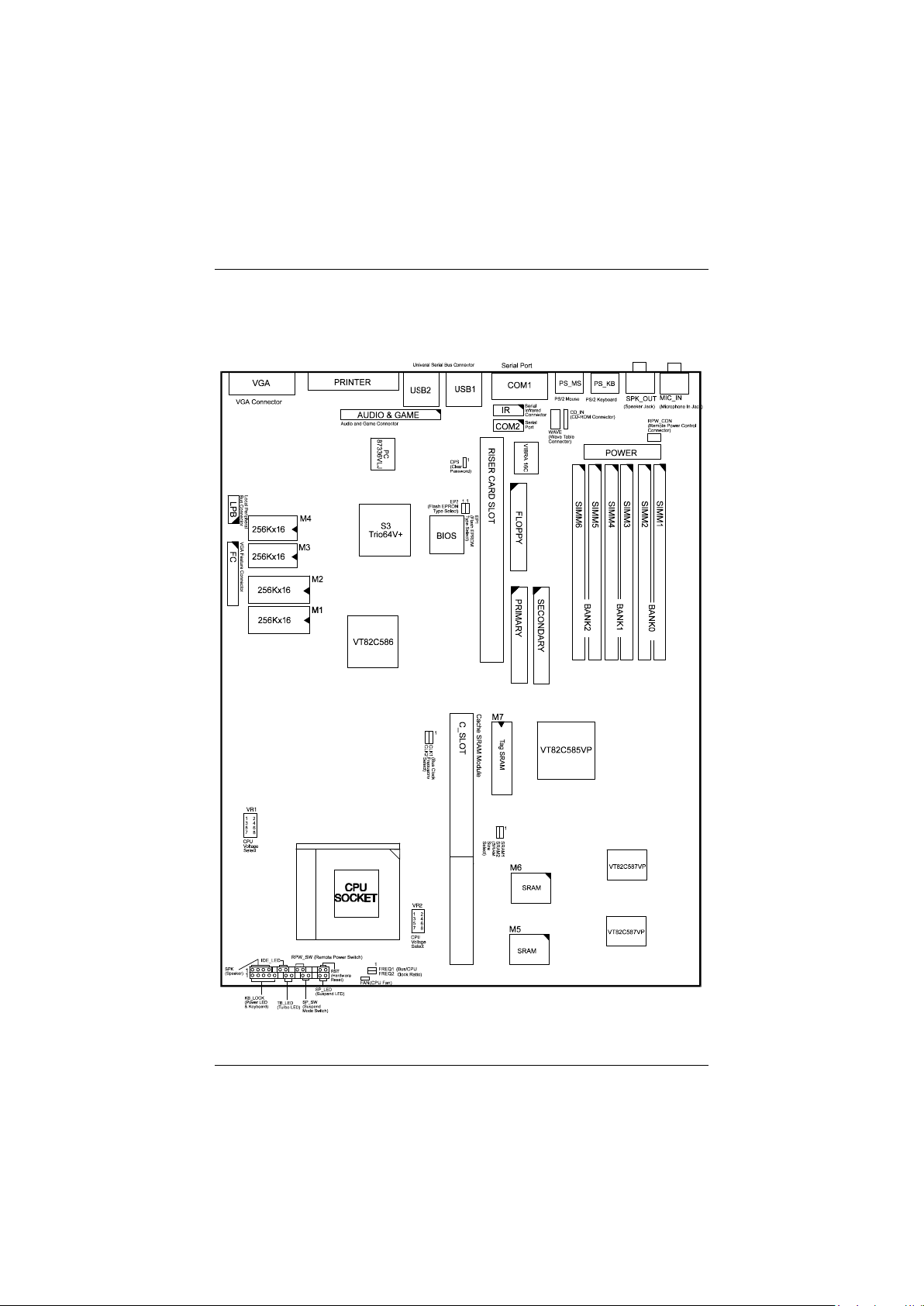
Mainboard Layout
6
Page 10
Installation Procedures
1). Set System Jumpers
Jumpers
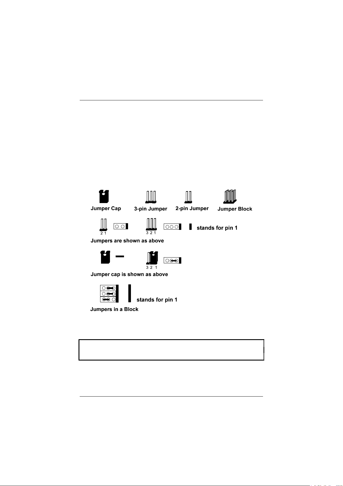
Jumpers are used to select the operation modes for your system. Some jumpers
on the board have three metal pins with each pin representing a different
function. To set a jumper, a black cap containing metal contacts is placed over
the jumper pins according to the required configuration. A jumper is said to be
shorted when the black cap has been placed on one or two of its pins. The types
of jumpers used in this manaul are shown below:
NOTE : Users are not encouraged to change the jumper settings not listed in
this manual. Changing the jumper settings improperly may adversely affect
system performance.
7
Page 11
PAK-2102 Mainboard Manual
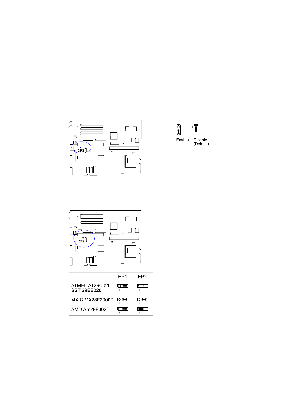
Clear Password: CPW
This jumper allows you to set the password configuration to Enabled or
Disabled. You may need to enable this jumper if you forget your password.
Flash EPROM Type Selection: EP1, EP2
This jumper allows you to configure the Flash EPROM chip.
8
Page 12

Installation Procedures
2). Install RAM Modules
DRAM Memory
The working space of the computer is the Random Access Memory (RAM). The
system cannot act upon data unless it is loaded into RAM. The system RAM is
comprised of industry-standard 72-pin Single In-line Memory Modules
(SIMMs).
The PAK-2102 is able to support standard FPM (Fast Page Mode) and EDO
(Extended Data Out) DRAM; and can accommodate onboard memory from 8
to 512MB using SIMMs. The mainboard has three memory banks: Bank 0, Bank
1, and Bank 2. Each bank has two SIMM sockets which can accept either a pair
of 4MB, 8BM, 16MB, 32MB, 64MB, or 128*MB SIMM in each socket. The
three banks allow different memory sizes of SIMMs (e.g. 4MB or 16MB);
however, you must populate each memory bank with the same memory size (e.g.
4MB & 4MB) of SIMM.
NOTE :
1. All memory banks use 72-pin memory modules.
2. * A SIMM of this size was not available for testing when this manual was
printed.
9
Page 13

SIMM 1 & 2
SIMM 3 & 4
SIMM 5 & 6
PAK-2102 Mainboard Manual
RAM Module Configuration
TOTAL
MEMORY
8MB 4MB & 4MB
16MB 8MB & 8MB
4MB & 4MB 4MB & 4MB
24MB 4MB & 4MB 4MB & 4MB 4MB & 4MB
8MB & 8MB 4MB & 4MB
32MB 8MB & 8MB 8MB & 8MB
8MB & 8MB 4MB & 4MB 4MB & 4MB
16MB & 16MB
40MB 8MB & 8MB 8MB & 8MB 4MB & 4MB
16MB & 16MB 4MB & 4MB
48MB 16MB & 16MB 8MB & 8MB
8MB & 8MB 8MB & 8MB 8MB & 8MB
16MB & 16MB 4MB & 4MB 4MB & 4MB
64MB 16MB & 16MB 8MB & 8MB 8MB & 8MB
16MB & 16MB 16MB & 16MB
32MB & 32MB
72MB 32MB & 32MB 4MB & 4MB
80MB 32MB & 32MB 8MB & 8MB
32MB & 32MB 8MB & 8MB
96MB 32MB & 32MB 16MB & 16MB
32MB & 32MB 8MB & 8MB 8MB & 8MB
16MB & 16MB 16MB & 16MB 16MB & 16MB
(continued on the next page)
(Bank 0)
(Bank 1)
(Bank 2)
10
Page 14

SIMM 1 & 2
MM 3 & 4
SIMM 5 & 6
Installation Procedures
TOTAL
MEMORY
128MB 32MB & 32MB 32MB & 32MB
64MB & 64MB
32MB & 32MB 16MB & 16MB 16MB & 16MB
136MB 64MB & 64MB 4MB & 4MB
144MB 64MB & 64MB 4MB & 4MB 4MB & 4MB
64MB & 64MB
160MB 64MB & 64MB 8MB & 8MB 8MB & 8MB
64MB & 64MB 16MB & 16MB
192MB 64MB & 64MB 32MB & 32MB
64MB & 64MB 16MB & 16MB 16MB & 16MB
32MB & 32MB 32MB & 32MB 32MB & 32MB
256MB 64MB & 64MB 32MB & 32MB 32MB & 32MB
64MB & 64MB 64MB & 64MB
128MB* & 128MB*
264MB 128MB* & 128MB* 4MB & 4MB
272MB 128MB* & 128MB* 4MB & 4MB 4MB & 4MB
128MB* & 128MB* 8MB & 8MB
288MB 128MB* & 128MB* 8MB & 8MB 8MB & 8MB
128MB* & 128MB* 16MB & 16MB
320MB 128MB* & 128MB* 16MB & 16MB 16MB & 16MB
128MB* & 128MB* 32MB & 32MB
384MB 64MB & 64MB 64MB & 64MB 64MB & 64MB
128MB* & 128MB* 64MB & 64MB
512MB 128MB* & 128MB* 64MB & 64MB 64MB & 64MB
128MB* & 128MB*
(Bank 0)
SI
(Bank 1)
(Bank 2)
NOTE : * A SIMM of this size was not available for testing when this manual
was printed.
11
Page 15
PAK-2102 Mainboard Manual
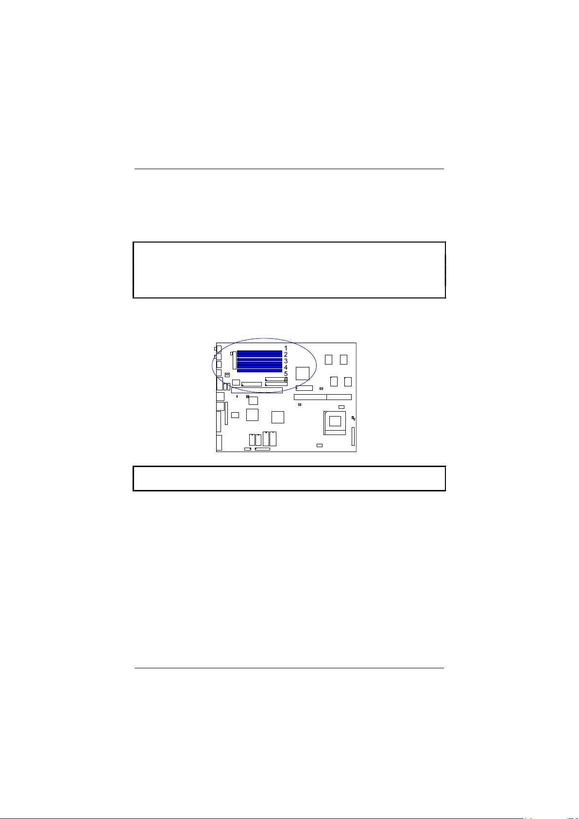
Install SIMMs
Complete the following procedures to install SIMMs:
CAUTION :
1. Always turn the system power off before installing or removing any
device.
2. Always observe static electricity precautions.
See “Handling Precautions” at the start of this manual.
1. Locate the SIMM slots on the mainboard. (See figure below.)
NOTE : SIMMs in each bank must be of the same type; and the BIOS
automatically configures the memory size.
12
Page 16
Installation Procedures
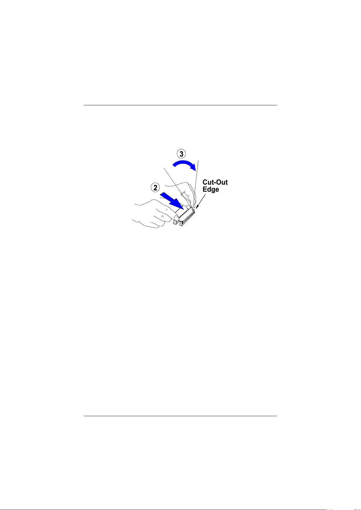
2. Carefully fit a SIMM at a 45 degree angle into each empty socket to be
populated. All the SIMMs must face the same direction.
3. Swing each SIMM into its upright, locked position.
When locking a SIMM in place, push on each end of the SIMM - do not
push in the middle, as shown above.
Remove SIMMs
To remove the SIMMs, pull the retaining latch on both ends of the socket and
reverse the procedure above.
13
Page 17

PAK-2102 Mainboard Manual
Cache Memory
Cache memory access is very fast compared to main memory access. The cache
holds data for imminent use. Since cache memory is from five to more than ten
times faster than main memory, the CPU’s access time is reduced, giving you
better system performance.
Pentium mainboards may implement various types of L2 cache SRAMs. Pipeline
Burst SRAM is one of them, delivering the best price performance ratio. They
perform much better than asynchronous SRAMs.
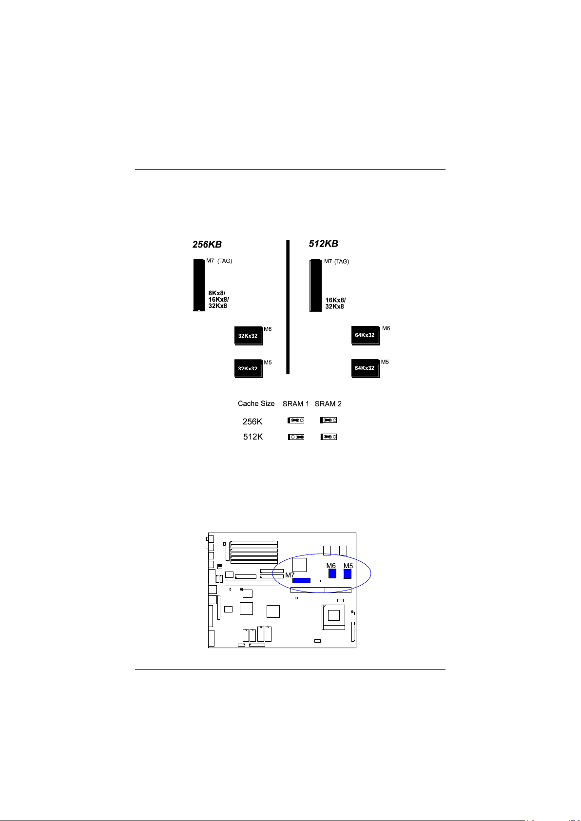
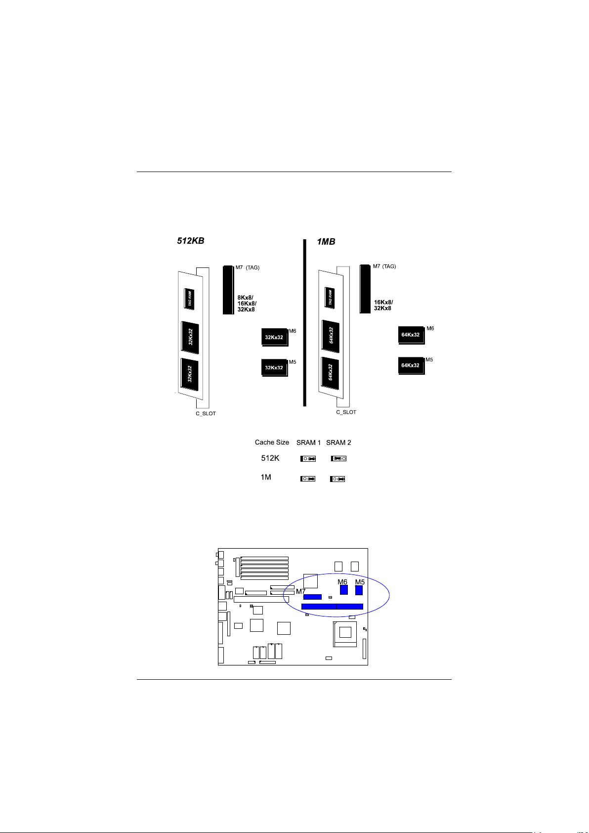
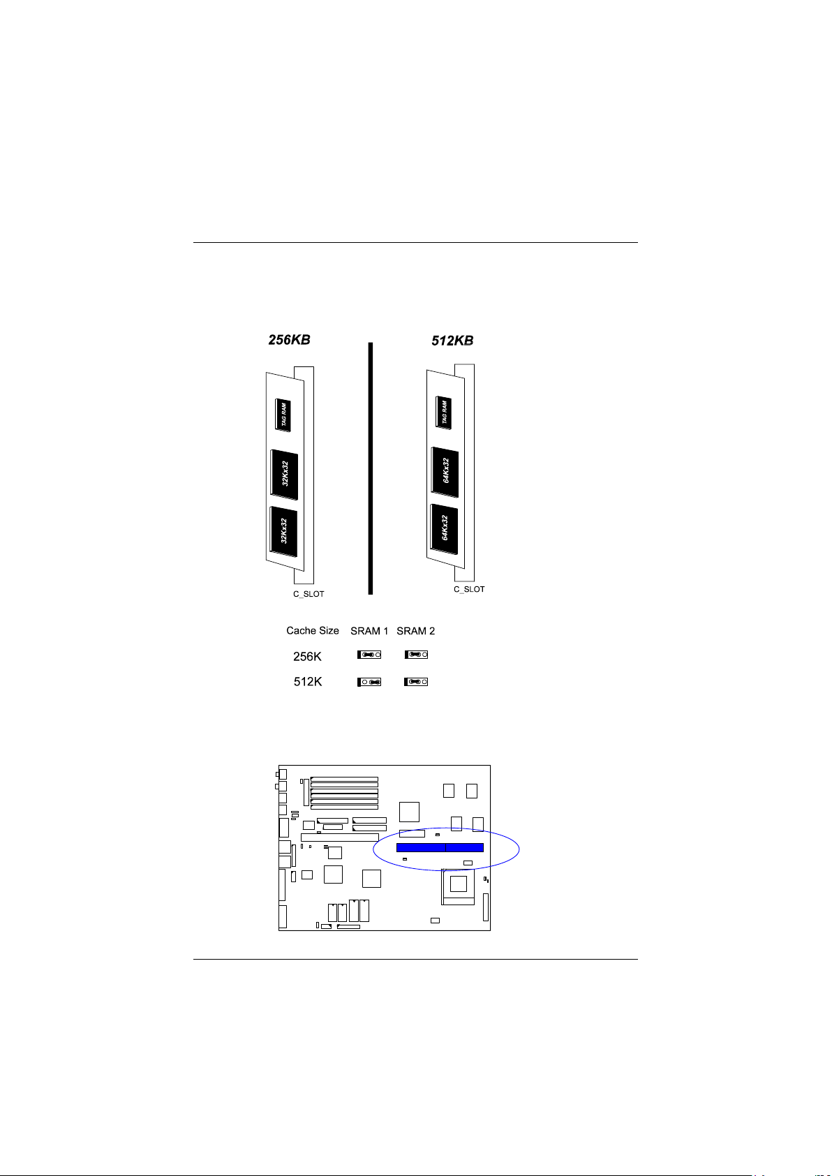
The PAK-2102 comes with onboard 256KB/512KB synchronous 3V Pipeline
Burst SRAMs or a 256KB/512KB cache RAM module (FIC’s PC512K-3.0 is
recommended) that can be installed on the cache RAM module slot.
NOTE : Use the correct chips for the amount of cache memory you want to
add. Install both the correct SRAM module and tag SRAM.
14
Page 18
Onboard Cache RAM (256KB/512KB)
Installation Procedures
15
Page 19
PAK-2102 Mainboard Manual
Onboard C ache RAM and RAM Module Mixture (512KB/1MB)
16
Page 20
RAM Module (256KB/512KB)
Installation Procedures
17
Page 21
PAK-2102 Mainboard Manual
3). Install the CPU
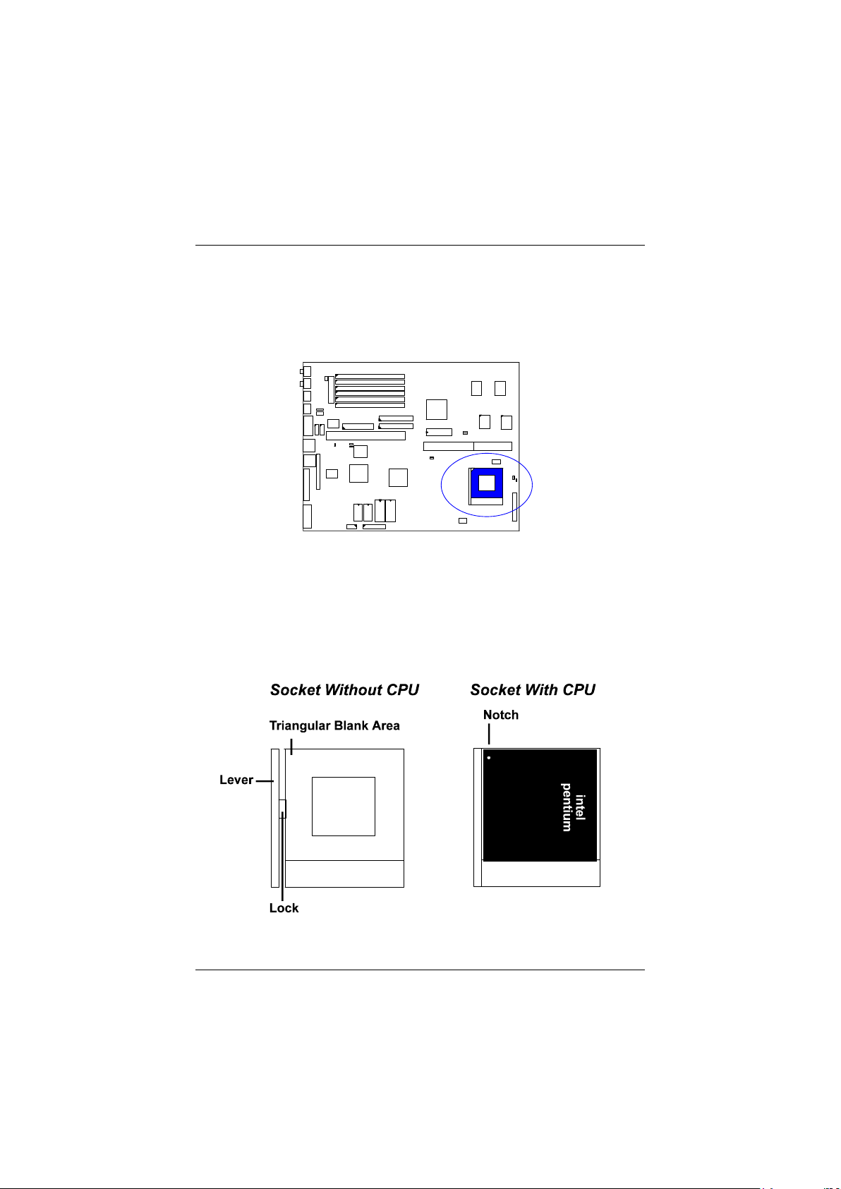
The CPU module resides in the Zero Insertion Force (ZIF) socket on the
mainboard.
18
Page 22

Installation Procedures
CAUTION :
1. Always turn the system power off before installing or removing any
device.
2. Always observe static electricity precautions.
See “Handling Precautions” at the start of this manual.
3. Inserting the CPU chip incorrectly may damage the chip.
To install the CPU, do the following:
1. Lift the lever on the side of the CPU socket.
2. Handle the chip by its edges and try not to touch any of the pins.
3. Place the CPU in the socket. The chip has a notch to correctly orientate the
chip. Align the notch with pin one of the socket. Pin one is located in the
blank triangular area. Do not force the chip. The CPU should slide easily
into the socket.
4. Swing the lever to the down position to lock the CPU in place.
5. See the following sections for information on the CPU jumpers settings.
19
Page 23
PAK-2102 Mainboard Manual
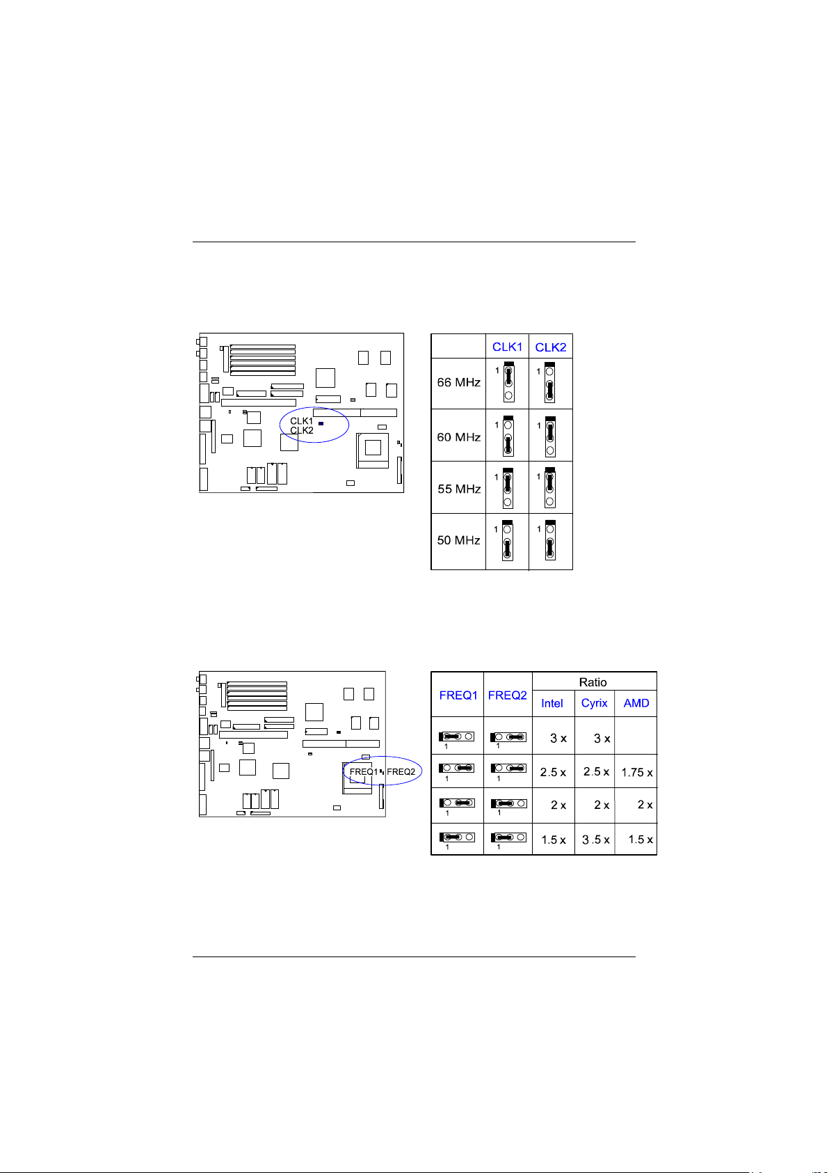
CPU External Clock (BUS) Frequency: CLK1, CLK2
The table below shows the jumper settings for the different CPU speed
configurations.
CPU to Bus Frequency Ratio: FREQ1, FREQ2
These two jumpers are used in combination to decide the ratio of the internal
frequency of the CPU to the bus clock.
20
Page 24
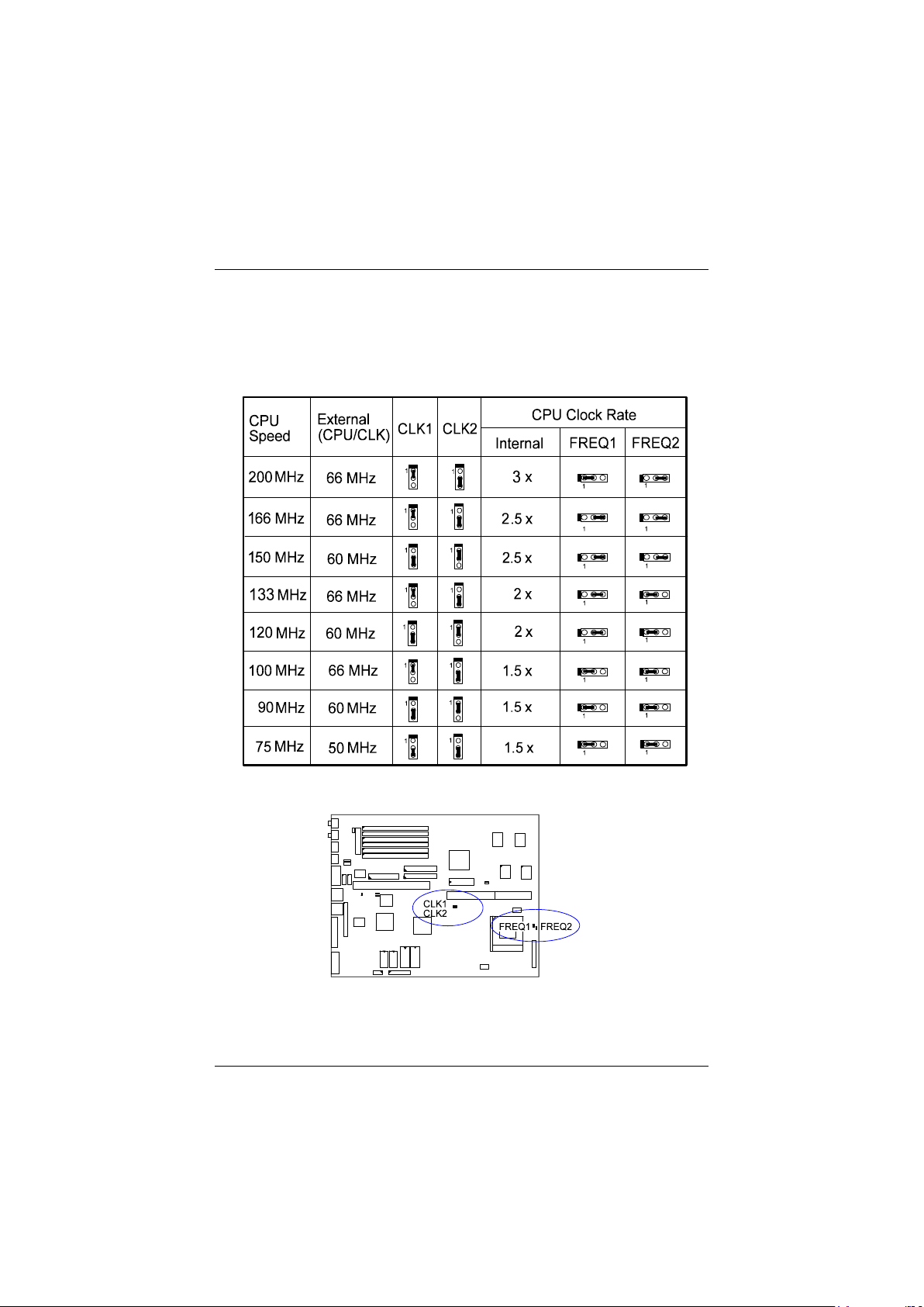
Intel Pentium CPUs
Frequency
Installation Procedures
21
Page 25
PAK-2102 Mainboard Manual
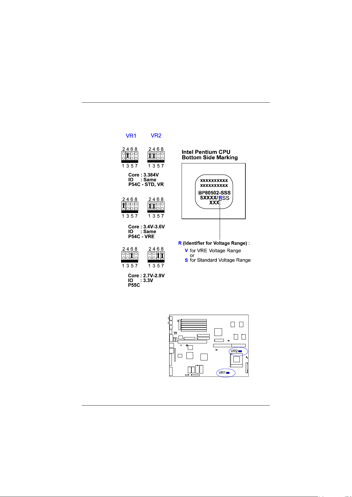
Voltage
22
Page 26
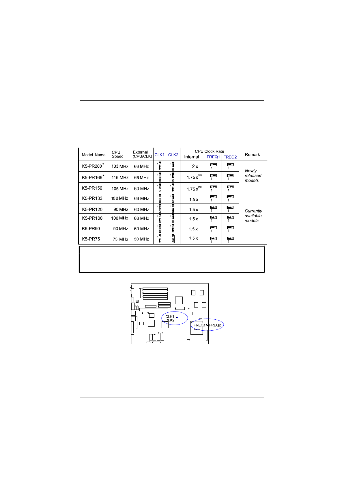
AMD-K5 CPUs
Frequency
Installation Procedures
NOTE :
* This CPU had not been tested when this manual was printed.
** For AMD CPUs only, jumper FREQ1/FREQ2 can be set for 1.75x bus
ratratio.
23
Page 27
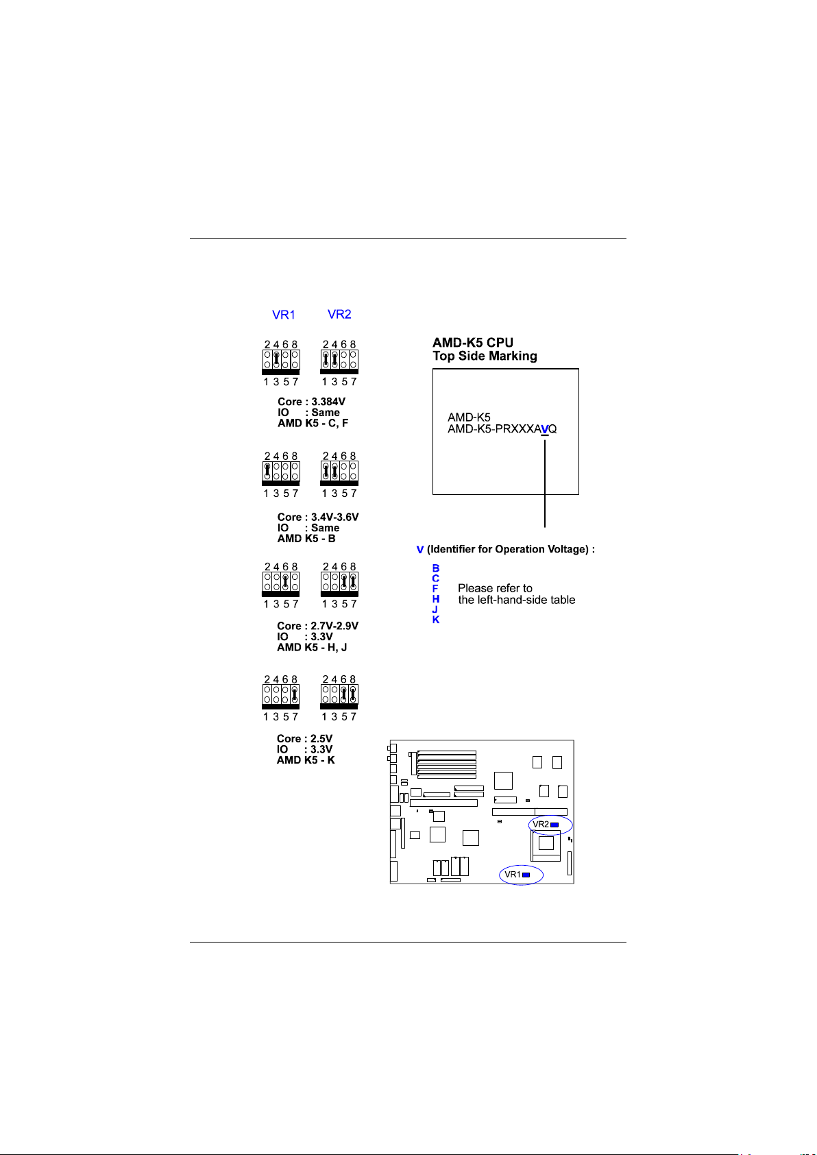
PAK-2102 Mainboard Manual
Voltage
24
Page 28
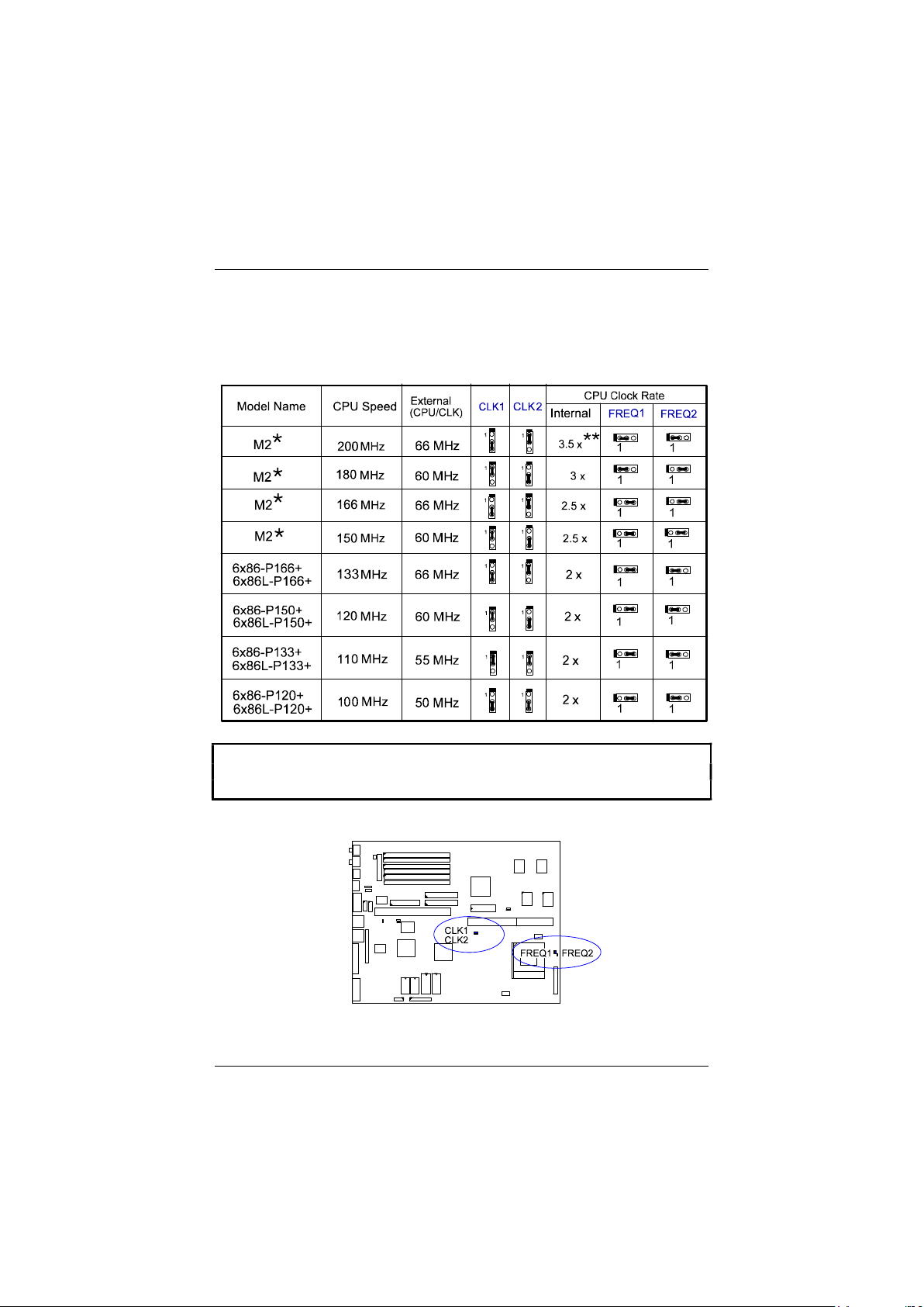
Cyrix 6x86 CPUs
Frequency
Installation Procedures
NOTE :
* This CPU had not been tested when this manual was printed.
** For Cyrix/IBM CPUs only, FREQ1/2 can be set for 3.5x bus ratio.
25
Page 29
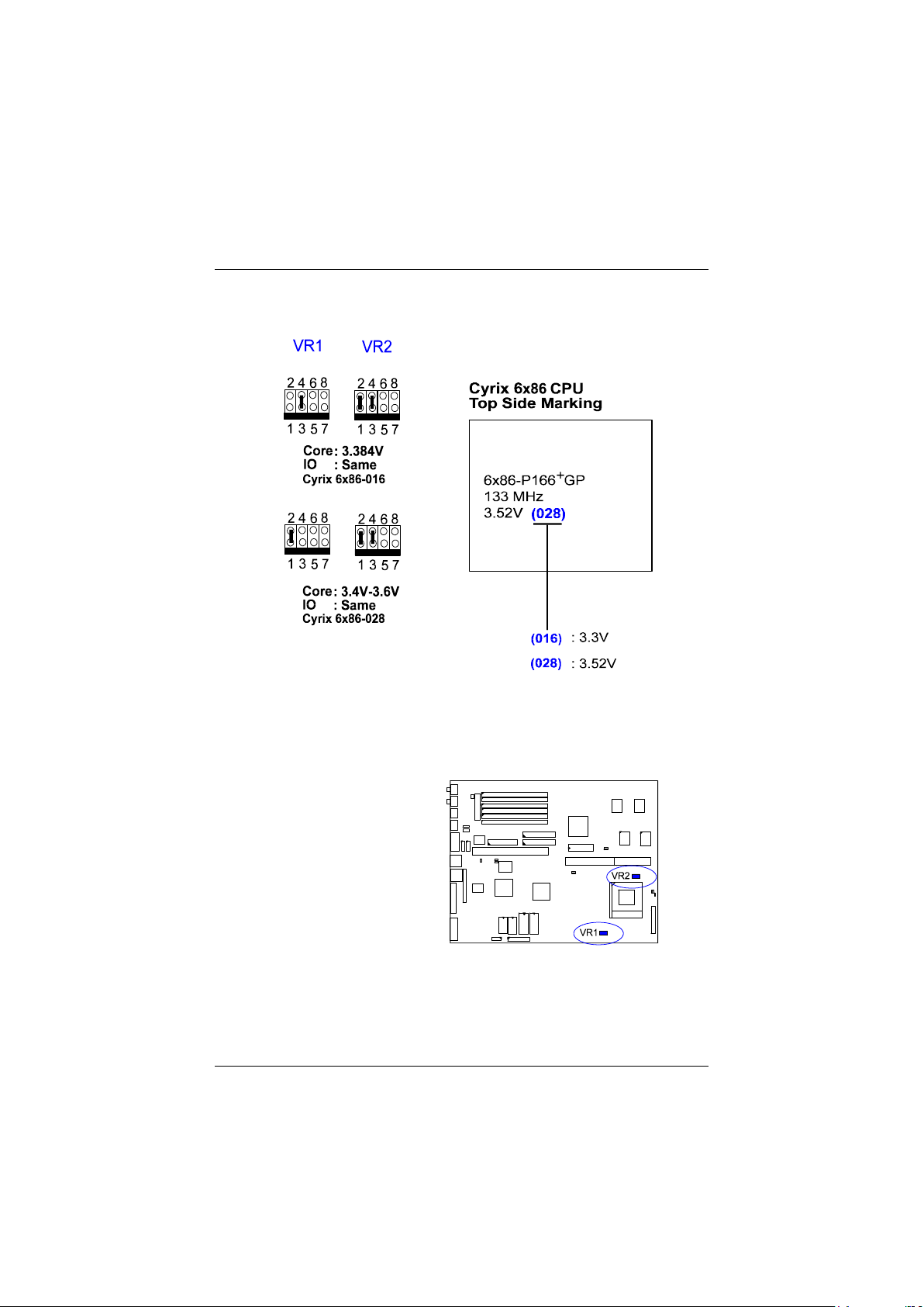
PAK-2102 Mainboard Manual
Voltage
26
Page 30
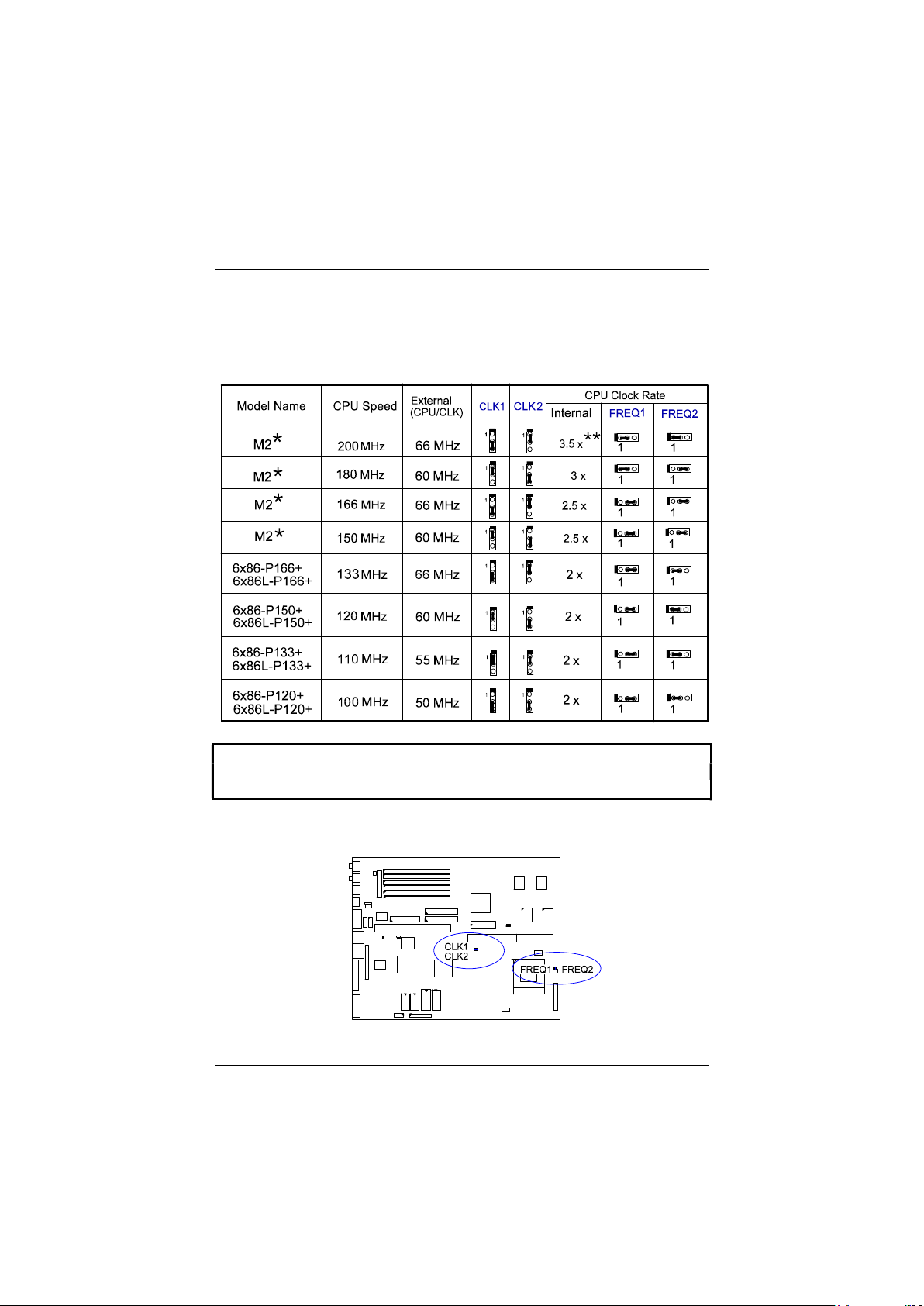
IBM 6x86 CPUs
Frequency
Installation Procedures
NOTE :
* This CPU had not been tested when this manual was printed.
** For Cyrix/IBM CPUs only, FREQ1/2 can be set for 3.5x bus ratio.
27
Page 31
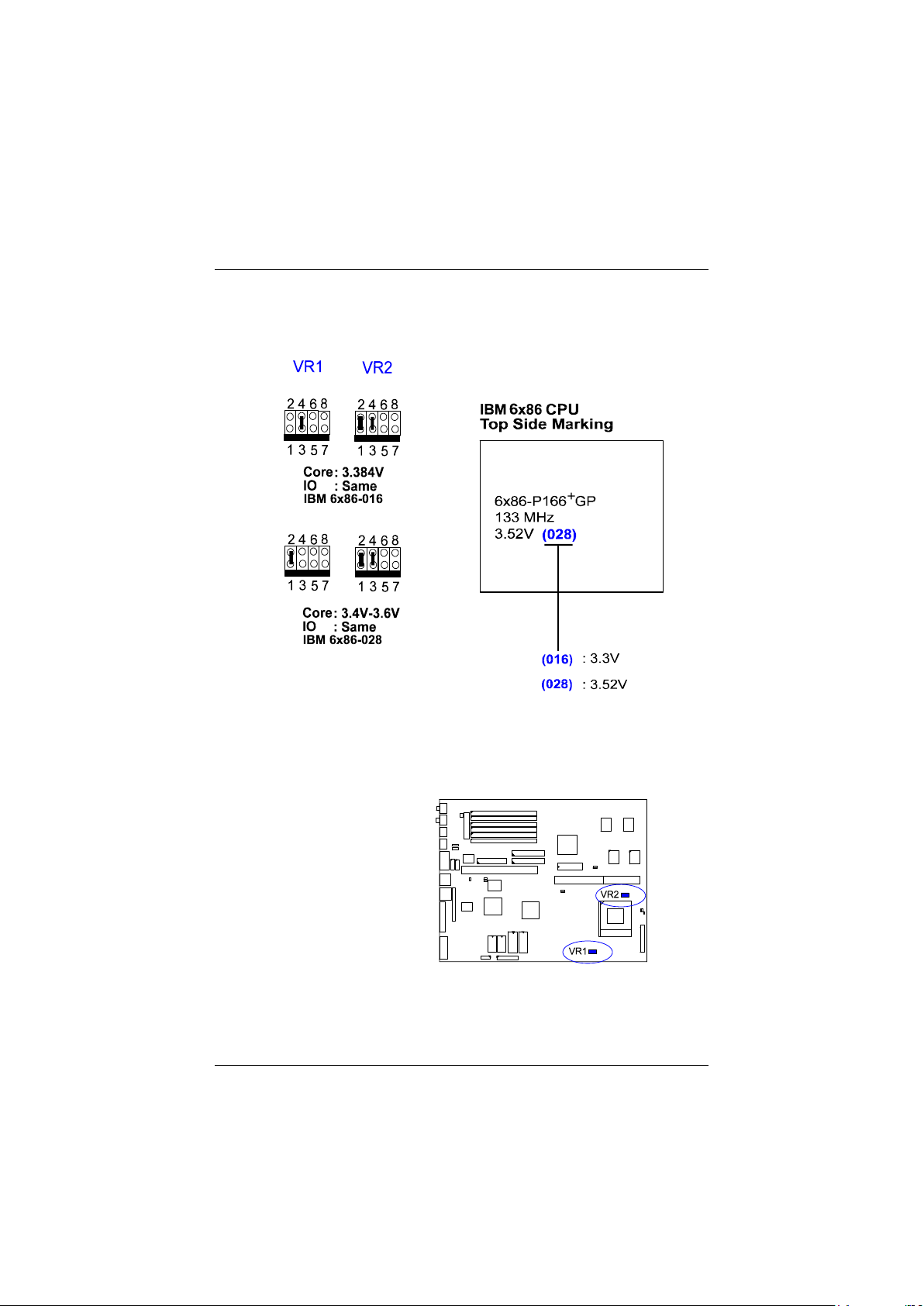
PAK-2102 Mainboard Manual
Voltage
28
Page 32
Installation Procedures
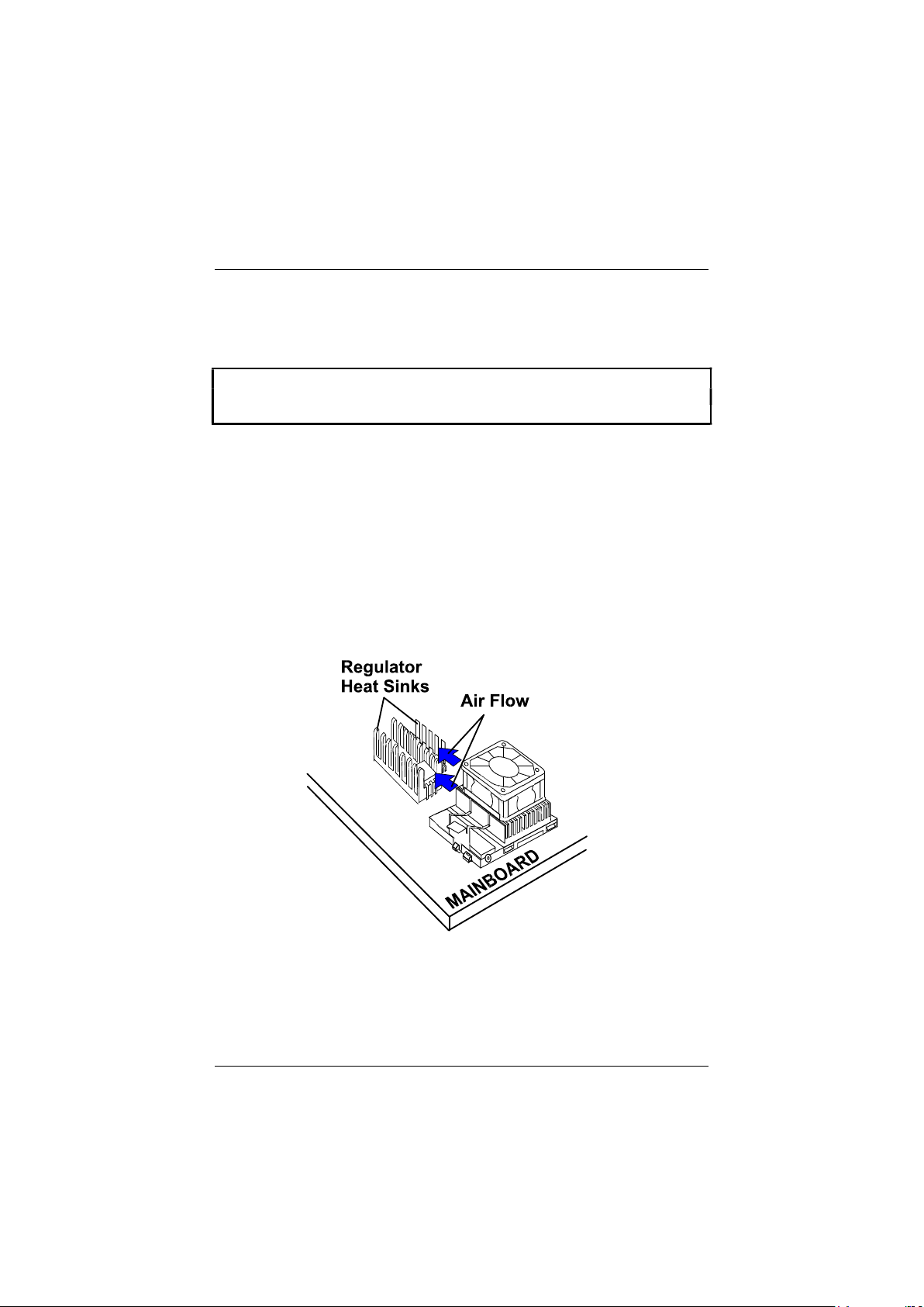
Installation of Cyrix (or IBM) 6x86 CPU Fan
CAUTION : When you install a Cyrix (or IBM) 6x86 CPU fan, please pay
attention to the direction of the air flow. Make sure that it lowers the
temperature of the regulator. Otherwise, the system may overheat.
We recommend that you use one of the following two CPU fans for the Cyrix (or
IBM) 6x86 CPU when you install the fan on the mainboard.
1). Supplier : BIRCHTECK, Taiwan (Phone : 886-2-7935677)
Model Number - BEC6x86B2.
2). Supplier : Cyrix (or IBM). The fan comes with the Cyrix (or IBM) 6x86
CPU purchase. For the stable system performance, make sure
that the air flow blow toward the regulator the temperature
of the regulator.
29
Page 33

PAK-2102 Mainboard Manual
4). Install Expansion Cards
Add-on cards are printed circuit boards that, when connected to the mainboard,
increase the capabilities of your system. For example, add-on cards can provide
video and sound capabilities.
CAUTION :
1. Always turn the system power off before installing or removing any
device.
2. Always observe static electricity precautions.
See “Handling Precautions” at the start of this manual.
To install an add-on card, do the following:
1. Insert the target add-on card on the riser card.
2. Remove the chassis cover and select an available expansion slot.
3. Remove the corresponding slot cover from the chassis.
Unscrew the mounting screw that secures the slot cover and pull the slot
cover out from the chassis. Keep the slot cover mounting screw nearby.
4. Hold the edge of the riser card, carefully align the edge with the expansion
slot.
5. Push the riser card firmly into the riser card slot.
6. Secure the add-on card with the mounting screw removed in Step 4. Make
sure that the add-on card has been placed evenly and completely into the
expansion slot.
30
Page 34
Installation Procedures
5). Connect Cables and Power Supply
Audio-In Connector: CD-IN
This 4-pin male connector is linked to the AUDIO-OUT port of your CD-ROM
device via a ribbon cable.
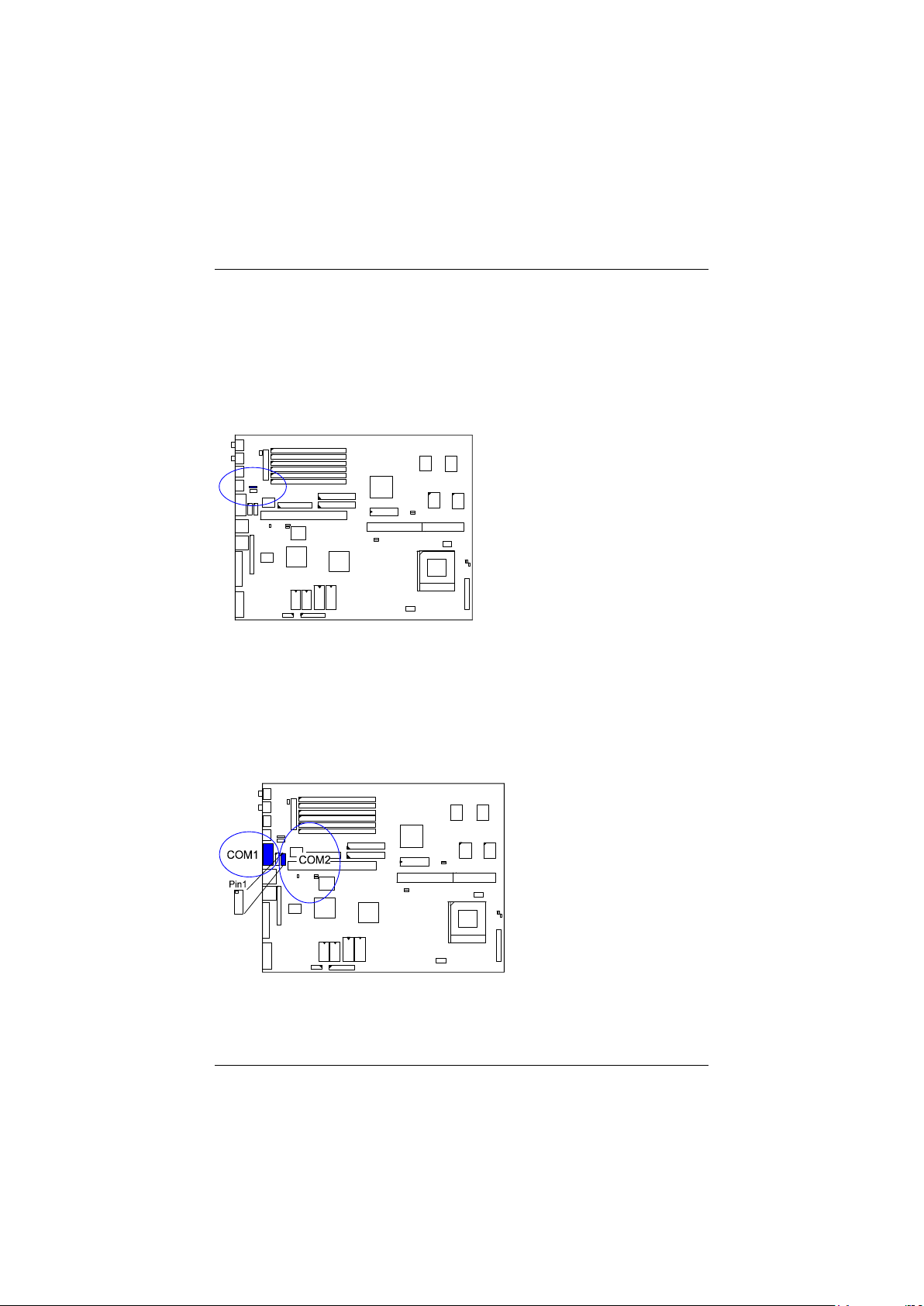
Serial Port Connectors: COM1, COM2
The COM1 is a 9-pin D-type male connector that allows you to connect with
your devices that take serial ports, such as a serial mouse or a modem. The
COM2 Port, is a 2x5 pin-head onboard connecto, can be used as an alternative
IR Port. Usually, your serial mouse is connected to COM1. Your modem is
linked to COM2. When you do not use the modem, you can set the BIOS to let
COM2 be an IR port to save a dedicated SIR port.
31
Page 35
PAK-2102 Mainboard Manual
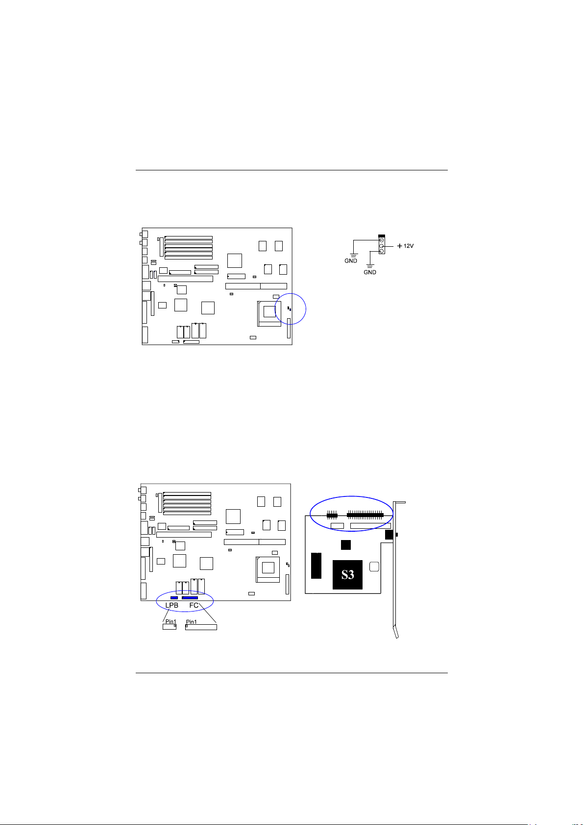
CPU Fan Connector: FAN
This connector is linked to the CPU fan.
Hardware MPEG Card Connector: FC, LPB
An optional MPEG card 1stGafx-CP3™ will be installed on an available PCI
slot on the mainboard to improve the visual quality.
The FC connector, a 2x17 pin male connector, are connected to the MPEG card
(together with the LPB connector) via a ribbon cable for utilizing the VGA
feature of the MPEG card.
The LPB (Local Peripheral Bus) connector, a 2x5 pin male connector, is used
together with the FC connector.
32
Page 36
Installation Procedures
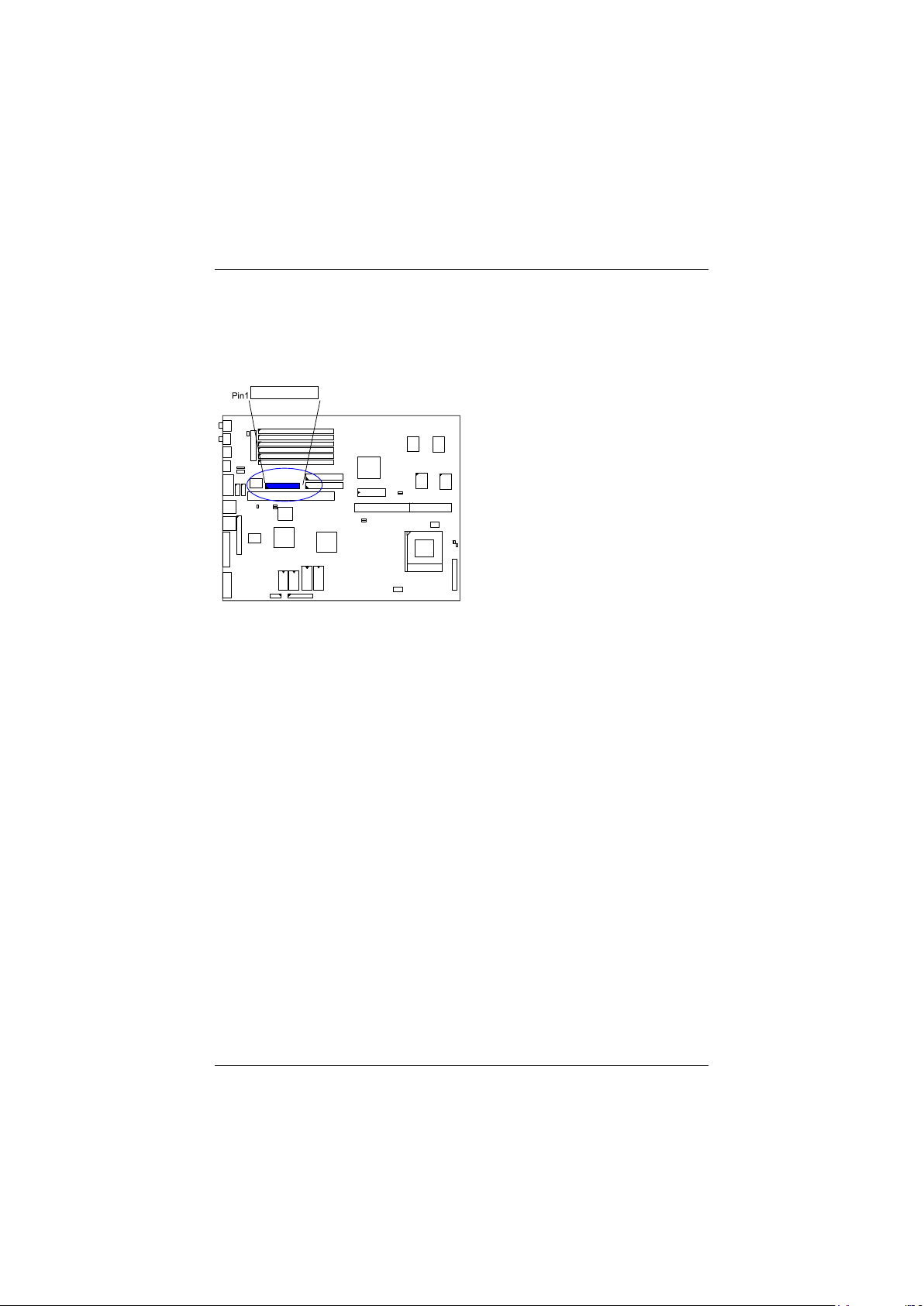
Floppy Diskette Drive Connector: FLOPPY
This 2x17 pin male connector connects to your floppy diskette drive (FDD)
using the cable that is provided with this mainboard.
33
Page 37
system
PAK-2102 Mainboard Manual
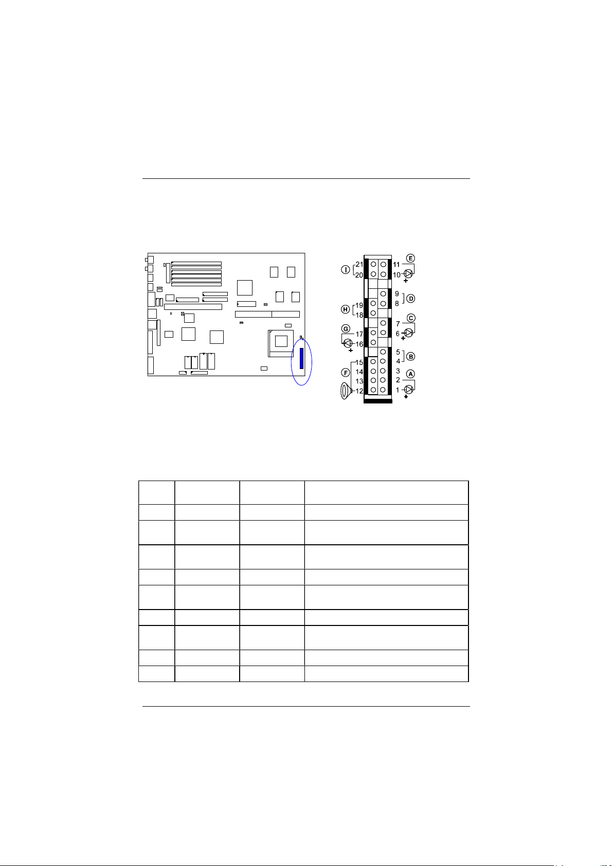
Front Panel Block Connector: F_PNL
This block connector includes: PW_LED, KB_LOCK, TB_LED, SP_SW, SPK,
SP_LED, IDE_LED, RPW_SW, and RST connectors.
Item Connector Pin Type Feature
A PW_LED 2-pin male
B KB_LOCK 2-pin male
C TB_LED 2-pin male
D SP_SW 2-pin male
E SP_LED 2-pin male
F SPK 4-pin male
G IDE_LED 2-pin male
H RPW_SW 2-pin male
I RST 2-pin male
indicates the system power status
allows the keyboard to access the
indicates the system speed is in
normal or turbo speed
Suspend mode switch
indicates the system into Suspend
mode when LED lit
connects to speaker
indicates the IDE HDD I/O access
LED lit
remote power switch
allows you to reset the system
34
Page 38
Installation Procedures
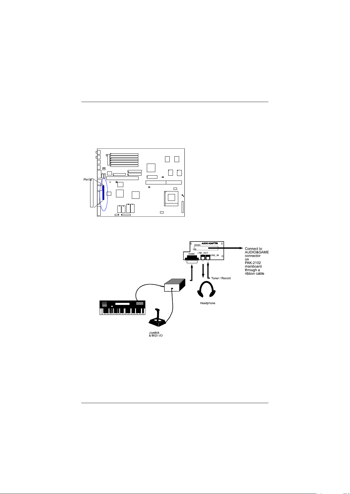
Audio and Game Connector: AUDIO&GAME
This connector is connected to the audio adapter card via a ribbon cable. The
adapter card provides a 15-pin D-type female game port, a LINE_IN external
jack and a LINE_OUT jack. The game port also functions as a MIDI port.
35
Page 39
PAK-2102 Mainboard Manual
Infrared Connector: IR
This 2x5 pin male connector is used for connecting to the infrared (SIR) port and
allows transmission of data to another system which also supports the SIR
feature.
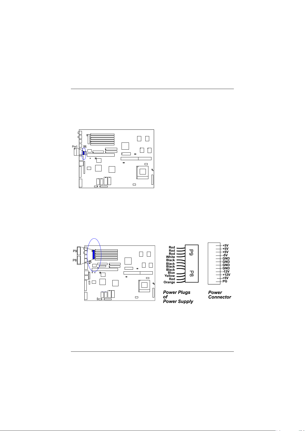
Power Connector: POWER
This 12 pin block connector is used for connecting to the standard 5V power
supply. In the picture below, notice that, in most cases, there are two marks P8
and P9 on the surface of the connector. You have to insert the P8 plug into the
P8 section of the connector, and so forth for P9. Two black wires must be in the
middle.
36
Page 40
Installation Procedures
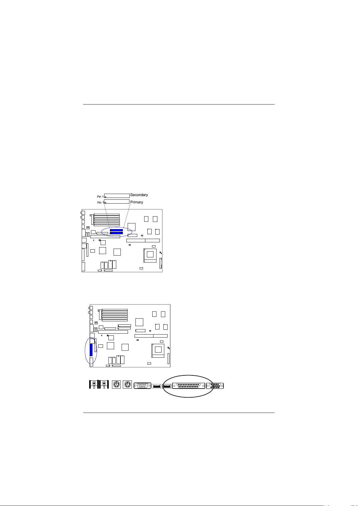
IDE HDD Device Connector: PRIMARY and SECONDARY
These two 2x20 pin male connectors are used for your IDE hard disks. If you
have one IDE hard disk, connect it to the PRIMARY connector using the IDE
HDD flat cable provided with the mainboard. The BIOS auto detection sets it to
be a Primary Master disk. If you want to install another IDE hard disk or
CD-ROM, please use the SECONDARY connector. If two hard disks are
connected to the PRIMARY connector using the same cable, one of them is the
master drive, the other one is the slave drive. You may need to set jumpers for
the slave drive; please refer to the HDD manual for details.
Printer Connector: PRINTER
This 26-pin D-type female connector is attached to your printer via a cable.
37
Page 41
PAK-2102 Mainboard Manual
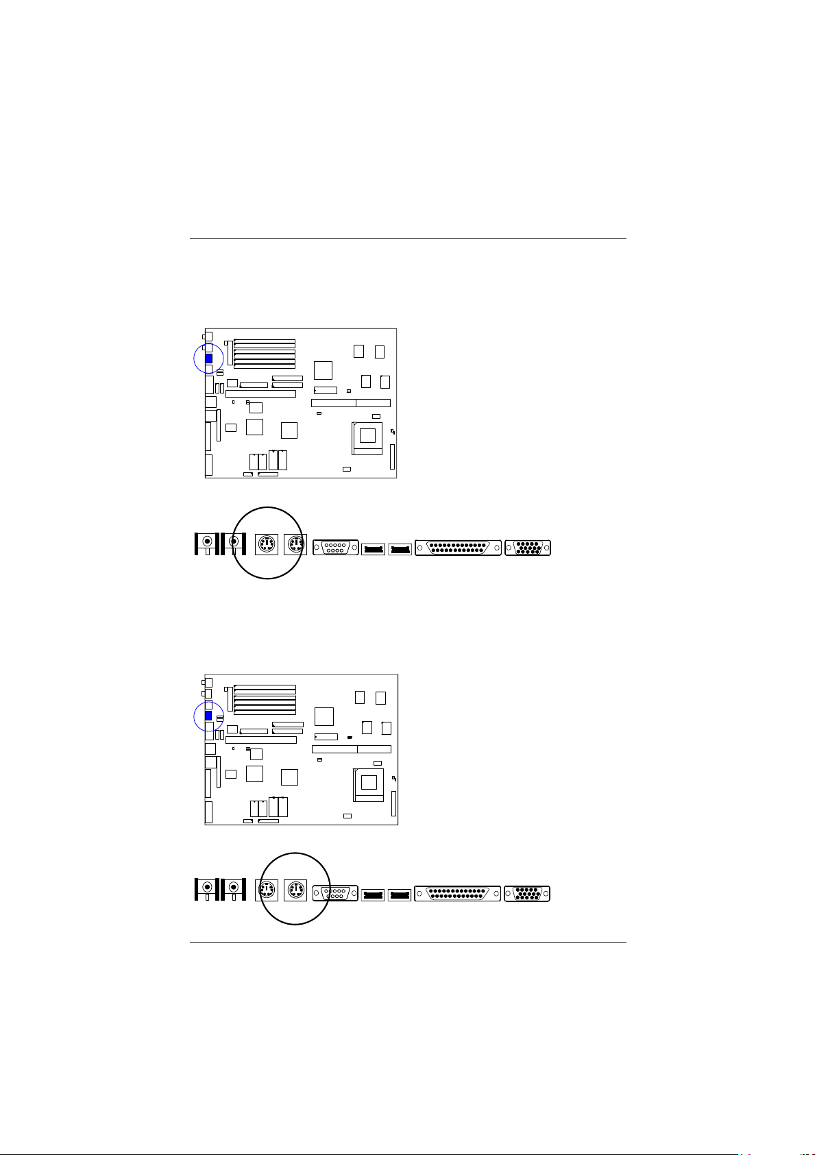
PS/2 Keyboard Connector: PS2_KB
This 5 pin female connector is connected to the PS/2 keyboard.
PS/2 Mouse Connector: PS2_MS
This 5 pin female connector is connected to the PS/2 mouse.
38
Page 42
Installation Procedures
Remote Power Supply Connector: RPW_CON
This 3 pin male connector allows you to enable (or disable) the system power if
the RPW_SW is on (or off).
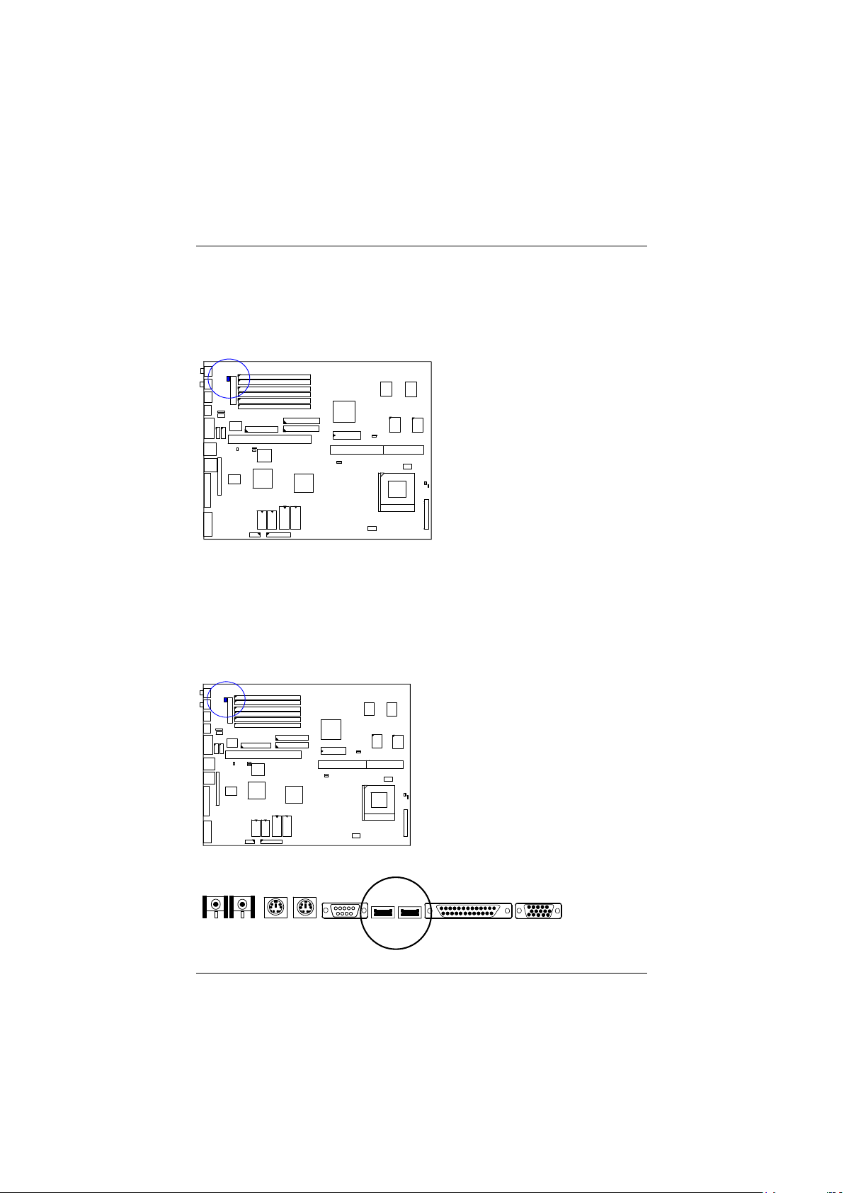
Universal Serial Bus Connectors (reserved for future upgrade)
This connects to the port that allows you to attach a USB hub. The USB
connectors are built-in for future upgrade of devices or peripherals that support
Universal Serial Bus features.
39
Page 43
PAK-2102 Mainboard Manual
VGA Connector: VGA
VGA Subsystem
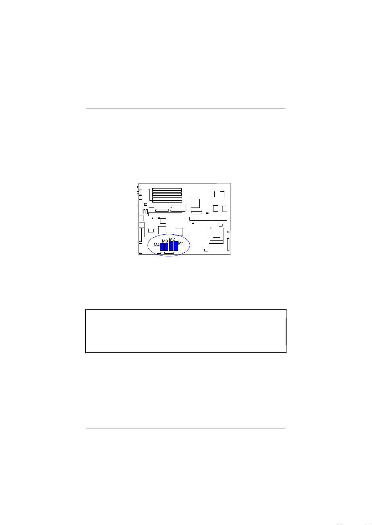
The mainboard has built-in VGA controller that supports 1280x1024 resolutions.
The related data about resolutions are listed in the next page. To upgrade the
onboard VGA DRAM size to 2MB, insert two 256Kx16Bits-7 (SOJ type)
DRAM at locations M1, M2.
The PAK-2102 supplies drivers for DOS and Windows-based programs;
software drivers for other operating systems may be available in the future or
upon request. These drivers will help you to utilize and to enhance the video
subsystem of your computer system. The driver disk contains a READ.ME file
that is accessible through any word processor using the ASCII or non-document
mode.
NOTE :
1. Make backup disks of the original disks and use the backup ones.
2. Use the correct chips for the amount of DRAMs you to add.
3. Observe static electricity precautions.
4. Read the READ.ME file in the driver disk for the installation and recent
updates.
40
Page 44

640x480
256 37.51
75.02
31.500
2
D, R
640x480
32K 37.51
75.02
31.500
2 R
800x600
256 46.92
75.02
49.500
2
D, R
800x600
64K 48.02
71.99
50.000
2 R
1024x768
256 60.02
74.96
80.000
2
D, R
Installation Procedures
Display
Your system has a standard memory of 2MB and provides an onboard VGA
controller installed on your mainboard that supports various resolutions up to
1024 x 1280 in 16 colors under both the standard and enhanced VGA modes. It
also supports 132-column text modes and non-interlaced monitors up to 72Hz
refresh rates.
VGA drivers and utilities have been provided with the installation diskettes to
enable you to take full advantage of the display capabilities of your monitor
while using different application programs. Please refer to the README file in
the utility diskettes or ask your dealer for more information or documentation on
these utilities and drivers.
The following table shows the VGA resolutions supported by the system.
Resolution
Colors
Sweep
Rate
(KHz)
Refresh
Rate
(Hz)
Dot
Clock
(MHz)
Min.
Video
Memory
(MB)
Display
=D
Render-
ing = R
640x480 64K 37.52 75.02 31.500 2 R
640x480 16M 37.51 75.02 31.500 2 R
1280x1024 256 46.46 43.4 (I) 75.000 2 D
41
Page 45
PAK-2102 Mainboard Manual
The Connector
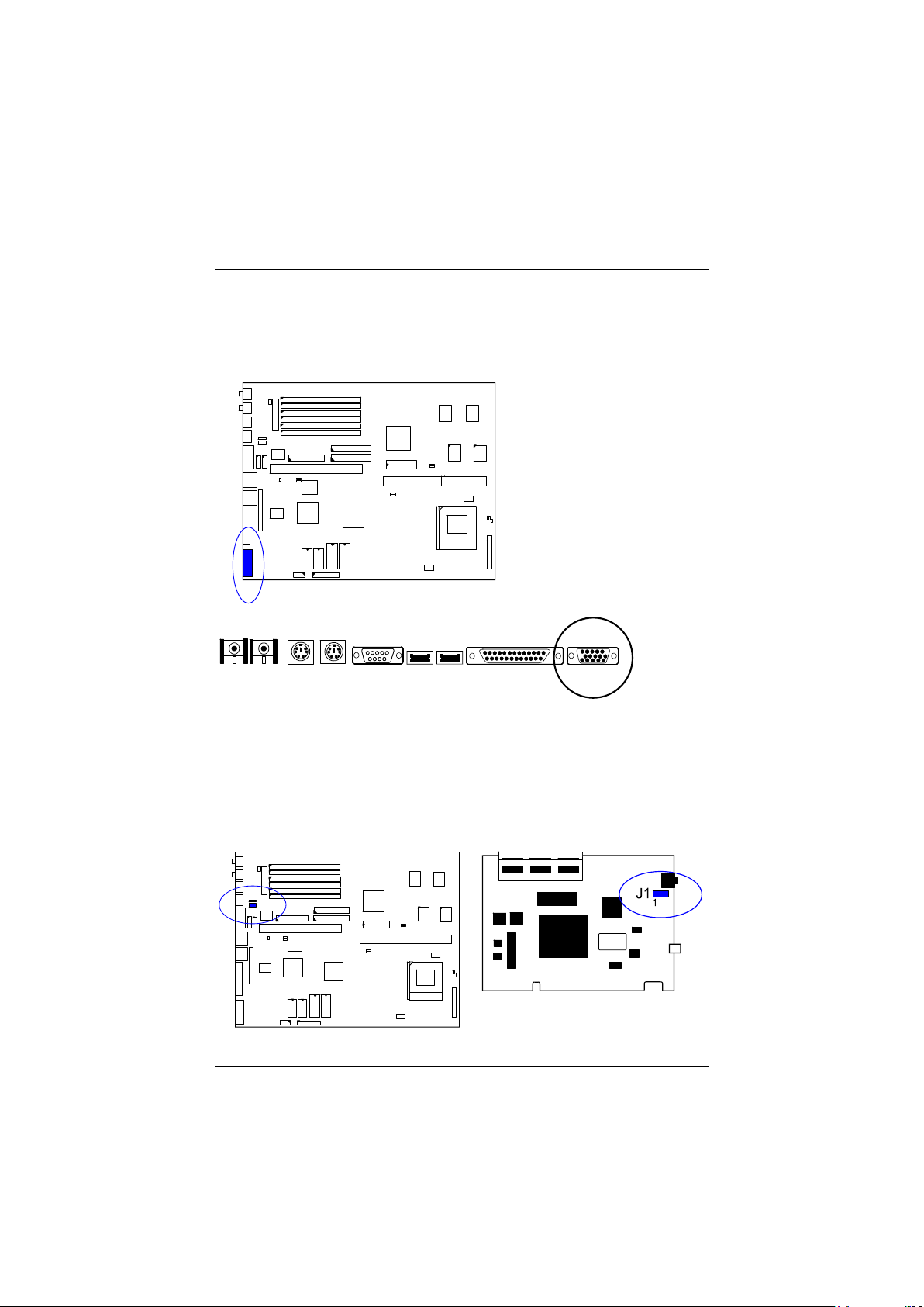
This 15 pin D-type female connector is connected to the VGA monitor.
Wave Table Connector: WAVE
The onboard audio system controller, CT2505, and FM synthesizser together
with an optional wave table card CT1920 contributes an even better audio
effect. The wave table card is installed on an availlable ISA slot. Use a ribbon
cable to connect J1 connector on the wave table card with the WAVE connector
(2x4 pin male) on the mainboard.
42
Page 46

Installation Procedures
43
 Loading...