

Page 1
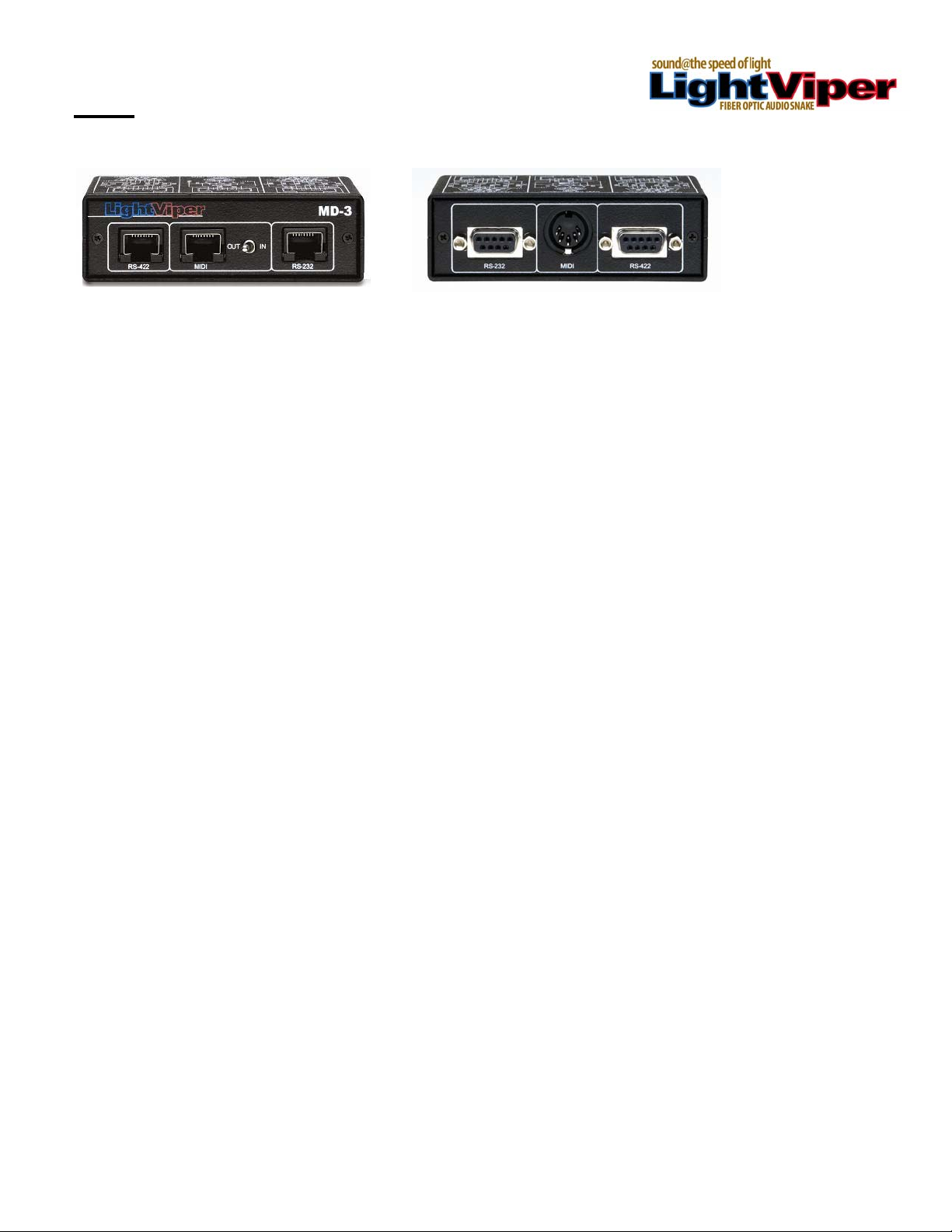
MD-3
Functional Considerations
The Light Viper MD-3 is very simple device designed to translate RS-232, RS-422 and MIDI data into TTL
control data, thereby allowing it to be transported via fiber through the “control circuit” connectors that
appear on the LightViper VIS-1832, VIS-4832, VIM-1832, VIM-1032, VIM-1808 and VIM-0808. The MD-3
is designed to be used in pairs. A single MD-3 contains (1) RS-232 connector, (1) RS-422 connector, and
(1) MIDI connector located on the front of the MD-3. On the back of the unit there are (3) corresponding
RJ-45 connectors, and a switch to determine MIDI send/receive status.
Standard Components
In its standard configuration, the Light Viper MD-3 data translation and transport system consists of three
primary components:
2 ea. Of the MD-3 - This is the hardware interface. One unit is placed on each end of the data
connection.
RS-422, 232 or MIDI input / output cables – These cables connect the devices transmitting the control
signals into the MD-3 on the “send” side of the data path, as well as connecting the data output from the
MD-3 to the devices on the receiving end of the data path.
CAT-5 jumpers – one CAT-5 jumper cable at each end is required for each of the data protocols being
translated (RS-422, RS-232 or MIDI). These connect the RJ-45 connectors on the MD-3’s to the
LightViper “Control Circuits” connectors on both the send and receive en d of the data path.
Getting Started
Setting up and using your Light Viper MD-3’s is quick and simple. Just follow these steps:
1. Mount (1) MD-3 close to the VIM-1832, VIM-1032 or VIM-1808 (“send” or mixer end)
2. Mount (1) MD-3 close to the VIS-1832, VIS-4832 or VIM-0808 (“receive” or stage end).
3. Connect the MD-3’s using standard DB9 (RS-422 or RS-232) control cables, or MIDI control
cables, on both send and receive ends of the data path.
4. Connect the MD-3’s to the LightViper “Control Circuit” RJ-45 connector on both ends of the data
path using CAT-5 jumper cables.
5. If using MIDI control, set the MIDI switch on the data origination end to “send”, and set the MIDI
switch on the data receive end to “receive”.
1
Page 2
1 2 3
MD-3 Front Panel
1
control data at the “send” origination end, and / output RS-232 control
on the “receive” or destination end.
2
data at the “send” origination end, and output MIDI control data at the
“receive” or destination end.
3
control data at the “Send” origination end and output RS-422 control
data at the “receive” or destination end.
MD-3 Rear Panel
4
MD-3 of the LightViper “control circuit” connector on the “send” side of
the chain, and connects the output of the “control circuits” connector
to the MD-3 on the “receive” side of the chain.
5
3 of the LightViper “control circuit” connector on the “send” side of the
chain, and connects the output of the “control Circuits” connector to
the MD-3 on the “receive” side of the chain.
6
appropriate “send” or “receive” setting as MIDI requires this setting to
correctly send / receive MIDI data.
7
MD-3 of the LightViper “control circuit” connector on the “send” side of
the chain, and connects the output of the “control circuits” connector
to the MD-3 on the “receive” side of the chain.
RS-232 connector – This connector is used to input RS-232
MIDI Connector – This connector is used to input MIDI control
RS-422 connector – This connector is used to input RS-422
RJ45 connector #1 – Connects the RS-422 output data to the
RJ-45 connector #2 – Connects the MIDI output data to the MD-
MIDI Send / Receive switch - This switch must be set to the
RJ-45 connector #3 –
MIDI
RS-422RS-232
Connects the RS-232 output data to the
OUT IN
RS-422 MIDI RS-232
7 6 54
MD-3
2
Page 3

MD-3 Pin Out Diagram
User I/O Connector
RS-422
7
8
9
3
5
4
TXD+
CTS+
CTS-
RXD-
TXD-
+5V
5
7
4
6
8
User I/O Connector
+5V
OUT
MIDI
3
5
1
4
2
IN
RXD
TXD
123
45678
6
2
1
RXD+
RTS+
RTS-
1
3
2
User I/O Connector
RS-232
7
8
9
2
3
4
5
DSR
RXD
DTR
CTS
+5V
3
5
7
8
4
6
6
1
TXD
RTS
1
2
LightViper Specifications
• Translates up to 3 control protocols simultaneously
• Powered from LightViper device via RJ-45 connector(s)
1. General Specifications
Operating Temp
Switches
Input Connections
Output Connections
DC Power
DC Current
Dimensions
Weight
2.1 Data Characteristics
Data Rate RS-422 50kb / sec
MIDI 32kb / sec
RS-232
0 to +50°C ambient temperature.
- MIDI send/receive -
RS422 – DB9 MIDI – 5 pin MIDI RS232 – DB9
RJ-45 RJ-45 RJ-45
5 5 5 VDC
60 60 60 mA
3" L X 4" W X 1” H
1 lb. each
50kb / sec
Heavy gauge steel construction
•
3
Page 4

"
MD-3
4
2
5
1
3
3.94"
RS-422 MIDI RS-232
OUT IN
1.23
6
8
7
123
45678
4
6
8
2
7
5
1
3
2.88"
+5V
TXD
RXD
+5V
RTS-
TXD-
CTS-
RXD-
RTS
TXD
CTS
DTR
RXD
1
234
5
678
9
RS-232
User I/O Connector
IN
DSR
2
5
4
3
1
MIDI
MIDI
RTS+
OUT
+5V
User I/O Connector
RS-422RS-232
RXD+
1
678
234
TXD+
CTS+
5
9
RS-422
User I/O Connector
18040-412 Guilford Rd. • Annapolis Junction, MD 20701
fiberplex.com • sales@fiberplex.com
4
• 301.604.0100
 Loading...