


 Loading...
O P E R A T I N G
M A N U A L
EN
FIBARO
SINGLE/DOUBLE SWITCH 2
FGS-2x3
CONTENTS |
|
|
v1.2 |
#1: Description and features |
4 |
#7: Associations |
13 |
#2: Supported loads |
5 |
#8: Z-Wave range test |
14 |
#3: Installation |
6 |
#9: Additional functionality |
15 |
#4: Adding/removing the device |
8 |
#10: Advanced parameters |
16 |
#5: Operating the device |
9 |
#11: Specifications |
24 |
#6: Power and energy consumption |
12 |
#12: Regulations |
25 |

3
Important safety information
Read this manual before attempting to install the device!
! Failure to observe recommendations included in this manual may be dangerous or cause a violation of the law. The manufacturer, Fibar Group S.A. will not be held responsible for any loss or damage resulting from not following the instructions of operating manual.
Danger of electrocution!
 FIBARO Switch 2 is designed to operate in electrical home installation. Faulty connection or use may result in fire or electric shock.
All works on the device may be performed only by a qualified and licensed electrician. Observe national regulations.
Even when the device is turned off, voltage may be present at its terminals. Any maintenance introducing changes into the configuration of connections or the load must be always performed with disabled fuse
General information about the FIBARO System
FIBARO is a wireless smart home automation system, based on the Z-Wave protocol. All of available devices can be controlled through a computer (PC or Mac), smartphone or tablet. Z-Wave devices are not only receivers, but can also repeat the signal, increasing the Z-Wave network’s range. It gives advantage over traditional wireless systems that require direct link between transmitter and receiver, as a result the construction of the building could affect network’s range negatively.
Every Z-Wave network has its unique identification number (home ID). Multiple independent networks can exist in the building without interfering. Transmission security of FIBARO System is comparable to wired systems.
Z-Wave technology is the leading solution in smart home automation. There is a wide range of Z-Wave devices that are mutually compatible, independently of manufacturer. It gives the system the ability to evolve and expand over time. For more information visit: www.fibaro.com.
4
i NOTE
This device may be used with all devices certified with the Z-Wave Plus certificate and should be compatible with such devices produced by other manufacturers.
i NOTE
FIBARO Switch 2 is a Security Enabled Z-Wave Plus product and a Security Enabled Z-Wave Controller must be used in order to fully utilize the product.
#1: Description and features
FIBARO Switch 2 is designed to be installed in standard wall switch boxes or anywhere else where it is necessary to control electric devices. FIBARO Switch 2 allows to control connected devices either via the Z-Wave+ network or via a switch connected directly to it and is equipped with active power and energy consumption metering functionality.
Main features of FIBARO Switch 2:
•Compatible with any Z-Wave or Z-Wave+ Controller,
•Supports protected mode (Z-Wave network security mode) with AES-128 encryption,
•Advanced microprocessor control,
•Active power and energy metering functionality,
•Works with various types of switches – momentary, toggle, three-way, etc,
•To be installed in wall switch boxes of dimensions allowing for installation, conforming to provisions of applicable regulations,
•FIBARO Switch 2 is an extension unit.
FIBARO Switch 2 is a fully compatible Z-Wave PLUS device.
Description and features
#2: Supported loads
The Switch 2 may operate under the following loads:
•Conventional incandescent light sources,
•Halogen light sources,
•Electrical appliances which power consumption does not exceed the limit for a specified device.
Applied load and the Switch 2 itself may be damaged if
!the applied load is inconsistent with the technical specifications!
When connecting the Switch 2 act in accordance with the following rules:
•Do not connect loads greater than those recommended!
•Do not connect types of loads other than resistive and incandescent!
Rated load current table:
|
IEC standards |
UL standards |
|
|
Resistive load |
||
FGS-213 |
8A |
6.5A |
|
FGS-223 |
6.5A per channel |
6A per channel |
|
10A overall |
9.5A overall |
||
|
|||
|
Tungsten load |
||
FGS-213 |
8A |
5A |
|
FGS-223 |
6.5A per channel |
3A per channel |
|
10A overall |
|||
|
|
||
5
i NOTE
IEC certification applies in EU countries and most countries using 220-240V~. UL certification applies in United States and most countries using 100-120V~.
Supported loads
6
#3: Installation
Connecting the Switch 2 in a manner inconsistent with this
!manual may cause risk to health, life or material damage.
When connecting the Switch 2 act in accordance with the following rules:
•Connect only in accordance with one of the diagrams,
•The Switch 2 should be installed in a wall switch box compliant with a relevant national safety standards and with depth no less than 60mm,
•Electrical switches used in installation should be compliant with the relevant safety standards,
•Length of wires used to connect the control switch should not exceed 10m.
Notes for the diagrams:
|
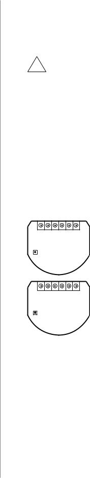
S1 - terminal for 1st switch (has the function of |
S1 S2 L L Q N |
activating the learning mode) |
B SINGLE
SWITCH 2
FGS-213
S1 S2 Q2 L Q1 N
B DOUBLE
SWITCH 2
FGS-223
S2 - terminal for 2nd switch L - terminal for live lead
Q/Q1 - output terminal of the 1st channel
Q2 - output terminal of the 2nd channel (only Double Switch 2)
N - terminal for neutral lead
B - service button (used to add/remove the device and navigate the menu)
Tips for arranging the antenna:
•Locate the antenna as far from metal elements as possible (connecting wires, bracket rings, etc.) in order to prevent interferences,
•Metal surfaces in the direct vicinity of the antenna (e.g. flush mounted metal boxes, metal door frames) may impair signal reception!
•Do not cut or shorten the antenna - its length is perfectly matched to the band in which the system operates.
•Make sure no part of the antenna sticks out of the wall switch box.
Installation

Installation of the Switch 2:
1.Switch off the mains voltage (disable the fuse).
2.Open the wall switch box.
3.Connect with one of following the diagrams for appropriate device:
single wall switch: |
double wall switch: |
|||||||||||||
L |
|
L |
|
|||||||||||
N |
|
|
|
N |
|
|
|
|||||||
|
|
|
|
|
||||||||||
|
|
|
|
|
|
|
|
|
|
|
|
|
|
|
|
|
|
|
|
|
|
|
|
|
|
|
|
|
|
|
|
|
|
|
|
|
|
|
|
|
|
|
|
|
|
|
|
|
|
|
|
|
|
|
|
|
|
|
|
|
|
|
|
|
|
|
|
|
|
|
|
|
|
|
|
|
|
|
|
|
|
|
|
|
|
|
|
|
|
|
|
|
|
|
|
|
|
|
|
|
|
|
|
|
|
|
|
|
|
|
|
|
|
|
|
|
|
|
|
|
|
|
|
|
|
|
|
|
|
|
|
|
|
|
|
|
|
|
|
|
|
|
|
|
|
|
|
|
|
|
|
|
|
|
|
|
|
|
|
|
|
|
|
|
|
|
|
|
|
|
|
|
|
|
|
|
|
|
|
|
|
|
|
|
|
|
|
|
|
|
|
|
S1 S2 L L Q N |
|
|
|
|
|
|
S1 S2 L L Q N |
|
|
|
|||||||||||||||||||||||
B SINGLE |
|
B SINGLE |
|||||||||||||||||||||||||||||||||||
|
|
|
|
|
|
|
SWITCH 2 |
|
|
|
|
|
|
|
SWITCH 2 |
||||||||||||||||||||||
|
|
|
|
|
|
|
FGS-213 |
|
|
|
|
|
|
|
FGS-213 |
||||||||||||||||||||||
|
|
|
|
|
|
Wiring diagrams - Single Switch 2 |
|||||||||||||||||||||||||||||||
single wall switch: |
double wall switch: |
||||||||||||||||||||||||||||||||||||
L |
|
L |
|
||||||||||||||||||||||||||||||||||
N |
|
|
|
|
|
N |
|
|
|
|
|
|
|||||||||||||||||||||||||
|
|
|
|
|
|
|
|
|
|||||||||||||||||||||||||||||
|
|
|
|
|
|
|
|
|
|
|
|
|
|
|
|
|
|
|
|
|
|
|
|
|
|
|
|
|
|
|
|
|
|
|
|
|
|
|
|
|
|
|
|
|
|
|
|
|
|
|
|
|
|
|
|
|
|
|
|
|
|
|
|
|
|
|
|
|
|
|
|
|
|
|
|
|
|
|
|
|
|
|
|
|
|
|
|
|
|
|
|
|
|
|
|
|
|
|
|
|
|
|
|
|
|
|
|
|
|
|
|
|
|
|
|
|
|
|
|
|
|
|
|
|
|
|
|
|
|
|
|
|
|
|
|
|
|
|
|
|
|
|
|
|
|
|
|
|
|
|
|
|
|
|
|
|
|
|
|
|
|
|
|
|
|
|
|
|
|
|
|
|
|
|
|
|
|
|
|
|
|
|
|
|
|
|
|
|
|
|
|
|
|
|
|
|
|
|
|
|
|
|
|
|
|
|
|
|
|
|
|
|
|
|
|
|
|
|
|
|
|
|
|
|
|
|
|
|
|
|
|
|
|
|
|
|
|
|
|
|
|
|
|
|
|
|
|
|
|
|
|
|
|
|
|
|
|
|
|
|
|
|
|
|
|
|
|
|
|
|
|
|
|
|
|
|
|
|
|
|
|
|
|
|
|
|
|
|
|
|
|
|
|
|
|
|
|
S1 S2Q2 L Q1 N |
|
|
|
S1 S2Q2 L Q1 N |
|
||||||||||||||||
B DOUBLE |
|
B DOUBLE |
|
|||||||||||||||||||
|
|
|
SWITCH 2 |
|
|
|
|
|
|
SWITCH 2 |
|
|||||||||||
|
|
|
FGS-223 |
|
|
|
|
|
|
FGS-223 |
|
|||||||||||
Wiring diagrams - Double Switch 2
4.After verifying correctness of the connection switch on the mains voltage.
5.Add the device to the Z-Wave network (see “Adding/removing the device” on page 8).
6.Turn off the mains voltage, then arrange the device and its antenna in a wall switch box.
7.Close the wall switch box and turn on the mains voltage.
7
i NOTE
Switch connected to the S1 terminal is a master switch. It activates the basic functionality of the device (turning the first load on/off) and activates the learning mode (adding/removing).
The switch connected to the S2 ter-
minal |
turns |
on/of |
||
the |
second |
load |
in |
|
Double |
Switch |
2, |
||
but |
is |
optional |
in |
|
Single |
Switch 2 and |
|||
pushing it will not affect the status of the device.
i NOTE
After switching on the mains voltage LED indicator will signal Z-Wave network inclusion state with a colour:
GREEN - device added RED - device not added
Installation

8
i NOTE
In case of problems with adding/removing using S1 switch, use B-button instead (located on the housing)
!CAUTION
While adding the Switch 2 to the network with connected toggle switch, ensure that switch contact is open (off). Otherwise it will prevent adding/ removing the device to/from the network.
i NOTE
The device will try to add itself for 4 minutes after pressing the switch 3 times.
i NOTE
Removing the Switch 2 from the Z-Wave network restores all the default parameters of the device, but does not reset power metering data.
i NOTE
Adding in security mode must be performed up to 2 meters from the controller.
#4: Adding/removing the device
Adding (Inclusion) - Z-Wave device learning mode, allowing to add the device to existing Z-Wave network.
To add the device to the Z-Wave network:
1.Place the Switch 2 within the direct range of your Z-Wave controller.
2.Identify the S1 switch.
3.Set the main controller in (security/non-security) add mode (see the controller’s manual).
4.Quickly, three times press the S1 switch.
5.Wait for the adding process to end.
6.Successful adding will be confirmed by the Z-Wave controller’s message.
Removing (Exclusion) - Z-Wave device learning mode, allowing to remove the device from existing Z-Wave network.
To remove the device from the Z-Wave network:
1.Place the Switch 2 within the direct range of your Z-Wave controller.
2.Identify the S1 switch.
3.Set the main controller in remove mode (see the controller’s manual).
4.Quickly, three times press the S1 switch.
5.Wait for the removing process to end.
6.Successful removing will be confirmed by the Z-Wave controller’s message.
Adding/removing the device
Loading...