

Page 1
OPERATING
MANUAL
EN
FIBARO
ROLLER SHUTTER 3
FGR-223
CONTENTS
#1: Description and features 3
#2: Installation 4
#3: Adding the device 8
#4: Removing the device 9
#5: Positioning calibration 10
#6: Operating roller blinds 13
#7: Operating gate motors 14
#8: Menu 15
#9: Resetting to factory defaults 16
v1.0
#10: Power and energy consumption 17
#11: Associations 18
#12: Z-Wave range test 19
#13: Activating scenes 20
#14: Z-Wave specication 21
#15: Advanced parameters 24
#16: Specications 32
#17: Regulations 33
Page 2

2
Important safety information
Read this manual before attempting to install the device!
!
Failure to observe recommendations included in this manual
may be dangerous or cause a violation of the law. The manufacturer,
Fibar Group S.A. will not be held responsible for any loss or damage
resulting from not following the instructions of operating manual.
Danger of electrocution!
FIBARO Roller Shutter 3 is designed to operate in electrical
home installation. Faulty connection or use may result in re or electric shock.
All works on the device may be performed only by a qualied and
licensed electrician. Observe national regulations.
Even when the device is turned o, voltage may be present at its terminals. Any maintenance introducing changes into the conguration
of connections or the load must be always performed with disabled
fuse.
Caution
!
It is not recommended to operate all of the roller blinds simultaneously. For safety reasons, at least one roller blind should be controlled independently, providing safe escape route in case of emergency.
Page 3
#1: Description and features
FIBARO Roller Shutter 3 is a device designed to control roller blinds,
awnings, venetian blinds, gates and other single phase, AC powered
devices.
Roller Shutter 3 allows precise positioning of roller blinds or venetian
blind lamellas. The device is equipped with power and energy
monitoring. It allows to control connected devices either via the
Z-Wave network or via a switch connected directly to it.
3
Main features of FIBARO Roller Shutter 3:
• Compatible with any Z-Wave or Z-Wave+ Controller,
• Supports Z-Wave network Security Modes: S0 with AES-128
encryption and S2 Authenticated with PRNG-based encryption,
• To be installed with roller blind motors with electronic or
mechanical limit switches,
• Advanced microprocessor control,
• Active power and energy metering functionality,
• Works with various types of switches – momentary, toggle and
dedicated roller blind switches,
• To be installed in wall switch boxes.
FIBARO Roller Shutter 3 is a fully
compatible Z-Wave PLUS device.
NOTE
i
This device may be
used with all devices certied with
the Z-Wave Plus certicate and should be
compatible with such
devices produced by
other manufacturers.
All non-battery operated devices within
the network will act as
repeaters to increase
reliability of the network.
NOTE
i
The device is a Security Enabled Z-Wave
Plus product and a Security Enabled Z-Wave
Controller must be
used in order to fully
utilize the product.
DESCRIPTION AND FEATURES
Page 4
4
#2: Installation
Connecting the Roller Shutter 3 in a manner inconsistent
with this manual may cause risk to health, life or material
!
damage.
• Connect only in accordance with one of the diagrams,
• Do not connect DC powered motors, the device is dedicated to
operate AC powered electric motors,
• Do not connect the device to loads exceeding recommended
values,
• The device should be installed in a wall switch box compliant with
a relevant national safety standards and with depth no less than
60mm,
• Electrical switches used in installation should be compliant with the
relevant safety standards,
• Length of wires used to connect the control switch should not
exceed 20m,
• Connect roller blind motors with electronic or mechanical limit
switches only.
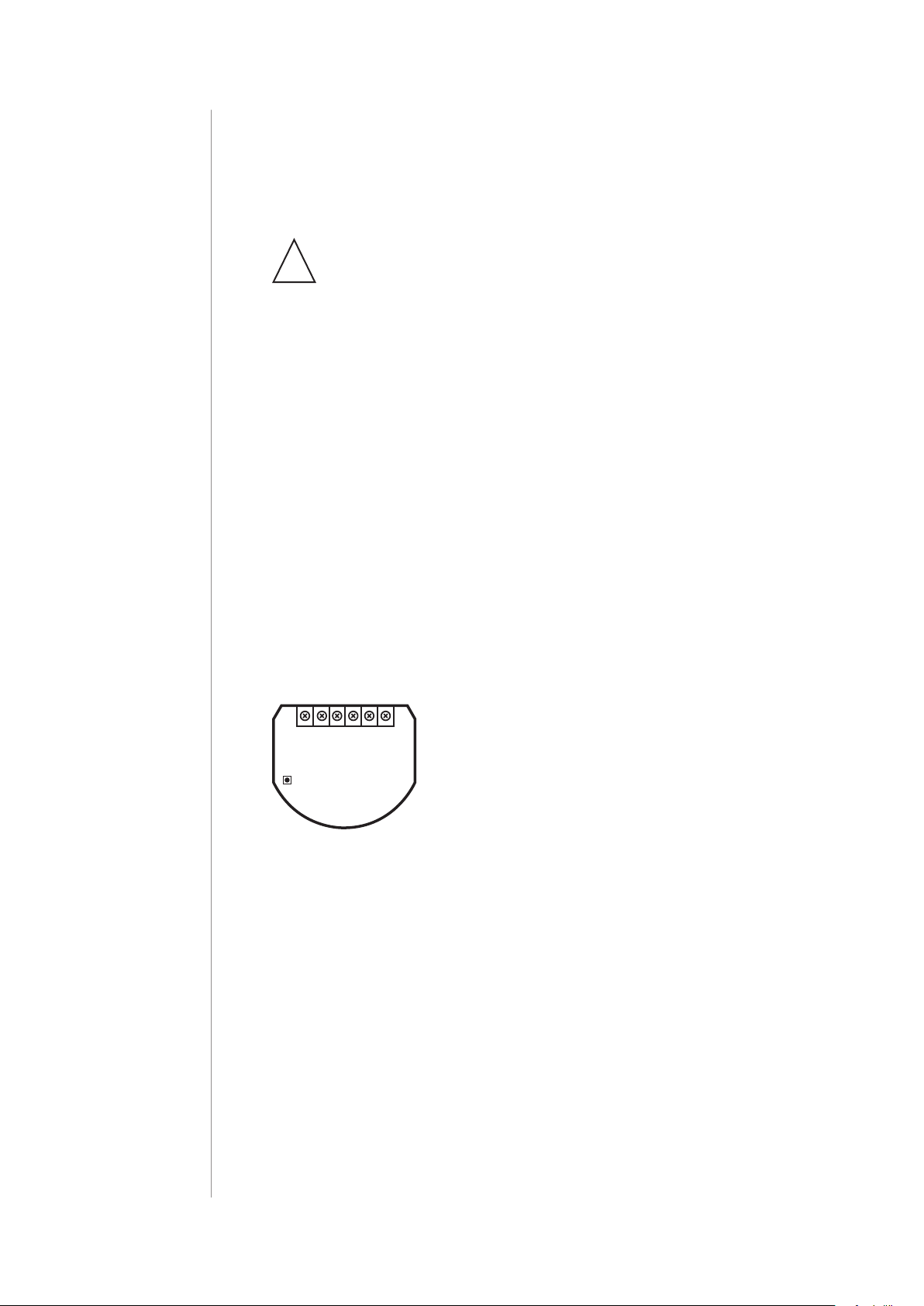
Notes for the diagrams:
S1 - terminal for 1st switch (used to add/remove
L NS1 S2 Q2
Q1
Roller
B
Shutter 3
Tips for arranging the antenna:
the device)
S2 - terminal for 2nd switch
Q2 - 2nd output terminal for shutter motor
Q1 - 1st output terminal for shutter motor
L - terminal for live lead
N - terminal for neutral lead
B - service button (used to add/remove the de-
vice and navigate the menu)
INSTALLATION
• Locate the antenna as far from metal elements as possible
(connecting wires, bracket rings, etc.) in order to prevent
interferences,
• Metal surfaces in the direct vicinity of the antenna (e.g. ush
mounted metal boxes, metal door frames) may impair signal
reception!
• Do not cut or shorten the antenna - its length is perfectly matched
to the band in which the system operates.
• Make sure no part of the antenna sticks out of the wall switch box.
Page 5
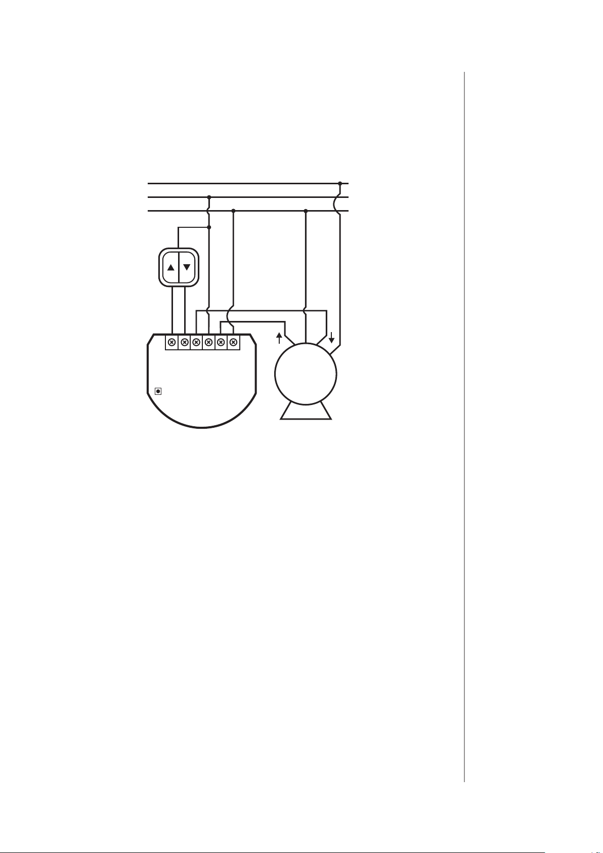
Installation with standard blinds:
PE
1. Switch o the mains voltage (disable the fuse).
2. Open the wall switch box.
3. Connect with the following the diagram:
L
N
N
5
L NS1 S2
Q2BQ1
Roller
M
Shutter 3
Wiring diagram - standard blinds
4. Verify if the device is connected correctly.
5. Arrange the device and its antenna in a wall switch box.
6. Close the wall switch box .
7. Switch on the mains voltage.
INSTALLATION
Page 6
6
PE
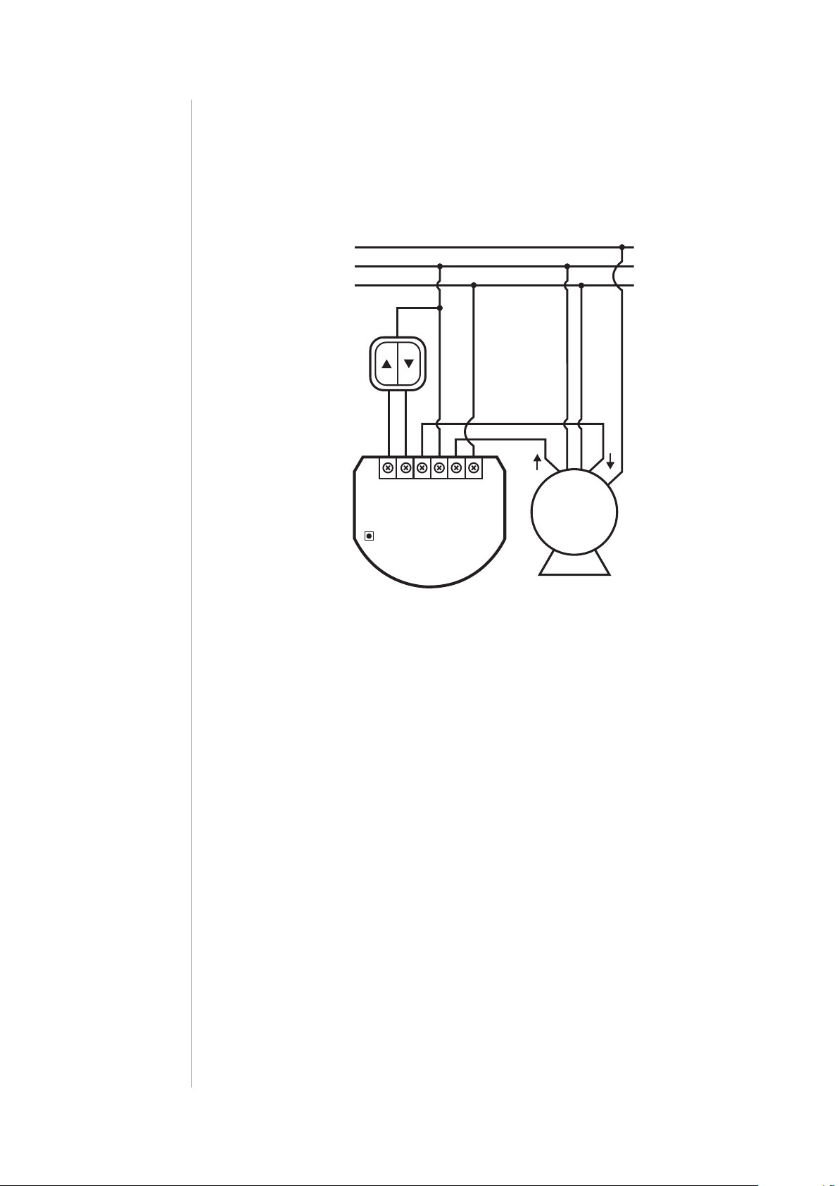
Installation with blinds with built-in driver:
1. Switch o the mains voltage (disable the fuse).
2. Open the wall switch box.
3. Connect with the following the diagram:
L
N
N
L
L NS1 S2
Q2BQ1
Roller
M
Shutter 3
Wiring diagram - blinds with built-in driver
4. Verify if the device is connected correctly.
5. Arrange the device and its antenna in a wall switch box.
6. Close the wall switch box .
7. Switch on the mains voltage.
INSTALLATION
Page 7
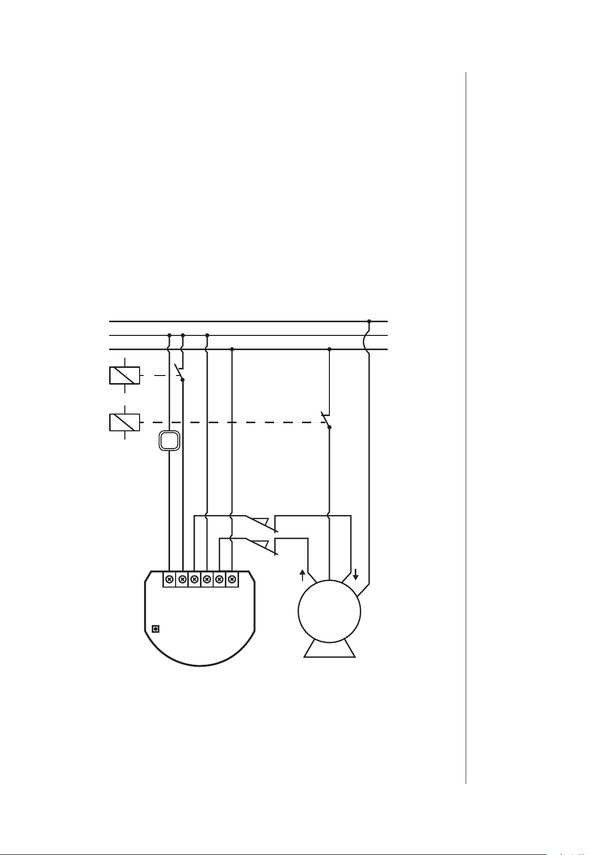
Installation with gate motors:
L
N
PE
• Installation of the gate driver may be performed only by certied
professionals.
• The motor must be equipped with the appropriate limit switches.
• It is recommended to connect a NC (normally closed) contact of
an IR barrier to S2 terminal. Opening the contact will stop the gate.
• In addition, it is recommended to connect an emergency stop
button to the motors neutral (N) wire. In emergency, pushing the
emergency stop button will cut the power and stop the gate.
1. Switch o the mains voltage (disable the fuse).
2. Open the installation box.
3. Connect with the following the diagram:
7
B
Shutter 3
sensor
NC
L NS1 S2 Q2 Q1
Roller
limit
switches
safety switch
NC
N
M
Wiring diagram - gate motors
4. Verify if the device is connected correctly.
5. Arrange the device and its antenna in the installation box.
6. Close the installation box.
7. Switch on the mains voltage.
INSTALLATION
Page 8

8
#3: Adding the device
Adding (Inclusion) - Z-Wave device learning mode, allowing to add
the device to existing Z-Wave network.
NOTE
i
In case of problems
with adding using the
S1 switch, use B-button instead (located
on the housing).
NOTE
i
SmartStart enabled products can be
added to SmartStart
enabled Z-Wave controller by scanning
the Z-Wave QR Code
present on the product. SmartStart product will be added
automatically within
10 minutes of being
switched on in the
network range.
To add the device to the Z-Wave network manually:
1. Power the device.
2. Identify the S1 switch.
3. Set the main controller in (Security/non-Security Mode) add mode
(see the controller’s manual).
4. Quickly, triple click the S1 switch.
5. If you are adding in Security S2 Authenticated, scan the DSK QR
code or input the 5-digit PIN code (label on the bottom of the
box).
6. Wait for the adding process to end.
7. Successful adding will be conrmed by the Z-Wave controller’s
message.
To add the device to the Z-Wave network using Smart Start:
1. Set the main controller in Security S2 Authenticated add mode
(see the controller’s manual).
2. Scan the DSK QR code or input the 5-digit PIN code (label on the
bottom of the box)
3. Power the device (turn on the mains voltage).
4. LED will start blinking yellow, wait for the adding process to end.
5. Successful adding will be conrmed by the Z-Wave controller’s
message.
ADDING THE DEVICE
Page 9

#4: Removing the device
9
Removing (Exclusion) - Z-Wave device learning mode, allowing to
remove the device from existing Z-Wave network.
Removing the device restores all the default parameters of the device, but does not reset power metering data.
To remove the device from the Z-Wave network:
1. Make sure the device is powered.
2. Identify the S1 switch.
3. Set the main controller in remove mode (see the controller’s
manual).
4. Quickly, triple click the S1 switch.
5. Wait for the removing process to end.
6. Successful removing will be conrmed by the Z-Wave controller’s
message.
NOTE
i
In case of problems
with removing using
the S1 switch, use
B-button instead (located on the housing).
NOTE
i
If parameter 40 enables scenes for triple
S1 click, disable it or
use B-button instead
to remove the device.
NOTE
i
If parameter 24 is set
to 1, use S2 switch instead to remove the
device.
REMOVING THE DEVICE
Page 10

10
#5: Positioning calibration
NOTE
i
If you notice the calibration process fail
(e.g. it does not start,
movement times are
really short or highly inaccurate), adjust
parameter 155 value
(e.g. reduce it by half).
Calibration is a process during which a device learns the position of
the limit switches and a motor characteristic.
Calibration is mandatory in order for the device to correctly recognize
a roller blind position.
The procedure consists of an automatic, full movement between the
limit switches (up, down, and up again).
Description:
– switch connected to the S1 terminal
– switch connected to the S2 terminal
Standard roller blind positioning
Calibration using connected momentary switch
1. Make sure:
• the device is supplied,
• momentary switch is connected to S1 and S2 terminals,
• the device added to the Z-Wave network,
• parameter 151 is set to 1 or 2.
2. Press and hold or switch for at least 3 seconds
3. Press and hold the same switch again for at least 3 seconds.
4. Press and hold the same switch again for at least 3 seconds.
5. The device will perform the calibration process, completing
full cycle – up, down and up again.
6. Test whether the positioning works correctly.
Calibration using the B-button
1. Make sure:
• the device is supplied,
• the device added to the Z-Wave network,
• parameter 151 is set to 1 or 2.
2. Press and hold the B-button.
3. Wait for the LED to glow white.
4. Quickly release and click the B-button again.
POSITIONING CALIBRATION
5. The device will perform the calibration process, completing
full cycle – up, down and up again
6. Test whether the positioning works correctly.
Page 11

Calibration using parameter
1. Make sure:
• the device is supplied,
• the device added to the Z-Wave network,
• parameter 151 is set to 1 or 2.
2. Set the parameter 150 value to 2
3. The device will perform the calibration process, completing
full cycle – up, down and up again
4. The parameter 150 value will be set to 1 after calibration nishes.
5. Test whether the positioning works correctly.
Slats positioning in venetian blinds mode
Calibration using connected momentary switch
11
1. Make sure:
• the device is supplied,
• momentary switch is connected to S1 and S2 terminals,
• the device added to the Z-Wave network,
• parameter 151 is set to 2,
• blinds are calibrated.
2. By default, time of transition between extreme positions is
set to 150 (1.5 seconds) in parameter 152.
3. Turn slats between extreme positions by holding or
switch:
• If after full cycle a blind starts moving up or down - decrease value of parameter 152,
• If after full cycle the slats does not reach end positions increase value of parameter 152,
4. Repeat previous step until satisfactory positioning is
achieved.
5. Test whether the positioning works correctly. Correctly congured slats should not force the blinds to move up or down.
POSITIONING CALIBRATION
Page 12

12
Roller blind with built-in driver positioning
1. Make sure:
• the device is supplied,
• momentary switch is connected to S1 and S2 terminals,
• the device added to the Z-Wave network,
• parameter 151 is set to 5 or 6.
2. By default, time of transition between extreme positions is
set to 600 (6 seconds) in parameters 155 and 156.
3. Move roller blinds between extreme positions by clicking
or switch:
• If roller blind stops before reaching top - increase value
of parameter 155,
• If roller blind does not stop after reaching top - decrease
value of parameter 155,
• If roller blind stops before reaching bottom - increase value of parameter 156,
• If roller blind does not stop after reaching bottom - decrease value of parameter 156,
4. Repeat previous step until satisfactory positioning is
achieved.
5. Test whether the positioning works correctly.
POSITIONING CALIBRATION
Page 13

#6: Operating roller blinds
13
The device allows for connecting switch to the S1 and S2 terminals.
These may be momentary (recommended) or toggle switches.
Switch buttons are responsible for managing the blind’s movement.
Description:
– switch connected to the S1 terminal
– switch connected to the S2 terminal
Using momentary switches:
Click switch – initiate up movement.
Click switch – initiate down movement.
If the blind is moving, clicking any button, will stop the movement.
Operating slats of venetian blinds
When operating venetian blinds it is possible to manage angle
of the slats.
Hold switch – initiate slats rotation up.
Hold switch – initiate slats rotation down.
NOTE
i
Momentary switch
After releasing the
switch a spring automatically pushes back
and disconnects the
switch)
Toggle switch
Operates as a two-position switch, it has no
spring that would set
one position of the
switch.
Using toggle switches:
Change switch state – initiate up movement.
Change switch state – initiate down movement.
Choosing a middle position stops the blinds.
OPERATING ROLLER BLINDS
Page 14

14
#7: Operating gate motors
NOTE
i
Momentary switch
After releasing the
switch a spring automatically pushes back
and disconnects the
switch)
The device allows to operate gate motors.
Gate motor should be connected to Q1 and Q2 terminals according
to installation diagram.
When operating gates a momentary switch may be connected to S1
terminal.
It is recommended to connect an IR barrier, an emergency stop button or any alarm mechanism to S2 terminal. Opening a contact in a
device connected to S2 terminal will always result in stopping a motor in current position.
Using momentary switch:
Click S1 switch – move gate in sequence:
OPEN -> STOP -> CLOSE -> STOP -> OPEN
Open S2 contact – stop movement
Automatic closing:
• After full opening – the gate will automatically start closing after
time specied in parameter 152,
• After opening S2 contacts – the gate will automatically start closing after time specied in parameter 154.
OPERATING GATE MOTORS
Page 15

#8: Menu
Menu allows to perform Z-Wave network actions. In order to use the
menu:
1. Switch o the mains voltage (disable the fuse).
2. Remove the device from the wall switch box.
3. Switch on the mains voltage.
4. Press and hold the B-button to enter the menu.
5. Wait for the LED to indicate the desired menu position with colour:
• WHITE - start calibration
• GREEN - reset energy consumption memory
• VIOLET - start range test
15
• YELLOW - reset the device
6. Quickly release and click the B-button again.
MENU
Page 16

16
#9: Resetting to factory defaults
NOTE
i
Resetting the device is
not the recommended way of removing
the device from the
Z-Wave network. Use
reset procedure only
if the primary controller is missing or
inoperable. Certain
device removal can
be achieved by the
procedure of removing described in “A dd ing the device” on
page 5.
Resetting the device to factory defaults:
Reset procedure allows to restore the device back to its factory settings, which means all information about the Z-Wave controller and
user conguration will be deleted.
1. Switch o the mains voltage (disable the fuse).
2. Remove the device from the wall switch box.
3. Switch on the mains voltage.
4. Press and hold the B-button to enter the menu.
5. Wait for the LED indicator to glow yellow.
6. Quickly release and click the B-button again.
7. After few seconds the device will be restarted, which is signalled
with the red LED indicator colour.
RESETTING TO FACTORY DEFAULTS
Page 17

#10: Power and energy consumption
17
The device allows for the active power and energy consumption monitoring. Data is sent to the main Z-Wave controller.
Measuring is carried out by the most advanced micro-controller technology, assuring maximum accuracy and precision (+/- 1% for loads
10W-1000W).
Electric active power - power that energy receiver is changing into a
work and heat. The unit of active power is Watt [W].
Electric energy - energy consumed by a device through a time
period. Consumers of electricity in households are billed by suppliers on the basis of active power used in given unit of time. Most
commonly measured in kilowatt-hour [kWh]. One kilowatt-hour is
equal to one kilowatt of power consumed over period of one hour,
1kWh = 1000Wh.
Resetting consumption memory:
The device allows to erase stored consumption data in three ways:
a) Using functionality of a Z-Wave controller (see the controller’s
manual).
b) Manually clearing the data using the following procedure:
NOTE
i
Power measurement
can contain mains
voltage uctuations
within +/- 10%.
CAUTION
!
The device stores periodically (every hour)
the consumption data
in the device memory. Disconnecting
the module from the
power supply will not
erase stored energy
consumption data.
1. Switch o the mains voltage (disable the fuse).
2. Remove the device from the wall switch box.
3. Switch on the mains voltage.
4. Press and hold the B-button to enter the menu.
5. Wait for the visual LED indicator to glow green.
6. Quickly release and click the B-button again.
7. Energy consumption memory will be erased.
c) By resetting the device (see “Operating the device” on page 13).
POWER AND ENERGY CONSUMPTION
Page 18

18
#11: Associations
Association (linking devices) - direct control of other devices within
the Z-Wave system network e.g. Dimmer, Relay Switch, Roller Shutter
or scene (may be controlled only through a Z-Wave controller).
The device provides the association of 3 groups:
1st association group – “Lifeline” reports the device status and al-
lows for assigning single device only (main controller by default).
2nd association group – “Roller Shutter” is assigned to shutter position control – UP/DOWN (uses Switch Multilevel command class).
3rd association group – “Slats” is assigned to slats position control
– UP/DOWN (uses Switch Multilevel command class).
The device in 2nd and 3rd group allows to control 5 regular or multichannel devices per an association group, with the exception of
“LifeLine” that is reserved solely for the controller and hence only 1
node can be assigned.
To add an association (using the Home Center controller):
1. Go to the device options by clicking the icon:
2. Select the „Advanced” tab.
3. Click the “Setting Association” button.
4. Specify to which group and what devices are to be associated.
5. Save the changes.
6. Wait for the conguration process to end.
Assocation groups mapping:
Root Endpoint
Association Group 2 Endpoint 1 Association Group 2
Association Group 3 Endpoint 2 Association Group 2
Association Group in
Endpoint
ASSOCIATIONS
Page 19

#12: Z-Wave range test
19
The device has a built in Z-Wave network main controller’s
range tester.
Follow the below instructions to test the main controller’s range:
1. Switch o the mains voltage (disable the fuse).
2. Remove the device from the wall switch box.
3. Switch on the mains voltage.
4. Press and hold the B-button to enter the menu.
5. Wait for the visual LED indicator to glow violet.
6. Quickly release and click the B-button again.
7. Visual indicator will indicate the Z-Wave network’s range (range
signalling modes described below).
8. To exit Z-Wave range test, click the B-button.
Z-Wave range tester signalling modes:
Visual indicator pulsing green - the device attempts to establish a
direct communication with the main controller. If a direct communication attempt fails, the device will try to establish a routed communication, through other modules, which will be signalled by visual
indicator pulsing yellow.
Visual indicator glowing green - the device communicates with the
main controller directly.
CAUTION
!
To make Z-Wave range
test possible, the device must be added
to the Z-Wave controller. Testing may stress
the network, so it is
recommended to perform the test only in
special cases.
NOTE
i
Communication mode
of the device may
switch between direct
and one using routing, especially if the
device is on the limit
of the direct range.
Visual indicator pulsing yellow - the device tries to establish a routed communication with the main controller through other modules
(repeaters).
Visual indicator glowing yellow - the device communicates with
the main controller through the other modules. After 2 seconds the
device will retry to establish a direct communication with the main
controller, which will be signalled with visual indicator pulsing green.
Visual indicator pulsing violet - the device does communicate at the
maximum distance of the Z-Wave network. If connection proves successful it will be conrmed with a yellow glow. It’s not recommended
to use the device at the range limit.
Visual indicator glowing red - the device is not able to connect to
the main controller directly or through another Z-Wave network device (repeater).
ZWAVE RANGE TEST
Page 20

20
#13: Activating scenes
The device can activate scenes in the Z-Wave controller by sending
scene ID and attribute of a specic action using Central Scene Command Class.
By default scenes are not activated, set parameters 40 and 41 to enable scene activation for selected actions.
Switch Action Scene ID Attribute
Switch clicked once 1 Key Pressed 1 time
Switch clicked twice 1 Key Pressed 2 times
Switch clicked
thrice
to S1 terminal
Switch connected
to S2 terminal
Switch connected
* Not available for toggle switches.
Switch held* 1 Key Held Down
Switch released* 1 Key Released
Switch clicked once 2 Key Pressed 1 time
Switch clicked twice 2 Key Pressed 2 times
Switch clicked
thrice
Switch held* 2 Key Held Down
Switch released* 2 Key Released
1 Key Pressed 3 times
2 Key Pressed 3 times
ACTIVATING SCENES
Page 21

#14: Z-Wave specication
Endpoint 1:
Generic Device Class: GENERIC_TYPE_SWITCH_MULTILEVEL
Specic Device Class: SPECIFIC_TYPE_CLASS_B_MOTOR_CONTROL
Description: represents switch connected to the S1 terminal.
Endpoint 2:
Generic Device Class: GENERIC_TYPE_SWITCH_MULTILEVEL
Specic Device Class: SPECIFIC_TYPE_CLASS_B_MOTOR_CONTROL
Description: represents switch connected to the S2 terminal.
Switch Multilevel Command Class values refers to:
• 0x00 - fully close
21
• 0x63 - fully open
Supported Command Classes:
Command Class Version Secure
ZWAVEPLUS_INFO [0x5E] V2
SWITCH_MULTILEVEL [0x26] V4 YES
ASSOCIATION [0x85] V2 YES
MULTI_CHANNEL_ASSOCIATION [0x8E] V3 YES
ASSOCIATION_GRP_INFO [0x59] V2 YES
TRANSPORT_SERVICE [0x55] V2
VERSION [0x86] V2 YES
MANUFACTURER_SPECIFIC [0x72] V2 YES
DEVICE_RESET_LOCALLY [0x5A] V1 YES
POWERLEVEL [0x73] V1 YES
SECURITY [0x98] V1
SECURITY_2 [0x9F] V1
SUPERVISION [0x6C] V1
METER [0x32] V3 YES
CONFIGURATION [0x70] V1 YES
CRC_16_ENCAP [0x56] V1
NOTIFICATION [0x71] V8 YES
PROTECTION [0x75] V2 YES
MULTI_CHANNEL [0x60] V4 YES
CENTRAL_SCENE [0x5B] V3 YES
FIRMWARE_UPDATE_MD [0x7A] V4 YES
APPLICATION_STATUS [0x22] V1
BASIC [0x20] V1 YES
ZWAVE SPECIFICATION
Page 22

22
Multichannel Command Class:
Command Class Version Secure
Endpoint 1
ZWAVEPLUS_INFO [0x5E] V2
SWITCH_MULTILEVEL [0x26] V4 YES
ASSOCIATION [0x85] V2 YES
MULTI_CHANNEL_ASSOCIATION [0x8E] V3 YES
ASSOCIATION_GRP_INFO [0x59] V2 YES
SECURITY [0x98] V1
SECURITY_2 [0x9F] V1
SUPERVISION [0x6C] V1
METER [0x32]
NOTIFICATION [0x71] V8 YES
APPLICATION_STATUS [0x22] V1
Endpoint 2
ZWAVEPLUS_INFO [0x5E] V2
SWITCH_MULTILEVEL [0x26] V4 YES
ASSOCIATION [0x85] V2 YES
MULTI_CHANNEL_ASSOCIATION [0x8E] V3 YES
ASSOCIATION_GRP_INFO [0x59] V2 YES
SECURITY [0x98] V1
SECURITY_2 [0x9F] V1
SUPERVISION [0x6C] V1
APPLICATION_STATUS [0x22] V1
V3 YES
ZWAVE SPECIFICATION
Notication Command Class:
The device uses Notication Command Class to report dierent events
to the controller (“Lifeline” group).
Notication
Type
Power
Management
[0x08]
System
[0x09]
Over-current detected
[0x06]
System Hardware Failure
[0x03]
Event Event Parameters
Device overheat
[0x01]
Page 23

Protection CC:
Protection Command Class allows to prevent local or remote control of
the device.
Type of protection State Description
Unprotected - The device is not pro-
Local 0
Local 2
RF (remote) 0
RF (remote) 1
tected, and may be operated normally
via S1 or S2
No operation possible – S1 and S2
cannot change relay state, any other
functionality is available (menu)
Unprotected - The device accepts and
respond to all RF Commands
No RF control – command class Basic
and Switch Binary are rejected, every
other command class will be handled
23
Meter Command Class:
Same for Root, Endpoint 1 and Endpoint 2.
Meter Type Scale Rate Type Precision Size
Electric
[0x01]
Electric
[0x01]
Electric_kWh
[0x00]
Electric_W
[0x02]
Import
[0x01]
Import
[0x01]
2 4
1 2
ZWAVE SPECIFICATION
Page 24

24
#15: Advanced parameters
FIBARO Roller Shutter 3 allows to customize its operation to user’s
needs. The settings are available in the FIBARO interface as simple
options that may be chosen by selecting the appropriate box.
In order to congure the module (using the Home Center controller):
1. Go to the device options by clicking the icon:
2. Select the „Advanced” tab.
INPUT/OUTPUT CONFIGURATION
NOTE
i
If parameter 20 is set
to 1 (toggle switch),
change value of parameter 153 to 0 for
slats to work properly.
20. Switch type
This parameter denes as what type the device should treat the
switch connected to the S1 and S2 terminals.
This parameter is not relevant in gate operating modes (parameter
151 set to 3 or 4). In this case switch always works as a momentary
and has to be connected to S1 terminal.
Available settings: 0 – momentary switches
1 – toggle switches
2 – single, momentary switch (the switch
should be connected to S1 terminal)
Default setting: 2 Parameter size: 1 [byte]
24. Inputs orientation
This parameter allows reversing the operation of switches connected
to S1 and S2 without changing the wiring.
Available settings: 0 - default (S1 - 1st channel, S2 - 2nd channel)
1 - reversed (S1 - 2nd channel, S2 - 1st channel)
Default setting: 0 Parameter size: 1 [byte]
ADVANCED PARAMETERS
25. Outputs orientation
This parameter allows reversing the operation of Q1 and Q2 without
changing the wiring (in case of invalid motor connection) to ensure
proper operation.
Available settings: 0 - default (Q1 - 1st channel, Q2 - 2nd channel)
1 - reversed (Q1 - 2nd channel, Q2 - 1st channel)
Default setting: 0 Parameter size: 1 [byte]
Page 25

ALARM CONFIGURATION
25
30. Alarm conguration - 1st slot
This parameter determines to which alarm frames and how the device
should react. The parameters consist of 4 bytes, three most signicant
bytes are set according to the ocial Z-Wave protocol specication.
Available settings: 1B [MSB] - Notication Type
2B - Notication Status
3B - Event/State Parameters
4B [LSB] - action:
0 - no action
1 - open blinds
2 - close blinds
Default setting: [0x00, 0x00, 0x00, 0x00]
(disabled)
Parameter size: 4 [bytes]
31. Alarm conguration - 2nd slot (Water)
This parameter determines to which alarm frames and how the device
should react. The parameters consist of 4 bytes, three most signicant
bytes are set according to the ocial Z-Wave protocol specication.
NOTE
i
Alarm with lower
number has the higher priority, thus rst
alarm will override
other alarms with the
same type.
NOTE
i
Setting Notication
Value to 0xFF will result in launching the
action twice: when
alarm occurs and is
cancelled.
Available settings: 1B [MSB] - Notication Type
2B - Notication Status
3B - Event/State Parameters
4B [LSB] - action:
0 - no action
1 - open blinds
2 - close blinds
Default setting: [0x05, 0xFF, 0x00, 0x00]
(Water Alarm, any notication, no action)
Parameter size: 4 [bytes]
ADVANCED PARAMETERS
Page 26

26
32. Alarm conguration - 3rd slot (Smoke)
This parameter determines to which alarm frames and how the device
should react. The parameters consist of 4 bytes, three most signicant
bytes are set according to the ocial Z-Wave protocol specication.
Available settings: 1B [MSB] - Notication Type
2B - Notication Status
3B - Event/State Parameters
4B [LSB] - action:
0 - no action
1 - open blinds
2 - close blinds
Default setting: [0x01, 0xFF, 0x00, 0x00]
(Smoke Alarm, any notication, no action)
Parameter size: 4 [bytes]
33. Alarm conguration - 4th slot (CO)
This parameter determines to which alarm frames and how the device
should react. The parameters consist of 4 bytes, three most signicant
bytes are set according to the ocial Z-Wave protocol specication.
Available settings: 1B [MSB] - Notication Type
2B - Notication Status
3B - Event/State Parameters
4B [LSB] - action:
0 - no action
1 - open blinds
2 - close blinds
Default setting: [0x02, 0xFF, 0x00, 0x00]
(CO Alarm, any notication, no action)
Parameter size: 4 [bytes]
ADVANCED PARAMETERS
Page 27

34. Alarm conguration - 5th slot (Heat)
This parameter determines to which alarm frames and how the device
should react. The parameters consist of 4 bytes, three most signicant
bytes are set according to the ocial Z-Wave protocol specication.
Available settings: 1B [MSB] - Notication Type
2B - Notication Status
3B - Event/State Parameters
4B [LSB] - action:
0 - no action
1 - open blinds
2 - close blinds
Default setting: [0x04, 0xFF, 0x00, 0x00]
(Heat Alarm, any notication, no action)
Parameter size: 4 [bytes]
27
SCENE TIGGERING CONFIGURATION
40. S1 switch - scenes sent
This parameter determines which actions result in sending scene IDs
assigned to them.
Available settings: 1 - Key pressed 1 time
2 - Key pressed 2 times
4 - Key pressed 3 times
8 - Key hold down and key released
Default setting: 0 Parameter size: 1 [byte]
41. S2 switch - scenes sent
This parameter determines which actions result in sending scene IDs
assigned to them.
Available settings: 1 - Key pressed 1 time
2 - Key pressed 2 times
4 - Key pressed 3 times
8 - Key hold down and key released
Default setting: 0 Parameter size: 1 [byte]
NOTE
i
Parameter 40 values
may be combined,
e.g. 1+2=3 means that
scenes for single and
double click are sent.
NOTE
i
Enabling triple click
for S1 in parameter 40
disables the ability to
add/remove via S1.
NOTE
i
Parameter 41 values
may be combined,
e.g. 1+2=3 means that
scenes for single and
double click are sent.
ADVANCED PARAMETERS
Page 28

28
POWER AND ENERGY REPORTING CONFIGURATION
60. Measuring power consumed by the device itself
This parameter determines whether the power metering should include the amount of active power consumed by the device itself.
Available settings: 0 - function inactive
1 - function active
Default setting: 0 Parameter size: 1 [byte]
61. Power reports - on change
This parameter determines the minimum change in consumed power
that will result in sending new power report to the main controller.
For loads under 50W, the parameter is not relevant and reports are
sent every 5W change.
Power report are sent no often then every 30 seconds.
Available settings: 0 - reports are disabled
1-500 (1-500%) - change in power
Default setting: 15 (15%) Parameter size: 2 [bytes]
62. Power reports - periodic
This parameter determines in what time intervals the periodic power
reports are sent to the main controller
pend on power change (parameter 61).
Available settings: 0 - periodic reports are disabled
30-32400 (30-32400s) - report interval
Default setting: 3600 (1h) Parameter size: 2 [bytes]
65. Energy reports - on change
This parameter determines the minimum change in consumed energy that will result in sending new energy report to the main controller.
Available settings: 0 - reports are disabled
1-500 (0.01 - 5 kWh) - change in energy
Default setting: 10
66. Energy reports - periodic
(0.1 kWh)
. Periodic reports do not de-
Parameter size: 2 [bytes]
ADVANCED PARAMETERS
This parameter determines in what time intervals the periodic energy
reports are sent to the main controller
pend on energy change (parameter 65).
Available settings: 0 - periodic reports are disabled
30-32400 (30-32400s) - report interval
Default setting: 3600 (1h) Parameter size: 2 [bytes]
. Periodic reports do not de-
Page 29

ROLLER SHUTTER OPERATION CONFIGURATION
150. Force calibration
By setting this parameter to 2 the device enters the calibration mode.
The parameter relevant only if the device is set to work in positioning
mode (parameter 151 set to 1, 2 or 4).
Available settings: 0 - device is not calibrated
1 - device is calibrated
2 - force device calibration
Default setting: 0 Parameter size: 1 [byte]
151. Operating mode
This parameter allows adjusting operation according to the connected device.
Available settings: 1 – roller blind (with positioning)
2 – Venetian blind (with positioning)
29
3 – gate (without positioning)
4 – gate (with positioning)
5 – roller blind with built-in driver
6 – roller blind with built-in driver (impulse)
Default setting: 1 Parameter size: 1 [byte]
152. Venetian blind - time of full turn of the slats
For Venetian blinds (parameter 151 set to 2) the parameter determines time of full turn cycle of the slats.
For gates (parameter 151 set to 3 or 4) the parameter determines time
after which open gate will start closing automatically (if set to 0, gate
will not close).
The parameter is irrelevant for other modes.
Available settings: 0-90000 (0 - 900s, every 0.01s) - time of turn
Default setting: 150 (1.5s) Parameter size: 4 [bytes]
ADVANCED PARAMETERS
Page 30

30
NOTE
i
If parameter 20 is set
to 1 (toggle switch),
change value of parameter 153 to 0 for
slats to work properly.
153. Set slats back to previous position
For Venetian blinds (parameter 151 set to 2) the parameter determines
slats positioning in various situations.
The parameter is irrelevant for other modes.
Available settings: 0 – slats return to previously set position only in
case of the main controller operation.
1 – slats return to previously set position in case
of the main controller operation, momentary
switch operation, or when the limit switch is
reached.
2 – slats return to previously set position in
case of the main controller operation, momentary switch operation, when the limit switch is
reached or after receiving the Switch Multilevel
Stop control frame
Default setting: 1 Parameter size: 1 [byte]
154. Delay motor stop after reaching end switch
For blinds (parameter 151 set to 1, 2, 5 or 6) the parameter determines
the time after which the motor will be stopped after end switch contacts are closed.
For gates (parameter 151 set to 3 or 4) the parameter determines time
after which the gate will start closing automatically if S2 contacts are
opened (if set to 0, gate will not close).
Available settings: 0-600 (0 - 60s) - time
Default setting: 10
(1s)
Parameter size: 2 [bytes]
155. Motor operation detection
Power threshold to be interpreted as reaching a limit switch.
Available settings: 0 - reaching a limit switch will not be detected
1-255 (1-255W) - report interval
Default setting: 10(10W) Parameter size: 2 [bytes]
156. Time of up movement
This parameter determines the time needed for roller blinds to reach
the top
.
For modes with positioning value is set automatically during calibration, otherwise it must be set manually.
Available settings: 1-90000 (0.01 - 900.00s, every 0.01s) - move-
ment time
Default setting: 6000 (60s) Parameter size: 4 [bytes]
ADVANCED PARAMETERS
Page 31

157. Time of down movement
This parameter determines time needed for roller blinds to reach the
bottom
For modes with positioning value is set automatically during calibration, otherwise it must be set manually.
Available settings: 1-90000 (0.01 - 900.00s, every 0.01s) - move-
Default setting: 6000 (60s) Parameter size: 4 [bytes]
.
ment time
31
ADVANCED PARAMETERS
Page 32

32
#16: Specications
NOTE
i
Radio frequency of
individual device
must be same as your
Z-Wave controller.
Check information
on the box or consult
your dealer if you are
not sure.
Power supply:
Rated load current:
Supported motor type:
Required limit switches:
Power consumption:
Operating temperature:
Operating humidity:
Active element:
For installation in boxes:
Radio protocol:
Radio signal power:
Radio frequency:
Range:
100-240V~ 50/60 Hz
4.2A for lamps and resistive loads
1.7A for motors with compensated
power factor (inductive loads)
single-phase AC motors
electronic or mechanic
up to 0.8W
0-35°C
10-95%RH without condensation
micro-gap relay switch
Ø ≥ 50mm, depth ≥ 60mm
Z-Wave (500 series chip)
EIRP up to 6dBm
868.4 or 869.8 MHz EU;
908.4 or 916.0 MHz US;
921.4 or 919.8 MHz ANZ;
869.0 MHz RU;
up to 50m outdoors
up to 40m indoors
(depending on terrain and building
structure)
Dimensions (L x W x H):
Compliance with EU directives:
42.5 x 38.25 x 20.3 mm
RoHS 2011/65/EU
RED 2014/53/EU
SPECIFICATIONS
Page 33

#17: Regulations
This device complies with Part 15 of the FCC Rules
Operation is subject to the following two conditions:
1. This device may not cause harmful interference
2. This device must accept any interference received, including interference that may cause undesired operation. This equipment has been
tested and found to comply with the limits for a Class B digital device,
pursuant to part 15 of the FCC Rules. These limits are designed to provide reasonable protection against harmful interference in a residential installation. This equipment generates, uses and can radiate radio
frequency energy and, if not installed and used in accordance with the
instructions, may cause harmful interference to radio communications.
However, there is no guarantee that interference will not occur in a particular installation. If this equipment does cause harmful interference
to radio or television reception, which can be determined by turning
the equipment o and on, the user is encouraged to try to correct the
interference by one or more of the following measures:
• Reorient or relocate the receiving antenna.
• Increase the separation between the equipment and receiver.
• Connect the equipment into an outlet on a circuit dierent from
that to which the receiver is connected.
• Consult the dealer or an experienced radio/TV technician for help.
33
Changes and modications not expressly approved by the manufacturer or registrant of this equipment can void your authority to operate
this equipment under Federal Communications Commission’s rules.
Industry Canada (IC) Compliance Notice
This device complies with Industry Canada license-exempt RSSs. Operation is subject to the following two conditions: (1) this device may
not cause interference, and (2) this device must accept any interference, including interference that may cause undesired operation of the
device.
Cet appareil est conforme aux normes d’exemption de licence RSS d’Industry Canada. Son fonctionnement est soumis aux deux conditions
suivantes : (1) cet appareil ne doit pas causer d’interférence et (2) cet
appareil doit accepter toute interférence, notamment les interférences
qui peuvent aecter son fonctionnement.
Legal Notices
All information, including, but not limited to, information regarding the
features, functionality, and/or other product specication are subject
to change without notice. Fibaro reserves all rights to revise or update its products, software, or documentation without any obligation to
notify any individual or entity.
FIBARO and Fibar Group logo are trademarks of Fibar Group S.A. All
other brands and product names referred to herein are trademarks of
their respective holders.
REGULATIONS
Page 34

34
DGT Warning Statement
Article 12
Without permission, any company, rm or user shall not alter the frequency, increase the power, or change the characteristics and functions
of the original design of the certied lower power frequency electric
machinery.
Article 14
The application of low power frequency electric machineries shall not
aect the navigation safety nor interfere a legal communication, if an
interference is found, the service will be suspended until improvement
is made and the interference no longer exists.
第十二條
經型式認證合格之低功率射頻電機,非經許可,公司、商號或使用
者均不得擅自變更頻率、加大功率或變更原設計之特性及功能。
第十四條
低功率射頻電機之使用不得影響飛航安全及干擾合法通信;經發現
有干擾現象時,應立即停用,並改善至無干擾時方得繼續使用。
前項合法通信,指依電信法規定作業之無線電通信。
低功率射頻電機須忍受合法通信或工業、科學及醫療用電波輻射性
電機設備之干擾。
Declaration of conformity
Hereby, Fibar Group S.A. declares that the device is in compliance with the essential requirements and other relevant
provisions of Directive 2014/53/EU. The full text of the EU
declaration of conformity is available at the following internet address:
www.manuals.baro.com
WEEE Directive Compliance
Device labelled with this symbol should not be disposed with
other household wastes. It shall be handed over to the applicable collection point for the recycling of waste electrical and
electronic equipment.
REGULATIONS
 Loading...