

Page 1

Page 2

Dear Customer,
Thank you for selecting Fiat and congratulations on your choice of a Fiat Doblò.
We have written this handbook to help you get to know all your new Fiat Doblò features and use it in the best
possible way.
You should read it right through before taking the road for the first time.
You will find information, tips and important warnings regarding the driving of your vehicle to help you derive
the maximum from your Fiat Doblò’s technological features. You will find very valuable tips for your own safety,
the vehicle’s wellbeing and about how to protect the environment.
The enclosed Warranty Booklet lists the services that Fiat offers to its Customers:
• the Warranty Certificate with terms and conditions for maintaining its validity
• the range of additional services available to Fiat Customers.
Best regards and good motoring!
This Owner Handbook describes all Fiat Doblò versions. As a consequence, you should consider only the
information which is related to the engine and bodywork version of the vehicle you purchased.
1
Page 3
VERY IMPORTANT!
REFUELLING
Petrol engines: only refuel with unleaded petrol with octane rating (RON) not less than 95.
Diesel engines: refuel diesel engine vehicles with diesel fuel for motor vehicles meeting EN590 European Spec-
K
STARTING THE ENGINE
PARKING ON FLAMMABLE MATERIAL
ifications only.
The use of other products or mixtures may irreparably damage the engine with invalidation of the warranty due
to the damage caused.
Make sure that the handbrake is up. Put the gearbox in neutral. Press the clutch pedal fully without pressing
the accelerator. At this point:
petrol engines: turn the ignition key to AVV and release it as soon as the engine starts.
diesel engines: turn the ignition key to MAR and wait for the warning lights ¢ (Y) and m to go off; turn
the ignition key to AVV and release it as soon as the engine has started.
The catalytic converter develops high temperature during operation, Do not park the vehicle on grass, dry
leaves, pine needles or other flammable material: fire hazard.
RESPECTING THE ENVIRONMENT
The vehicle is equipped with a system for continuously monitoring emissions control system components to
ensure environmental-friendlier running.
U
2
Page 4
ELECTRICAL ACCESSORIES
If you want to add electrically powered accessories after buying the vehicle (with the risk of gradually draining
the battery) visit a Fiat Dealership. They will evaluate the overall electrical intake and check whether the electric system can support the required load.
쇵
CODE card
Keep the code card in a safe place, not in the vehicle. You should always keep the electronic card code written on the CODE card with you.
SCHEDULED SERVICING
Correct maintenance will preserve your vehicle’s performance, safety features, environmental-friendliness and
low running costs in time.
THE OWNER HANDBOOK CONTAINS …
…information, tips and important warnings regarding the safe, correct driving of your vehicle, and its maintenance. Pay particular attention to the symbols "(personal safety) #(environmental protection) â(the vehicle wellbeing).
3
Page 5

WELCOME ABOARD Fiat Doblò
Fiat Doblò is a compact vehicle with an original bodyline, designed to offer great driving comfort, ensure safe-
ty and be a real friend to the environment.
Everything, from its new engines to its safety devices, from its improved comfort for driver and passengers alike
to its practical solutions, contributes to make you appreciate your Fiat Doblò’s personality.
And you will realise it later when you discover that its driving style and performance goes hand in hand with
new manufacturing processes that help cut running costs.
The Fiat Doblò, for example, needs to be taken in for its first servicing after 20,000 km.
4
Page 6
THE SIGNS TO HELP YOU DRIVE CORRECTLY
The signs you see on this page are very important. They highlight those parts of the handbook where, more than
anywhere else, you should stop for a minute and read carefully.
As you can see, each sign has a different symbol to make it immediately clear and easy to identify the subjects in
the different areas:
Personal safety.
Important: total or partial failure to
follow these instructions can place driver, passengers or others in serious
danger.
Protecting the environment.
This shows you the correct procedures to follow to ensure that the vehicle does not harm the environment.
Vehicle well-being.
Important. Total or partial failure to
follow these instructions will result in
the risk of serious damage to the vehicle and may invalidate the warranty
as well.
5
Page 7
GGEETTTTIINNGGTTOOKKNNOOW
WYYOOUURRVVEEHHIICCCLLEE
SYMBOLS
Special coloured labels have been attached near or actually on some of the
components of your Fiat Doblò. These
labels bear symbols that remind you of
the precautions to be taken as regards
that particular component.
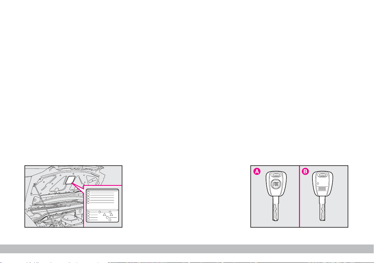
Plate A-fig. 1 summarising the symbols used can be found under the bonnet.
THE FIAT CODE
SYSTEM
To further protect your vehicle from
theft, it has been fitted with an engine
immobilising system (Fiat CODE system) which is automatically activated
when the ignition key is removed.
An electronic device, in fact, is fitted
in each ignition key grip. The device
transmits a radio-frequency signal
when the engine is started through a
special aerial built into the ignition
switch. The modulate signal, which
changes each time the engine is started, is the password by means of which
the control unit recognises the key
and enables to start the engine.
F0A0001b
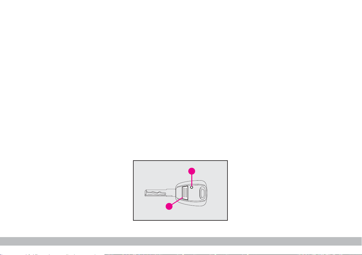
KEYS fig. 2
The following keys are provided with
the vehicle:
– two keys A when the vehicle is not
equipped with remote control;
– key A and key B when the vehicle
is equipped with door lock remote
control.
– Key A is the key that is used normally. It will:
– start the engine;
– lock/unlock front doors;
F0A0700b
fig. 1
6
fig. 2
GETTING TO KNOW YOUR VEHICLE
Page 8
– lock/unlock the rear doors or the
tailgate;
– lock/unlock the side doors, Cargo
versions only;
– deactivate the passenger’s airbag.
The key B, with a built-in remote
control, has the same functions as key
A in vehicles with door lock remote
control.
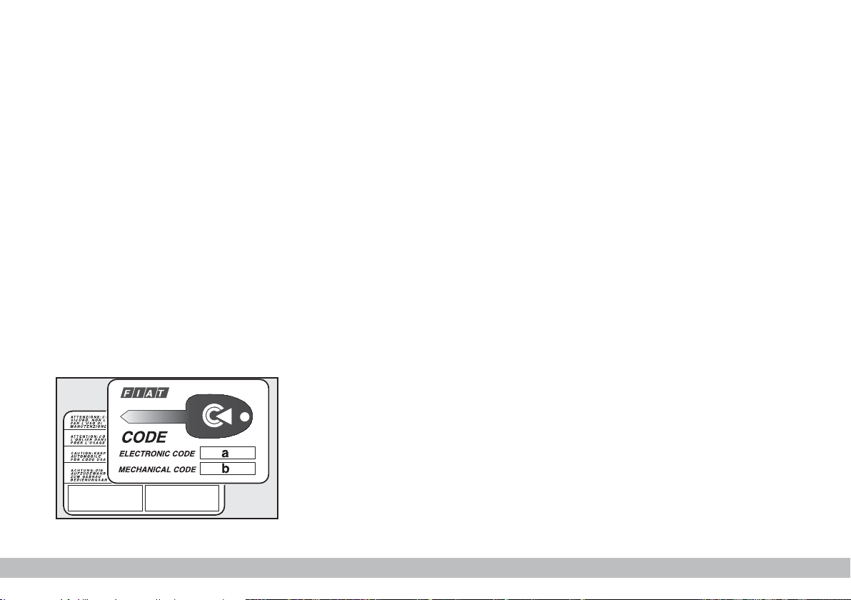
The CODE card fig. 3 is also supplied with the keys and bears the following:
a - the electronic code to be used for
emergency starting (see “Emergency
start-up” in section “In an emergency”);
fig. 3
b - the mechanical key code to be
given to the Fiat Dealership when
ordering duplicate keys.
Keep the CODE card in a safe place.
Make sure you have the electronic
code of the CODE card with you at all
times in the event you have to perform an emergency start-up.
OPERATION
Each time the ignition key is turned
to STOP, or PARK, the protection
system will automatically immobilise
the engine.
When the key is turned to MAR to
start the engine:
1) if the code is recognised the ¢
(Y) warning light on the instrument
panel will flash briefly; this means the
protection system has recognised the
key code and deactivates the immo-
F0A0003b
biliser, turn the key to AVV, and the
engine will start.
2) If the warning light ¢ (Y) stays
on, the code was not recognised. In
this case, turn the key to STOP and
then back to MAR. If the engine re-
mains immobilised, try with the other key provided.
If you are still unable to start the engine, use the emergency starting procedure (see “In an emergency”) and
take your vehicle to the nearest Fiat
Dealership.
When the vehicle is travelling and the
key is at MAR:
1) if the warning light ¢(Y) comes
on while the vehicle is moving, this
means that the system is running a selftest (e.g. due to a voltage drop).
2) if the warning light ¢ (Y) flash-
es, the vehicle is not protected by the
engine immobiliser. Contact a Fiat
Dealership immediately and get them
to store the codes of all the keys in the
memory.
IMPORTANT The electronic components inside the key may be damaged if the key is subjected to sharp
knocks.
IMPORTANT Each key provided
with the vehicle has its own code, different from all the others, which must
be stored in the memory of the system control unit.
GETTING TO KNOW YOUR VEHICLE
7
Page 9
DUPLICATE KEYS
A
B
When additional keys are required,
go to your Fiat Dealership taking all
the keys in your possession and the
CODE card with you. The Fiat Deal-
ership will store the old and new keys
(up to eight) in the system. The Fiat
Dealership may ask you to demonstrate that you own the vehicle.
The codes of any keys that are not
handed over when the new storage
procedure is carried out will be deleted from the memory to prevent any
lost or stolen keys being used to start
the vehicle.
All the keys and the CODE card
must be handed over to the new owner when selling the vehicle.
DOOR LOCK
REMOTE CONTROL
The remote control is built into the
ignition key. Press button A-fig. 4 to
lock and unlock the doors.
Press button A to operate the system. LED B (where required) will flash
while the transmitter is sending the
code to the receiver.
The ceiling light and map-reading light
will come on for the predefined time
when the doors are unlocked with the
remote control.
For ordering additional remote controls or replacing the batteries, see the
following paragraphs.
IMPORTANT The remote control
system frequency can be disturbed by
significant radio transmissions outside
the vehicle (e.g: mobile phones, HAM
radio systems, etc.) that could cause
remote control malfunctioning.
Ministerial homologation
In accordance with the legislation
covering radio frequencies in force in
each country, we should like to point
out that:
– the market-specific homologation
numbers are listed in the paragraph
“Radio-frequency remote controls” in
section “Technical specifications”.
– for markets requiring transmitter
marking, the transmitter code is print-
F0A0004b
ed on the remote control.
8
GETTING TO KNOW YOUR VEHICLE
fig. 4
Page 10
ORDERING ADDITIONAL
B
C
A
REMOTE CONTROLS
The system can recognise up to 8
keys with incorporated remote control.
If additional remote controls are required for any reasons, go to a Fiat
Dealership, taking all the keys you
own and the CODE card with you.
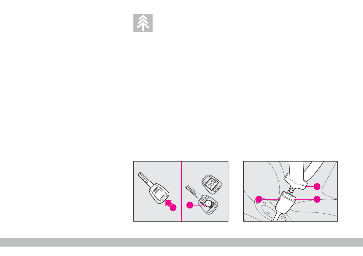
REPLACING THE BATTERIES
Change the batteries (using spare
batteries of the same kind) as follows.
Open the plastic case by inserting a
screwdriver in recess A-fig. 5. Insert
new batteries B respecting the polarity and close the plastic case.
Used batteries are
harmful to the environment. They should be dis-
posed of as specified by law in the
special containers provided, or
take them to a Fiat Dealership,
which will deal with their disposal.
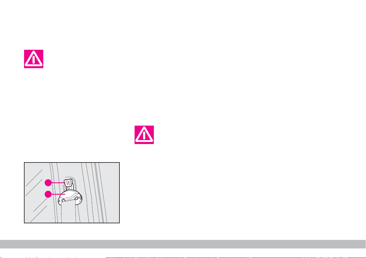
SEAT BELTS
USING THE SEAT BELTS
The belt should be worn keeping the
chest straight and rested against the
seat back.
Take hold of the tongue A-fig. 6. Insert it into the buckle B, until you hear
it clicks.
At removal, if it jams, let it rewind for
a short stretch, then pull it out again
without jerking.
F0A0005b
B
A
fig. 5
fig. 6
GETTING TO KNOW YOUR VEHICLE
F0A0006b
9
Page 11
Never press button C
when travelling.
To unfasten the seat belts, press button C. Guide the seat belt with your
hand while it is rewinding, to prevent
it from twisting.
Through the reel, the belt automatically adapts to the body of the passenger wearing it, allowing freedom of
movement.
When the vehicle is parked on a
steep slope the reel mechanism may
block; this is normal. The reel mechanism prevents the webbing coming
out when it is jerked or if the vehicle
brakes sharply, as in a collision or
when cornering at high speed.
Every rear seat (where provided) is
fitted with inertial seat belts with three
anchor points and reel.
IMPORTANT Before fastening the
seat belts make sure the seat is properly anchored.
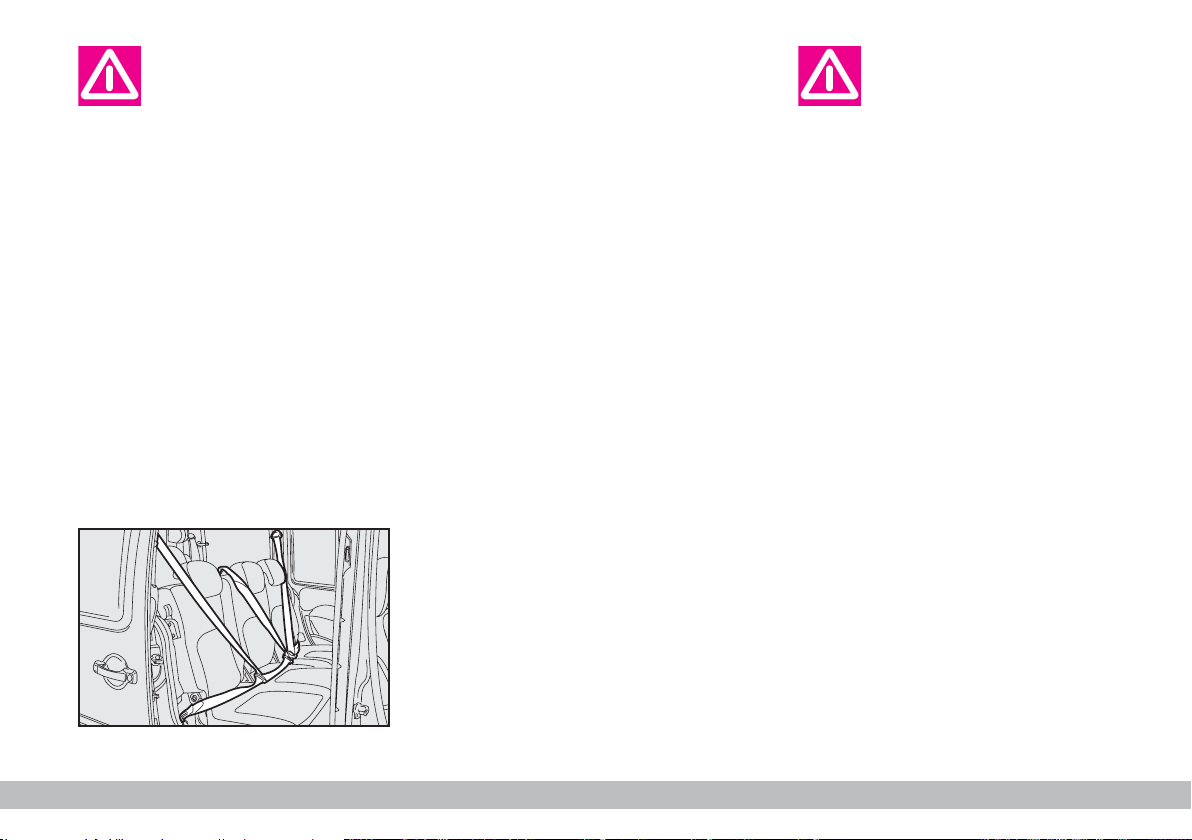
7-seat versions
In the 7-seat versions, every rear seat
(second and third row) is fitted with
seat belts with three anchor points
and reel fig. 7.
F0A0402b
Remember that in the
case of a violent collision,
back seat passengers not
wearing seat belts also represent
a serious danger to the passengers in the front seats.
fig. 7
10
GETTING TO KNOW YOUR VEHICLE
Page 12
ADJUSTING THE FRONT
B
A
SEAT BELT HEIGHT
Make the height adjustment when the vehicle is
stationary.
Always adjust the height of the seat
belt to fit the person wearing it. This
could greatly reduce the risk of injury
in the case of collision.
The belt is adjusted properly when
the webbing passes approximately
halfway between the edge of the
shoulder and the neck. Four height adjustments are possible.
To raise the belt: raise loop A-fig.
8 to the required position.
To lower the belt: press knob B,
and at the same time move loop A to
the required position.
Check that the seat belt is locked in
position by pushing down on loop A
without pressing knob B.
After you have made the
adjustment, always make
sure that the loop is at-
tached firmly in one of the fixed
positions and cannot move. To
do this, with the button released,
exert a further pressure to allow
F0A0008b
the anchoring device to catch if
release did not take place at one
of the preset positions.
PRETENSIONERS
The Fiat Doblò (with passenger's air
bag ) is fitted with pretensioners on
the front side seats to improve the
protection provided by the seat belts.
These devices “feel”, that a violent collision is in progress via a sensor and
pull back a few inches of webbing. In
this way the pretensioner ensures that
the belt is adhering perfectly to the
body before the belt begins to hold
back the wearer.
The seat belt locks to indicate that
the device has intervened; the seat belt
cannot be drawn back up even when
guiding it manually.
IMPORTANT The pretensioner
will give maximum protection when
the seat belt adheres snugly to the
wearer’s chest and hips.
fig. 8
GETTING TO KNOW YOUR VEHICLE
11
Page 13
Some smoke may be produced when
the pretensioners are fired. This
smoke is harmless and does not indicate the principle of a fire.
The pretensioner does not require
any maintenance or greasing. Anything
that modifies its original conditions invalidates its efficiency. If due to unusual
natural events (floods, seas storm,
etc.) the device has been affected by
water and mud, it must necessarily be
replaced.
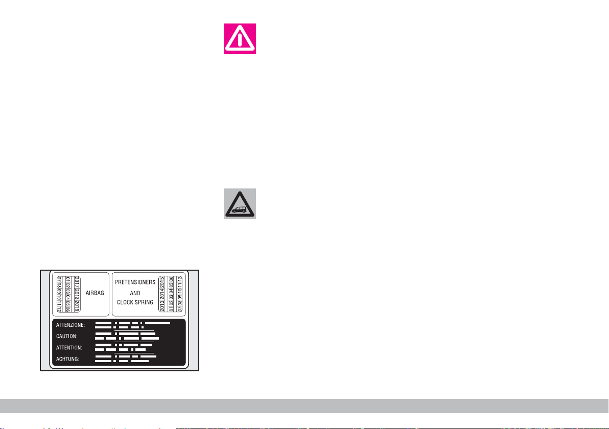
The pretensioner can
only be used once. Following a collision that has
triggered it, have it replaced at
a Fiat Dealership. Pretensioner
validity is written on the plate, fig.
9, set inside the glove box. Have
pretensioners replaced at a Fiat
Dealership as this date approaches.
Operations involving
banging, vibrations or
heating (exceeding 100°C
for a maximum of 6 hours) in the
area around the pretensioner
may trigger or damage the device. Vibrations from rough road
surfaces or accidental jolting
caused by mounting pavements
F0A0421b
etc. do not have any effect on the
pretensioner. If, however, you
need any assistance, go to a Fiat
Dealership.
Load limiting device
This device reduces the load with is
normally exerted by the seat belts on
the passenger’s shoulder and chest in
a collision. It increases protection by
preventing the micro traumas which
are inevitable in road accidents (also
in vehicles with airbags). The device
is built into the belt reel.
fig. 9
12
GETTING TO KNOW YOUR VEHICLE
Page 14
GENERAL INSTRUCTIONS
FOR USING
THE SEAT BELTS
The driver is responsible for respecting and enforcing the local rules
and laws regarding the use of seat
belts.
Always fasten the seat belts before
starting.
For maximum safety,
keep the back of your seat
upright, lean back into it
and make sure the seat belt fits
closely across your chest and
hips. Always fasten seat belts, in
front and rear seats! Travelling
without seat belts increases the
risk of severe and fatal injury in
the event of a crash.
Under no circumstances
should the components of
seat belts and preten-
sioners be tampered with or removed. Any interventions should
be carried out by qualified and
authorised personnel. Always
contact a Fiat Dealership.
fig. 10
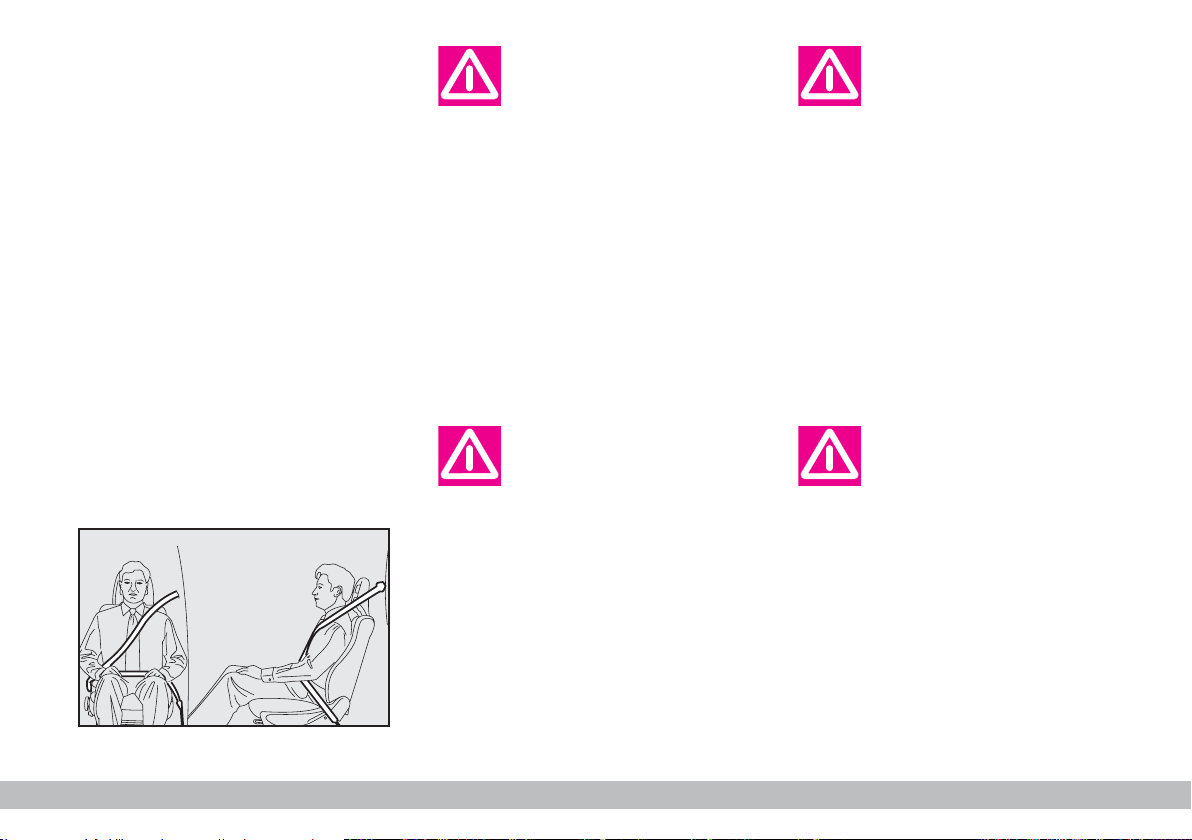
The webbing must not
be twisted. The upper
section must pass across
the shoulder and chest diagonally. The lower part must fit closely across the passenger’s hips, fig.
F0A0010b
10, and not the abdomen, to prevent them from sliding forwards.
Do not use clips, fasteners etc. to
prevent the belt adhering to the
passenger’s body.
If the belt has been subjected to heavy stress, for
example after an acci-
dent, it should be changed completely together with the anchors, anchor fastening screws
and the pretensioners. In fact,
even if the belt has no visible defects, it could have lost its resilience.
GETTING TO KNOW YOUR VEHICLE
13
Page 15
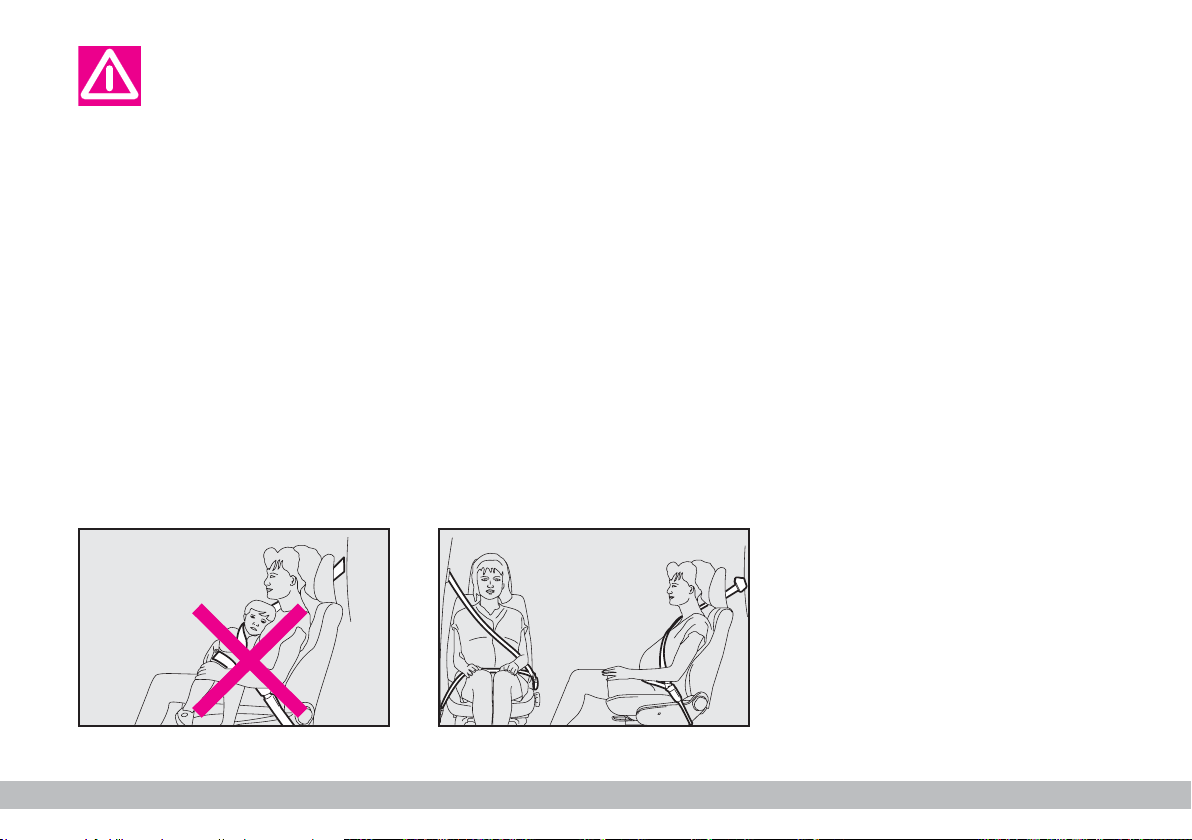
Never travel with a child
sitting on the passenger’s
lap with a single belt to
protect them both, fig. 11. Do not
fasten other objects to the body.
Seat belts must also be worn by expectant mothers: the risk of injury in
the case of accident is much greater
for them and their unborn child too
if they do not have a seat belt on. Of
course they must position the lower
part of the belt very low down so that
it passes under the abdomen fig. 12.
F0A0011b
HOW TO KEEP THE SEAT
BELTS IN PROPER WORKING
ORDER AT ALL TIMES
1) When wearing the seat belts, al-
ways ensure they are not twisted and
are free to wind in and out.
2) Following a serious accident, replace the belt being worn at that time,
even if it does not seem damaged. Always replace the seat belts if pretensioners have been activated.
3) When cleaning the belts, wash
them by hand with water and neutral
soap, rinse them and let them dry in
the shade. Do not use strong detergents, bleach, colouring or any other
chemical substance that could weaken
the belt fibres.
4) Do not allow the reel mechanisms
to get wet: they are only guaranteed
to work properly if they remain dry.
F0A0012b
5) Replace the seat belt when showing significant wear or cut signs.
fig. 11
14
fig. 12
GETTING TO KNOW YOUR VEHICLE
Page 16

TRANSPORTING CHILDREN SAFELY
SERIOUS DANGER: Never place cradle child’s seats not
facing the running direction on the front seat of vehicles
with passenger’s airbag, which during inflation could cause
serious injury, even mortal. You are advised to carry children always on
the rear seat, as this is the most protected position in the case of a crash.
In any case, child’ seats must absolutely not be fitted on the front seats
of vehicles with passenger’s airbag, which during inflation could cause
serious injury, even mortal, regardless of the seriousness of the crash
that triggered it. Children may be placed on the front seat of vehicles
fitted with passenger’s airbag deactivation. In this case, it is absolutely
necessary to check the warning light Fon the instrument panel to
make sure that deactivation has actually taken place (see paragraph
RONT AND SIDE AIRBAGS AT ITEMFRONT PASSENGER AIRBAG
F
senger’s seat shall be adjusted in the most backward position to prevent any contact between child’s seat and dashboard.
). The front pas-
For optimal protection in the event
of a crash, all passengers must be seated and wearing adequate restraint systems.
This is even more important for children.
This prescription is compulsory in all
EC countries according to EC Directive 2003/20/EC.
Compared with adults, their head is
proportionally larger and heavier than
the rest of the body, while the muscles and bone structure are not completely developed. Therefore, correct
restraint systems are necessary, other then adult seat belts.
GETTING TO KNOW YOUR VEHICLE
15
Page 17
The results of research on the best
child restraint systems are contained
in the European Standard ECE-R44.
This Standard enforces the use of restraint systems classified in five groups:
Group 0 0-10 kg in weight
Group 0+ 0-13 kg in weight
Group 1 weight 9-18 kg
Group 2 15-25 kg in weight
Group 3 22-36 kg in weight
The groups partially overlap. This is
because there are systems which cover more than one weight group.
All restraint devices must bear the
certification data, together with the
control brand, on a solidly fixed label
which must absolutely never be removed.
Over 1.50 m in height, from the
point of view of restraint systems, children are considered as adults and
wear the seat belts normally.
Lineaccessori Fiat offers seats for
each weight group, which are the recommended choice, as they have been
designed and experimented specifically for Fiat vehicles.
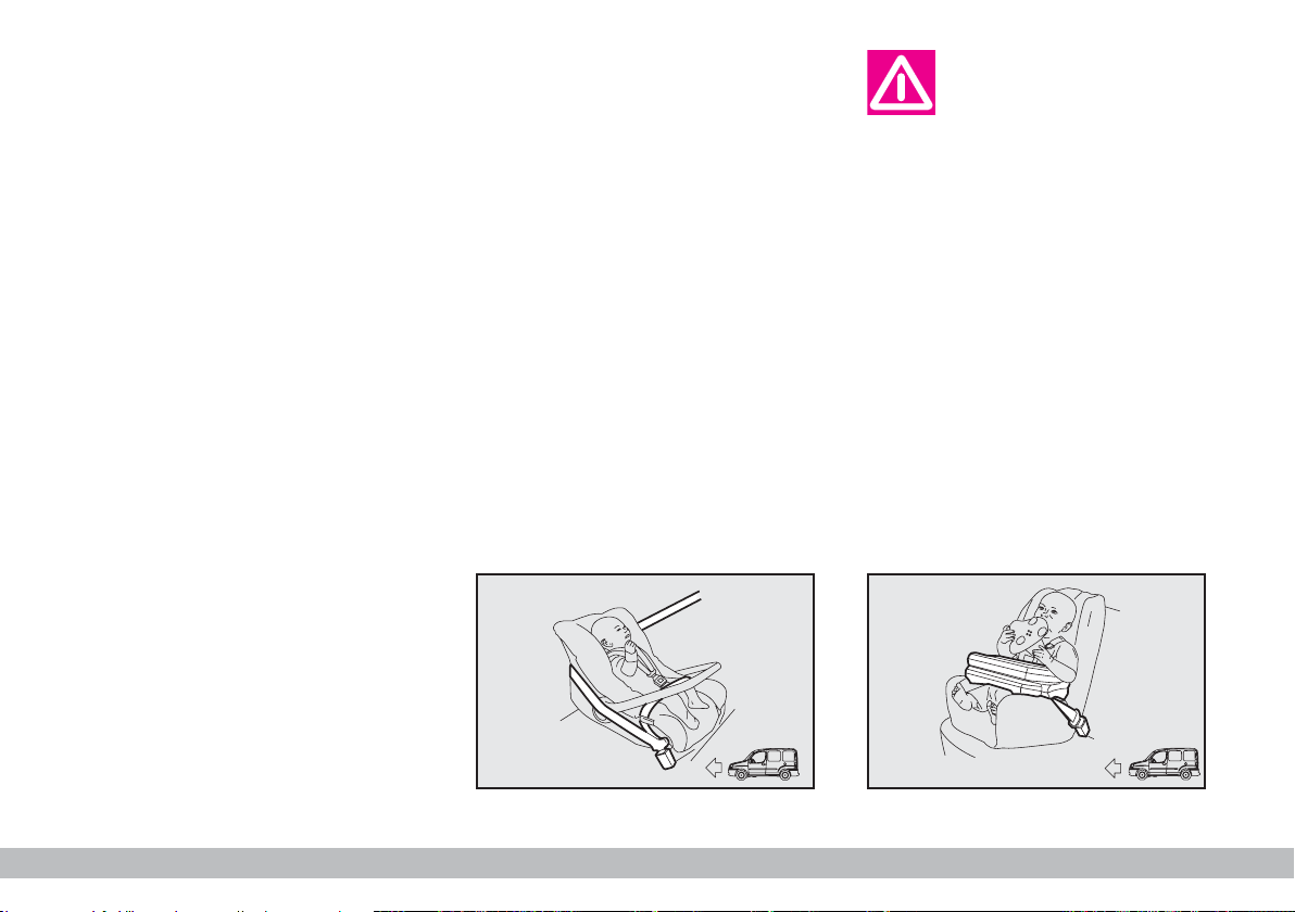
GROUP 0 and 0+
Babies up to 13 kg must be carried
facing backwards on a cradle seat,
which, supporting the head, does not
induce stress on the neck in the event
of sharp deceleration.
The cradle is restrained by the vehicle seat belts, as shown in fig. 14 and
in turn it must restrain the child with
its own belts.
fig. 14
The figure is only an example for mounting. Attain to the instructions
for fastening which must be enclosed with the specific child restraining system you are using.
GROUP 1
Children from 9 to 18 kg are to be
seated facing forward in child seats
with front cushion fig. 15. The vehicle seat belt secures both seat and
child.
F0A0440b
fig. 15
F0A0441b
16
GETTING TO KNOW YOUR VEHICLE
Page 18
The figure is only an example. Attain to the instructions for fastening
which must be enclosed with the
specific child restraint system you
are using.
Seats exist which are
suitable for covering
weight groups 0 and 1
with a rear connection to the vehicle belts and their own belts to
restrain the child. Due to their
size, they can be dangerous if installed incorrectly fastened to the
vehicle belts with a cushion.
Carefully follow the instructions
for installation provided with the
seat.
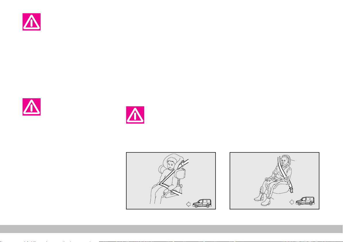
GROUP 2
Children from 15 to 25 kg can be secured directly with the vehicle seat
belts. The seat has the purpose of positioning the child correctly with respect to the seat belt so that the diagonal section crosses the child’s chest
(never the child’s throat) and the horizontal section fits snugly on the child’s
hips (and not the child’s abdomen) fig.
16.
The figure is only an example. Attain to the instructions for fastening
which must be enclosed with the
specific child restraint system you
are using.
GROUP 3
For children from 22 kg up to 36 kg
the size of the child’s chest no longer
requires a support to space the child’s
back from the seat back.
Fig. 17 shows proper child seat positioning on the rear seat.
Children taller than 1.50 m can wear
seat belts like adults.
F0A0442b
F0A0443b
fig. 16
fig. 17
GETTING TO KNOW YOUR VEHICLE
17
Page 19
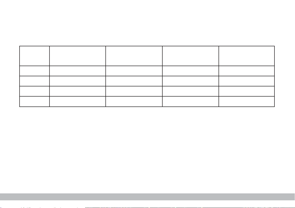
Passenger seat compliance with regulations on child’s seat use
Fiat Doblò complies with the new EC Directive 2000/3/CE regulating child’s seat assembling on the different vehicle seats
according to the table below:
Group
Group 0, 0+ up to 13 kg U U X
Group 1 9 - 18 kg U U X
Group 2 15 - 25 kg U U X
Group 3 22 - 36 kg U U X
Range of weight
FRONT SEAT
Front passenger
REAR SEAT
second row
Side and central passengers
REAR SEAT
third row
Side passengers
Key:
U = suitable for child restraint systems of the “Universal” category, according to European Standard ECE-R44 for the spec-
ified “Groups”.
X = Unsuitable for children in this group.
18
GETTING TO KNOW YOUR VEHICLE
Page 20

To sum up the safety
precautions to follow when
transporting children.
1) The recommended position for
installing child’s seat is on the rear seat,
as it is the most protected in the case
of a crash.
In vehicles fitted with
passenger airbag, never
place child’s restraint sys-
tems on the front seat.
2) If the passenger’s airbag is deac-
tivated always check the warning light
on the instrument panel to make
F
sure that it has actually been deactivated.
3) Attain to the instructions for fastening the specific child restraint system which you are using. These instructions must be provided by the
manufacturer. Keep the child restraint
system installation instructions with
the vehicle documents and with this
Handbook. Never use a child restraint
system without installation instructions.
4) Always check the seat belt is well
fastened by pulling the webbing.
5) Only one child is to be strapped
to each retaining system.
6) Always check the seat belts do
not fit around the child’s throat.
7) While travelling, do not let the
child sit incorrectly or release the
belts.
8) Passengers should never carry
children on their laps. No-one, however strong they are, can hold a child
in the event of a crash.
9) Replace the child restraint system
after an accident.
GETTING TO KNOW YOUR VEHICLE
19
Page 21
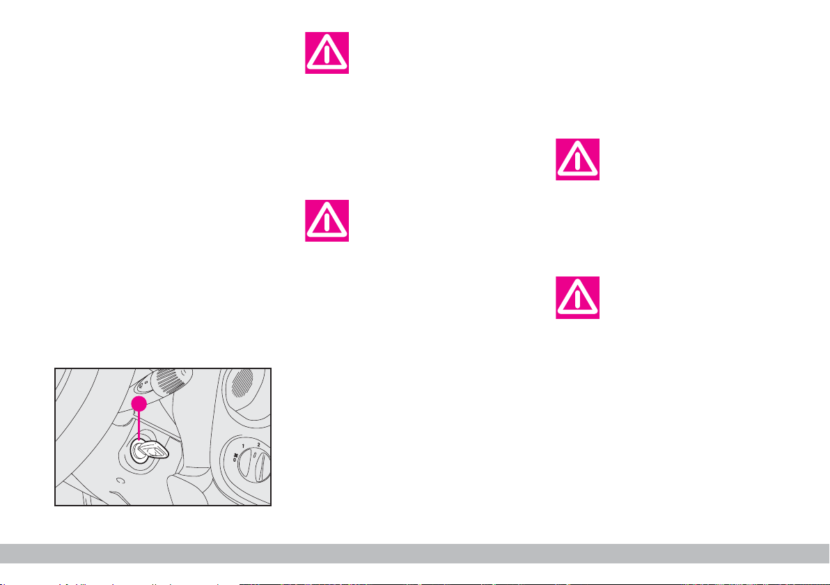
IGNITION DEVICE
A
The key can be turned to 4 different
positions fig. 26:
– STOP: engine off, key can be removed, steering column locked. Some
electrical devices can be worked (e.g.
sound system, electric window
winders).
– MAR: drive position. All electrical
devices can be used.
– AVV: engine ignition.
– PARK: engine off, parking lights
on, steering column locked. Press button A and turn the key to PARK.
If the ignition device is
tampered with (e.g.: attempted theft), have it
checked over by a Fiat Dealership
as soon as possible.
When you get out of the
vehicle, always remove
the ignition key. This will
prevent anyone from accidentally working the controls. Remember to apply the handbrake and,
if the vehicle is faced down on a
steep slope engage the first gear.
If it is facing up, engage the reverse gear. Never leave unsupervised children in the vehicle.
F0A0018b
STEERING COLUMN LOCK
To engage the lock: remove the
ignition key at STOP or PARK and
turn the steering wheel until it locks.
To release the lock: rock the
steering wheel slightly as you turn the
ignition key to MAR.
Never remove the ignition key while the vehicle
is moving. The steering
wheel would automatically lock
as soon as you try to turn it. This
also applies when the vehicle is
being towed.
It is absolutely forbidden
to carry out whatever after-market operation in-
volving steering system or steering column modifications (e.g.: installation of anti-theft device)
that could badly affect performance and safety, cause the lapse
of warranty and also result in
non-compliance of the vehicle
with homologation requirements.
fig. 26
20
GETTING TO KNOW YOUR VEHICLE
Page 22
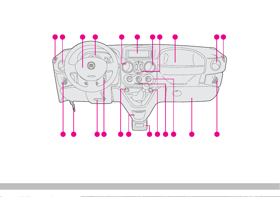
DASHBOARD
The presence and the position of the instruments and warning lights may vary according to the versions.
1 43 5 6 7 8 9 10 11
2
20212223
12131416 151719 18
F0A0701b
fig. 27
1. Fixed side vent - 2. Adjustable side vent - 3. Horn - 4. Instrument panel - 5. Adjustable central vent - 6. Glove compartment - 7. Adjustable central vent - 8. Central controls - 9. Glove compartment - 10. Adjustable side vent - 11. Fixed side
vent - 12. Front right-hand speaker housing -13. Glove compartment - 14. Heater/ventilation/climate control system controls - 15. Recirculation slider - 16. Additional power socket - 17. Glove compartment - 18. Ashtray - 19. Cigar lighter -
20. Ignition switch - 21. Steering wheel adjustment lever - 22. Bonnet opening lever - 23. Front left-hand speaker housing.
GETTING TO KNOW YOUR VEHICLE
21
Page 23
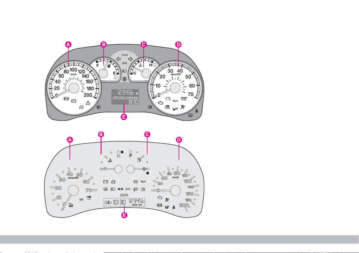
INSTRUMENT PANEL
1.4 8V - 1.3 Multijet -
1.9 Multijet versions
A - Speedometer (speed indicator)
B - Fuel level gauge with reserve
warning light
C - Engine coolant temperature gauge
and max. temperature warning light
D - Rev counter
E - Multifunction display
m
Warning lights
and care only
provided on Diesel versions.
fig. 28
fig. 29
22
GETTING TO KNOW YOUR VEHICLE
F0A0444b
F0A0445b
Natural Power versions
A - Rev counter.
B - Engine coolant temperature
gauge and excessive temperature
warning light.
C - Fuel level gauge with reserve
warning light.
D - Speedometer.
E - Digital display.
Warning lights
m
and care only
provided on Diesel versions.
Page 24
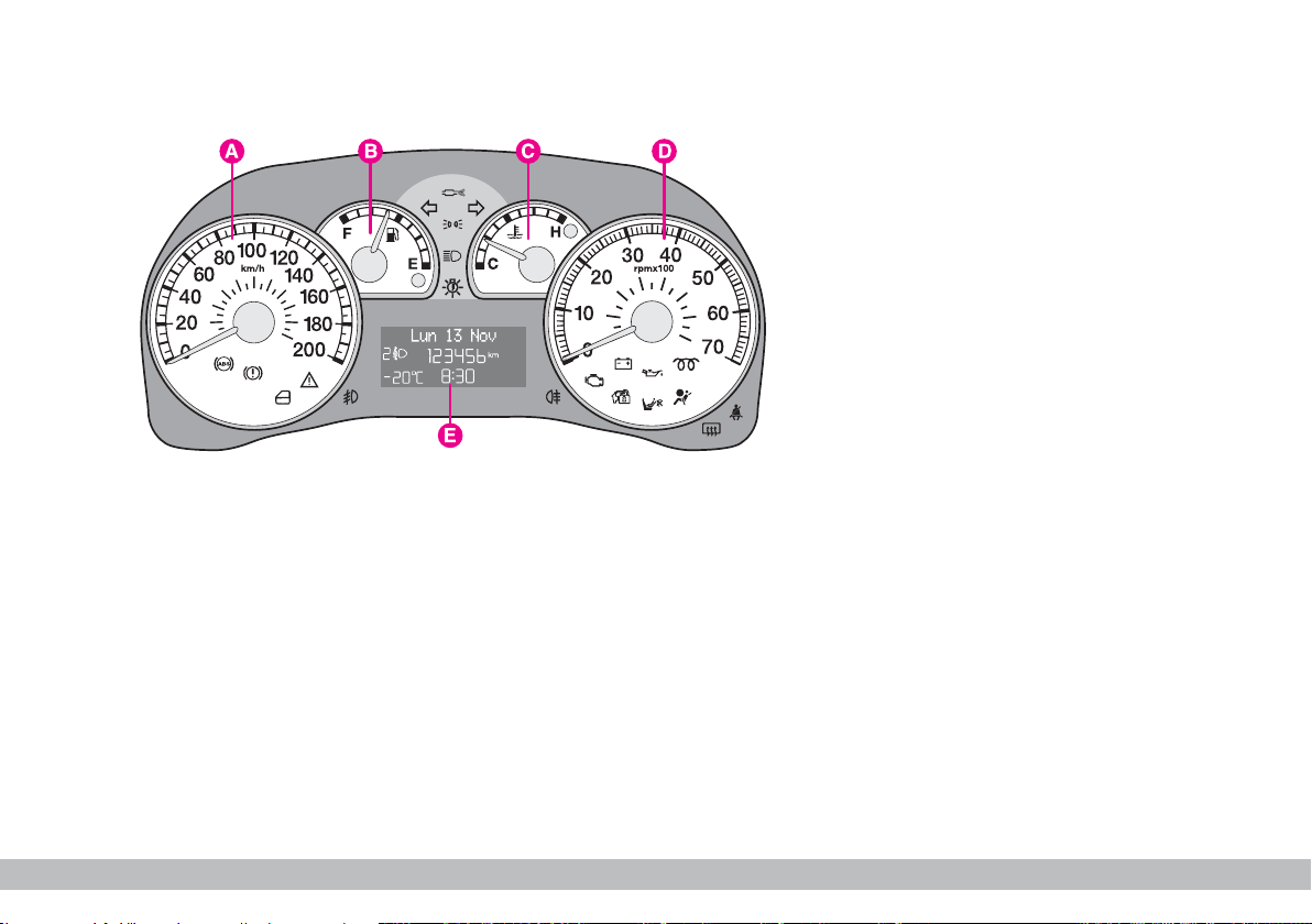
1.4 8V - 1.3 Multijet -
1.9 Multijet versions
A - Speedometer
B - Fuel level gauge with reserve
warning light.
C - Engine coolant temperature
gauge and excessive temperature
warning light.
D - Rev counter.
E - Digital display.
m
Warning lights
and care only
provided on Diesel versions.
fig. 30 - With outside temperature sensor and/or Diesel
Particulate Filter for Multijet versions.
F0A0500b
GETTING TO KNOW YOUR VEHICLE
23
Page 25
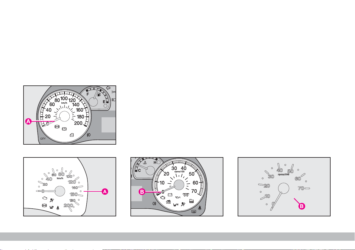
INSTRUMENTS
SPEEDOMETER
The speedometer A-fig. 31 - 32
shows the vehicle speed.
fig. 31
REV COUNTER
Rev. counter B-fig. 33 - 34 shows
engine rpm.
F0A0501b
IMPORTANT The electronic system progressively blocks fuel flow to
prevent engine from overrevving. This
will lead to a progressive loss of engine power. When the engine is idling,
the rev counter may indicate a gradual or sudden highering of the speed.
This is normal as it takes place during
normal operation, for example when
activating the climate control system
or the fan. In particular a slow change
in the speed preserves the battery
charge.
fig. 32
24
GETTING TO KNOW YOUR VEHICLE
F0A0446b
fig. 33
F0A0447b
F0A0227b
fig. 34
Page 26
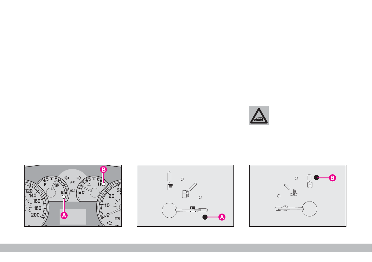
FUEL LEVEL GAUGE
The needle shows the fuel present in
the tank. When the fuel reserve warning light A-fig. 35 - 36 comes on (on
certain versions with the dedicated
message on the reconfigurable multifunction display) it means that there
are approximately 5-7 litres of fuel left
in the tank.
E - tank empty.
F - tank full.
Never travel with the tank almost
empty: lack of fuel could damage the
catalyser.
IMPORTANT The needle will
point to E and the reserve warning
light A will flash to indicate a fault in
the system. Contact a Fiat Dealer-
ship to have the system checked.
ENGINE COOLANT
TEMPERATURE GAUGE
This gauge shows the temperature of
the engine coolant fluid and begins
working when the fluid temperature
exceeds approx. 50 °C.
Under normal conditions, the needle
should move to different positions of
the scale according to the working
conditions and engine cooling conditions.
C - Low engine coolant temperature
H - High engine coolant temperature
Warning light B-fig. 35 - 37 comes
on (on certain versions with the dedicated message on the reconfigurable
multifunction display) to indicate that
engine coolant temperature is too
high; in this event stop the engine and
contact Fiat Dealership.
If the needle reaches the
red area, stop the engine
immediately and contact
a Fiat Dealership.
fig. 35
F0A0343b
fig. 36
F0A0225b
fig. 37
GETTING TO KNOW YOUR VEHICLE
F0A0226b
25
Page 27
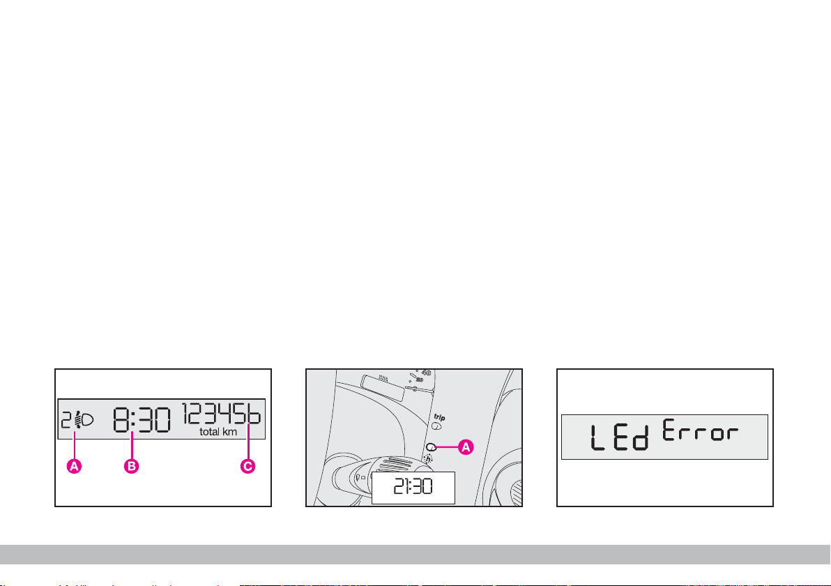
DIGITAL DISPLAY
“STANDARD” SCREEN fig. 38
The standard screen shows the fol-
lowing indications:
A - Headlight aiming position display
(with dipped beam headlights on).
B - Clock (always displayed, also with
key removed and front doors closed).
C - Odometer (km or miles cov-
ered).
CONTROL BUTTONS fig. 39
A - Clock.
CLOCK fig. 39
To adjust the clock press button A.
The clock will advance by one unit
each time the button is pressed. Press
the button and hold it down for a few
seconds to rapidly advance the time
automatically. When the clock draws
near to the correct time, release the
button and complete the regulation
manually.
WARNING LIGHT TEST
fig. 40
The following warning lights are test-
ed:
– handbrake on/low brake fluid lev-
el;
– ABS and EBD system (where pro-
vided);
This tests are carried out automatically when turning the ignition key to
MAR and during normal operation
when a fault is found. At the end of the
initial check, the display will show failures, if any (through one or more
warning lights) by the wording “LEd
Error” flashing for about 10 seconds.
fig. 38
26
GETTING TO KNOW YOUR VEHICLE
F0A0502b
fig. 39
F0A0229b
F0A0503b
fig. 40
Page 28
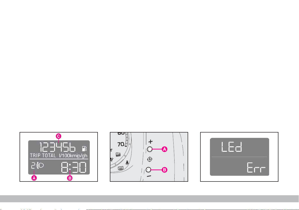
MULTIFUNCTION
DISPLAY
STANDARD SCREEN fig. 41
The standard screen shows the fol-
lowing indications:
A - Headlight aiming position display
(with dipped beam headlights on).
B - Clock.
C - Odometer (km or miles cov-
ered).
Note With ignition key removed,
when opening one of the front doors
the display comes on showing the
clock and km/mi covered for a few
seconds.
CLOCK fig. 42
To adjust the clock press button A
to increase minutes and button B to
decrease minutes. The clock will advance by one unit each time the button is pressed. Press the button and
hold it down for a few seconds to
rapidly advance the time automatically. When the clock draws near to the
correct time, release the button and
complete the regulation manually.
WARNING LIGHT TEST
fig. 43
The following warning lights are test-
ed:
– handbrake on/low brake fluid lev-
el;
– ABS and EBD system (where pro-
vided);
This tests are carried out automatically when turning the ignition key to
MAR and during normal operation
when a fault is found. At the end of the
initial check, the display will show failures, if any (through one or more
warning lights) by the wording LEd Err
flashing for about 10 seconds.
fig. 41
F0A0331b
fig. 42
F0A0340b
fig. 43
GETTING TO KNOW YOUR VEHICLE
F0A0333b
27
Page 29
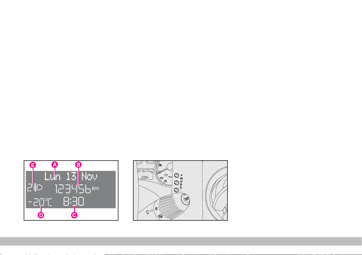
RECONFIGURABLE MULTIFUNCTION
DISPLAY (where provided)
The vehicle can be provided with the
reconfigurable multifunction display
that shows useful information, according to the previous settings made,
necessary when driving.
“STANDARD” SCREEN fig. 44
The standard screen shows the following indications:
A - Date
B - Odometer (km or miles covered)
C - Clock
D - External temperature (where
provided)
E - Headlight aiming position (only
with dipped beam headlights on).
Note With key removed, when
opening one of the front doors, the
display will turn on and show for a few
seconds the clock and the km or mi
covered.
CONTROL BUTTONS fig. 45
+ To scroll the displayed menu and
the related options upwards or to increase the value displayed .
F0A0504b
MODE Brief press to open the
menu and/or to move to
next screen or to confirm
the the option required.
Long press to go back to
the standard screen.
– To scroll the displayed menu and
the related options downwards or to
decrease the value displayed.
Note Buttons + and – activate different functions according to the following situations:
To adjust light inside the
passenger compartment
– when standard screen is active, to
adjust brightness inside the passenger
compartment.
Setup menu
– to scroll the menu options up-
F0A0512b
wards and downwards;
– to increase or decrease values during settings.
fig. 44
28
fig. 45
GETTING TO KNOW YOUR VEHICLE
Page 30

SETUP MENU
The menu comprises a series of functions arranged in a “circular fashion”
which can be selected through buttons
+ and – to access the different select
operations and settings (setup) given
in the following paragraphs.
The setup menu can be activated by
pressing briefly button MODE.
Single presses on buttons + or – will
scroll the setup menu options.
Handling modes differ with each other according to the characteristic of
the option selected.
Selecting a menu option
– press briefly button MODE to select the menu option to set;
– press buttons + or – (by single
presses) to select the new setting;
– press briefly button MODE to
store the new setting and to go back
to the previously selected menu option.
Selecting “Set Date”
and “Set time”:
– briefly press button MODE to select the first value to change (e.g.
hours /minutes or year / month / day);
– press buttons + or – (by single
presses) to select the new setting;
– briefly press button MODE to
store the new setting and to go to the
next setup menu option, if this is the
last one you will go back to the previously selected option of the main
menu.
Press button MODE for long:
– to quit the setup menu and to save
only the settings stored yet by the user
(and confirmed by pressing briefly button MODE).
The setup menu displaying is timed;
when quitting the menu due to timing expiry, only settings stored yet by
the user (and confirmed by pressing
briefly button MODE) will be saved.
GETTING TO KNOW YOUR VEHICLE
29
Page 31

Example:
Italiano
Türkçe
Nederland
Polski
MODE
briefly
press
button
+
Deutsch
Português
+
–
BUTTON VOL.
English
Español
Français
–
SERVICE
Briefly press button MODE to start surfing from the
standard screen. To surf the menu use buttons + or –.
Note For safety reasons, when the vehicle is running,
it is possible to access only the reduced menu (for setting the “Speed Beep”). When the vehicle is stationary
access to the whole menu is enabled. On vehicles
equipped with Connect Nav+ many functions are displayed on the navigator display.
+
–
EXIT MENU
SPEED
BEEP
+
Example:
Day
Year
+
–
TRIP B
–
SET TIME
CLOCK MODE
+
–
Month
MODE
briefly
press button
+
–
SET DATE
–
AUTOCLOSE
+
30
+
–
BUZZER VOL.
–
LANG.
+
GETTING TO KNOW YOUR VEHICLE
DIST. UNIT
–
TEMP. UNIT
–
CONS.
–
+
++
–
+
F0A0505g
Page 32

Speed limit (Speed Beep)
With this function it is possible to set
the vehicle speed limit (km/h or mph),
when this limit is exceeded the driver
is immediately alerted (see section
“Warning lights and messages”).
To set the speed limit, proceed as
follows:
– briefly press button MODE: (Off)
will flash on the display;
– press button +: (On) will flash on
the display;
– briefly press button MODE and
then + or – to set the required speed
(during setting the value flashes).
Note The possible setting is between 30 and 250 km/h, or between
20 and 155 mph depending on the unit
set previously (see “Distance unit
(Dist. Unit)” paragraph described later. Every press on button + / – in-
creases/decreases by 5 units. Keeping
the button + / – pressed obtains the
automatic fast increase or decrease.
When you are near the required setting complete adjustment by single
presses.
– briefly press button MODE to go
back to the menu screen or press the
button for long to go back to the standard screen without storing settings.
To cancel the setting, proceed as follows:
– briefly press button MODE: (On)
will flash on the display;
– press button –: (Off) will flash on
the display;
– briefly press button MODE to go
back to the menu screen or press the
button for long to go back to the standard screen without storing settings.
Trip B On/Off (Trip B)
Through this option it is possible to
activate (On) or deactivate (Off) the
Trip B (partial trip).
For further details see paragraph
“Trip computer”.
For activation / deactivation, proceed
as follows:
– briefly press button MODE: (On)
or (Off) will flash on the display (according to previous setting);
– press button + or – for setting;
– briefly press button MODE to go
back to the menu screen or press the
button for long to go back to the standard screen without storing settings.
Set clock (Set clock)
This function enables to set the
clock.
To set the clock (hours - minutes)
proceed as follows:
– briefly press button MODE:
“hours” will flash on the display;
GETTING TO KNOW YOUR VEHICLE
31
Page 33

– press button + or – for setting;
– briefly press button MODE: “min-
utes” will flash on the display;
– press button + or – for setting.
Note Every press on the button +
or – increases/decreases by one unit.
Keeping the button pressed obtains
automatic fast increase/decrease.
When you are near the required setting complete adjustment by single
presses.
– briefly press button MODE to go
back to the menu screen or press the
button for long to go back to the standard screen without storing settings.
Clock mode (Clck. Mode)
This function is used to set the clock
in the 12h (12 hours) or 24h (24
hours) mode.
For setting proceed as follows:
– briefly press button MODE 12h or
24h will flash on the display (according to previous setting);
– press button + or – for setting;
– briefly press button MODE to go
back to the menu screen or press the
button for long to go back to the standard screen without storing settings.
Set date (Adjust Date)
This function enables to update the
date (year - month - day).
To correct the date proceed as follows:
– briefly press button MODE:
“year” will flash on the display;
– press button + or – for setting;
– briefly press button MODE:
“month” will flash on the display;
– press button + or – for setting;
– briefly press button MODE: “day”
will flash on the display;
– press button + or – for setting.
Note Every press on the button +
or – increases/decreases by one unit.
Keeping the button pressed obtains
automatic fast increase/decrease.
When you are near the required setting complete adjustment by single
presses.
– briefly press button MODE to go
back to the menu screen or press the
button for long to go back to the standard screen without storing settings.
32
GETTING TO KNOW YOUR VEHICLE
Page 34

Automatic door locking with
vehicle running (Autoclose)
(where provided)
When activated (On), this function
locks automatically the doors when
the vehicle speed exceeds 20 km/h.
To activate (On) or to deactivate
(Off) this function proceed as follows:
– briefly press button MODE: On or
Off will flash on the display (according
to previous setting);
– press button + or – for setting;
– briefly press button MODE to go
back to the menu screen or press the
button for long to go back to the standard screen without storing settings.
“Distance” unit (Dist. Unit)
With this function it is possible to set
the unit in km or mi.
To set the required unit proceed as
follows:
– briefly press button MODE: km or
mi will flash on the display (according
to previous setting);
– press button + or – for setting;
– briefly press button MODE to go
back to the menu screen or press the
button for long to go back to the standard screen without storing settings.
“Consumption” unit (Cons.)
If the distance unit set is km (see previous paragraph) the display will enable
to set the fuel consumption unit (km/l
or l/100km).
If the distance unit set is mi (see previous paragraph) fuel consumption will
be displayed in mpg.
To set the required unit proceed as
follows:
– briefly press button MODE: km/l
or l/100km will flash on the display (according to previous setting);
– press button + or – for setting;
– briefly press button MODE to go
back to the menu screen or press the
button for long to go back to the standard screen without storing settings.
GETTING TO KNOW YOUR VEHICLE
33
Page 35

“Temperature” unit (Temp.
Unit) (where provided)
This function enables to set the tem-
perature unit (°C or °F).
To set the required unit proceed as
follows:
– briefly press button MODE: °C or
°F will flash on the display (according
to previous setting);
– press button + or – for setting;
– briefly press button MODE to go
back to the menu screen or press the
button for long to go back to the standard screen without storing settings.
Selecting the language (Lang.)
Display messages can be shown in
different languages: Italian, German,
English, Spanish, French, Portuguese,
Polish and Dutch.
To set the required language proceed as follows:
– briefly press button MODE: the
previously set “language” will flash on
the display;
– press button + or – for setting;
– briefly press button MODE to go
back to the menu screen or press the
button for long to go back to the standard screen without storing settings.
Adjusting the failure/warning
buzzer volume (Buzzer Vol.)
With this function the volume of the
buzzer accompanying any failure/warning indication can be adjusted according to 8 levels.
To adjust the volume proceed as follows:
– briefly press button MODE: the
previously set volume “level” will flash
on the display;
– press button + or – for setting;
– briefly press button MODE to go
back to the menu screen or press the
button for long to go back to the standard screen without storing settings.
Adjusting the button volume
(Button Vol.)
With this function the volume of the
roger-beep accompanying the activation of buttons MODE, + and – can
be adjusted according to 8 levels.
To adjust the volume proceed as follows:
– briefly press button MODE: the
previously set volume “level” will flash
on the display;
– press button + or – for setting;
– briefly press button MODE to go
back to the menu screen or press the
button for long to go back to the standard screen without storing settings.
34
GETTING TO KNOW YOUR VEHICLE
Page 36

Scheduled Servicing (Service)
Through this function it is possible to
display information connected to
proper vehicle servicing.
Proceed as follows:
– briefly press button MODE: service in km or mi, according to previous setting, will be displayed (see paragraph “Distance unit”);
– press button + or – to select displaying in days;
– briefly press button MODE to go
back to the menu screen or press the
button for long to go back to the standard screen.
Note The “Service schedule” includes vehicle maintenance every
20,000 km (or 12,000 mi) or every
year; this is shown automatically, with
the ignition key at MAR, starting from
2,000 km (or 1,240 mi) or 30 days
from this deadline and it is shown again
every 200 km (or 124 mi) or 3 days.
Below 200 km servicing indications are
displayed more frequently. As concerns 1.3 Multijet versions, change air
cleaner, engine oil and engine oil filter at the intervals specified in the Ser-
vice schedule, see section “Vehicle
maintenance”. Service indications will
be displayed km or mi according to
previous unit setting. When a programmed maintenance interval
(coupon) is near to come, turning the
ignition key to MAR, the display will
show the message “Service” followed
by the number of km/mi to go before
vehicle servicing. “Scheduled servicing”
message is displayed in km/mi or days
according to the approaching service
interval. Contact Fiat Dealership to
carry out any service operation provided by the “Service schedule” or
“Annual inspection schedule”, and to
reset the display.
Exit Menu
This is the last function that closes
the circular setting cycle listed in the
initial menu screen.
Briefly press button MODE to go
back to the standard screen.
Press button – to return to the first
menu option (Speed Beep).
GETTING TO KNOW YOUR VEHICLE
35
Page 37

TRIP COMPUTER
General features
The “Trip computer” displays information (with ignition key at MAR, relating to the operating status of the vehicle. This function comprises the
“General trip” concerning the complete mission of the vehicle and “Trip
B” (on reconfigurable multifunction
display only) concerning the partial vehicle mission. This function (as shown
in fig. 48) is contained within the complete mission.
Both functions are resettable (reset
- start of new mission).
“General Trip” displays the figures
relating to:
– Range
– Trip distance
– Average consumption
– Instant consumption (present on
multifunction display and reconfigurable multifunction display)
– Average speed
– Travel time (driving time).
“Trip B”, available on reconfigurable
multifunction display only, shall be
used to display the figures relating to:
– Trip distance B
– Average consumption B
– Average speed B
– Travel time B (driving time).
Note The “Trip B” function can be
excluded (see paragraph “Trip B
On/Off”). “Range to empty” cannot be
reset.
VALUES DISPLAYED
Range (*)
This value shows the distance in km
(or mi) that the vehicle can still cover
before needing fuel, assuming that driving conditions are kept unvaried. The
display will show “——” in the following cases:
– value lower than 50 km (or 30 mi)
– vehicle left parked with engine running for long.
(*) On Natural Power versions, for petrol con-
sumption only.
Trip distance
This value shows the distance covered from the start of the new mission.
36
GETTING TO KNOW YOUR VEHICLE
Page 38

Average consumption (*)
This value shows the average consumption from the start of the new
mission.
(*) On Natural Power versions, for petrol con-
sumption only.
Instant consumption
This value shows instant fuel consumption (this value is updated second
by second). If parking the vehicle with
engine on, the display will show “----”.
Average speed
This value shows the vehicle average
speed as a function of the overall time
elapsed since the start of the new mission.
Travel time
This value shows the time elapsed
since the start of the new mission.
IMPORTANT Lacking information,
Trip computer values are displayed
with “----” When normal operating
condition is reset, calculation of different units will restart regularly. Values displayed before the failure will
not be reset.
TRIP button fig. 46 and fig. 47
(Natural Power versions)
Button TRIP shall be used (with ignition key at MAR), to display and to
reset the previously described values
to start a new mission:
– short push to display the different
values
– long push to reset and then start
a new mission.
New mission
Reset can be:
– “manual” resetting by the user, by
pressing the relevant button;
– “automatic” resetting, when the
“Trip distance” reaches 3999.9 km or
9999.9 km (according to the type of
display) or when the “Travel time”
reaches 99.59 (99 hours and 59 minutes);
– after disconnecting/reconnecting
the battery.
IMPORTANT The reset operation
in the presence of the screens concerning the “General Trip” will also reset the “Trip B”. The reset operation
in the presence of the screens concerning the “Trip B” makes it possible to reset only the information associated with this function.
GETTING TO KNOW YOUR VEHICLE
37
Page 39

F0A0332b
Start of journey procedure
F0A0228b
With ignition key at MAR, press and
keep button TRIP pressed for over 2
seconds to reset.
fig. 46
fig. 48
38
Reset GENERAL TRIP
End of complete mission
Start of new mission
˙
TRIP B
˙
Reset TRIP B
End of partial mission
Start of new partial mission
GETTING TO KNOW YOUR VEHICLE
fig. 47
GENERAL TRIP
Reset TRIP B
˙
˙
End of partial mission
Start of new
partial mission
TRIP B
Reset TRIP B
˙
˙
End of partial mission
Start of new
partial mission
Reset GENERAL TRIP
End of complete mission
Start of new mission
˙
TRIP B
˙
Reset TRIP B
End of partial mission
Start of new
partial mission
Page 40

WARNING LIGHTS
AND MESSAGES
GENERAL INFORMATION
Turning on of warning light is accompanied by specific message and/or
by buzzer sound where provided by
instrument panel. These indications
are concise and cautionary and
shall not be considered as exhaustive
and/or as an alternative to the specifications contained in this Owner
Handbook which shall always be read
through carefully and thoroughly. In
case of failure indication always re-
fer to the specifications contained
in this section.
IMPORTANT Failure indications
displayed are divided into two categories: very serious and less seri-
ous failures.
Very serious failures are indicated
by a warning “cycle” repeated until failure is eliminated.
Less serious failures are indicated
by a limited warning “cycle”.
The warning cycle of both failure categories can be stopped by pressing
button MODE. The instrument panel warning light will stay on until eliminating the fault.
LOW BRAKE
x
(red)
Turning the ignition key to MAR the
warning light turns on, but it should go
off after few seconds.
Low brake fluid level
The warning light turns on when the
level of the brake fluid in the reservoir
falls below the minimum level, due to
possible leak in the circuit.
FLUID LEVEL (red)
HANDBRAKE ON
On certain versions the dedicated
message is displayed.
If the warning light
turns on when travelling
(on certain versions to-
gether with the message on the
display) stop the vehicle immediately and contact Fiat Dealership.
Handbrake on
The warning light turns on when the
handbrake is on.
On certain versions, if the vehicle is
moving the buzzer will also sound.
IMPORTANT If the warning light
turns on when travelling, check that
the handbrake is not engaged.
x
GETTING TO KNOW YOUR VEHICLE
39
Page 41

AIR BAG FAILURE
¬
The warning light stays on glowing
steadily if there is a failure in the air
bag system.
On certain versions the dedicated
message is displayed.
turn on or stays on when travelling there could be a failure in
safety systems; in this event air
bags or pretensioners could not
trigger in case of impact or, in a
minor number of cases, they
could trigger accidentally. Contact Fiat Dealership immediately to have the system checked.
(red) (where provided)
Turning the ignition key to
MAR the warning light turns
on, but it should go off after
few seconds.
If when turning the ignition key to MAR, the
warning light
¬
does not
The failure of the warning light ¬(warning light
off) is also indicated by
the flashing for more than the
normal 4 seconds of the passenger’s front air bag deactivated
warning light F.
HIGH TEMPERATURE
ENGINE COOLANT
ç
FLUID (red)
Turning the ignition key to MAR the
warning light turns on, but it should go
off after few seconds.
The warning light turns on when the
engine is overheated.
If the warning light comes on, proceed as follows:
– normal driving conditions: stop
the vehicle, switch off the engine and
check whether the water level in the
reservoir is not below the MIN mark.
Otherwise wait for few seconds to allow the engine cooling, then open
slowly and carefully the cap, top up
coolant and check whether its level is
falling between MIN and MAX marks
in the reservoir. Check visually any
leak. If, when restarting, the warning
light comes on again, contact Fiat
Dealership.
– vehicle heavy duty (e.g.: towing
trailer uphill of fully laden vehicle): decrease speed, if the warning light stays
on, stop the vehicle. Wait for 2 or 3
minutes leaving the engine on and
slightly accelerated to further activate
the circulation of the coolant fluid,
then switch the engine off. Check
proper coolant level as described previously.
40
GETTING TO KNOW YOUR VEHICLE
Page 42

IMPORTANT Under severe use of
the vehicle, keep the engine on and
slightly accelerated for few minutes
before switching it off. On certain versions the dedicated message is displayed.
LOW BATTERY
w
to MAR the warning light turns on,
but it should go out as soon as the engine is started (with the engine running
at idle speed a brief delay in going out
is allowed).
If the warning light stays on, contact
immediately Fiat Dealership.
x
The turning on at the same time of
warning lights
gine running indicates an EBD system
failure or that the system is unavailable; in this case heavy braking may
cause the rear wheels to lock before
time, with the possibility of skidding.
CHARGE (red)
Turning the ignition key
EBD
>
FAILURE
(red) (amber)
x
and >with the en-
Drive with the utmost care to the
nearest Fiat Dealership to have the
system checked.
On certain versions the dedicated
message is displayed.
LOW ENGINE
v
EXHAUST OIL
(Multijet versions) (red)
Low engine oil pressure
Turning the ignition key to MAR the
warning light turns on, but it should go
out as soon as the engine is started.
On certain versions the dedicated
message is displayed.
versions together with the message on the display) stop the engine immediately and contact a
Fiat Dealership.
OIL PRESSURE
(red)
If the warning light
turns on when the vehicle
is travelling (on certain
v
Exhaust oil (Multijet versions)
The warning light with turn on flashing together with the message on the
display when the system detects that
the engine oil is exhaust.
After the initial signalling, each time
the engine is started, the
ing light will continue to flash cyclically for 3 minutes with intervals of 5 seconds with the warning light OFF until
the oil is changed.
If warning light
flashing, go to a Fiat Dealership immediately to
have the engine oil
changed and the warning light in
the instrument panel will go out.
Failure to do so may adversely affect the validity of the warranty.
SEAT BELTS NOT
<
al turns on glowing steadily with vehicle stationary and driver’s or passenger’s seat belt not fastened correctly. The warning light will turn on
flashing when, with vehicle moving, driver’s or passenger’s seat belt are not
fastened correctly.
FASTENED (red)
The warning light on the di-
v
v
warn-
is
GETTING TO KNOW YOUR VEHICLE
41
Page 43

INCOMPLETE
´
On certain versions the warning
light turns on when one or more
doors or the tailgate are not properly shut.
On certain versions the dedicated
message is displayed; symbols
indicate respectively left / right door
open.
A buzzer will sound when doors/tailgate are open and the vehicle is moving (only for versions with reconfigurable multifunction display).
DOOR LOCKING
(red)
¯/ ˙
INJECTION SYSTEM
U
EOBD SYSTEM FAILURE
(petrol versions - amber)
Injection system failure
Turning the ignition key to MAR the
warning light turns on but it should go
off after engine starting.
If the warning light stays on or turns
on when travelling, means a fault in the
supply/ignition system which could
cause high emissions at the exhaust,
possible lack of performance, poor
handling and high consumption levels.
On certain versions the dedicated
message is displayed.
In these conditions it is possible to
continue driving without however requiring heavy effort or high speed from
the engine. In any case, contact Fiat
Dealership as soon as possible.
FAILURE
(Multijet versions amber)
EOBD engine control system
failure
Under normal conditions, turning the
ignition key to MAR, the warning light
turns on, but it should go out as soon
as the engine is started. The initial
turning on indicates that the warning
light is working properly. If the warning light stays on or turns on when
travelling:
– glowing steadily: means a fault in
the supply/ignition system which could
cause high emissions at the exhaust,
possible lack of performance, poor
handling and high consumption levels.
On certain versions the dedicated
message is displayed.
In these conditions it is possible to
continue driving without however requiring heavy effort or high speed from
the engine. Prolonged use of the vehicle with the warning light on may
cause damages. Contact Fiat Deal-
ership as soon as possible. The warning light goes off if the fault disappears,
but it is still stored by the system.
– flashing: indicates the possibility
of damage to the catalyst (see “EOBD
system” in this section).
42
GETTING TO KNOW YOUR VEHICLE
Page 44

If the light flashes, it is necessary to
release the accelerator pedal to lower the speed of the engine until the
warning light stops flashing; continue
the journey at moderate speed, trying
to avoid driving conditions that may
cause further flashing and contact Fi-
at Dealership as soon as possible.
If, turning the ignition
key to MAR, the warning
light U does not turn on
or if it turns on glowing steadily
or flashing when travelling (on
certain versions together with
the message on the display), contact Fiat Dealership as soon as
possible. Warning light U oper-
ation can be checked by traffic
agents by proper equipment.
Comply with laws and regulations of the country where you
are driving.
FUEL RESERVE
ç
MAR the warning light turns on, but
it should go off after few seconds.
The warning light turns on when
about 5-7 litres fuel are left in the tank.
IMPORTANT The warning light
flashes to indicate a failure, contact
Fiat Dealership as soon as possible
to have the system checked.
On certain versions the dedicated
message is displayed.
(amber)
Turning the ignition key to
INEFFICIENT ABS
>
to MAR the warning light turns on,
but it should go off after few seconds.
The warning light turns on when the
system is inefficient or unavailable. In
this case the braking system keeps its
effectiveness unchanged, but without
the potential offered by the ABS system. Caution is advisable and it is necessary to contact Fiat Dealership.
On certain versions the dedicated
message is displayed.
SYSTEM (amber)
Turning the ignition key
GETTING TO KNOW YOUR VEHICLE
43
Page 45

FRONT
F
Warning light
front passenger’s air bag is deactivated.
With front passenger’s air bag on,
turning the ignition key to MAR,
warning light
for about 4 seconds, it flashes for other 4 seconds and then it shall go off.
by intermittent flashing, over 4
seconds, of warning light F. In
this event warning light ¬ indicates that there could be a failure
in safety systems. Contact Fiat
Dealership immediately to have
the system checked.
PASSENGER’S AIR
BAG DEACTIVATED
(amber)
F
comes on when
F
comes on steadily
Warning light
cates also warning light ¬
failures. This is indicated
F
indi-
GLOW PLUG
m
GLOW PLUG WARMING FAILURE (Multijet versions - amber)
Spark plug pre-heating
Turning the ignition key to MAR, the
warning light turns on and it will turn
off when glow plugs reach the preset
temperature. Start the engine immediately after warning light switching off.
IMPORTANT With hot ambient
temperature, warning light stays on for
very short time.
Glow plug warming failure
The warning light turns on when
there is a failure in the glow plug
warming system. Contact Fiat Deal-
ership as soon as possible.
On certain versions the dedicated
message is displayed.
WARMING
(Multijet versions - amber)
WATER IN DIESEL
c
Turning the ignition key to MAR the
warning light turns on, but it should go
off after few seconds. The warning
light
in the diesel fuel filter. On certain versions the warning light èturns on
and the display shows a dedicated
message.
FUEL FILTER
(Multijet versions amber)
c
turns on when there is water
44
GETTING TO KNOW YOUR VEHICLE
Page 46

The presence of water in
the fuel circuit may cause
serious damage to the en-
tire injection system and cause irregular engine operation. If the
warning light cor èturns on
(on certain versions together
with the message on the display)
contact Fiat Dealership as soon
as possible to have the system relieved. If the above indications
come on immediately after refuelling, water has probably been
poured into the tank: turn the engine off immediately and contact
Fiat Dealership.
VEHICLE
¢ Y
Turning the key to MAR the warning light shall flash only once and then
go off.
If with the ignition key at MAR, the
warning light stays on, this indicates a
possible failure (see “Fiat Code system” in section “Dashboard and controls”).
IMPORTANT The turning on at
the same time of the warning lights
and Yindicates a failure of the Fiat
CODE system.
If with the engine running the warning light
the vehicle is not protected by the engine inhibitor device (see “Fiat Code
system” in section “Dashboard and
controls”).
Contact Fiat Dealership to have all
the key memorised.
U
PROTECTION
SYSTEM
FAILURE FIAT CODE
(amber)
U
flashes, this means that
HEATED REAR
(
on when switching the heated rear
window on.
W
lights is failing:
– sidelights
– brake lights (third brake light ex-
cluded)
– rear fog guards
– direction indicators
– number plate lights.
WINDOW (amber)
The warning light turns
EXTERNAL LIGHT
FAILURE (amber)
The warning light turns on
when one of the following
GETTING TO KNOW YOUR VEHICLE
45
Page 47

The failure referring to these lights
could be: one or more blown bulbs,
a blown protection fuse or an electric
connection cut-off.
On certain versions the dedicated
message is displayed; symbols
indicate respectively the left / right
side.
REAR FOG LIGHTS
4
turned on.
(amber)
The warning light turns on
when the rear fog lights are
¯/ ˙
DIESEL
h
1.9 Multijet 120 HP versions)
(Amber)
The warning light turns on when the
diesel particulate filter is clogged and
the driving conditions do not enable
to activate automatically the reclaiming procedure.
To enable the cleaning procedure,
keep the vehicle running until the
warning light turns off.
The display will show the dedicated
message.
display to indicate that the cleaning procedure cannot be performed, contact Fiat Dealership
as soon as possible.
PARTICULATE
FILTER CLOGGED
(1.3 Multijet 85 HP and
Warning light Uturns
on together with the dedicated message on the
GENERIC
è
The warning light turns on in the fol-
lowing circumstances.
Engine oil pressure sensor
failure
The warning light comes on when
the engine oil pressure sensor is faulty.
Contact Fiat Dealership as soon as
possible.
On certain versions the dedicated
message is displayed.
Speed limit exceeded
The display will show the dedicated
message when the vehicle exceeds the
set speed limit (see “Reconfigurable
Multifunction Display” in this section).
On certain versions the dedicated
message is displayed.
FAILURE
INDICATION
(amber)
46
GETTING TO KNOW YOUR VEHICLE
Page 48

Diesel fuel filter sensor failure
The warning light comes on when
the diesel fuel filter sensor is faulty.
Contact Fiat Dealership as soon as
possible.
On certain versions the dedicated
message is displayed.
Water in diesel fuel filter
See what described for warning light
c
.
SIDELIGHTS
3
FOLLOW ME HOME (green)
Side/taillights and low beams
The warning light turns on when
side/taillights or low beams are turned
on.
AND LOW BEAMS
(green)
Follow me home
The warning light will turn when this
device is active (see “Follow me
home” in section “Dashboard and
controls”).
The display will show the dedicated
message.
FRONT FOG
5
on when the front fog lights are turned
on.
F
The warning light turns on when the
direction indicator control lever is
moved downwards or, together with
the right indicator, when the hazard
warning light button is pressed.
LIGHTS (green)
The warning light turns
LEFT-HAND
DIRECTION
INDICATOR (green -
intermittent)
RIGHT-HAND
D
The warning light turns on when the
direction indicator control lever is
moved upwards or, together with the
left indicator, when the hazard warning light button is pressed.
y
The warning light turns on when the
direction indicator control lever is
moved downwards or, together with
the right indicator, when the hazard
warning light button is pressed.
The warning light turns on when the
direction indicator control lever is
moved upwards or, together with the
left indicator, when the hazard warning light button is pressed.
DIRECTION
INDICATOR (green -
intermittent)
LEFT-HAND AND
RIGHT-HAND
DIRECTION
INDICATOR (green intermittent) (Natural
Power versions)
GETTING TO KNOW YOUR VEHICLE
47
Page 49

MAIN BEAMS (blue)
1
POSSIBLE PRESENCE OF ICE
ON THE ROAD
(versions with reconfigurable
multifunction display)
This indication starts flashing when
the outside temperature reaches or
falls below 3°C to warn the driver of
the possible presence of ice on the
road.
The display will show the dedicated
message.
LIMITED RANGE
(versions with reconfigurable
multifunction display)
The display will show the dedicated
message to warn the driver that the
cruising range is less than 50 km.
The warning light turns on
when the main beams are
turned on.
INDIVIDUAL
SETTINGS
DRIVER’S SEAT
Only make adjustments
when the vehicle is stationary.
Moving the seat backwards or
forwards
Lift the lever A-fig. 50 and push the
seat forwards or backwards. You are
in the correct position for driving when
your hands are resting on the steering
wheel rim and your arms are slightly
bent.
Once you have released
the lever, check that the
seat is firmly locked in the
runners by trying to move it back
and forth. Failure to lock the seat
in place could result in the seat
moving suddenly and dangerously.
Adjusting the reclining seat
back
Lift lever E-fig. 50.
F0A0258b
48
fig. 50
GETTING TO KNOW YOUR VEHICLE
Page 50

A
Driver’s seat with armrest and
adjustable lumbar support
fig. 51
The armrest can be lifted or lowered
F.
The lumbar support can be adjusted
to better support you back. Turn knob
G to adjust.
Electrically heated driver’s seat
fig. 50
Press button B to switch the seat
heating on and off.
The LED on the button will light up
when the function is on.
Height adjustment
Move lever C-fig. 50 upwards to
raise the front seat section and move
lever D upwards to raise the rear seat
F0A0259b
section. Move the levers downwards to
lower the seat.
IMPORTANT The seat shall not
be occupied when raising, whereas
you must be seated when lowering it.
Only make adjustments
when the vehicle is stationary.
FIXED PASSENGER SEAT
Adjusting the reclining seat back
Lift lever A-fig. 52.
F0A0197b
fig. 51
fig. 52
GETTING TO KNOW YOUR VEHICLE
49
Page 51

SLIDING PASSENGER SEAT
B
Adjusting the reclining seat
back
Lift lever A-fig. 52.
Moving the seat backwards or
forwards
Lift lever B-fig. 53 and push the seat
backwards or forwards.
Once you have released
the lever, check that the
seat is firmly locked in the
runners by trying to move it back
and forth. Failure to lock the seat
in place could result in the seat
moving suddenly and dangerously.
FOLDING FRONT
PASSENGER SEAT
Folding the seat back
Lift lever A-fig. 54 to fold the seat
back and obtain a tabletop.
Tipping the seat
To tip the seat and make more space
in the passenger compartment proceed as follows:
– tip the seat as described previously;
– use lever B-fig. 55 to tip the whole
seat forward;
– lock the seat using the special rod
A-fig. 56 and fitting it into slot B on
the seat.
To return the seat to normal position, release rod A and then raise the
seat.
IMPORTANT When folded, the
seat shall be anchored by the proper
rod ‘ to prevent its violent returning
to original position when accelerating.
fig. 53
50
GETTING TO KNOW YOUR VEHICLE
F0A0198b
F0A0250b
fig. 54
Page 52

PARTITIONS
Fixed panel partition
Certain Fiat Doblò Cargo panelled
versions fit a fully panelled partition.
fig. 55
Fixed partition with window
Certain Fiat Doblò Cargo panelled
versions fit a fixed panel with central
window through which stability of the
load in the compartment can be
checked.
Driver’s protection ladder
Certain Fiat Doblò Cargo versions fit
a fixed ladder for protecting the driver if the load in the compartment is
F0A0251b
unstable.
Double ladder
Certain Fiat Doblò Cargo versions fit
a split ladder for protecting the driving
if the load in the compartment is unstable and allows to extend loading
space on passenger side.
Fastening the ladder: Tip the seat
as described previously, release the
ladder C-fig. 57 from its housing using lever E and fasten it to handle D-
fig. 58 on the seat. Make sure it is fastened well.
IMPORTANT When folded, the
seat shall be anchored to the ladder to
prevent its violent returning to the
original position when accelerating.
fig. 56
F0A0252b
fig. 57
GETTING TO KNOW YOUR VEHICLE
F0A0254b
51
Page 53

E
C
D
D
D
E
Releasing the ladder: press button E-fig. 59 to release the ladder
from the handle D. Reposition the ladder in its original position. Tip the seat
by lowering the cushion and lifting the
seat back. Make sure that the seat is
locked.
The ladder shall only be
tilted with the vehicle stationary and the door
open.
ACCESSING
THE REAR SEATS
Versions with one sliding side
door (on passenger side)
From passenger’s side: open the
sliding side door.
From driver’s side: pull handle F-
fig. 59a upwards to tip the seat back.
Once you have let go of the lever,
check that the seat is firmly locked in
the runners by trying to move it back
and forth.
In the event of an emergency, you can get out of
the rear seats from the
driver’s side by tilting the driver’s
seat.
Versions with two sliding side
doors
Open either of the two sliding side
doors to access the rear seats.
You cannot open the
left-hand sliding side door
while refuelling when the
flap is open (see “At the filling
station” in this section).
F0A0187b
fig. 58
52
GETTING TO KNOW YOUR VEHICLE
fig. 59
F0A0199b
F0A0600b
fig. 59a
Page 54

7-seat versions
To access the third row:
– open the side sliding door;
– lower the head restraints (if set in
the normal position of use) (see paragraph “Head restraints”);
– release lever A-fig. 59b and fold
the seat forward onto the cushion;
– raise the whole cushion fig. 59c.
To get out of the vehicle, reverse the
above operations and make sure head
restraints are lowered.
IMPORTANT It is forbidden to
travel with the second row seats
tipped and third row seats set in normal position of use. More particularly,
if the central seat of the second row
is tipped and that of the third row is
set in normal position of use, a buzzer
will sound to indicate the wrong seat
position.
It is absolutely forbidden
to travel with the second
row seats tipped and pas-
sengers seated on the third row
seats (as specified on the seat label).
TAILGATE EMERGENCY
OPENING
On versions with front seats that do
not fold over, there is an opening device inside the tailgate to allow the occupants to evacuate the rear seats in an
emergency. To unlock the tailage, operate device A illustrated in the fig. 60
from inside the load compartment.
F0A0900b
fig. 59b
F0A0403b
fig. 59c
F0A0404b
fig. 60
GETTING TO KNOW YOUR VEHICLE
53
Page 55

A
HEAD RESTRAINTS
Front seats
According to the version, the head
restraints can be:
– fixed fig. 61;
– adjustable in height fig. 61a.
fig. 61
To adjust, move the head restraint
upwards or downwards until it clicks.
Make sure it is properly locked in
place.
Fixed head restraints cannot be re-
moved.
Rear seats, 5-seat versions
The height of the rear head (where
provided) restraints can be adjusted
fig. 62.
F0A0036b
To remove the rear head restraints,
remove the rear window shelf (see
“Boot” in this chapter), press buttons
A-fig. 62 by the side of the stands and
pull the head restraint upwards.
Remember that the
head restraints should be
adjusted to support the
back of your head and not your
neck. Only if they are in this position will they be able to provide
effective protection.
Rear seats, 7-seat versions
Head restraints for rear seats are mobile fig. 62a. To use head restraints,
raise them from non-use position (1)
to use position (2). To set them back
to “non-use position” (1), press the
outer button A-fig. 62b and push
down the head restraint. Rear head restraints can be removed; to remove
them: press buttons A and B and then
raise them to complete removal.
fig. 61a
54
GETTING TO KNOW YOUR VEHICLE
F0A0037b
fig. 62
F0A0038b
F0A0414b
fig. 62a
Page 56

1
2
2
A
1
Only make adjustments
when the vehicle is stationary.
The particular head restraint shape
voluntarily interferes with the passenger’s back leaning on the rear seat in
order to force him/her to lift the head
restraint and use it correctly.
IMPORTANT Rear passengers
shall always set head restraints to position (2) when travelling.
HEIGHT ADJUSTABLE
STEERING WHEEL
In certain versions, the steering
wheel can be adjusted vertically:
1) Move lever A-fig. 63 to position
1.
2) Adjust the steering wheel.
3) Take the lever back to position 2
to fasten the steering wheel.
Only make adjustments
when the vehicle is stationary.
DRIVING MIRROR
This mirror can be adjusted by
means of lever A-fig. 64
1) anti-dazzle position.
2) normal position.
The mirror is also fitted with a safety device that releases the mirror in
the event of an impact.
F0A0415b
fig. 62b
fig. 63
F0A0039b
fig. 64
GETTING TO KNOW YOUR VEHICLE
F0A0180b
55
Page 57

A
B
A
2
1
DOOR MIRRORS
A
1
2
Manual adjustment from the
outside fig. 65
Open the window and move mirror
A directly with your hands.
Manual adjustment from the
inside fig. 66
Turn knob A from inside the vehicle.
If the mirror makes it
difficult to get through
narrow gaps, fold it from
position 1 to position 2.
Electrical adjustment fig. 67
This operation is only possible with
ignition key at MAR.
Press switch A in the four directions
to adjust the mirror as required.
Use switch B to select the mirror
(left-hand or right-hand) you want to
adjust.
You should adjust the mirrors when
the vehicle is stationary and with the
handbrake engaged.
The electrical mirror demisting device
will be switched on automatically with
the heated rear window.
F0A0041b
fig. 65
GETTING TO KNOW YOUR VEHICLE
56
fig. 66
F0A0042b
fig. 67
F0A0178b
Page 58

HEATING AND VENTILATION SYSTEM
B AB CCA
Fig. 68 - Version with central unit
A. Fixed side vents - B. Adjustable side vents - C. Adjustable
central vents
F0A0702b
B AB CCA
D
Fig. 69 - Version with central tunnel
A. Fixed side vents - B. Adjustable side vents - C. Adjustable
central vents - D. Rear seat lower vents.
F0A0703b
D
GETTING TO KNOW YOUR VEHICLE
57
57
Page 59

CENTRAL VENTS fig. 70
B
A
B A
B CA
D
A - Left-hand rocking vent.
B - Left-hand rocking vent.
Press and turn vents A and B directly
to adjust the air flow and direction.
fig. 70
SIDE VENTS fig. 71
A - Adjustable vent: press as shown
by the arrow and direct as required.
B - Fixed side window vent.
CONTROLS fig. 72
A - Fan knob.
B - Recirculation slider, to cut out
outside air.
C - Air temperature knob (warm/cool
F0A0045b
air mixer).
D - Air distribution knob.
F0A0044b
CLIMATIC COMFORT
Air distribution
Knob D-fig. 72 directs the air inside
the passenger compartment according
to five levels:
¥ conveys the air to the central and
side vents directly to the body
(face/chest);
μ conveys warmer air to the lower
vents and cooler air to the central
vents and dashboard vents
(bilevel);
w exploits the characteristic of
warm air to move upwards ensuring a faster warming of the passenger compartment;
≤ ensures good passenger compart-
ment warming and prevents misting up at the same time;
F0A0046b
fig. 71
58
fig. 72
GETTING TO KNOW YOUR VEHICLE
Page 60

- all the air is conveyed to the wind-
screen and front side windows for
demisting and defrosting.
The distribution levels are graphical-
ly illustrated in the following figures.
F0A0707b
F0A0708b
fig. 73
F0A0704b
fig. 74
fig. 75
fig. 76
F0A0705b
fig. 77
GETTING TO KNOW YOUR VEHICLE
F0A0706b
59
Page 61

Heating
1) Air temperature knob C: point-
er in the red sector.
2) Fan knob A: pointer at the re-
quired speed.
3) Air distribution knob D: pointer
at
≤ to warm the feet and demist the
windscreen at the same time;
μ to convey air to the feet and cool-
er air to the central vents and
dashboard vents;
w for fast heating.
Fast heating
1) Close the vents on the dashboard.
2) Air temperature knob A: point-
er at - in the red sector.
3) Fan knob A at fourth speed,
pointer at 4-.
4) Air temperature knob D: point-
er at w.
Demisting and defrosting the
windscreen and the front side
windows
This function - called max-def - is
obtained by turning the control pointers to the orange symbols, specifically:
1) Air temperature knob A: point-
er at - in the red sector.
2) Fan knob B
: pointer at top speed
4-.
3) Air distribution knob D: pointer
at -.
4) Slider B at Y.
After demisting and/or defrosting,
operate the controls to restore the
required comfort.
To prevent misting up:
IMPORTANT If the outside air is
very damp, if it is raining and/or if there
is a considerable difference between
temperature inside and outside the vehicle, prevent the windows from
misting up as follows:
– slider B at Y;
– air temperature knob C: pointer at
- in the red sector;
– fan knob A at second speed or
faster, pointer at 2;
– air distribution knob D: pointer at
-; switch to ≤ if the windows start
misting up.
If the vehicle has a climate control
system, you are recommended to adjust the controls as described above
and press button A-fig. 78 to speed
up the demisting process.
60
GETTING TO KNOW YOUR VEHICLE
Page 62

Demisting and defrosting the
B CA
D
rear window/s
Press button (. The electric mirror
demisting device also comes on.
Warning light 1 on the instrument
panel will turn on.
You are advised to switch the button
off as soon as the rear window is clear.
Ventilation
1) Centre and side vents: complete-
ly open.
2) Air temperature knob C: point-
er in the blue sector.
3) Slider B at Y.
4) Fan knob A: pointer at the re-
quired speed.
5) Air distribution knob D: pointer
at ¥.
Recirculation
With the slider B at T the inter-
nal air is recirculated.
IMPORTANT This function is particularly useful when the outside air
is heavily polluted (in a traffic jam, tunnel, etc.) and when running on dusty
roads. You are advised against using
this function for long periods, however, especially if there are a lot of people in the vehicle or on cold or rainy
days since the windows could mist up
effecting visibility and driving.
MANUAL CLIMATE
CONTROL SYSTEM
(where provided)
The climate control system is ad-
justed manually.
CONTROLS fig. 78
A - Knob for operating the fan and
switching the climate control system
on and off.
The climate control system can on-
ly be switched on when the pointer on
this knob is at speed 1, 2, 3 or 4 -,
the led on the knob will light up when
the system is on.
F0A0047b
fig. 78
GETTING TO KNOW YOUR VEHICLE
61
Page 63

Consequently, the climate control
system cannot be switched on when
the pointer is at 0 p.
B - Recirculation slider, to cut out
outside air.
IMPORTANT This function is particularly useful when the outside air
is heavily polluted (in a traffic jam, tunnel, etc.) and when running on dusty
roads. You are advised against using
this function for long periods, however, especially if there are a lot of people in the vehicle or on cold or rainy
days since the windows could mist up
effecting visibility and driving.
C - Air temperature knob (warm/cool
air mixer).
D - Air distribution knob.
The system uses refrigerating fluid R134a which
will not pollute the envi-
ronment if it accidentally leaks.
Under no circumstances should
fluid R12 be used as this is incompatible with the system’s
component parts.
CLIMATIC COMFORT
See previous chapter for air distrib-
ution and heating/ventilation functions.
IMPORTANT The manual climate
control system is very useful for
speeding up the demising process because it dries the air. Simply adjust the
controls for the demisting function
(see previous section) and switch the
manual climate control system on by
pressing knob A-fig. 78.
Maximum cooling
1) Air temperature knob C: point-
er in the blue sector.
2) Fan knob A at fourth speed,
pointer at 4-.
3) Slider B: at T.
4) Air distribution knob D: pointer
at ¥.
5) Climate control system: press
knob C-fig. 78.
To moderate the cooling effect: po-
sition slider B at Y, increase the
temperature and reduce the fan speed.
62
GETTING TO KNOW YOUR VEHICLE
Page 64

LOOKING AFTER
6
2
y
1
Δ
THE SYSTEM
During the winter, the climate control system must be turned on at least
once a month for about ten minutes.
Have the system efficiency checked
before the summer at a Fiat Deal-
ership.
The system is filled with
R134a refrigerant which
will not pollute the envi-
ronment in the event of leakage.
Under no circumstances should
R12 fluid be used as it is incompatible with the system components and contains CFC.
STEERING COLUMN
STALKS
LEFT-HAND STALK
The left-hand stalk operates most of
the external lights.
The external lights can only be
switched on when the ignition key is
at MAR. The instrument panel and
the heating/ventilation (or climate control system) controls and the cigar
lighter ring will come on with the external lights.
Side/taillights fig. 79
These come on when you turn the
ring from å to 6. Instrument panel
warning light 3 will come on.
Dipped beam headlights fig. 80
These come on when you turn the
knurled switch from 6 to 2.
IMPORTANT The dipped beam
headlights will automatically be
switched off when the main beam
headlights are switched on if the front
fog lights are on.
F0A0048b
F0A0049b
fig. 79
fig. 80
GETTING TO KNOW YOUR VEHICLE
63
Page 65

Main beam headlights fig. 81
6
2
y
1
Δ
Push the stalk from position 2 to-
wards the dashboard to switch the
headlights on.
Warning light 1 on the instrument
panel will turn on.
Pull the stalk towards the steering
wheel to switch the lights off.
fig. 81
Flashing the headlights fig. 82
Pull the stalk towards the steering
wheel (unstable position).
Warning light 1 on the instrument
panel will turn on.
Direction indicators fig. 83
Move the stalk as follows:
up - to switch on the right-hand di-
rection indicator
F0A0050b
down - to switch on the left-hand di-
rection indicator.
Instrument panel warning light FD
or R and E will come on flashing.
The direction indicators will automatically be switched off when the vehicle is straightened out.
If you wish to signal a lane change
where only a slight movement of the
steering wheel is required, move the
stalk up or down without pushing it far
enough to make it click. The stalk will
return to the neutral position as soon
as it is released.
RIGHT-HAND STALK
Windscreen wiper/washer
fig. 84
The device will only work when the
ignition key is at MAR.
fig. 82
64
GETTING TO KNOW YOUR VEHICLE
F0A0051b
fig. 83
F0A0052b
F0A0053b
fig. 84
Page 66

POSITIONS fig. 84
0 - windscreen wiper off;
1 - flick wipe; in some versions, four
selections are possible (from slow to
fast fig. 85);
2 - slow flick;
3 - fast continuous wipe
4 - Temporary position: when re-
leased the stalk returns to 0 and automatically switches off the windscreen wiper.
SMART WASH for rear
window wiper fig. 86
Pull the stalk towards the steering
wheel to send a jet of fluid to the
windscreen and operate the wiper
with a simple gesture. The windscreen
wiper will be operated automatically
by holding the washer stalk for longer
than half a second.
The windscreen wiper will flick three
times after the lever is released.
Operate the control repeatedly and
rapidly (for less than half a second) to
spray the windscreen several times
without operating the windscreen
wiper.
Rear window washer/wiper
(with glazed rear
doors/tailgate) fig. 87-88
The device will only work when the
ignition key is at MAR.
To operate the rear window wipe:
turn the ring from å to '.
To wash the window push the stalk
towards the dashboard.
SMART WASH for windscreen
wiper fig. 88
Pull the stalk towards the steering
wheel to send a jet of fluid to the rear
window and operate the wiper with
a simple gesture. The rear window
wiper will be operated automatically
by holding the washer stalk for longer
than half a second.
fig. 85
F0A0188b
fig. 86
F0A0055b
fig. 87
GETTING TO KNOW YOUR VEHICLE
F0A0054b
65
Page 67

The rear window wiper will flick
'
,
C
B
D
A
6
y
1
Δ
three times after the lever is released.
“FOLLOW ME HOME”
function
This function allows the illumination
of the space in front of the vehicle.
Turning the function on
With the ignition key at STOP or
removed, pull the left-hand stalk towards the steering wheel and operate
it within 2 minutes from when the engine is turned off.
At each single movement of the stalk,
the staying on of the lights is extended by 30 seconds up to a maximum
of 210 seconds; then the lights are
switched off automatically.
Each time the lever is operated, the
warning light 3 on the instrument
cluster will come on and the display
will show the time of activation.
The warning light comes on the first
time the lever is operated and will stay
on up to automatic function deactivation. Each operation of the lever will
extend lights switching on time.
Turning the function off
Keep the stalk pulled towards the
steering wheel for more than 2 seconds.
CEILING LIGHT
WITH MAP READING
LIGHTS
Press switch A-fig. 90 to switch the
lights on and off.
Switch B operates the map-reading
light.
According to the position, you can
have the following conditions:
– switch A pressed at the centre,
ceiling lights C and D will come on regardless of the position of the doors;
– switch A pressed to the left, ceiling lights C and D will stay off regardless of the position of the doors;
fig. 88
66
GETTING TO KNOW YOUR VEHICLE
F0A0189b
fig. 89
F0A0208b
F0A0056b
fig. 90
Page 68

– switch A pressed to the right, ceiling lights C and D will stay on in whatever condition.
When the ceiling light is off, switch
B turns on the following lights:
– map-reading light C if pressed to
the left;
– map-reading light D if pressed to
the right.
IMPORTANT Make sure that both
switches are in central position before
getting out of the vehicle. This is ensure that the ceiling lights go out when
the doors are closed preventing the
battery from running down.
Timing for getting into the
vehicle
The ceiling lights will come on as follows:
– for 15 seconds when the front
doors are unlocked;
– for 7 seconds when a door is
closed (within the three minutes).
Timing will be stopped when the ig-
nition key is turned to MAR.
Timing for getting out of the
vehicle
The ceiling lights will come on as follows when the key is removed from
the ignition switch:
– for 3 minutes within two minutes
after stopping the engine;
– for 7 seconds when a door is
closed (within the three minutes).
Timing will be stopped when the
doors are locked.
WITH TOGGLE LENS
Press the short side of the lens fig.
91 to switch the light on and off.
F0A0215b
fig. 91
GETTING TO KNOW YOUR VEHICLE
67
Page 69

CONTROLS
A
B
A
HAZARD LIGHTS fig. 92
They turn on by pressing switch A,
regardless of the position of the ignition key.
When the lights are on, the switch
and the instrument panel warning light
FDor R and E will flash.
Press the switch again to turn the
lights off.
The use of hazard lights
is governed by the Highway Code of the country
you are in. Keep to the rules.
CONTROL BUTTONS fig. 93
The buttons are located between
the central air vents.
The controls can only be operated
when the ignition key is at MAR.
A - Front foglight button.
B - Rear foglight button.
C - Heated rear window on/off but-
ton.
IMPORTANT The dipped beam
headlights will automatically be
switched off when the main beam
headlights are switched on if the front
fog lights are on.
The dipped beam headlights and/or
the front foglights (if fitted) must be on
to switch rear foglights on.
The rear fog lights are switched off
either by pressing C or switching on
the main beam headlights or turning
the ignition key to STOP. You will
need to switch the rear foglights back
on, if required, when the dipped beam
headlights and/or front foglights are
switched on or when the engine is
started again.
fig. 92
68
GETTING TO KNOW YOUR VEHICLE
F0A0057b
F0A0509b
fig. 93
Page 70

FUEL CUT-OFF SWITCH
A
This safety switch is located under
the dashboard on the right-hand side
and can be reached through the slot
as shown in fig. 94, It comes into operation in the case of an accident to
block the supply of fuel thereby stopping the engine.
If, after a crash, you
smell fuel or see leaks
from the fuel system, do
not reset the switch to avoid fire
risk.
Press button A to reactivate the fuel supply system if you cannot see any
fuel leaks and the vehicle is in a fit state
to continue its journey.
Remember to turn the ignition key
to STOP to avoid running the battery
down.
INTERIOR
EQUIPMENT
GLOVEBOX fig. 95
Operate handle A as shown by the
arrow to open the compartment.
MAGNETIC CARD POCKET TICKET POCKET fig. 96
(where provided)
Slots for keeping magnetic cards
(telephone cards, etc.) or coins can be
found on the central tunnel.
F0A0059b
fig. 95
F0A0081b
fig. 94
fig. 96
GETTING TO KNOW YOUR VEHICLE
F0A0513b
69
Page 71

B
A
A
U
-
M
AX
180W
A
CIGAR LIGHTER fig. 97
With ignition key at MAR: press button A; after approximately 15 seconds
it will return to its initial position and
is ready for use.
IMPORTANT Always make sure
the cigar lighter does in fact pop out
after it has been pushed in.
Important. The cigar
lighter gets very hot.
Handle with care and do
not let children use it: danger of
fire or burns.
POWER SOCKET
(where provided)
The vehicle is fitted with a power
socket A-fig. 98 set on the dashboard
(on the left of the gearbox) that only
works with ignition key at MAR. Do
not use current sockets for accessories
with power over 180 W (max. intake
15 A).
Do not use the sockets
for accessories with power over the max. specified
one.
Prolonged use of accessories with
high current intake could deploy the
battery, even preventing the engine
from starting.
fig. 97
fig. 98
ASHTRAY fig. 99
Pull flap A towards yourself. Remove
the ashtray B by pulling it upwards for
emptying it.
Non smokers can remove the ashtray and use it as additional oddment
compartment.
ODDMENT SHELF fig. 100
The shelf is fitted over the sunvisors.
It was designed to easily house lightweight objects (e.g. documents, road
F0A0062b
maps, etc.).
IMPORTANT The shelf was designed for loads not exceeding 3 kg on
each side. Consequently, do not arrange
objects exceeding these weights. Do
not use the points shown as grips fig.
100. Use the specific side handles.
F0A0063b
fig. 99
F0A0064b
70
GETTING TO KNOW YOUR VEHICLE
Page 72

SUN VISORS fig. 101
A
The sun visors A are positioned to
the sides of the rear-view mirror.
They can swing up and down, as
shown. A ticket pocket can be found
on the back of the sunvisor driver's
side. A courtesy mirror is applied to
the back of the sun visors.
TILTING SHELF (for passengers
transport versions, where
provided)
Behind the front passenger seatback,
it is available (on certain versions) a
tilting shelf A-fig. 101a.
To position it horizontally, pull it towards the direction shown by the arrows; reverse this operation to reposition it.
IMPORTANT Do not position on
the tilting shelf objects heavier than 3
kg: for safety purposes the shelf is released from its housing when submitted to excessive loads.
Resetting the shelf
(after releasing)
Proceed as follows:
– fit the shelf B-fig. 101b so that the
support fixed pin A is fitted inside the
shelf left rail;
– turn the shelf B until the lower
edge is touching the support A mobile
pin C;
– press slightly in arrow direction to
set the shelf B in the position of use.
Pin C is inside the shelf right rail.
Never travel with the
shelf tilted. The shelf or
the objects on it can
cause injuries in the event of a
crash.
F0A0910b
fig. 101a
fig. 100
F0A0506b
fig. 101
F0A0507b
fig. 101b
GETTING TO KNOW YOUR VEHICLE
F0A0911b
71
Page 73

A
SIDE SLIDING WINDOW
(longitudinal sliding)
The windows slide open.
1) Keep pressed button A-fig. 102
to release the sliding window.
2) Push the window in the direction
of the arrow (1), to open as required.
3) To close, pull the sliding window
in the direction of the arrow (2) until
you hear it click.
REAR SIDE WINDOWS
The windows open outwards.
1) Move the lever as shown in fig.
103.
2) Push the lever outwards to open
the window completely.
3) Push the lever back until it clicks.
To close the windows, pull the lever
the opposite direction until it clicks.
WING WINDOW
IMPORTANT Open and close the
wing window only when the vehicle
is stationary.
The Fiat Doblò may fit a handy wing
window on the roof on the back of the
load compartment to carry long objects.
Opening the wing window
To open the wing window, pull lever
A-fig. 104 downwards in the direction of the arrow.
Put your hand in handle B-fig. 105
and lead the wing window while it
opens.
fig. 102
72
GETTING TO KNOW YOUR VEHICLE
F0A0408b
fig. 103
F0A0067b
F0A0069b
fig. 104
Page 74

DC
B
Do not exceed 110 km/h
speed with wing window
open. Risk of (violent)
wing window closing.
The mobile crossmember C-fig. 106
can be tipped down to facilitate loading and unloading long objects.
To tip, hold the crossmember with
your left-hand and move the lever D
with your right-hand in the direction of
the arrow until it clicks.
Lower the crossmember carefully
until it reaches its position. Unload the
vehicle and take the crossmember
back to its original position.
Closing the wing window
Take the mobile crossmember C-
fig. 106 back to its original position;
fit the crossmember pin C in the original housing until it clicks.
Pull the wing window in the direction
shown in fig. 105, fitting your hand
in handle B. The wing window is
closed once it clicks.
IMPORTANT Arrange the load
evenly along the crossmember and fasten it with ropes or similar.
IMPORTANT Never leave the
crossmember unfastened while the vehicle is moving.
Moving the vehicle when
the crossmember is not
fastened in its housing can
cause severe damage to the load
compartment structure. Furthermore, only the bottom of the
rear doors would be locked and
this could damage the hinges.
fig. 105
F0A0070b
fig. 106
F0A0071b
GETTING TO KNOW YOUR VEHICLE
73
Page 75

A B
DOORS
2
1
FRONT DOORS
Opening by hand from
the outside
Front doors: turn the key to 2-fig.
107 and pull the handle.
Locking by hand from
the outside
Front doors: close the door and turn
the key to 1-fig. 107.
Opening by hand from
the inside
Front doors: pull the lever.
Closing by hand from the inside
Front doors: close the door and
press the lever as shown in fig. 108
(LOCK).
ELECTRIC WINDOWS
According to versions, power window controls can be set on the dashboard (in central position) fig. 109, or
on driver and passenger door panels
fig. 109a. They only work with ignition key at MAR.
A - to open/close the front left-hand
window;
B - to open/close the front righthand window.
These operations are allowed for
two minutes after turning the ignition
key from MAR to STOP or removed
only if the doors are closed.
F0A0074b
fig. 109
fig. 107
74
GETTING TO KNOW YOUR VEHICLE
F0A0072b
fig. 108
F0A0514b
F0A0510b
fig. 109a
Page 76

On driver’s side there is a button A-
fig. 109 for automatic operation.
Press the button for longer than one
second: the window will stop when it
reaches the end of its travel (or until
the button is pressed again).
Improper use of the
electric windows can be
dangerous. Before and
during their operation ensure
that any passengers are not at
risk from the moving glass either
by personal objects getting
caught in the mechanism or by
being injured by it directly. Always remove the ignition key
when you get out of the vehicle
to prevent the electric windows
being operated accidentally and
constituting a danger to the people left in the vehicle.
SIDE DOORS In Doblò Cargo versions, the side
sliding door is fitted with a catch which
stops it when it is fully open: to release
Check that it is safe to
open a door before doing
so.
the catch, simply push the door against
the catch and pull it forwards forcefully.
In any case, always make sure that
the door is correctly fastened in the
door open catch.
Make sure that the lefthand sliding side door is
completely closed before
refuelling (see “At the filling station” in this chapter). You could
damage the door and the sliding
lock system which comes into
play when the fuel flap is open.
open. An involuntary knock could
Do not leave the vehicle
parked on a steep slope
with the sliding door
release the door and make it
slide.
You cannot open the
left-hand sliding side door
while refuelling when the
flap is open (see “At the filling
station” in this chapter).
that the door hooks are properly
fastened into the retaining device
When leaving the vehicle parked with the sliding
doors open, always check
to ensure it remains fully open.
GETTING TO KNOW YOUR VEHICLE
75
Page 77

L
O
C
K
L
O
C
K
Opening/closing from
1
2
the outside
(Fiat Doblò Cargo versions)
Opening: turn the key to 2-fig. 110
and pull the handle in the direction of
the arrow then, make the door slide
backward to the stop limit catch.
Closing: use the external handle and
push the door forward. Turn the key
to 1- fig. 110.
Opening/closing from the inside
(Fiat Doblò Cargo versions)
Opening: pull the opening lever fig.
111 and make the door slide back-
ward to the stop limit catch.
Closing: close the door making it
sliding forward, then press once the
lever at “LOCK” as shown in fig. 111.
Opening/closing from the
outside (Fiat Doblò Passenger
Transport/Combi versions)
Opening: pull the handle as shown
by the arrow fig. 110 and make the
door slide backward.
Closing: pull the handle as shown by
the arrow fig. 110, thus releasing the
lock and make the door slide forward.
Opening/closing from the inside
(Fiat Doblò Passenger
Transport/Combi versions)
Opening: pull the release lever Afig. 112 and make the door slide back-
ward.
Closing: pull the release lever A and
make the door slide forward; lock the
door by pressing the handle button B.
fig. 110
76
GETTING TO KNOW YOUR VEHICLE
F0A0709b
fig. 111
F0A0073b
F0A0040b
fig. 112
Page 78

1 2
CHILD LOCK
To prevent opening the sliding side
doors from the inside.
Engage by inserting the tip of the ignition key as shown in fig. 113 and
turning it.
Position 1 - device off.
Position 2 - device on.
The device will be engaged even if
the doors are unlocked electrically.
When children are present in the vehicle this device should always be
used.
REAR DOUBLE DOORS
The double rear doors are fitted with
a catch which stops the opening at an
angle of approximately 90°.
The catch system is designed to ensure the best
comfort in use. An acci-
dental knock or gust of wind
could release the doors and make
them close.
It is possible to increase the
opening angle of the two doors to
F0A0235b
facilitate loading and unloading
operations. Force the doors
open. This will allow opening the
doors by approximately 180°.
When open to 180°, the
doors are not blocked. Do
not use this system when
the vehicle is parts on a slope or
when it is windy.
Opening the first door from the
outside 1-fig. 114
Turn the key to position 2-fig.
115 and pull the door handle in the di-
rection of the arrow.
Closing the first door from the
outside 1-fig. 114
Turn the key to position 1-fig. 115.
F0A0508b
fig. 113
fig. 114
GETTING TO KNOW YOUR VEHICLE
77
Page 79

A
A
2
1
Close the right-hand
door 2-fig. 114 completely first and then close the
left-hand door 1-fig. 114. Never
close both doors at the same
time.
Opening the first door from the
inside 1-fig. 114
Lift lever A-fig. 116 in the direction
of the arrow.
Opening the second door
2-fig. 114
After opening the first door, pull handle A-fig. 117 in the direction of the
arrow.
IMPORTANT Only use the handle
A-fig. 117 in the direction shown in
the figure.
The swing doors (where provided)
are fitted with a device A-fig.117a
that limits their opening.
Take care not to move the rod from
its housing; if it is moved by accident
a fig. 117b, restore it to the correct
position b fig. 117b.
F0A0078b
F0A0800b
fig. 115
78
GETTING TO KNOW YOUR VEHICLE
F0A0077b
fig. 116
fig. 117
F0A0079b
fig. 117a
F0A0801b
fig. 117b
Page 80

TAILGATE
Opening/closing the tailgate
To open the tailgate from the outside, turn the ignition key in lock
fig. 118 and pull handle A in the direction of the arrow.
The opening of the boot is made easier by the gas-filed struts on each side.
IMPORTANT Fit the key well into
the lock before turning it.
You will be able to open the tailgate
with the key only if you remove the
key from the lock after turning it by 45
degrees.
To close, lower the tailgate until the
lock clicks.
If you are travelling in
areas where refuelling
can be difficult and you
want to carry a can of petrol, follow the law in force. Use a homologated can and secure it adequately. Even given these precautions, the risk of fire in the
event of an accident is increased.
When using the boot,
make sure the load you
are carrying does not ex-
ceed the permitted weight (see
“Technical specifications”). Also
ensure the items in the boot are
arranged properly to prevent
them being thrown forwards and
injuring passengers should you
brake sharply. Do not travel with
the tailgate open: exhaust gas
could filter into the passenger
F0A0231b
compartment.
IMPORTANT Adjust the height of
the dipped headlight beam when travelling at night with a rather heavy load
in the boot (see “Headlights” in this
chapter).
Make sure the load does not exceed
the values shown in “Weights” paragraph, “Technical specifications” chapter for correct operation of the headlight adjustment device.
Do not knock the tailgate
into objects on the roof
rack when you open it.
Do not use the key as a
handle to open the tailgate. You could damage it.
CENTRAL DOOR LOCKING
SYSTEM
fig. 118
From the outside
With the doors closed, fit and turn
the key in one of the front door locks.
GETTING TO KNOW YOUR VEHICLE
79
Page 81

A
B
From the inside
With the doors closed, press (to
lock) or lift (to unlock) one of the side
door knobs (Fiat Doblò Passengers
Transport versions). Alternatively, either press “LOCK” (to lock) or pull
(to unlock) the front and side door
handles (Fiat Doblò Cargo versions).
The side door knobs will lock or unlock only the specific door.
IMPORTANT If one of the doors
is not shut properly or there is a failure in the system, the central locking
(where provided) feature will cut out
and after some attempts the device
stops working for about two minutes.
In these two minutes, the doors can
be locked or unlocked manually without the electrical system coming into
play. After the two minutes, the control unit is ready to receive commands
once more.
If the cause of the failure is removed,
the device will start working properly, otherwise it will cut out once more.
BOOT
EXTENDING THE BOOT
Split seat
Before setting off, make sure that the
seats in the direction of travel and perfectly fastened to the anchoring. Only in this position can be seat belts be
used correctly.
The boot can be extended completely or partially.
Tipping the entire seat
The seat back and cushion release
devices are in the points shown in fig.
119.
Lift knobs A-fig. 119 and tip the seat
back forwards.
To tip the entire seat, lift the cush-
ion with lever B-fig. 120.
F0A0181b
fig. 119
F0A0182b
fig. 120
80
GETTING TO KNOW YOUR VEHICLE
Page 82

A
Tipping part of the left seat
C
A
To tip the left-hand side of the seat
back:
– remove the head restraint (if pro-
vided);
– lift knob A-fig. 121 then tip the en-
tire seat fig. 122.
Refit head restraints back into the
seats A-fig. 123.
To remove the rear window
shelf
The shelf is split into to parts
fig. 124. Proceed as follows to remove the entire shelf:
1) Open the rear doors or the tail-
gate.
2) Lift part A-fig. 124 of the shelf
and place it on part B.
3) Fasten the two parts by means of
rubber fasteners C-fig. 125.
fig. 121
F0A0255b
fig. 122
F0A0256b
fig. 123
fig. 124
F0A0093b
fig. 125
GETTING TO KNOW YOUR VEHICLE
F0A0430b
F0A0087b
81
Page 83

B
4) Lift part B-fig. 126 making the
shelf slide along the available space behind the seat so that the upper part is
fastened to the rear window shelf and
the lower central part to the seat.
If the seat is down, proceed as fol-
lows:
5) Remove the shelf and arrange it
crosswise between the front seat
backs and the tipped seat on the rear
seat.
To refit the shelf, refit central catches D-fig. 124 and tip first part B and
then part A, make sure shelves are
properly secured.
IMPORTANT Check and adjust
the height of the dipped headlight
beam when travelling at night with a
rather heavy load in the boot (see
“Headlights” in this section).
To take the seat back to normal position:
1) Check that the seat belt webbing
is correctly fitted in its bracket.
2) Take the cushion to its horizontal
position and check that it is correctly
fastened.
3) Tip the seat back backwards and
check that it is correctly fastened.
7-seat versions
To extend the boot, proceed as fol-
lows:
– remove head restraints;
– release the right locking lever B-
fig. 127 moving it to 1 (“released
lever”); do the same on the left side
then lower the seat back and tip the
seat forward. This operation is made
friendly by two springs. Make sure the
seat is completely tipped.
– refit head restraints back into the
seats C-fig. 128.
fig. 126
82
GETTING TO KNOW YOUR VEHICLE
F0A0088b
F0A0433b
fig. 127
Page 84

It is absolutely forbidden
to use the third row seat
for transporting loads
when the seat back is tilted. Load
could be projected forward
against the seat back of the second row seats thus causing injuries to passengers fig. 127a.
To re-position the seat:
– seat back anchoring levers, both
right and left B-fig. 127 must be at 1
(released); otherwise move both
levers to position 1;
– raise first the seat back (without securing it) then secure the entire seat
to the floor anchorings and then secure the seat back.
Always check that seats
are anchored to the floor
before securing the seat
backs.
To remove the seat in order to increase the boot space, tilt the seat and
remove the tool bag (keep it on the
vehicle) then use lever D-fig. 128 to
release catches.
Reverse the above operations for refitting.
To increase the boot space you can
also tilt the second rear row as follows:
– tilt side seats (as described in paragraph “access to the third row rear
seats”);
fig. 127a
F0A0434b
fig. 128
F0A0405b
fig. 129
GETTING TO KNOW YOUR VEHICLE
F0A0411b
83
Page 85

– tilt the central seat back pulling
band A-fig. 129 upwards;
– pull the bands B-fig. 130 and tilt
the seat completely;
– secure tilted seats by the proper
belts C-fig. 131 (one per seat) to the
front headrests.
IMPORTANT Do not travel with
second row seats tipped and third row
seats set in normal position of use, a
buzzer will sound to indicate the
wrong seat position.
To re-position the seats, release the
belts C-fig. 131, tilt the side seats and
the central seat cushion then pull band
A-fig. 129 to tilt the seat back and anchor it to the proper brackets.
It is absolutely forbidden
to travel with the second
row seats tipped and pas-
sengers seated on the third row
seats (as specified on the seat label).
ANCHORING THE LOAD
A boot mat is provided (optional for
Fiat Doblò Cargo base versions). To
fasten the load, fastening hooks are
provided (quantity varying according
to versions) fig. 132 secured to the
floor and that can be accessed directly also if the mat is fitted.
fig. 130
84
GETTING TO KNOW YOUR VEHICLE
F0A0412b
fig. 131
F0A0420b
F0A0195b
fig. 132
Page 86

BONNET
B
A
To open the bonnet
This should only be done
when the vehicle is stationary. Before opening
the bonnet, check the windscreen
wiper arms are not lifted from
the windscreen.
1) Pull the yellow lever A-fig. 133
in the direction of the arrow.
2) Raise the bonnet slightly until lo-
cating the release lever.
3) Press the fastener A-fig. 134, as
shown in the figure.
4) Open the bonnet and release the
rod A-fig. 135 from its clip at the
same time. Then B on the bonnet.
Important. The bonnet
might fall violently if the
support rod is not posi-
tioned properly.
When the engine is hot,
mind your hands when
working inside the engine
compartment to avoid burning
yourself. Never put your hands
near the fan: it could start up even
without the key in the switch.
Wait until the engine cools down.
Take care that scarves,
ties or loose clothing do
not accidentally come
near moving parts; they could become entangled with serious danger for the wearer.
fig. 133
F0A0082b
fig. 134
F0A0901b
fig. 135
GETTING TO KNOW YOUR VEHICLE
F0A0084b
85
Page 87

To close the bonnet
1) Hold the bonnet up with one hand
and, with the other, remove rod Afig. 135 from recess B and replace it
in its clip.
2) Lower the bonnet until it is about
20 cm above the engine compartment,
and then let it drop, ensuring that it
is fully closed and not just held in position by the safety catch.
If the bonnet does not close properly
do not push it down but open it again
and repeat the above procedure.
For safety reasons the
bonnet must be closed
properly to avoid its
opening while the vehicle is travelling. Therefore, always check it
is properly closed and the catch
engaged. Should you notice that
the catch is not perfectly engaged
when travelling, stop the vehicle
immediately and close the bonnet.
ROOF RACK/SKI
RACK
PRESETTING
To use the roof racks you shall re-
move the caps set in points fig. 136.
Attach the roof rack bar brackets to
the fasteners.
IMPORTANT Always follow the
instructions provided with the kit
carefully. The bars should be fitted by
skilled personnel.
After travelling a few
kilometres, check that
the attachment fastening
screws are tight.
Distribute the load evenly and when driving, bear
in mind the increased
sensitivity of the vehicle to side
wind.
Never exceed the max.
permissible loads (see
section “Technical speci-
fications”).
F0A0185b
Strictly comply with current law regulations concerning max. overall di-
mensions.
86
fig. 136
GETTING TO KNOW YOUR VEHICLE
Page 88

LOADING RAMPS
Loading ramps are available at Lin-
eaccessori Fiat.
Loading with ramps
shall be only carried out
with the vehicle station-
ary and handbrake engaged.
Never move the vehicle
with ramps extracted.
Before restarting the ve-
hicle always check that ramps are
properly secured into their housings.
To use the rear ramp fig. 137,
strictly follow the instructions shown
on the plate applied on the left side
of the boot.
IMPORTANT Max. rear ramp car-
rying capacity is 250 kg.
F0A0221b
fig. 137
GETTING TO KNOW YOUR VEHICLE
87
Page 89

To use the side ramp, fig. 138,
0
y
1
Δ
70
22: 1 1
0
7
7
B
A C
open the side sliding door, take handle A and take out the ramp as shown
by the arrow until locking it.
IMPORTANT Max. side ramp car-
rying capacity is 60 kg.
When you have finished, take handle
A and refit the side ramp into its housing making it sliding as shown by the
arrow fig. 138.
HEADLIGHTS
ADJUSTING THE
HEADLIGHT BEAM
The correct positioning of the headlight beams is very important for the
comfort and safety, not only of the
person driving the vehicle but also all
other road users.
This is also covered by a specific law.
To ensure you and other drivers
have the best visibility conditions when
travelling with the headlights on, the
headlights must be set properly.
Have the headlight positioning
checked at a Fiat Dealership and adjusted if necessary.
SLANT COMPENSATION
The vehicle is fitted with an electrical device for correcting the headlight
slant. The device can be operated with
ignition key at MAR and dipped
beams on.
When the vehicle is loaded, it
“slopes” backwards. This means that
the headlight beam rises. In this case,
it is necessary to return it to the correct position.
Proceed as follows:
– hold button B-fig. 139 pressed to
increase by one position (e.g.: 0➟1,
1➟2, 2➟3);
– hold button A pressed to decrease
by one position (e.g.: 3➟2, 2➟1, 1➟0).
Display C shows the positions during the adjustment.
fig. 138
88
GETTING TO KNOW YOUR VEHICLE
F0A0234b
F0A0085b
fig. 139
Page 90

Correct positions as a function
of the load
0 - one or two occupants in the
front seats.
1 - five occupants.
2 - five occupants + load in boot.
3 - driver + maximum permissible
load stowed in boot.
Check the headlight
beam position every time
you change the load to be
carried.
HEADLIGHT ADJUSTMENT
ABROAD
Headlights are orientated as to drive
inside the country of origin before selling the vehicle. When travelling in
countries with opposite driving direction, you need to cover the headlight
areas according to the Road Code of
the country you are travelling in.
ABS
The vehicle can be fitted with an ABS
braking system, which prevents the
wheels from locking when braking,
makes the most of road grip and gives
the best control when emergency
braking under difficult road conditions.
The driver can tell the ABS system
has come into play because the brake
pedal pulsates slightly and the system
gets noisier.
This should not be interpreted as a
fault in the brakes; on the contrary it
is a sign that the ABS system is working: it tells the driver that the vehicle
is travelling at the limit of its road grip
and that he should alter his speed to
fit the type of road surface.
The ABS system is an addition to the
basic braking system. If there is a malfunction, the system turns off automatically and only the ordinary brakes
continue to work.
If a failure occurs, and consequently
the anti-lock function is not effective,
the braking system will continue to
work as usual.
If you have never driven a vehicle
with ABS before, you should practice
using the system on slippery terrain,
obviously with the necessary safety
precautions and keeping to the Highway Code of the country you are in.
It is also a good idea to read the following information carefully.
The advantage in using the ABS system is that it continues to give you
maximum manoeuvrability even when
braking hard in conditions of poor grip
by preventing the wheels locking.
You should, however, not expect the
braking distance to always decrease:
for example surfaces with gravel or
fresh snow on a slippery road will in
fact increase the braking distance.
GETTING TO KNOW YOUR VEHICLE
89
Page 91

To exploit the ABS system to the full
in the event of necessity, you should
take heed of the following advice:
The ABS exploits the
road hold available as
much as possible but can-
not increase it. You should always
drive carefully on slippery surfaces and avoid any unnecessary
risks.
If the ABS system cuts in
it is a sign that the grip
between the tyre and the
road surface has reached the limit: you must slow down to match
the speed to the road grip available.
If there is a fault, the in-
strument panel warning
light > will come on. At
this point, reduce speed and go to
a Fiat Dealership to have your vehicle checked and put right immediately.
Braking while cornering always requires extreme care even when using
ABS.
The most important advice to follow
is this
When the ABS cuts in,
and you feel the brake
pedal pulsating, do not re-
move your foot, but keep it
pressed. In doing so you will stop
in the shortest amount of space
possible under the current road
conditions.
If you follow these tips you will be
able to brake better in any situation.
IMPORTANT Vehicles fitted with
may only be fitted with wheel rims,
tyres and brake pads of the make and
model approved by the vehicle manufacturer.
The system is completed with an
EBD electronic brake force distributor which increases the brake system
performance and employs the ABS
control unit and sensors.
The vehicle is fitted with
an electronic braking device (EBD). The > and
x warning light will come on at
the same time when the engine
is running to indicate that there
is an EBD system failure. In this
case violent braking may be accompanied by early rear wheel
locking with the possibility of
skidding. Drive the vehicle extremely carefully to the nearest
Fiat Dealership to have the system checked.
90
GETTING TO KNOW YOUR VEHICLE
Page 92

Warning light > alone,
with the engine running,
normally indicates a fault
in the ABS system only. In this
case, the braking system is still efficient, though without the antilocking device. Under these conditions, performance of the EBD
system may be reduced. Also in
this case, you are advised to go
immediately to the nearest Fiat
Dealership, driving in such a way
to avoid sharp braking to have
the system checked.
If the x brake fluid low
warning light comes on,
stop the vehicle immediately and contact the nearest Fiat Dealership. Fluid leaks from
the hydraulic system, in fact, can
compromise brake system operation, both traditional systems
and systems with ABS.
FRONT AND SIDE
AIRBAGS
The vehicle can be fitted with front
air bags for the driver and passenger
and with side bags.
FRONT AIRBAGS
Front airbags (driver and passenger)
have been designed to protect the occupants in the event of head-on crashes of medium-high severity, by placing the cushion between the occupant
and the steering wheel or dashboard.
Front airbags are designed to protect
vehicle’s occupants in front crashes
and therefore non-activation in other
types of collisions (side collisions, rear
shunts, roll-overs, etc.) is not a system
malfunction.
In case of crash, an electronic control unit, when required, triggers the
inflation of the cushion according to
the severity of the collision.
The cushion immediately inflates,
placing itself as a protection between
the body of the front occupants and
the structure that could cause injuries.
Immediately after, the cushion deflates.
The front air bag (driver and passenger) is not a replacement of but
complementary to the use of belts,
which should always be worn, as specified by law in Europe and most nonEuropean countries.
In case of crash, a person not wearing the seat belt moves forward and
may come into contact with the cushion while it is still inflating. Under this
circumstance the protection offered
by the airbag is reduced.
Front airbags may not activate in the
following situations:
– in collisions against highly deformable objects not affecting the vehicle front surface (e.g. bumper collision against guard rail);
GETTING TO KNOW YOUR VEHICLE
91
Page 93

– in case of wedging under other vehicles or protective barriers (for example under a truck or guard rail), the
air bag is not triggered as it offers no
additional protection compared with
the seat belts, consequently it would
be pointless.
Therefore, failure to come into action in the above circumstance does
not mean that the system is not working properly.
Do not apply stickers or
other objects to the
steering wheel or to the
air bag cover on the passenger’s
side or on the side roof lining.
Never put objects on the dashboard on passenger side since
they could interfere with proper
air bag inflation.
The driver and passenger front
airbags have been designed and calibrated to protect a person wearing
seat belts.
At their maximum inflation, their volume fills most of the space between
the steering wheel and the driver and
between the dashboard and the passenger.
In minor crashes (for which the restraining action of the seat belts is sufficient), the air bags are not deployed.
Also in this case it is of vital importance to wear the seat belts since in
case of front crash they guarantee
proper positioning of the occupant.
DRIVER’S FRONT AIR BAG
fig. 140
It consists of an instant-inflating cushion contained in a special recess in the
centre of the steering wheel.
PASSENGER’S FRONT AIR
BAG fig. 141
It consists of an instant-inflating cushion contained in a special recess in the
dashboard; its volume is bigger than
the driver’s one.
F0A0711b
F0A0409b
92
GETTING TO KNOW YOUR VEHICLE
fig. 140
fig. 141
Page 94

SERIOUS DANGER:
ON OFF
PASS.
AIR BAG
With passenger’s
air bag active (ON),
never place child’s seats with the
cradle facing backwards since the
air bag activation could cause to
the child serious injuries, even
mortal. In the case of need, always deactivate the passenger’s
air bag when a child’s seat is
placed on the front seat. The
front passenger’s seat shall be adjusted in the most backward position to prevent any contact between child’s seat and dashboard.
Even if not compulsory by law,
you are recommended to reactivate the air bag immediately as
soon as child transport is no
longer necessary.
Manual deactivation
The passenger side airbag can be deactivated if it is absolutely necessary to
carry a child in the front passenger
seat.
Deactivation / reactivation shall be
carried out with ignition device at
STOP. Turn the specific switch fig.
142 on the dashboard on passenger
side with the ignition key.
IMPORTANT Operate the switch
only with engine off and ignition key
removed.
The switch fig. 142 has two positions:
– Passenger front airbag on: (position
ON P ): instrument panel warning
light Foff. Do not carry children on
the front seat.
– Passenger front airbag off: (position
OFF F ): instrument panel warning
light F on. A child can be carried on
the front seat with a suitable restraint
system.
Warning light F on the cluster
stays on permanently until the passenger’s airbag is reactivated.
Deactivation of the passenger’s front
air bag does not inhibit operation of
the side air bag.
F0A0213b
fig. 142
GETTING TO KNOW YOUR VEHICLE
93
Page 95

SIDE BAG
It consists of an instant-inflation cushion housed in the back rest of the
front seat to increase protection of
the occupants’ chest in the event of a
side crash of medium-high severity.
GENERAL INFORMATION
The front and/or side airbags can be
triggered if the vehicle is subjected to
strong knocks or impacts underneath,
e.g. violent crashes into steps, kerbs or
fixed projections from the ground,
falling to large holes or dips in the road.
When the airbag inflates it emits a
small amount of dusts. These dusts are
harmless and is not the beginning of a
fire; then the unfold cushion surface
and the vehicle interiors can be covered by a dusty remains: this dust can
irritate skin and eyes. In case of contact, wash yourself using neutral soap
and water.
The air bag system has a validity of
14 years as to the pyrotechnic charge,
and 10 years as to the coil contact (see
the plate in the glove compartment).
As this date approaches, contact Fi-
at Dealership to have it replaced.
F0A0517b
After an accident which triggered the
airbags, go to a Fiat Dealership to
have the entire safety system, the electronic control unit, the seat belts and
the pretensioners replaced. The Dealership will also check the intactness of
the electrical system.
Any diagnostic, repair or replacement operations concerning the airbag
system must exclusively be carried out
at a Fiat Dealership.
If you are having the vehicle
scrapped, have the airbag system deactivated at a Fiat Dealership first.
If the vehicle changes hand, the new
owner must be made aware of the indications given above and be given this
Owner Handbook.
fig. 143
94
GETTING TO KNOW YOUR VEHICLE
Page 96

Pretensioners, front airbags and side
airbags are triggered by the electronic control unit according to different
types of impacts. Missed triggering of
the system, consequently, does not indicate a fault in the system.
When the passenger’s
front airbag is active (passenger front airbag deac-
tivation switch at ON), the
F
warning light will come on for approximately four seconds and
flash for other four seconds when
the ignition key is turned to MAR
to remind the driver than the
passenger’s front and side airbags
(where fitted) will be fired in the
event of a crash. The warning
light should go out immediately
afterwards.
The front air bag is triggered for shocks greater
in magnitude that the
pretensioners. For impacts between these two thresholds, it is
therefore normal that only the
pretensioners are triggered.
If when turning the key
to MAR the warning light
¬ does not turn on or if it
stays on when travelling there
could be a failure in safety systems; in this event air bags or
pretensioners could not trigger in
case of impact or, in a minor
number of cases, they could trigger accidentally. Contact Fiat
Dealership immediately to have
the system checked.
If an attempt has been
made to steal the vehicle,
or if it has actually been
stolen or has been vandalised in
any way or subjected to flooding,
have the airbag system checked
over at a Fiat Dealership.
Do not apply stickers or
other objects to the
steering wheel or to the
dashboard on the passenger’s
side. Do not travel with objects
on your lap or in front of you nor
with a pipe, pencil or similar between your lips; you could seriously hurt yourself if the airbag
inflates in a collision.
GETTING TO KNOW YOUR VEHICLE
95
Page 97

Always drive with both
hands on the rim of the
steering wheel so that the
airbag is free to inflate during a
head-on collision, and protect
you from serious injury. Do not
drive with your body bending towards the steering wheel, but sit
in an upright position with your
back resting against the seat.
Do not cover the backrest of front seats with
trims or covers that are
not suitable to be used with side
bags.
It is important to remember that the airbag
can be fired if the ignition
key is fitted and at MAR also if
the engine is not running and the
vehicle it is hit by another vehicle
travelling at suitable speed. As a
consequence, Fiat recommends
sitting children in their specific
restraint systems on the back
seat, which is the most protected
position possible. On the contrary, the airbags will not be fired
if the vehicle is crashed into when
the key is not inserted or turned.
Consequently, in this case, the
fact that the system is not fired
does not indicate a fault.
The correct operation of
front airbags, side airbags
and pretensioners is en-
sured only if the vehicle is not
overloaded.
Do not wash the seat
back in vehicles with side
airbags with pressurised
steam or water in automatic seat
washing stations.
The airbag does not replace seat belts but rather
increases their effective-
ness. Furthermore, the airbag is
not fired in the event of low
speed front collisions, side collisions, rear-end shunts and rollovers. In these cases, the passengers are only protected by the
seat belts which for this reason
must always be fastened.
96
GETTING TO KNOW YOUR VEHICLE
Page 98

EOBD SYSTEM
The EOBD system (European On
Board Diagnosis) allows continuos diagnosis of the components of the vehicle correlated with emissions.
Furthermore, the system warns the
driver of deterioration concerning the
emission system components by
means of the U warning light on the
instrument panel.
The objective is to:
– monitor system efficiency;
– warn when failures can increase
emissions over the threshold established by the European regulations;
– warn of the need to replace deteriorated components.
Furthermore, the system is equipped
with a connector for interfacing with
specific tools used to read the error
codes stored in the control unit memory along with a set of diagnostic and
engine specific parameters.
Contact a Fiat Dealer-
ship as soon as possible if
the U warning light ei-
ther does not come on when the
key is turned to MAR or comes
on, with fixed or flashing light,
when travelling. Warning light U
operation can be checked by
means of special equipment by
traffic agents. Always comply
with the traffic regulations in
force in the country where you
are travelling.
IMPORTANT After eliminating the
problem, your Fiat Dealership will
run a bench test to fully check the system. In some cases, a long road test
may be required.
SOUND SYSTEM
If the “Sound System” has not been
requested, the vehicle features an oddment compartment on the dashboard.
Contact a Fiat Dealership if you want to install
a sound system after pur-
chasing your vehicle. Their staff
will advise you on how to safeguard the life of the battery. Excessive idle intake can damage
the battery and invalid the battery warranty as well.
LIGHT PRESETTING
The system consists of the following:
– sound system power wires;
– wires for front speakers on the
dashboard, doors (where provided)
and rear speakers for passengers
transport versions;
– sound system compartment;
– aerial wire and aerial.
GETTING TO KNOW YOUR VEHICLE
97
Page 99

43 21
10
987 65
HEAVY PRESETTING
The system consists of the following:
– sound system power wires;
– wires for front speakers on the
dashboard;
– 2 speakers on the dashboard;
– wires for door speakers (where
provided);
– 2 door speakers;
– 2 rear speakers (for passengers
transport versions);
– wires for rear speakers;
– sound system compartment;
– aerial wire and aerial.
Speakers
– two mid-range speakers on dashboard, diameter 100 mm, power 30W
max each.
– two woofer speakers on front
doors, diameter 165 mm, power 40W
max each (Panorama versions only).
– two full-range elliptic speakers on
rear window shelf, 95 x 154 mm, power 20W max each (Panorama versions
only).
Sound system installation
To fit the sound system, remove the
oddment compartment shown in fig.
145. To remove the compartment,
press it upwards and then pull it out
towards the inside of the vehicle.
CELLULAR PHONE
SET-UP
The system set-up consists of:
– a dual-purpose aerial (sound system + cellular phone), on the vehicle
roof;
– a dual-purpose aerial connection
wires and ten-pin connector wiring
fig. 146.
– a double coil speaker (sound system + cellular telephone), located on
the passenger side dashboard.
fig. 144
98
GETTING TO KNOW YOUR VEHICLE
F0A0162B
fig. 145
F0A0096B
F0A0099b
fig. 146
Page 100

Maximum power to be
applied to the aerial is
20W.
Wiring diagram:
1 Sound system mute function.
2 Spare.
3 Cellular phone input earth signal.
4 Cellular phone INPUT signal.
5 Dual-purpose speaker on the front
passenger side door (+).
6 Dual-purpose speaker on the front
passenger side door (-).
7 Ignition switch power (+15).
8 Spare.
9 Battery power (+).
10 Earth.
Have the cellular telephone and the
connections performed by a Fiat
Dealership only.
In Fiat Doblò passengers Transport
versions, use a screwdriver in the
point shown in fig. 147 to reach the
ten pin connector. Lift the central tunnel cover and remove the connector.
In Fiat Doblò Cargo versions, loosen
the screws shown in fig. 148 in the
glove compartment to reach the ten
pin connector. Use a screwdriver in
the pre-cut point and remove the connector.
Purchase a free-hands kit
which is compatible for
your cellular telephone.
Have the cellular telephone installed and connected to the setup sys-
tem in the vehicle by a Fiat Dealership only. This will ensure the
best results and prevent any
problems which could effect vehicle safety.
F0A0210b
F0A0211b
fig. 147
fig. 148
GETTING TO KNOW YOUR VEHICLE
99
 Loading...