

Page 1

FIAT500L
OWNER HANDBOOK
Page 2

WHY CHOOSING
GENUINE PARTS
We really know your car because we invented, designed and built it: we really know every single detail.
At Fiat Service authorised workshops you can find technicians directly trained by us,
offering quality and professionalism for all service operations.
Fiat workshops are always close to you for the regular servicing operations, season checks
and practical recommendations by our experts.
With Fiat Genuine Parts you keep the reliability, comfort and performance features
of your new car unchanged in time: that's why you bought it for.
Always ask for Genuine Parts for the components used on our cars; we recommend them because
they come from our steady commitment in research and development of highly innovative technologies.
For all these reasons: rely on Genuine Parts, because they are the only ones designed
by Fiat for your car.
SAFETY:
BRAKING SYSTEM
ENVIRONMENT: PARTICULATE FILTERS,
CLIMATE CONTROL MAINTENANCE
COMFORT: SUSPENSION
AND WINDSCREEN WIPERS
PERFORMANCE: SPARK PLUGS,
INJECTORS AND BATTERIES
LINEACCESSORI
ROOF RACK BARS, WHEEL RIMS
Page 3
Page 4
Page 5
Dear Customer,
We would like to congratulate and thank you for choosing a Fiat 500L.
We have written this handbook to help you get to know all the features of your car and use it in the best possible way.
You are recommended to read it right through before taking to the road for the first time.
It contains important information, advice and instructions for the use of the car which will help you get the very best out
of your Fiat. The handbook also provides a description of special features and tips as well as essential information for
correct care, maintenance, safe car driving and use and preservation of your Fiat over time.
Carefully read the warnings and indications marked with the following symbols:
personal safety;
car safety;
environmental protection.
The enclosed Warranty Booklet lists the services that Fiat offers to its Customers:
❒ the Warranty Certificate with terms and conditions for maintaining its validity;
❒ the range of additional services available to Fiat Customers.
We are sure that these will help you familiarise with your new car and appreciate it and the care provided by the people
at Fiat.
Enjoy reading. Happy motoring!
This Owner Handbook describes all the versions of the Fiat 500L. As a consequence,
you should only consider the information which is related to the trim level, engine
and version that you have purchased.All data contained in this publication are purely
indicative. Fiat Group Automobiles can modify the specifications of the vehicle
model described in this publication at any time, for technical or commercial
reasons. For further information, contact a Fiat Dealership.
Page 6
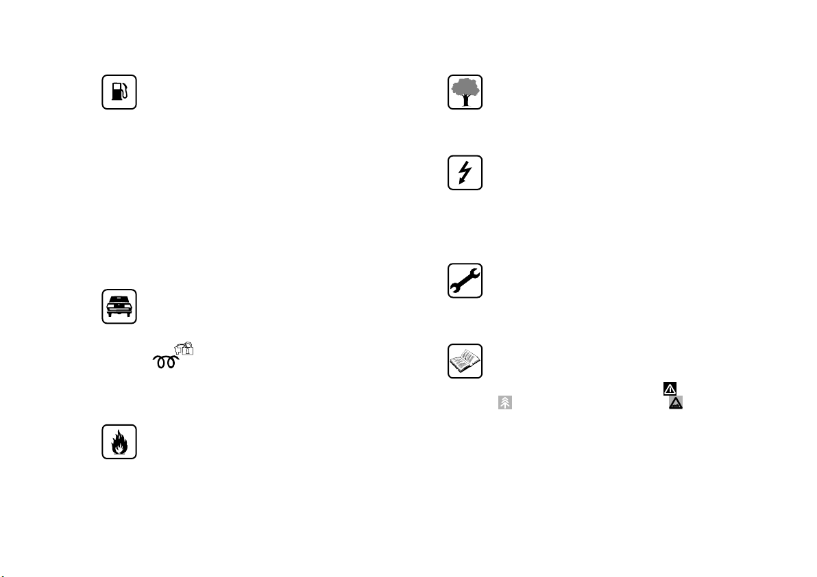
ESSENTIAL INFORMATION!
REFUELLING
Petrol engines: only refuel with unleaded petrol
with octane rating (RON) not less than 95 in
compliance with the European specification
EN228.
The use of petrol that does not conform to the
above-mentioned specification will cause the
EOBD warning light to switch on and the
irregular operation of the engine.
Diesel engines: only refuel with diesel for
motor vehicles in compliance with the European
specification EN590. The use of other products
or mixtures may damage the engine beyond
repair and consequently invalidate the warranty.
STARTING THE ENGINE
Make sure that the handbrake is engaged; place
the gear lever in neutral. Fully depress the clutch
pedal, without pressing the accelerator, then
turn the ignition key to MAR-ON and wait for
the
ignition key to AVV and release it as soon as
the engine starts.
PARKING ON FLAMMABLE MATERIAL
The catalytic converter develops high
temperatures during operation. Do not park the
car on grass, dry leaves, pine needles or other
flammable material: fire hazard.
warning light to switch off (and
warning light for diesel versions); turn the
RESPECTING THE ENVIRONMENT
The car is fitted with a system that allows
continuous diagnosis of the components related
to emissions to ensure increased respect for
the environment.
ELECTRICAL ACCESSORIES
If, after buying the car, you decide to add
electrical accessories (with the risk of gradually
draining the battery), contact a Fiat Dealership.
They will calculate the overall electrical
requirement and check that the car’s electrical
system can support the required load.
SCHEDULED SERVICING
Correct maintenance of the car is essential for
ensuring that it maintains its performance and its
safety features, its environmental friendliness
and low running costs for a long time to come.
THE OWNER MANUAL CONTAINS…
… important information, advice and warnings
for correct use, driving safety and maintenance of
your car over time. Special attention must be
paid to the symbols provided (personal safety)
(environmental protection) (car integrity).
Page 7
GETTING TO KNOW YOUR CAR
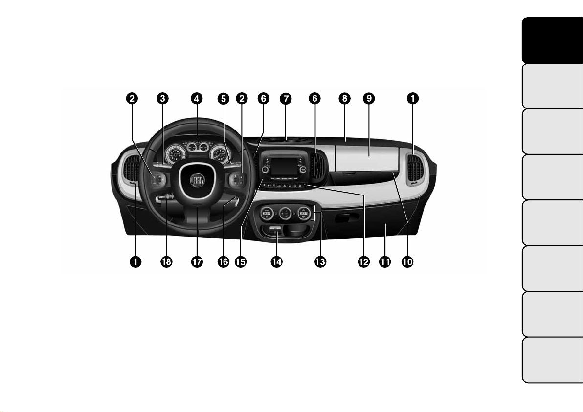
DASHBOARD
The presence and position of the controls, instruments and indicators may vary according to the different
versions.
fig. 1
1. Adjustable and directable air diffusers 2. Radio controls on the steering wheel (for versions/markets, where provided)
3. Exterior light control stalk 4. Instrument panel 5. Windscreen wiper/rear window wiper/trip computer control stalk
6. Adjustable and directable centre air vents 7. Fixed upper air vent 8. Passenger front airbag 9. Upper glove
compartment (for versions/markets, where provided the compartment may be conditioned) 10. Storage compartment
11. Lower glove compartment 12. Control buttons 13. Heating/ventilation system or manual climate control (for
versions/markets, where provided) or automatic dual zone climate control (for versions/markets, where provided)
14. USB port/AUX socket (for versions/markets, where provided) 15.
vided) or radio system setup 16. Ignition switch 17. Driver front airbag 18. Cruise Control/Speed Limiter lever (for
versions/markets, where provided)
UConnect® (for versions/markets, where pro-
F0Y0042
GETTING TO
KNOW YOUR CAR
SAFETY
STARTING AND
DRIVING
WARNING LIGHTS
AND MESSAGES
IN AN EMERGENCY
SERVICING AND
MAINTENANCE
TECHNICAL
SPECIFICATIONS
INDEX
3
Page 8
GETTING TO
KNOW YOUR CAR
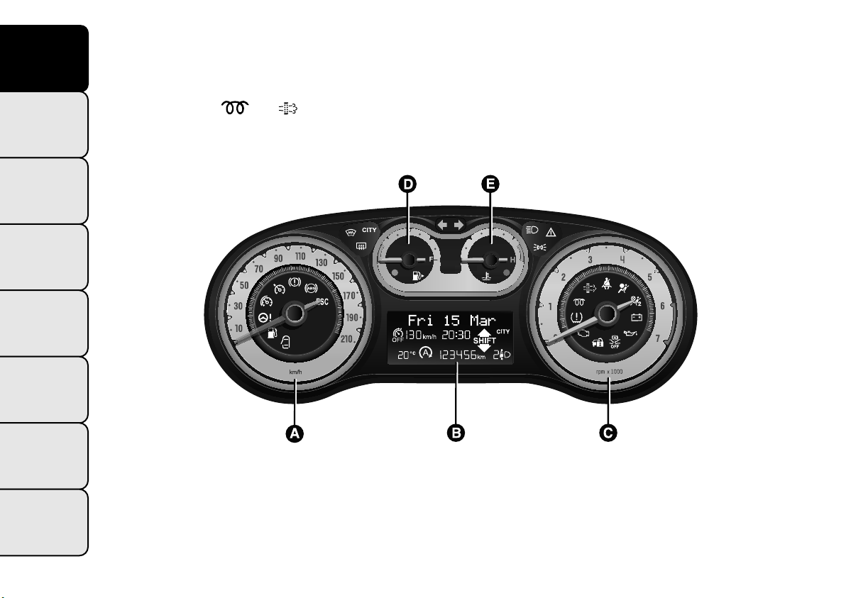
CONTROL PANEL AND
INSTRUMENTS
Instrument background colour and type may vary according to the version.
The warning lights
speed (red range on the rev counter) corresponds to 5000 rpm.
SAFETY
VERSIONS WITH MULTIFUNCTION DISPLAY
STARTING AND
DRIVING
WARNING LIGHTS
AND MESSAGES
IN AN EMERGENCY
SERVICING AND
MAINTENANCE
TECHNICAL
SPECIFICATIONS
A. Speedometer (speed indicator) B. Multifunction display C. Rev counter D. Fuel level gauge with reserve warning light
E. Engine coolant temperature gauge with overheating warning light
fig. 2
and are only present on Diesel versions. On diesel versions, the maximum engine
F0Y1107
INDEX
4
Page 9
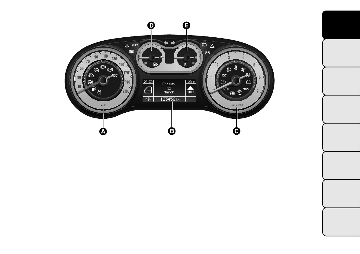
VERSIONS WITH RECONFIGURABLE MULTIFUNCTIONAL DISPLAY
GETTING TO
KNOW YOUR CAR
SAFETY
STARTING AND
DRIVING
WARNING LIGHTS
AND MESSAGES
fig. 3
A. Speedometer (speed indicator) B. Reconfigurable multifunction display C. Rev counter D. Fuel level gauge with reserve
warning light E. Engine coolant temperature gauge with overheating warning light
F0Y1108
IN AN EMERGENCY
SERVICING AND
MAINTENANCE
TECHNICAL
SPECIFICATIONS
INDEX
5
Page 10
GETTING TO
KNOW YOUR CAR
SAFETY
STARTING AND
DRIVING
WARNING LIGHTS
AND MESSAGES
IN AN EMERGENCY
SERVICING AND
MAINTENANCE
SPEEDOMETER (SPEED INDICATOR)
Shows the car speed (speedometer).
REV COUNTER
This indicates the engine rpm.
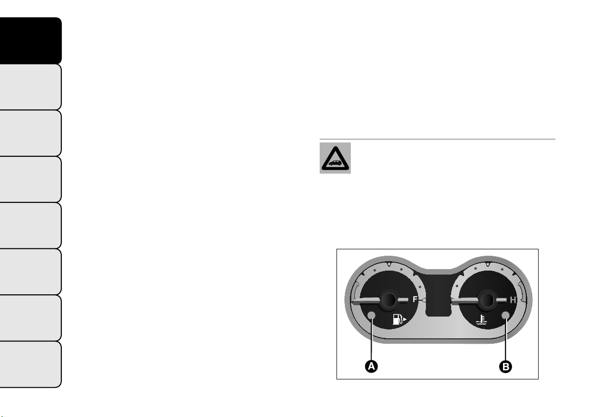
FUEL LEVEL GAUGE
This shows the amount of fuel left in the fuel tank.
E - tank empty
F - tank full
The warning light A fig. 4 (on certain versions
together with the message on the display) switches
on to indicate that approximately 6 to 8 litres of fuel
are left in the tank; in these circumstances refuel at
the earliest opportunity.
Do not travel with the fuel tank almost empty: the
gaps in fuel delivery could damage the catalyst.
IMPORTANT The needle will point to E and warning
light A will flash to indicate a fault in the system. If
this is the case, go to a Fiat Dealership to have
the system checked.
Under normal conditions, the needle assumes
different positions within the scale depending on the
usage conditions.
C - Low engine coolant temperature.
H - High engine coolant temperature.
The warning light B fig. 4 may switch on (with a
message on the display for some versions) to indicate
that the coolant temperature is too high; in this
case, stop the engine and contact a Fiat Dealership.
If the needle for the engine coolant
temperature reaches the red area, stop
the engine immediately and contact a Fiat
Dealership.
TECHNICAL
SPECIFICATIONS
INDEX
6
ENGINE COOLANT TEMPERATURE
INDICATOR
The needle shows the temperature of the engine
coolant and starts supplying indications when the
fluid temperature exceeds approx. 50°C.
fig. 4
F0Y0118
Page 11
DISPLAY
The car may be provided with a multifunction or
reconfigurable multifunction display that shows useful
information, according to the previous settings,
when driving.
With the ignition key removed, the display activates
and shows the time and total milometer reading
(in km or miles) for a few seconds when a front door
is opened/closed.
NOTE With a very low outside temperature (below
0°C) it may take longer than normal for information
to appear on the display.
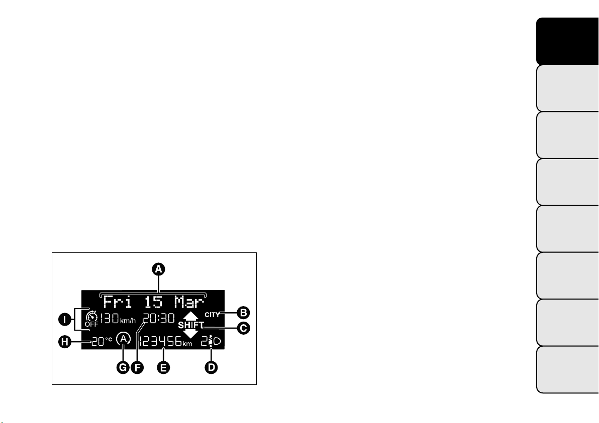
MULTIFUNCTION DISPLAY "STANDARD"
SCREEN
The following information is shown on the display
fig. 5:
Date
A
Activation of Dualdrive electric power steering
B
(CITY indication) or of ECO driving mode (ECO
indication)
Gear Shift Indicator (for versions/markets, where
C
provided)
Headlight alignment position (only with dipped
D
headlights on)
Odometer (display of distance travelled in
E
kilometres/miles)
Time (always displayed, even with key removed and
F
doors closed)
Start&Stop function indication (for versions/
G
markets where provided)
Outside temperature (for versions/markets, where
H
provided)
"Speed limiter" display (for versions/markets, where
I
provided)
GETTING TO
KNOW YOUR CAR
SAFETY
STARTING AND
DRIVING
WARNING LIGHTS
AND MESSAGES
IN AN EMERGENCY
SERVICING AND
MAINTENANCE
fig. 5
TECHNICAL
SPECIFICATIONS
INDEX
F0Y1101
7
Page 12
GETTING TO
KNOW YOUR CAR
SAFETY
STARTING AND
DRIVING
WARNING LIGHTS
AND MESSAGES
IN AN EMERGENCY
SERVICING AND
MAINTENANCE
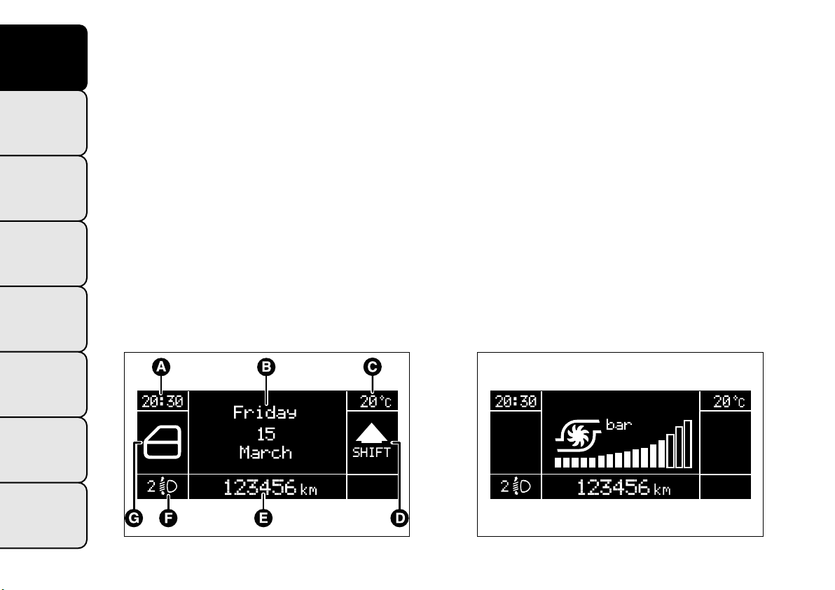
RECONFIGURABLE MULTIFUNCTION
DISPLAY "STANDARD" SCREEN
Versions without "Speed Limiter"
The following information appears on the display
fig. 6:
Time
A
Date or trip distance display in kilometres (or
B
miles)
Outside temperature (for versions/markets, where
C
provided)
Gear Shift Indicator (for versions/markets, where
D
provided)
Odometer (display of distance travelled in
E
kilometres/miles)
Headlight alignment position (only with dipped
F
headlights on)
Car status indication (e.g. doors open, possible ice
G
on road, etc.)
On some versions the display shows the turbine
pressure fig. 7.
TECHNICAL
SPECIFICATIONS
INDEX
8
fig. 6
F0Y1102
fig. 7
F0Y0186
Page 13
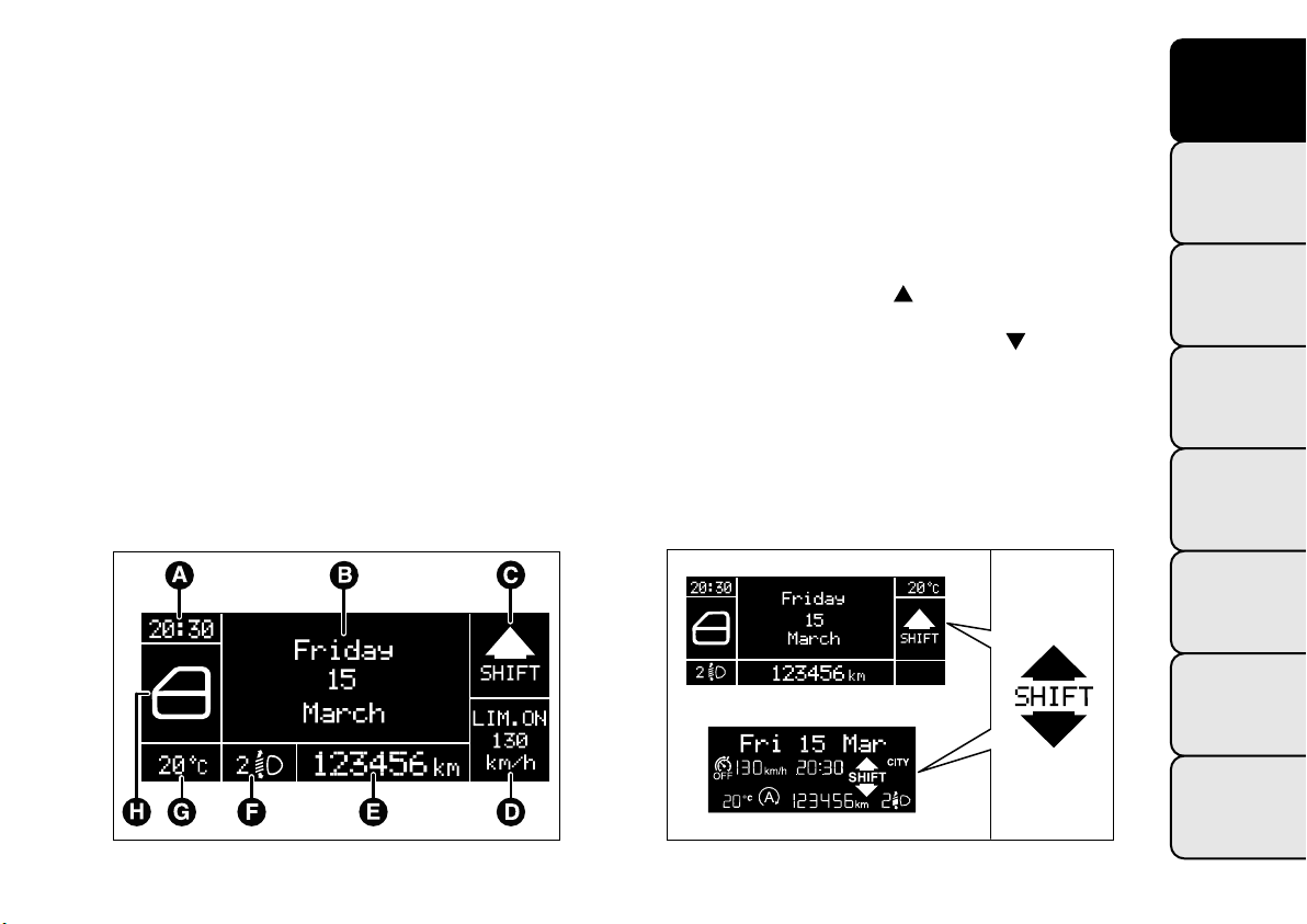
Versions with "Speed Limiter"
(for versions/markets, where provided)
The following information appears on the display
fig. 8:
Time
A
Date or trip distance display in kilometres (or
B
miles)
Gear Shift Indicator (for versions/markets, where
C
provided) or Start&Stop function indication (for
versions/markets, where provided)
"Speed limiter" display (for versions/markets,
D
where provided)
Odometer (display of distance travelled in
E
kilometres/miles)
Headlight alignment position (only with dipped
F
headlights on)
Outside temperature (for versions/markets, where
G
provided)
Car status indication (e.g. doors open, possible ice
H
on road, etc.)
GEAR SHIFT INDICATOR
The GSI (Gear Shift Indicator) system advises the
driver to change gear through a specific indication on
the instrument panel fig. 9.
Through the GSI, the driver is notified that changing
gear will allow a reduction in fuel consumption.
When the SHIFT UP icon (
SHIFT) is shown on the
display, the GSI is advising the driver to engage a
higher gear, while the SHIFT DOWN (
SHIFT) icon
advises the driver to engage a lower gear.
The indication on the instrument panel remains on
until the driver changes gear or the driving
conditions return to a situation where changing gear
is not required to reduce consumption.
GETTING TO
KNOW YOUR CAR
SAFETY
STARTING AND
DRIVING
WARNING LIGHTS
AND MESSAGES
IN AN EMERGENCY
SERVICING AND
MAINTENANCE
fig. 8
F0Y1103
fig. 9
TECHNICAL
SPECIFICATIONS
INDEX
F0Y1104
9
Page 14
GETTING TO
KNOW YOUR CAR
SAFETY
STARTING AND
DRIVING
WARNING LIGHTS
AND MESSAGES
IN AN EMERGENCY
SERVICING AND
MAINTENANCE
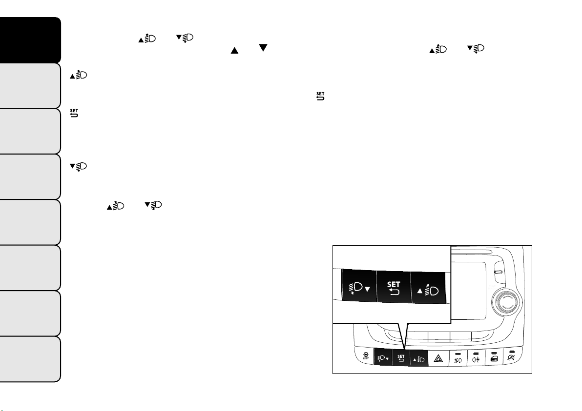
CONTROL BUTTONS
NOTE Buttons
the following pages. The buttons are
and fig. 10 are described in
and on
some versions.
To scroll up through the screen and the related
options or to increase the displayed value.
Press briefly to access the menu and/or go to next
screen or confirm the desired menu selection.
Hold down to go back to the standard screen.
To scroll down through the displayed menu and the
related options or to decrease the value displayed.
Buttons
and activate different functions
according to the following situations:
❒ within the menu, they allow you to scroll up and
down;
❒ during setting operations, they increase or
decrease the displayed value.
SETUP MENU
The menu comprises a series of options which can
be selected using buttons
and to access the
different selection and setting operations (Setup)
indicated below. Some options have a submenu.
The menu can be activated by briefly pressing the
button.
The menu comprises the following options:
❒ MENU
❒ LIGHTING
❒ HEADLIGHT ALIGNMENT (for versions/markets,
where provided)
❒ SPEED BEEP
❒ HEADLIGHT SENSOR (for versions/markets
where provided)
❒ CORNERING LIGHTS (for versions/markets,
where available)
TECHNICAL
SPECIFICATIONS
INDEX
10
fig. 10
F0Y0035
Page 15
❒ RAIN SENSOR (for versions/markets, where
provided)
❒ TRIP B ACTIVATION/DATA
❒ SET TIME
❒ SET DATE
❒ AUTOCLOSE
❒ MEASUREMENT UNIT
❒ LANGUAGE
❒ WARNINGS VOLUME
❒ BELT BUZZER
❒ SERVICE
❒ AIRBAG/PASSENGER BAG (for versions/markets,
where provided)
❒ DAYTIME RUNNING LIGHTS (for versions/
markets, where provided)
❒ CITY BRAKE C./COLLISION MITIGATION
(for versions/markets, where provided)
❒ EXIT MENU
Selecting an option from t he main menu without a
submenu:
❒ briefly press the
option to be set;
❒ press buttons
select the new setting;
❒ briefly press the
and to go back to the same main menu option
selected previously.
Selecting an option from t he main menu with a
submenu:
❒ briefly press the
submenu option;
❒ press buttons
scroll through all the submenu options;
❒ briefly press the
submenu option and to open the relevant setup
menu;
❒ press buttons
select the new setting for this submenu option;
❒ briefly press button
at the same time go back to the previously
selected menu option.
button to select the main menu
or (with single presses) to
button to store the new setting
button to display the first
or (with single presses) to
button to select the displayed
or (with single presses) to
to store the new setting and
GETTING TO
KNOW YOUR CAR
SAFETY
STARTING AND
DRIVING
WARNING LIGHTS
AND MESSAGES
IN AN EMERGENCY
SERVICING AND
MAINTENANCE
TECHNICAL
SPECIFICATIONS
INDEX
11
Page 16
GETTING TO
KNOW YOUR CAR
SAFETY
STARTING AND
DRIVING
WARNING LIGHTS
AND MESSAGES
IN AN EMERGENCY
SERVICING AND
MAINTENANCE
TECHNICAL
SPECIFICATIONS
INDEX
MENU ITEMS
Note With UConnect® system (for versions/
markets where provided), some Menu items are
shown on the display of the latter and not on the
instrument panel display.
Menu
This option allows you to access the Setup Menu.
Press the
Menu items.
Hold down the
screen.
Lighting
(Interior light adjustment)
(with side lights on only)
With the side lights on, this function is used to set
the brightness of the instrument panel, UConnect®
system controls (for versions/markets where provided) and automatic climate control system controls
(for versions/markets where provided) to 8 levels.
Proceed as follows to adjust the brightness:
❒ press button
flashes on the display;
❒ press button
brightness level;
❒ press the
screen or hold the button down to return to the
standard screen without saving.
or button to select the various
button to return to the standard
briefly. The level set previously
or to set the required
button briefly to return to the menu
Note On versions with reconfigurable multifunction
display adjustment can be made both with lights off
("daytime" mode brightness level) and with lights
on ("nighttime" mode brightness level).
Headlamp alignment (Headlamp alignment
corrector position adjustment)
(for versions/markets, where provided)
This function allows the headlamp alignment
corrector position to be adjusted (on 4 levels).
To carry out the adjustment, proceed as follows:
❒ press button
flashes on the display;
❒ press button
❒ press the
screen or hold the button down to return to the
standard screen without storing.
Speed Beep (Speed limit)
This function is used to set the car speed limit (km/h
or mph); the driver is immediately alerted when
this limit is exceeded.
To set the desired speed limit, proceed as follows:
❒ briefly press the
the text "Speed Beep";
❒ press button
activation (On) or deactivation (Off);
❒ if the function is on, press
desired speed limit and then press to confirm.
briefly. The level set previously
or to adjust the position;
button briefly to return to the menu
button: the display will show
or to select speed limit
or to select the
12
Page 17
Note Setting is possible between 30 and 200 km/h,
or 20 and 125 mph, according to the previously
set unit. See the "Measurement unit adjustment
(Measurement unit)" paragraph described below. The
setting will increase/decrease by 5 units each time
button
/ button to automatically increase/decrease
the setting rapidly. Complete the adjustment with
single presses of the button when you approach the
desired value.
❒ press the
screen or hold the button down to return to the
standard screen without storing.
To cancel the setting, proceed as follows:
❒ briefly press the
display;
❒ press button
❒ press the
screen or give the button a long press to return
to the standard screen without storing.
Headlight sensor
(Automatic headlight/dusk sensor sensitivity
adjustment)
(for versions/markets, where provided)
This function is used to turn the headlights on or off
according to external light conditions.
/ is pressed. Hold down the
button briefly to return to the menu
button: "On" will flash on the
: "Off" will flash on the display;
button briefly to return to the menu
The dusk sensor sensitivity can be adjusted according
to 3 levels (level 1 = minimum sensitivity, level 2 =
medium sensitivity, level 3 = maximum sensitivity);
the greater the sensitivity set, the less the external
light variation needed to turn on the lights (e.g. with
a setting on level 3 at sunset the headlights switch
on earlier than in levels 1 and 2).
Proceed as follows to set:
❒ press button
flashes on the display;
❒ press the
adjustment;
❒ press the
screen or hold the button down to return to the
standard screen without storing.
Cornering lights
(Activation/deactivation of cornering lights)
(for versions/markets, where provided)
This function activates/deactivates ("On"/"Off") the
cornering lights (see the description in the “Exterior
lights” paragraph).
Proceed as follows to activate/deactivate the lights:
❒ press button
the display, according to what has been previously
set;
❒ press
❒ press the
screen or hold the button down to return to the
standard screen without storing.
briefly. The level set previously
or button to make the
button briefly to return to the menu
briefly. "On" or "Off" flash on
or to make your choice;
button briefly to return to the menu
GETTING TO
KNOW YOUR CAR
SAFETY
STARTING AND
DRIVING
WARNING LIGHTS
AND MESSAGES
IN AN EMERGENCY
SERVICING AND
MAINTENANCE
TECHNICAL
SPECIFICATIONS
INDEX
13
Page 18
GETTING TO
KNOW YOUR CAR
SAFETY
STARTING AND
DRIVING
WARNING LIGHTS
AND MESSAGES
IN AN EMERGENCY
SERVICING AND
MAINTENANCE
TECHNICAL
SPECIFICATIONS
INDEX
Rain sensor
(Rain sensor sensitivity adjustment)
(for versions/markets, where provided)
This function allows you to adjust the rain sensor
sensitivity to 4 levels.
To set the required sensitivity level, proceed as
follows:
❒ press button
previously flashes on the display;
❒ press the
adjustment;
❒ press the
screen or hold the button down to return to the
standard screen without storing.
Activation/Trip B data
(ActivatingTrip B)
With this function it is possible to activate ("On") or
deactivate ("Off") the Trip B display (partial trip).
For more information see the "Trip computer"
paragraph.
For activation/deactivation, proceed as follows:
❒ press the
On or Off according to the previous setting;
❒ press the
adjustment;
❒ press the
screen or give the button a long press to return
to the standard screen without storing.
briefly. The sensitivity “level” set
or button to make the
button briefly to return to the menu
button briefly to make the display flash
or button to make the
button briefly to return to the menu
Time adjustment (Clock adjustment)
This function enables the clock to be set through
two submenus: “Time” and “Format”.
To carry out the adjustment, proceed as follows:
❒ press button
submenus "Time" and "Format";
❒ press the
the two submenus;
❒ once you have selected the submenu to be
changed, press the button
❒ if the "Time" submenu is selected and button
pressed briefly, "hours" will flash on the display.
Press the
adjustment;
❒ pressing the
flash on the display. Press the
to make the adjustment;
❒ if the "Format" submenu is selected and button
is pressed briefly, the display mode will flash
on the display. Press the
select "12h" or "24h" mode. When you have
carried out the required settings, briefly press the
button to go back to the submenu screen or
hold the button down to go back to the main
menu screen without storing the new settings.
Hold down the
standard screen or to the main menu according to
the menu items where you are in.
briefly. The display shows the two
or button to switch between
briefly;
or button to make the
button briefly again: the "minutes"
or button
or button to
button again to return to the
is
14
Page 19
IMPORTANT The setting will increase or decrease
by one unit each time the button
pressed. Keeping the button pressed causes an
automatic rapid speed increase/decrease. Complete
the setting by briefly pressing the button when
you approach the required value.
Set date (Setting the date)
Using this function it is possible to update the date
(year - month - day).
To carry out the adjustment, proceed as follows:
❒ press button
display;
❒ press the
adjustment;
❒ press button
display;
❒ press the
adjustment;
❒ press button
display;
❒ press the
adjustment;
❒ press the
screen or give the button a long press to return
to the standard screen without storing.
briefly. The "year" flashes on the
or button to make the
briefly. The "month" flashes on the
or button to make the
briefly. The "day" flashes on the
or button to make the
button briefly to return to the menu
or is
IMPORTANT The setting will increase or decrease
by one unit each time the button
pressed. Keeping the button pressed causes an
automatic rapid speed increase/decrease. Complete
the setting by briefly pressing the button when
you approach the required value.
Autoclose
(Automatic door lock operation with car
running)
If this function is On, it automatically locks the doors
when a speed of 20 km/h is exceeded.
Proceed as follows to activate or deactivate this
function:
❒ press button
display, according to what has been previously set;
❒ press
❒ press the
submenu screen or hold the button down
to return to the main menu screen without saving;
❒ hold down the
standard screen or to the main menu according
to the menu items where you are in.
briefly. "On" or "Off" flash on the
or to make your choice;
button briefly to return to the
button again to return to the
or is
GETTING TO
KNOW YOUR CAR
SAFETY
STARTING AND
DRIVING
WARNING LIGHTS
AND MESSAGES
IN AN EMERGENCY
SERVICING AND
MAINTENANCE
TECHNICAL
SPECIFICATIONS
INDEX
15
Page 20
GETTING TO
KNOW YOUR CAR
SAFETY
STARTING AND
DRIVING
WARNING LIGHTS
AND MESSAGES
IN AN EMERGENCY
SERVICING AND
MAINTENANCE
TECHNICAL
SPECIFICATIONS
Unit of measurement
(Setting the unit of measurement)
With this function it is possible to set the units
through three submenus: "Distances",
"Consumption" and "Temperature".
To set the desired measurement unit, proceed as
follows:
❒ press button
three submenus;
❒ press button
three submenus;
❒ once you have selected the submenu to be
changed, press the button
❒ if the "Distances" submenu is selected and button
is pressed briefly, the display shows "km" or
"mi" depending on the previous setting;
❒ press
❒ if the "Consumption" submenu is selected and
button
"km/l", "l/100km" or "mpg" depending on
the previous setting. If the measurement unit set
for "Distances" is "km", the display allows the
measurement unit ("km/l" or "l/100km") for
Consumption to be set. If the measurement unit
set for "Distances" is "mi", the display will show
Consumption in "mpg";
❒ press
briefly. The display will show the
or to scroll through the
briefly;
or to make your choice;
is pressed briefly, the display shows
or to make your choice;
❒ if the "Temperature" submenu is selected and
button
or "°F" depending on the previous setting;
❒ press
Once the required settings are made, briefly press
button
the button down to return to the main menu screen
without storing.
Hold down the
standard screen or to the main menu according to
the menu items where you are in.
Language (Language selection)
Display messages can be set to be shown in different
languages: Italian, German, English, Spanish, French,
Portuguese, Polish, Dutch, Turkish (the list varies
according to the market).
To set the desired language, proceed as follows:
❒ press button
previously flashes on the display;
❒ press
❒ press the
screen or hold the button down to return to the
standard screen without storing.
is pressed briefly, the display shows "°C"
or to make your choice;
to go back to the submenu screen or hold
button again to return to the
briefly. The “language” set
or to make your choice;
button briefly to return to the menu
INDEX
16
Page 21
Warnings volume
(Adjusting the alert/warning acoustic signal
volume)
With this function the volume of the buzzer which
accompanies the display of any failure/warning can be
adjusted to 8 levels.
To set the desired volume, proceed as follows:
❒ press button
previously flashes on the display;
❒ press
❒ press the
screen or hold the button down to return to the
standard screen without storing.
Seat belt buzzer
(SBR buzzer reactivation)
(for versions/markets, where provided)
This function can only be displayed after a Fiat
Dealership has deactivated the SBR system (see
paragraph “SBR system” in the “Safety” chapter).
To reactivate this function, proceed as follows:
❒ press the
display. Press the
will appear;
❒ press the
submenu screen or hold the button down
to return to the main menu screen without saving.
briefly. The volume “level” set
or to make your choice;
button briefly to return to the menu
button briefly; "Off" will flash on the
or button and "On"
button briefly to return to the
Service (Scheduled servicing)
With this function it is possible to view information
on mileage or time intervals for servicing.
With the Service function it is also possible to view
the interval (in kilometres or miles) before the
next engine oil change is due.
To consult this display, proceed as follows:
❒ press button
service interval in kilometres (km) or miles (mi)
according to the previous setting (see the "Units of
measurement" paragraph);
❒ press the
screen or hold it down to return to the standard
screen.
Note The “Scheduled Servicing Plan” requires the
car to be serviced every 30,000 km (or 18,000 miles)
for petrol versions and every 35,000 km (or 21,000
miles) for diesel versions. This message is displayed
automatically - when the key is turned to MAR-ON 2,000 km (or equivalent value in miles) before these
deadlines and reappears every 200 km (or equivalent
value in miles). Below 200 km servicing indications
are more frequent. The display will be in km or
mi depending on the measurement unit settings.
When one of the next scheduled deadlines is
approaching, the word “Service” will appear on the
display, followed by the number of kilometres or
miles left, when the key is turned to MAR-ON.
Contact a Fiat Dealership. The operations in the
“Scheduled servicing plan” will be performed and the
message will be reset.
briefly. The display shows the
button briefly to return to the menu
GETTING TO
KNOW YOUR CAR
SAFETY
STARTING AND
DRIVING
WARNING LIGHTS
AND MESSAGES
IN AN EMERGENCY
SERVICING AND
MAINTENANCE
TECHNICAL
SPECIFICATIONS
INDEX
17
Page 22
GETTING TO
KNOW YOUR CAR
SAFETY
STARTING AND
DRIVING
WARNING LIGHTS
AND MESSAGES
IN AN EMERGENCY
SERVICING AND
MAINTENANCE
TECHNICAL
SPECIFICATIONS
INDEX
Airbag/Passenger bag
(Activation/deactivation of passenger side
front airbag and side bag for pelvis, chest and
shoulder protection - for versions/markets,
where provided)
This function allows the passenger airbag to be
activated / deactivated.
Proceed as follows:
❒ press the
pass: Off" (to deactivate) or "Bag pass: On" (to
activate) is displayed by pressing buttons
, press the button again;
❒ a confirmation request message will appear on the
display;
❒ by pressing the
confirm activation/deactivation) or "No" (to
cancel);
❒ press the
the selection is displayed and you return to the
menu screen; Hold down the button to return to
the standard screen without storing.
Daytime running lights (D.R.L.)
(for versions/markets, where provided)
This function can be used to activate/deactivate the
daytime running lights.
Proceed as follows to activate or deactivate this
function:
❒ press button
submenu;
button and, after the message "Bag
and
or buttons select "Yes" (to
button briefly; a message confirming
briefly. The display shows a
❒ press button
display, according to what has been previously set;
❒ press
❒ press the
submenu screen or hold the button down
to return to the main menu screen without saving;
❒ hold down the
standard screen or to the main menu according
to the menu items where you are in.
City Brake Control - "Collision Mitigation"
(for versions/markets, where provided)
This function allows to activate ("On") or de-activate
("Off") the City Brake Control - "Collision
Mitigation" system.
To adjust proceed as follows:
❒ press button
display, according to what has been previously set;
❒ a confirmation request message will appear on the
display;
❒ by pressing the
confirm activation/deactivation) or "No" (to
cancel);
❒ press the
the selection is displayed and you return to the
menu screen; Hold down the button to return to
the standard screen without storing.
When the system is deactivated the dedicated
warning light in the instrument panel switches on
(see chapter "Warning lights and Messages").
briefly. "On" or "Off" flash on the
or to make your choice;
button briefly to return to the
button again to return to the
briefly. "On" or "Off" flash on the
or buttons select "Yes" (to
button briefly; a message confirming
18
Page 23

Exit menu
The last function closing the cycle of settings listed in
the menu screen.
Pressing the
to the standard screen without saving.
Press the
option (Lighting).
button briefly will return the display
button to return to the first menu
TRIP COMPUTER
GENERAL INFORMATION
The Trip computer is used to display information on
car operation when the key is turned to MAR-ON.
This function allows you to define two separate trips
called “Trip A” and “Trip B” where the car's
"complete journeys" are monitored in a reciprocally
independent manner.
Both journeys can be reset (reset - start of a new
journey).
“Trip A” is used to display the figures relating to:
❒ Outside temperature (for versions/markets, where
provided)
❒ Range
❒ Distance travelled A
❒ Average consumption A
❒ Instantaneous consumption
❒ Average speed A
❒ Trip time A (driving time).
“Trip B” may be used to display the figures relating
to:
❒ Distance travelled B
❒ Average consumption B
❒ Average speed B
❒ Trip time B (driving time).
GETTING TO
KNOW YOUR CAR
SAFETY
STARTING AND
DRIVING
WARNING LIGHTS
AND MESSAGES
IN AN EMERGENCY
SERVICING AND
MAINTENANCE
TECHNICAL
SPECIFICATIONS
INDEX
19
Page 24

GETTING TO
KNOW YOUR CAR
SAFETY
STARTING AND
DRIVING
WARNING LIGHTS
AND MESSAGES
IN AN EMERGENCY
SERVICING AND
MAINTENANCE
Note “Trip B” may be disabled (see “Activating Trip
B”). “Range” and “Instantaneous fuel consumption"
parameters cannot be reset.
VALUES DISPLAYED
Outside temperature (for versions/markets, where
provided)
Indicates the temperature outside the passenger
compartment.
Range
This indicates the approximate distance which can be
travelled with the amount of fuel present in the
tank.“----”will appear on the display in the
following cases:
❒ range value lower than 50 km (or 30 mi)
❒ car parked with engine running for a long period.
IMPORTANT The range value variation can be
affected by several factors: driving style, type of route
(motorway, urban, mountain roads, etc.), conditions
of use (load, tyre pressures, etc.). Trip planning
must therefore take the above into account.
Average consumption
Shows the approximate average fuel consumption
since the start of the new journey.
Instantaneous consumption
This value shows the fuel consumption. The value is
constantly updated. The display will show “----”
if the car is parked with the engine running.
Average speed
This shows the car average speed as a function of the
overall time elapsed since the start of the new
mission.
Trip time
Shows the time elapsed since the start of a new
journey.
IMPORTANT If there is no information, the Trip
computer displays "----"inplaceofthevalue.
When normal operating condition is restored,
calculation of different units will restart regularly. No
values displayed before the failure will be reset nor
will a new mission be started.
TECHNICAL
SPECIFICATIONS
INDEX
20
Distance travelled
Shows the distance covered since the start of the
new journey.
Page 25
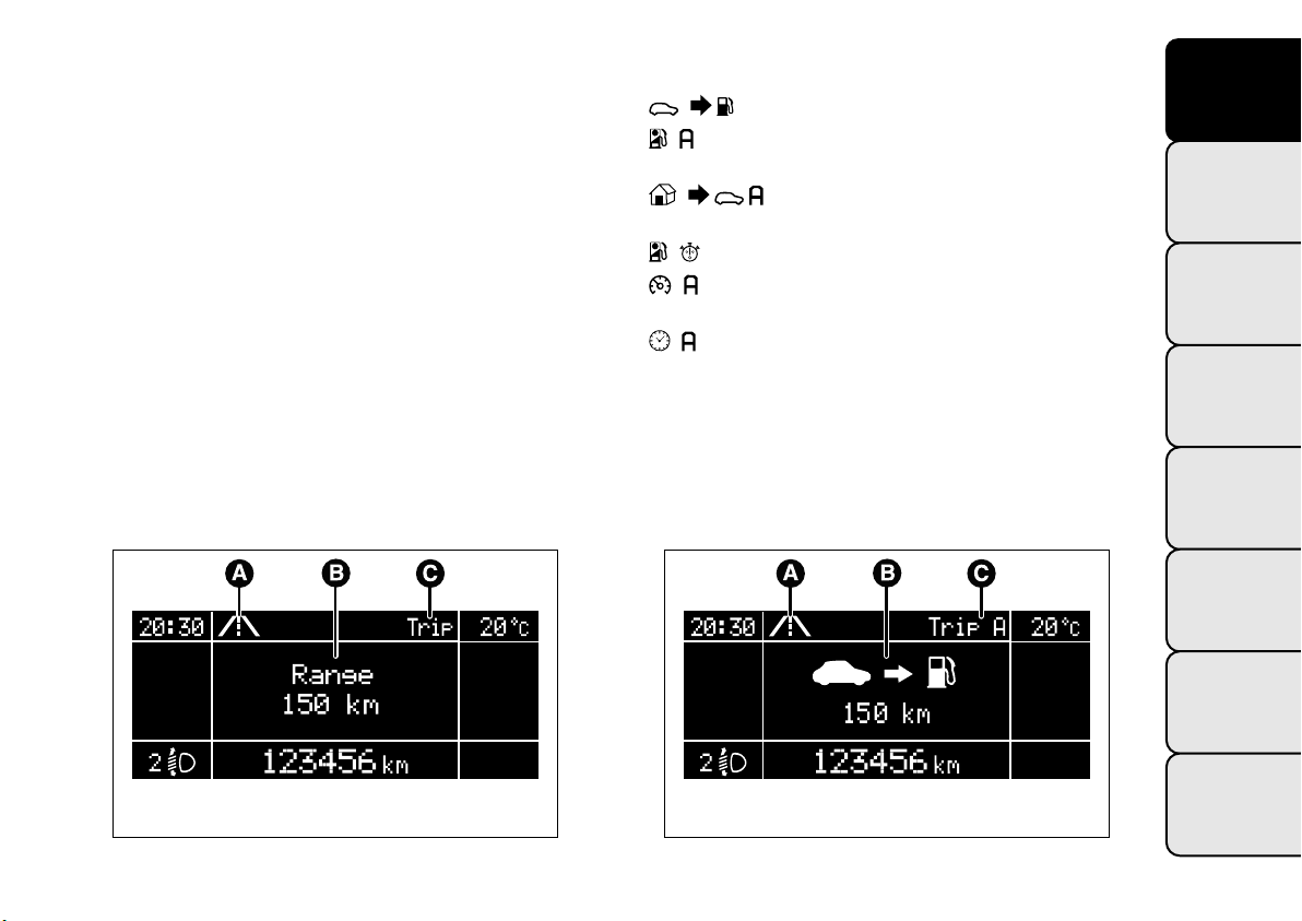
DISPLAYED INFORMATION
The displays shown below are reported as an
example: for further information refer to the
"Display" paragraph in this chapter.
Each time a value is displayed, the following
information is shown fig. 11:
❒ A - animated icon in the upper part;
❒ B - name, value and unit of measure of the
selected parameter (e.g. "Range 150 km");
❒ C - the word "Trip" (or "Trip A" or "Trip B").
After a few seconds the name and value of the
selected parameter are replaced by an icon fig. 12.
The icons relating to the various parameters are the
following:
❒
❒
"Range";
"Average consumption A” (if Trip A is active,
or “B” if Trip B is active);
❒
"Distance" (if Trip A is active, or “B” if
Trip B is active);
❒
❒
"Instantaneous consumption";
"Average speed A” (if Trip A is active, or “B”
if Trip B is active);
❒
"Trip time" (if Trip A is active, or “B” if Trip B
is active);
GETTING TO
KNOW YOUR CAR
SAFETY
STARTING AND
DRIVING
WARNING LIGHTS
AND MESSAGES
IN AN EMERGENCY
SERVICING AND
MAINTENANCE
fig. 11
F0Y1105
fig. 12
TECHNICAL
SPECIFICATIONS
INDEX
F0Y1106
21
Page 26
GETTING TO
KNOW YOUR CAR
SAFETY
STARTING AND
DRIVING
WARNING LIGHTS
AND MESSAGES
IN AN EMERGENCY
SERVICING AND
MAINTENANCE
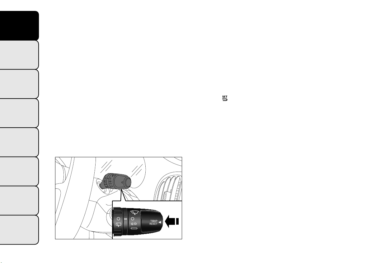
TRIP BUTTON
This is located on the right-hand stalk fig. 13. With
the ignition key turned to MAR, this button allows
you to view the previously described parameters and
also reset them to begin a new mission:
❒ short press: display various readings;
❒ long press: reset readings and start a new mission.
New mission
This begins after a reset:
❒ “manual” resetting by the user, by pressing the
relevant button;
❒ "automatic" resetting, when the "Trip distance"
reaches 99999.9 km or when the "Travel time"
reaches 999:59 (999 hours and 59 minutes);
❒ after disconnection/reconnection of the battery.
IMPORTANT The reset operation when “Trip A” or
“Trip B” details are being displayed resets the
information associated with the function displayed.
Start of journey procedure
With ignition key at MAR, press and hold the TRIP
button for more than 2 seconds to reset.
Exit Trip
You can automatically exit the TRIP function once all
the values have been displayed or by holding the
button
down for more than 1 second.
TECHNICAL
SPECIFICATIONS
INDEX
22
fig. 13
F0Y0045
Page 27

SYMBOLS
Special coloured labels have been attached near to or
on some of the components of your car. These
labels bear symbols that remind you of the
precautions to be taken with regard to that
particular component.
Under the bonnet there is also a label that
summarises all the symbols.
THE FIAT CODE SYSTEM
To further protect your car from theft, it has been
fitted with an engine immobilising system. It is
automatically activated when the ignition key is
removed.
There is an electronic device in each key which can
identify the signal emitted, when the engine is
started, from an aerial built into the ignition switch.
The signal is the "password", different every time the
vehicle is started, through which the control unit
recognises the key and enables starting.
GETTING TO
KNOW YOUR CAR
SAFETY
STARTING AND
DRIVING
OPERATION
Each time the vehicle is started turning the ignition
key to MAR-ON, the Fiat CODE system control unit
sends an acknowledgement code to the engine
control unit to deactivate the immobiliser. The code
is sent only if the Fiat CODE system control unit
has acknowledged the code received from the key.
Each time the ignition key is turned to STOP, the Fiat
CODE system deactivates the functions of the
engine management control unit.
If, during starting, the code is not correctly
recognised, the
instrument panel.
In this case, turn the key to STOP and then to
MAR-ON; if it is still locked, try again with the other
keys that come with the vehicle. Contact a Fiat
Dealership if you still cannot start the engine.
warning light switches on in the
WARNING LIGHTS
AND MESSAGES
IN AN EMERGENCY
SERVICING AND
MAINTENANCE
TECHNICAL
SPECIFICATIONS
INDEX
23
Page 28
GETTING TO
KNOW YOUR CAR
SAFETY
STARTING AND
DRIVING
WARNING LIGHTS
AND MESSAGES
IN AN EMERGENCY
SERVICING AND
MAINTENANCE
Warning light switching on while driving
If the
warning light switches on, this means that
the system is running a self-diagnosis (for example
for a voltage drop). Should the fault persist, contact a
Fiat Dealership.
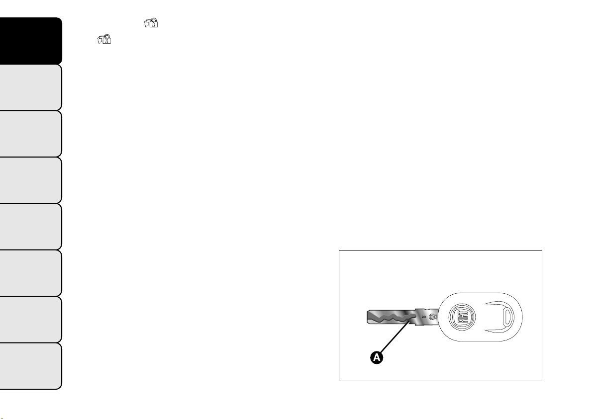
THE KEYS
KEY WITHOUT REMOTE CONTROL
The metal insert A fig. 14 enables:
❒ the ignition switch;
❒ the door lock.
To request duplicates of the key, go to a Fiat
Dealership, taking an ID document and the car
ownership documents.
TECHNICAL
SPECIFICATIONS
INDEX
24
fig. 14
F0Y0117
Page 29
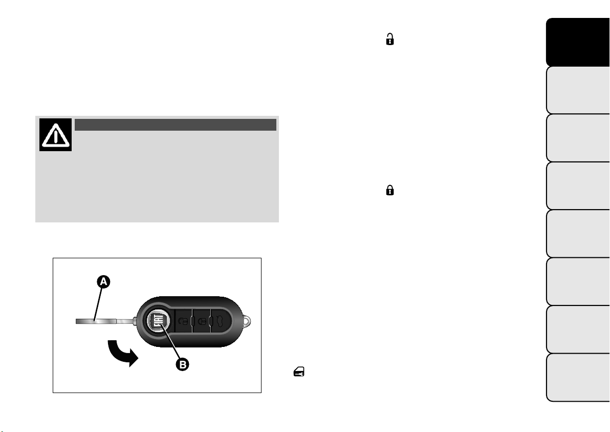
KEY WITH REMOTE CONTROL
(for versions/markets, where provided)
The metal insert A fig. 15 of the key operates:
❒ the ignition switch;
❒ the door lock.
Press button B to open/close the metal insert.
WARNING
Button B should only be pressed when
the key is away from the body, in
particular from the eyes and from objects that
can be spoilt (e.g. clothes). Do not leave the key
unattended to avoid the button being
accidentally pressed while it is being handled,
e.g. by a child.
fig. 15
F0Y0019
Unlocking the doors and the tailgate
Briefly press button
: for unlocking of doors and
luggage compartment, timed switching-on of internal
roof lights and double flashing of direction indicators
(for versions/markets, where provided).
The doors are unlocked automatically if the fuel
cut-off system intervenes.
Once the doors are locked, if one or more doors or
the luggage compartment are not closed correctly,
the LED and direction indicators start flashing
quickly.
Locking the doors and the tailgate
Briefly press button
: for locking of doors and
luggage compartment, with switching-off of roof light
and single flashing of direction indicators (for
versions/markets, where provided).
If one or more doors are open, the doors will not be
locked. This is indicated by a rapid flashing of the
direction indicators (for versions/markets, where
provided). The doors will be locked if the tailgate is
open however.
When a speed of over 20 km/h is reached, the doors
are automatically locked if this specific function has
been set (only on versions with multi-function
reconfigurable display).
When the doors are locked from outside the car
(using the remote control), the LED above the
button will switch on for a few seconds and then
start flashing (deterrent function).
GETTING TO
KNOW YOUR CAR
SAFETY
STARTING AND
DRIVING
WARNING LIGHTS
AND MESSAGES
IN AN EMERGENCY
SERVICING AND
MAINTENANCE
TECHNICAL
SPECIFICATIONS
INDEX
25
Page 30
GETTING TO
KNOW YOUR CAR
SAFETY
STARTING AND
DRIVING
WARNING LIGHTS
AND MESSAGES
When the doors are locked from inside the car (by
pressing the
button) the LED will remain on
constantly.
Opening the luggage compartment
Press the
button to open the luggage
compartment using the remote control.
The direction indicators will flash twice to indicate
that the luggage compartment has been opened.
The electronic components inside the key
may be damaged if the key is subjected
to strong shocks. In order to ensure
complete efficiency of the electronic devices
inside the key, it should never be exposed
to direct sunlight.
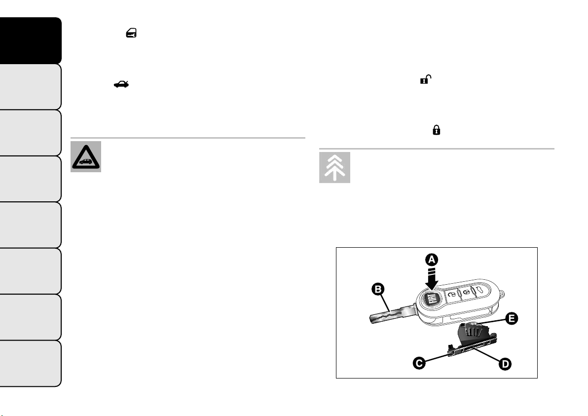
REPLACINGTHE BATTERY IN THE KEY
WITH REMOTE CONTROL
To replace the battery, proceed as follows:
❒ press button A fig. 16 and open the metal insert B;
❒ turn the screw C to using a fine bit screwdriver;
❒ take out the battery case D and replace the
battery E making sure that polarities are correct;
❒ refit the battery case D inside the key and lock it
turning the screw C to
.
Used batteries should be disposed of, as
specified by law, in the special containers,
otherwise take them to a Fiat Dealership,
which will deal with their disposal.
IN AN EMERGENCY
REQUEST FOR ADDITIONAL REMOTE
CONTROLS
The system can recognise up to 8 remote controls.
SERVICING AND
MAINTENANCE
Should a new remote control be necessary, go to
a Fiat Dealership, taking an ID document and the car
ownership documents.
TECHNICAL
SPECIFICATIONS
INDEX
26
fig. 16
F0Y0018
Page 31

SAFE LOCK DEVICE
(for versions/markets, where provided)
This safety device inhibits the operation of the
interior door handles and the door locking/unlocking
button.
It thereby prevents the opening of the doors from
inside the passenger compartment, serving as an
obstacle to break-in attempts (e.g. broken window).
We recommend that you activate the device each
time you park your car.
Activating the device
The device is enabled on all the doors by quickly
double-pressing the
button on the key.
The direction indicators flash 3 times and the LED
above the
fig. 17 button flashes to indicate that
the device has been activated. If one or more of the
doors are not closed correctly, the device will not
activate, thus preventing a person from getting stuck
inside the passenger compartment by entering the
car through, and then closing, the open door.
Deactivating the device
The device deactivates automatically:
❒ carrying out the door unlocking operation
(pressing the
button on the key with remote
control or turning the metal insert of the key
without remote control in the driver side door
lock);
❒ by turning the ignition key to the MAR position.
WARNING
Once the safe lock system is engaged, it
is impossible to open the doors from
inside the car.Therefore, before getting out of
the car check that there is no-one left on board.
GETTING TO
KNOW YOUR CAR
SAFETY
STARTING AND
DRIVING
WARNING LIGHTS
AND MESSAGES
IN AN EMERGENCY
SERVICING AND
MAINTENANCE
fig. 17
TECHNICAL
SPECIFICATIONS
INDEX
F0Y0039
27
Page 32

GETTING TO
KNOW YOUR CAR
SAFETY
STARTING AND
DRIVING
WARNING LIGHTS
AND MESSAGES
IN AN EMERGENCY
SERVICING AND
MAINTENANCE
IGNITION DEVICE
The key can be turned to 3 different positionsfig. 18:
❒ STOP: engine off, key can be removed, steering
column locked. Some electrical devices (e.g. sound
system, central door locking system, etc.) can
operate;
❒ MAR: driving position. All electrical devices are
enabled;
❒ AVV: engine start-up.
The ignition switch is fitted with a safety system that
requires the ignition key to be turned back to STOP
if the engine does not start, before the starting
operation can be repeated.
WARNING
If the ignition device has been tampered
with (e.g. an attempted theft), have it
checked by a Fiat Dealership before driving
again.
WARNING
Always remove the key when you leave
your car to prevent someone from
accidentally operating the controls. Remember
to engage the handbrake. Engage 1
st
gear if
the car is parked uphill or reverse if the car is
parked downhill. Never leave children
unattended in the car.
TECHNICAL
SPECIFICATIONS
INDEX
28
fig. 18
F0Y0044
Page 33

STEERING LOCK
Engagement: when the key is in position STOP,
remove the key and turn the steering wheel until it is
locked.
Disengagement: move the steering wheel slightly
as you turn the ignition key to MAR.
SEATS
WARNING
All adjustments must be made with the
car stationary.
GETTING TO
KNOW YOUR CAR
SAFETY
WARNING
It is absolutely forbidden to carry out
any after-market operation involving
steering system or steering column
modifications (e.g.: installation of anti-theft
device) that could badly affect performance and
safety, invalidate the warranty and also result
in non-compliance of the car with typeapproval requirements.
WARNING
Never remove the key while the car is
moving.The steering wheel will lock
as soon as it is turned.This holds true for cars
being towed as well.
The fabric upholstery of the seats has
been designed to withstand long-term
wear deriving from normal use of the car.
Some precautions are however required. Avoid
prolonged and/or excessive rubbing against
clothing accessories such as metal buckles and
Velcro strips which, by applying a high pressure on
the fabric in a small area, could cause it to
break, thereby damaging the upholstery.
STARTING AND
DRIVING
WARNING LIGHTS
AND MESSAGES
IN AN EMERGENCY
SERVICING AND
MAINTENANCE
TECHNICAL
SPECIFICATIONS
INDEX
29
Page 34

GETTING TO
KNOW YOUR CAR
SAFETY
FRONT SEATS
Lengthwise adjustment
Lift lever A fig. 19 (on the inner side of the seat) and
push the seat forwards or backwards: in driving
position your arms should rest on the rim of the
steering wheel.
Height adjustment
(for versions/markets, where provided)
Move lever B fig. 20 upwards or downwards to
achieve the required height.
IMPORTANT Carry out the adjustment while sitting
on the seat involved (driver side or passenger side).
STARTING AND
DRIVING
locked on the guides by trying to move it back
WARNING LIGHTS
AND MESSAGES
and forth. If the seat is not locked into place,
it may unexpectedly slide and cause the driver
to lose control of the car.
IN AN EMERGENCY
SERVICING AND
MAINTENANCE
TECHNICAL
SPECIFICATIONS
INDEX
30
WARNING
Once you have released the adjustment
lever, always check that the seat is
fig. 19
F0Y0218
fig. 20
F0Y0216
Page 35

Backrest angle adjustment
Operate lever C fig. 21 to adjust the backrest angle,
accompanying it with the movement of the torso
(operate the lever until the desired position is
reached, then release it).
Positioning the passenger seat as a table.
(for versions/markets, where provided)
Move the seat fully backwards by operating lever A
(see "Lengthwise adjustment"), operate lever C, fold
the backrest down to the cushion then release
lever C.
It is advisable to carry out this procedure from the
outside, with the left hand.
Before tilting the front passenger seat
table fully, remove any objects laid on it.
WARNING
Do not move the front passenger seat
table if a child is seated on the same or
sitting in the suitable child restraint system.
Electric lumbar adjustment
(for versions/markets, where provided)
With key at MAR-ON press button A fig. 22 to
operate the lumbar area supporting device for
regulating comfort level when driving.
Release the button when you reach the desired
position.
GETTING TO
KNOW YOUR CAR
SAFETY
STARTING AND
DRIVING
WARNING LIGHTS
AND MESSAGES
IN AN EMERGENCY
SERVICING AND
MAINTENANCE
fig. 21
F0Y0217
fig. 22
TECHNICAL
SPECIFICATIONS
INDEX
F0Y0215
31
Page 36

GETTING TO
KNOW YOUR CAR
SAFETY
STARTING AND
DRIVING
WARNING LIGHTS
AND MESSAGES
IN AN EMERGENCY
SERVICING AND
MAINTENANCE
Electric seat heating
(for versions/markets, where provided)
With the key turned to MAR-ON, press button B to
switch the function on/off.
When the function is enabled, the LED on the
button switches on.
IMPORTANT If this function is activated with engine
off the battery may run down.
Driver's side seat armrest
(for versions/markets, where provided)
On some versions the driver's side seat is equipped
with an armrest.
The armrest can be raised/lowered by acting in the
direction shown by the arrows (see fig. 23).
Storage compartment
Behind the front seat backrest there is a storage
compartment fig. 24.
TECHNICAL
SPECIFICATIONS
INDEX
32
fig. 23
F0Y0159
fig. 24
F0Y0270
Page 37

Ta bl e
(for versions/markets, where provided)
On some versions, behind the front seat backrest
there is a folding support surface A fig. 25 equipped
with cup/can holders. To fold the support surface
operate point B.
In the rear of the backrests there is also an object
retaining net C.
IMPORTANT Do not place objects heavier than 3 kg
on the supporting surface: for safety reasons the
supporting surface is detached from its housing when
subject to higher loads.
WARNING
Do not travel with the supporting
surface open: always make sure it is
correctly closed.
GETTING TO
KNOW YOUR CAR
SAFETY
STARTING AND
DRIVING
WARNING LIGHTS
AND MESSAGES
IN AN EMERGENCY
SERVICING AND
MAINTENANCE
fig. 25
TECHNICAL
SPECIFICATIONS
INDEX
F0Y0271
33
Page 38

GETTING TO
KNOW YOUR CAR
SAFETY
SLIDING AND FOLDING REAR SEATS
Lengthwise adjustment
Raise lever A fig. 26, gripping it in the central area
and push the seat forwards or backwards.
The two parts of the seat can be adjusted
individually.
To increase the room between seat and parcel shelf
grab tab C fig. 28 on the parcel shelf and secure it on
the magnetic device D, then operate lever B to
bring the backrest in the desired position.
STARTING AND
Backrest angle adjustment
DRIVING
Raise lever B fig. 27 and adjust the backrest angle,
accompanying it with the movement of the torso.
The backrest can be further folded to improve
WARNING LIGHTS
driving comfort.
AND MESSAGES
IN AN EMERGENCY
SERVICING AND
MAINTENANCE
TECHNICAL
SPECIFICATIONS
INDEX
34
fig. 26
F0Y0074
fig. 27
fig. 28
F0Y0259
F0Y0066
Page 39

Rear armrest
(for versions/markets, where provided)
To use the armrest fig. 29, lower it as shown in the
figure.
HEAD RESTRAINTS
FRONT
They are height-adjustable: to adjust them, operate
as follows.
Upwards adjustment: raise the head restraint until it
clicks into place.
Downwards adjustment: press button A fig. 30 and
lower the head restraint.
Proceed as follows to remove the head restraints:
❒ raise the head restraints to their maximum height;
❒ press buttons A and B (at the side of the two
head restraint supports), then remove the head
restraints by pulling them upwards.
GETTING TO
KNOW YOUR CAR
SAFETY
STARTING AND
DRIVING
WARNING LIGHTS
AND MESSAGES
IN AN EMERGENCY
SERVICING AND
MAINTENANCE
fig. 29
F0Y0163
fig. 30
TECHNICAL
SPECIFICATIONS
INDEX
F0Y0060
35
Page 40

GETTING TO
KNOW YOUR CAR
SAFETY
STARTING AND
DRIVING
WARNING LIGHTS
AND MESSAGES
IN AN EMERGENCY
SERVICING AND
MAINTENANCE
REAR
(for versions/markets, where provided)
Two height-adjustable head restraints are provided
for the rear seats. On some versions a head restraint
is also provided for the central seat.
Upwards adjustment: raise the head restraint until it
clicks into place.
Downwards adjustment: press button A fig. 31 and
lower the head restraint.
Proceed as follows to remove the head restraints:
❒ raise the head restraints to their maximum height;
❒ press buttons A and B fig. 31 at the side of the
two supports, then remove the head restraints
by pulling them upwards.
IMPORTANT If the rear seats are used, always set
the head restraints in the "completely raised"
position.
STEERING WHEEL
The steering wheel can be adjusted both axially and
vertically.
To adjust, move lever A fig. 32 downwards to
position 1, then adjust the steering wheel to the
most suitable position and lock it in position by
moving lever A to position 2.
WARNING
All adjustments must be carried out only
with the car stationary and engine off.
TECHNICAL
SPECIFICATIONS
INDEX
36
fig. 31
F0Y0061
fig. 32
F0Y0043
Page 41

WARNING
It is absolutely forbidden to carry out
any after-market operation involving
steering system or steering column
modifications (e.g. installation of anti-theft
device) that could badly affect performance and
safety, invalidate the warranty and also result
in the car not meeting type-approval
requirements.
REAR VIEW MIRRORS
INTERIOR MIRROR
The mirror is fitted with a safety device that causes
its release in the event of a violent impact with
the passenger.
Operate lever A fig. 33 to adjust the mirror into two
different positions: normal or anti-glare.
GETTING TO
KNOW YOUR CAR
SAFETY
STARTING AND
DRIVING
WARNING LIGHTS
AND MESSAGES
IN AN EMERGENCY
SERVICING AND
MAINTENANCE
fig. 33
TECHNICAL
SPECIFICATIONS
INDEX
F0Y0223
37
Page 42

GETTING TO
KNOW YOUR CAR
SAFETY
STARTING AND
DRIVING
WARNING LIGHTS
AND MESSAGES
IN AN EMERGENCY
SERVICING AND
MAINTENANCE
ELECTROCHROMIC INTERIOR MIRROR
(for versions/markets, where provided)
Some versions feature an electrochromic mirror
fig. 34 with an ON/OFF switch to activate/deactivate
the electrochromic function.
When reverse gear is engaged, the mirror is
automatically set for daytime use.
DOOR MIRRORS
Manual adjustment
From the inside of the car, operate lever A fig. 35 to
adjust the mirror.
TECHNICAL
SPECIFICATIONS
INDEX
38
fig. 34
F0Y0225
fig. 35
F0Y0275
Page 43

Electrical adjustment
(for versions/markets, where provided)
The mirrors can be adjusted only if the ignition key is
in MAR position.
To adjust proceed as follows:
❒ use device A fig. 36 to select the required mirror
(right or left);
❒ move device A to position B and manipulate it to
adjust the left door mirror;
❒ move device A to position D and manipulate it to
adjust the right door mirror.
Once you have finished the adjustment, return device
A to intermediate locking position C.
Manual folding
If necessary, fold the mirrors by moving them from
position 1 (open) to position 2 (closed) fig. 37.
IMPORTANT When driving the mirrors should
always be in position 1 (open).
GETTING TO
KNOW YOUR CAR
SAFETY
STARTING AND
DRIVING
WARNING LIGHTS
AND MESSAGES
IN AN EMERGENCY
SERVICING AND
MAINTENANCE
fig. 36
F0Y0250
fig. 37
TECHNICAL
SPECIFICATIONS
INDEX
F0Y0226
39
Page 44

GETTING TO
KNOW YOUR CAR
SAFETY
STARTING AND
DRIVING
WARNING LIGHTS
AND MESSAGES
IN AN EMERGENCY
SERVICING AND
MAINTENANCE
CLIMATE CONTROL
SIDE AIR DIFFUSERS
A fig. 38 - Adjustable and directable side air diffusers:
❒ use device B to adjust the vent to the required
position;
❒ turn wheel C to adjust the air flow.
D - Fixed side air diffuser.
UPPER AIR DIFFUSERS
A fig. 39 - Upper adjustable air diffuser. Turn wheel B
to adjust the air flow.
C - Fixed upper air diffuser.
CENTRAL AIR DIFFUSERS
A fig. 40 - Adjustable and directable central air
diffusers:
❒ use device B to adjust the vent to the required
position;
❒ turn wheel C to adjust the air flow.
fig. 39
F0Y0108
TECHNICAL
SPECIFICATIONS
INDEX
40
fig. 38
F0Y0107
fig. 40
F0Y0109
Page 45

CLIMATIC COMFORT
DIFFUSERS
GETTING TO
KNOW YOUR CAR
SAFETY
STARTING AND
DRIVING
WARNING LIGHTS
AND MESSAGES
IN AN EMERGENCY
fig. 41
1. Fixed upper diffuser 2. Adjustable side diffusers 3. Fixed diffusers for side windows 4. Adjustable centre air diffusers
5. Adjustable upper diffuser
F0Y0222
SERVICING AND
MAINTENANCE
TECHNICAL
SPECIFICATIONS
INDEX
41
Page 46

GETTING TO
KNOW YOUR CAR
SAFETY
STARTING AND
DRIVING
WARNING LIGHTS
AND MESSAGES
IN AN EMERGENCY
HEATING AND VENTILATION
CONTROLS
SERVICING AND
MAINTENANCE
TECHNICAL
SPECIFICATIONS
INDEX
42
fig. 42
F0Y0156
Page 47

A - Air temperature adjustment knob:
❒ blue section = cold air
❒ red section = hot air
B - air recirculation on/off button;
C - fan activation/adjustment knob:
❒ 0 = fan off
❒ 1-2-3-4 = fan speed
D - heated rear window on/off button;
E - air distribution knob:
air from central outlets and side vents
air from central outlets, side vents and front and
rear footwell vents
air only from front and rear footwell vents
air from front and rear footwell vents, to
windscreen and side windows
air outlet to windscreen and side windows
PASSENGER COMPARTMENT
VENTILATION/HEATING
To heat the passenger compartment, proceed as
follows:
❒ turn knob A to the red section;
❒ turn knob E to
❒ turn knob C to 4 (maximum fan speed).
Then operate the controls to maintain the desired
comfort conditions.
;
IMPORTANT When the engine is cold, it takes a few
minutes to achieve optimum passenger compartment
heating.
RAPID DEMISTING/DEFROSTING
This function activates rapid desisting/defrosting of
the windscreen and front side windows.
For rapid demisting/defrosting, proceed as follows:
❒ turn knob A to the red section;
❒ press button B and deactivate internal air
recirculation (LED on button off);
❒ turn knob C to 4 (maximum fan speed);
❒ turn knob E to
Window demisting
The climate control system is very useful in
preventing the windows from misting up in the event
of high levels of humidity.
In the event of considerable external humidity and/or
rain and/or large differences in temperature inside
and outside the passenger compartment, perform
the following preventive window demisting
procedure:
❒ turn knob A to the red section;
❒ press button B and deactivate internal air
recirculation (LED on button off);
.
GETTING TO
KNOW YOUR CAR
SAFETY
STARTING AND
DRIVING
WARNING LIGHTS
AND MESSAGES
IN AN EMERGENCY
SERVICING AND
MAINTENANCE
TECHNICAL
SPECIFICATIONS
INDEX
43
Page 48

GETTING TO
KNOW YOUR CAR
SAFETY
STARTING AND
DRIVING
WARNING LIGHTS
AND MESSAGES
IN AN EMERGENCY
SERVICING AND
MAINTENANCE
TECHNICAL
SPECIFICATIONS
INDEX
❒ turn knob E to with the possibility of moving it
to position
❒ turn knob C to the 2
if misting does not occur;
nd
speed (advised speed). It is
possible to select a different speed according to
your own judgement.
HEATED REAR WINDOW
DEMISTING/DEFROSTING
Press button D (
) to activate/deactivate the
function.
The activation of the function is indicated by the LED
on the button itself switching on. The function is
automatically deactivated after 20 minutes.
For versions/markets where provided, press the
button to activate demisting/defrosting of door
mirrors and windscreen (for versions/markets, where
provided).
IMPORTANT Do not affix stickers to the inside of
the heated rear window over the heating filaments,
to avoid damage that might cause them to stop
working properly.
INTERNAL AIR RECIRCULATION
Press button B (
) so that the LED on the
button switches on. It is advisable to switch internal
air recirculation on while standing in traffic or in
tunnels to prevent the introduction of polluted air.
Do not use the function for a long time, particularly
if there are many passengers on board, to prevent
the windows from misting up.
IMPORTANT Internal air recirculation makes it
possible to reach the required heating or cooling
conditions more quickly depending on the mode
selected. Do not use the internal air recirculation
function on rainy/cold days as it would considerably
increase the possibility of the windows misting.
AIR DISTRIBUTION SELECTION
Turn knob E to manually select one of the five
possible air distribution settings in the passenger
compartment:
Air flow to the windscreen, front side window
and front/rear footwell diffusers.
Air flow to the front/rear footwell diffusers. This
air distribution allows the passenger
compartment to be heated quickly.
Air flow distributed between central and side
dashboard vents and front/rear footwell vents.
Air flow to central/side dashboard vents
(passenger’s body).
Air flow to windscreen and side windows.
44
Page 49

MANUAL CLIMATE CONTROL
SYSTEM
CONTROLS
GETTING TO
KNOW YOUR CAR
SAFETY
STARTING AND
DRIVING
fig. 43
°C
°F
°C
°F
WARNING LIGHTS
AND MESSAGES
IN AN EMERGENCY
F0Y0041
SERVICING AND
MAINTENANCE
TECHNICAL
SPECIFICATIONS
INDEX
45
Page 50

GETTING TO
KNOW YOUR CAR
SAFETY
STARTING AND
DRIVING
WARNING LIGHTS
AND MESSAGES
IN AN EMERGENCY
SERVICING AND
MAINTENANCE
TECHNICAL
SPECIFICATIONS
A - Air temperature adjustment knob:
❒ blue section = cold air
❒ red section = hot air
B - air recirculation on/off button;
C - fan activation/adjustment knob:
❒ 0 = fan off
❒ 1-2-3-4 = fan speed
D - climate control system compressor on/off
button;
E - heated rear window on/off button;
F - air distribution knob:
air from central outlets and side vents
air from central outlets, side vents and front and
rear footwell vents
air only from front and rear footwell vents
air from front and rear footwell vents, to
windscreen and side windows
air outlet to windscreen and side windows
CLIMATE CONTROL SYSTEM (cooling)
To cool the passenger compartment, proceed as
follows:
❒ turn knob A to the blue section;
❒ press button B to enable internal air recirculation
(LED on button on);
❒ turn knob F to
❒ press button D to activate climate control system
and turn knob C to at least 1 (1
;
st
speed). For
rapid cooling, turn knob C to 4 (maximum fan
speed).
IMPORTANT According to particular outside
environmental conditions, the climate control system
activates recirculation automatically (for versions/
markets, where additional heater provided).
Reduction in cooling
❒ turn knob A clockwise to increase the
temperature;
❒ press button B to deactivate internal air
recirculation (LED on button off);
❒ turn knob C to reduce the fan speed.
PASSENGER COMPARTMENT HEATING
To heat the passenger compartment, proceed as
follows:
❒ turn knob A to the red section;
❒ press button B to enable internal air recirculation
(LED on button on);
❒ turn knob F to
❒ turn knob C to at least 1 (1
;
st
speed). For rapid
heating, turn knob C to 4 (maximum fan speed).
INDEX
46
Page 51

Reduction in heating
❒ turn knob A anticlockwise to decrease the
temperature;
❒ press button B to deactivate internal air
recirculation (LED on button off);
❒ turn knob C to reduce the fan speed.
IMPORTANT When the engine is cold, it takes a few
minutes to achieve optimum passenger compartment
heating.
RAPID DEMISTING/DEFROSTING
This operation allows the windscreen and front side
windows to be rapidly demisted/defrosted.
For rapid demisting/defrosting, proceed as follows:
❒ turn knob A to the red section;
❒ turn knob C to 4 (maximum fan speed);
❒ turn knob F to
.
IMPORTANT In this condition, the climate control
system deactivates the recirculation function (LED
on button B off) and activates the compressor (LED
on button D on). The purpose of this automatic
operation is to prevent the window misting up.
Window demisting
The climate control system is very useful in
preventing the windows from misting up in the event
of high levels of humidity.
In the event of considerable external humidity and/or
rain and/or large differences in temperature inside
and outside the passenger compartment, perform
the following preventive window demisting
procedure:
❒ turn knob A to the red section;
❒ turn knob F to
to position
❒ turn knob C to the 2
with the possibility of moving it
if misting does not occur;
nd
speed.
HEATED REAR WINDOW
DEMISTING/DEFROSTING
Press button E (
) to turn the function on/off.
The activation of the function is indicated by the LED
on the button itself switching on. The function is
automatically deactivated after 20 minutes.
For versions/markets where provided, press the
button to activate demisting/defrosting of door
mirrors and heated windscreen (for versions/
markets, where provided).
IMPORTANT Do not affix stickers to the inside of
the heated rear window over the heating filaments,
to avoid damage that might cause them to stop
working properly.
GETTING TO
KNOW YOUR CAR
SAFETY
STARTING AND
DRIVING
WARNING LIGHTS
AND MESSAGES
IN AN EMERGENCY
SERVICING AND
MAINTENANCE
TECHNICAL
SPECIFICATIONS
INDEX
47
Page 52

GETTING TO
KNOW YOUR CAR
SAFETY
INTERNAL AIR RECIRCULATION
Press button B (
button switches on. It is advisable to switch internal
air recirculation on while standing in traffic or in
tunnels to prevent the introduction of polluted air.
Do not use the function for a long time, particularly
if there are many passengers on board, to prevent
the windows from misting up.
) so that the LED on the
Selecting the footwell/windscreen or only windscreen
distribution activates the climate control system
compressor (LED on A/C button on) and the air
recirculation is set to "outside air" (LED on button B
off). This logic guarantees optimum visibility at the
windows. The user can always set air recirculation
and climate control system compressor.
START&STOP
STARTING AND
DRIVING
WARNING LIGHTS
AND MESSAGES
IN AN EMERGENCY
SERVICING AND
MAINTENANCE
TECHNICAL
SPECIFICATIONS
IMPORTANT Internal air recirculation makes it
possible to reach the required heating or cooling
conditions more quickly depending on the mode
selected. Do not use the internal air recirculation
function on rainy/cold days as it would considerably
increase the possibility of the windows misting.
AIR DISTRIBUTION SELECTION
Turn knob F to manually select one of the five
possible air distribution settings in the passenger
compartment:
INDEX
48
Manual climate control system
If the Start&Stop function is activated (engine off
when the car speed is zero), the system keeps the air
flow selected by the user.
In these conditions, the passenger compartment
cooling and heating cannot be guaranteed, as the
compressor stops with the engine coolant pump.
The Start&Stop function can be deactivated, to
enhance the operation of the climate control system,
by pressing the dedicated button on the dashboard.
Air flow to the windscreen, front side window
and front/rear footwell diffusers.
Air flow to the front/rear footwell diffusers. This
air distribution allows the passenger
compartment to be heated quickly.
Air flow distributed between central and side
dashboard diffusers and front/rear footwell
diffusers.
Air flow to central/side dashboard vents
(passenger’s body).
Air flow to windscreen and side windows.
Page 53

ADDITIONAL ELECTRIC HEATER
(for versions/markets, where provided)
The additional electric heater ensures more rapid
passenger compartment heating.
It activates in cold weather conditions, if the
following conditions are verified:
❒ outside temperature low;
❒ engine coolant temperature low;
❒ engine on;
❒ fan speed set to 1
st
speed;
❒ knob A turned completely clockwise to red
section.
The heater is switched off when at least one of the
conditions above is no longer verified.
SYSTEM MAINTENANCE
In winter, the climate control system must be turned
on at least once a month for about 10 minutes.
Have the system inspected at a Fiat Dealership
before the summer.
The system uses R134a coolant which
does not pollute the environment in t he
event of accidental leakage. Under no
circumstances use R12 fluid, which is
incompatible with the components of the system.
GETTING TO
KNOW YOUR CAR
SAFETY
STARTING AND
DRIVING
WARNING LIGHTS
AND MESSAGES
Note The power of the electric heater is modulated
according to the battery voltage.
IN AN EMERGENCY
SERVICING AND
MAINTENANCE
TECHNICAL
SPECIFICATIONS
INDEX
49
Page 54

GETTING TO
KNOW YOUR CAR
SAFETY
STARTING AND
DRIVING
WARNING LIGHTS
AND MESSAGES
IN AN EMERGENCY
SERVICING AND
MAINTENANCE
AUTOMATIC DUAL ZONE CLIMATE
CONTROL SYSTEM
(for versions/markets, where provided)
CONTROLS
fig. 44
F0Y0034
TECHNICAL
SPECIFICATIONS
INDEX
50
Page 55

A - driver side temperature adjustment knob;
B - internal air recirculation on/off button;
C - heated rear window and thermal comfort
windscreen on/off button (for versions/markets,
where available);
D - climate control system compressor on/off
button;
E - climate control system on/off button;
F - fan speed adjustment knob;
G - fan speed indicator LED;
H - air distribution selection buttons;
I - MAX-DEF function (rapid defrosting/demisting of
front windows), heated rear window and heated
door mirrors (for versions/markets, where provided)
activation button;
L - passenger side temperature adjustment knob;
M - driver/passenger side MONO function activation
button (alignment of set temperatures);
N - AUTO function activation button (automatic
operation).
DESCRIPTION
The automatic dual zone climate control system
regulates the air temperatures in the passenger
compartment in two zones: driver side and
passenger side.
The system maintains comfort inside the passenger
compartment and compensates for possible
variations in external climate conditions.
The climate control system can recognise extremely
cold (or extremely hot) conditions in the passenger
compartment and consequently provide optimal
management of the system’s capabilities.
Note The reference temperature is 22°C for
optimal comfort management.
The automatically controlled parameters and
functions are:
❒ air temperature at the driver/front passenger side
vents;
❒ air distribution at the driver/front passenger side
vents;
❒ fan speed (continuous variation of the air flow);
❒ compressor engagement (for cooling/dehumidifying
the air);
❒ air recirculation.
All these functions can be adjusted manually by
operating the system, selecting one or more
functions and modifying their parameters.
Automatic control of the functions will be
suspended: the system will only override the settings
for safety reasons.
Manual selections always take priority over automatic
ones and are stored until the AUTO button is
pressed or the system itself intervenes for specific
safety reasons.
GETTING TO
KNOW YOUR CAR
SAFETY
STARTING AND
DRIVING
WARNING LIGHTS
AND MESSAGES
IN AN EMERGENCY
SERVICING AND
MAINTENANCE
TECHNICAL
SPECIFICATIONS
INDEX
51
Page 56

GETTING TO
KNOW YOUR CAR
SAFETY
STARTING AND
DRIVING
WARNING LIGHTS
AND MESSAGES
IN AN EMERGENCY
SERVICING AND
MAINTENANCE
TECHNICAL
SPECIFICATIONS
INDEX
The amount of air introduced into the passenger
compartment is not affected by car speed; it is
regulated by the fan, which is controlled
electronically.
The air temperature is always automatically
controlled according to the temperature set on the
display (except for when the system is off or in
certain conditions when the compressor is
not running).
The system allows the following to be set or adjusted
manually:
❒ driver/passenger side air temperature;
❒ fan speed (continuous variation);
❒ air distribution to 7 positions;
❒ compressor enablement;
❒ rapid defrosting/demisting function;
❒ air recirculation;
❒ heated rear window;
❒ system deactivation.
The climate control system detects the
passenger compartment temperature
using a mean radiant temperature sensor
located in the interior rear view mirror and
protected by a specific cover. Obstructing the
field of view of this sensor with any object could
cause the climate control system to operate
with less than optimal efficiency.
SWITCHING ON THE CLIMATE CONTROL
SYSTEM
The climate control system can be switched on in
different ways: it is advisable to press the AUTO
button and turn the knobs to set the desired
temperatures.
In this way the system operates completely
automatically to adjust the temperature, quantity and
distribution of the air introduced into the passenger
compartment. It also manages the air recirculation
function and the activation of the air conditioning
compressor.
During automatic operation, you can change the set
temperatures, air distribution and fan speed at any
time by using the relevant buttons or knobs: the
system will automatically change the settings to
adjust to the new requirements.
During completely automatic operation (AUTO),
varying the air flow and/or distribution (which are
not displayed) causes the AUTO function LED
to disappear and the system to operate in MANUAL
mode (displaying both the flow and distribution
requested).
When the compressor is deactivated, the AUTO
operation remains active only if the system can
guarantee in-car comfort. Otherwise, the system
switches to MANUAL mode (the set temperatures
will flash on the display). The fan speed is the same in
all the zones of the passenger compartment.
52
Page 57

ADJUSTING THE AIR TEMPERATURE
Turn the A or L knob clockwise or anticlockwise to
adjust the air temperature in the front left (knob
A) or right (knob L) zone of the passenger
compartment.
The set temperatures are shown on the displays.
Press the MONO button to align the air
temperature between the two zones.
Turn the L knob to return to the separate
management of air temperatures in the two zones.
Turning the knobs completely in one direction or the
other activates the "HI" (maximum heating) or
"LO" (maximum cooling) functions respectively.
To deactivate these functions, turn the temperature
knob to the desired temperature.
AIR DISTRIBUTION SELECTION
By pressing buttons H (
set one of the 7 possible air distributions manually:
Air flow to the windscreen and front side
window diffusers to demist/defrost them.
Air flow at central and side dashboard vents to
ventilate the chest and the face during the hot
season.
Air flow to the front and rear footwell diffusers.
This air distribution setting heats the passenger
compartment most quickly, giving a prompt
sensation of warmth.
/ / ), it is possible to
Air flow distributed between footwell
diffusers (hotter air) and central and side
dashboard vents (cooler air). This distribution
setting is useful in spring and autumn on
sunny days.
Air flow distributed between footwell
diffusers and windscreen and front side
window defrosting/demisting diffusers. This
distribution setting allows the passenger
compartment to be warmed effectively and
prevents the windows from misting.
Air flow distribution between windscreen
demisting/defrosting diffusers and side and
central dashboard vents. This allows air to be
sent to the windscreen in conditions of
strong sunlight.
Air flow distribution to all diffusers on
the car.
Note Air always flows from the side dashboard
diffusers: it is, however, possible to interrupt the air
flow by operating the wheel located near the
corresponding vents.
In AUTO mode, the climate control system
automatically manages air distribution (the LEDs on
buttons H are off).
When set manually, the air distribution is indicated
by the LEDs on the selected buttons switching on.
GETTING TO
KNOW YOUR CAR
SAFETY
STARTING AND
DRIVING
WARNING LIGHTS
AND MESSAGES
IN AN EMERGENCY
SERVICING AND
MAINTENANCE
TECHNICAL
SPECIFICATIONS
INDEX
53
Page 58

GETTING TO
KNOW YOUR CAR
SAFETY
STARTING AND
DRIVING
WARNING LIGHTS
AND MESSAGES
IN AN EMERGENCY
SERVICING AND
MAINTENANCE
TECHNICAL
SPECIFICATIONS
INDEX
54
In combined function mode, functions are enabled
together with those already set when the relevant
button is pressed. If a button whose function is
already active is pressed, the operation is cancelled
and the corresponding LED switches off.
To restore automatic control of the air distribution
after a manual selection, press the AUTO button.
ADJUSTING THE FAN SPEED
Turn knob F to increase/decrease the fan speed.
The speed is indicated by the LEDs G on the knob F
switching on.
❒ maximum fan speed = all LEDs lit;
❒ minimum fan speed = one LED lit.
The fan can only be excluded if the climate control
system compressor has been switched off by pressing
button D.
IMPORTANT To restore automatic control of the fan
speed after a manual adjustment, press the AUTO
button.
AUTO BUTTON
When the AUTO button is pressed (LED on button
lit) the climate control system automatically adjusts
the following settings in the corresponding zones:
❒ quantity and distribution of the air introduced into
the passenger compartment
❒ climate control system compressor
❒ air recirculation
cancelling all previous manual adjustments.
This is indicated by the LED on the AUTO button
switching on.
If the AUTO button is pressed when the AUTO LED
is on, the system switches to completely manual
mode; it displays the current flow and distribution
status, which will no longer be managed
automatically.
If a manual intervention is made on at least the air
distribution or on the fan speed, the LED switches
off to indicate that the system is no longer
controlling all functions automatically.
Deactivating the compressor results in the
deactivation of automatic operation only if the
system is no longer able to guarantee comfort
conditions (which depend on the set temperature).
IMPORTANT Should the system no longer be able to
guarantee the required temperature set in various
passenger compartment zones, the set temperature
value will flash for a few seconds on the display.
To restore automatic system control after one or
more manual adjustments, press the AUTO button.
Page 59

MONO BUTTON
Press the MONO button (LED on button lit) to align
the passenger side air temperature with that of the
driver side.
This function makes temperature regulation easier
when the driver is travelling alone.
Turn knob L to set the passenger side temperature
and return to separate air temperature management.
AIR RECIRCULATION
The air recirculation is managed according to the
following operating logics:
❒ forced activation (air recirculation always on):
indicated by the LED on button B
❒ forced deactivation (air recirculation always off, air
intake from the outside), signalled by the LED on
button B
Forced activation/deactivation can be selected by
pressing button B
When button
system automatically activates internal air
recirculation (LED on button B on)
It is still possible to activate outside air recirculation
(LED on the button off) and vice versa, by pressing
button B
In automatic operation, recirculation is managed
automatically by the system according to outside
environmental conditions.
switching off.
.
is pressed, the climate control
.
;
IMPORTANT The engagement of the recirculation
system makes it possible to reach the required
heating/cooling conditions faster. It is, however,
inadvisable to use it on rainy/cold days as it would
considerably increase the possibility of the windows
misting up inside (especially if the climate control
system is off). When the outside temperature is low,
recirculation is forced off (air drawn in from the
outside) to prevent the windows from misting up.
It is inadvisable to use internal air
recirculation when the outside
temperature is low, since the windows
could mist up rapidly.
GETTING TO
KNOW YOUR CAR
SAFETY
STARTING AND
DRIVING
WARNING LIGHTS
AND MESSAGES
IN AN EMERGENCY
SERVICING AND
MAINTENANCE
TECHNICAL
SPECIFICATIONS
INDEX
55
Page 60

GETTING TO
KNOW YOUR CAR
SAFETY
STARTING AND
DRIVING
WARNING LIGHTS
AND MESSAGES
IN AN EMERGENCY
SERVICING AND
MAINTENANCE
CLIMATE CONTROL SYSTEM
COMPRESSOR
Press button D to activate/deactivate the
compressor (activation is indicated by the LED on
the button switching on).
The system remembers that the compressor has
been switched off, even after the engine has stopped.
When the compressor is switched off the system
deactivates air recirculation to prevent the windows
from misting up. In this case, if the system is capable
of maintaining the required temperature, the AUTO
LED does not switch off.
The temperatures will instead flash for a few seconds
and the AUTO LED will switch off if the required
temperature cannot be maintained.
To restore automatic control of compressor
engagement, press button C again or press the
AUTO button.
With compressor off:
❒ if the outside temperature is higher than the set
one, the climate control system will not be able
to satisfy the request. The temperature values will
then flash on the display for a few seconds to
indicate this;
❒ the fan speed can be reset manually.
With the compressor on and the engine running,
manual ventilation cannot be lower than the
minimum speed (only one LED lit).
IMPORTANT With the compressor off, air cannot
be introduced to the passenger compartment with a
temperature lower than the outside temperature.
Moreover, under certain environmental conditions,
windows could mist rapidly since the air is not
dehumidified.
TECHNICAL
SPECIFICATIONS
INDEX
56
Page 61

RAPID WINDOW DEMISTING/
DEFROSTING (MAX-DEF function)
Press the
the windscreen and side window demisting/
defrosting function.
The climate control system carries out the following
operations:
❒ switches on the air conditioning compressor when
environmental conditions are suitable;
❒ switches air recirculation off;
❒ sets maximum air temperature (HI) in both zones;
❒ sets fan speed according to the engine coolant
temperature;
❒ directs air flow to windscreen and front side
windows diffusers;
❒ activates the heated rear window;
❒ activates the heated windscreen (for versions/
markets, where provided);
❒ displays the fan speed (LED G lit).
button to activate (LED on button on)
IMPORTANT The MAX-DEF function remains on for
about 3 minutes from when the engine coolant
reaches the appropriate temperature.
When the function is activated, the LED on the
AUTO button switches off. With the function
activated the only possible manual adjustments are
adjusting the fan speed and turning the heated rear
window off.
When the B, C, or AUTO buttons are pressed, the
climate control system will deactivate the MAX-DEF
function.
Selecting the footwell/windscreen or only windscreen
distribution activates the climate control system
compressor (LED on A/C button on) and the air
recirculation is set to "outside air" intake (LED on
button off).
This logic guarantees optimum visibility at the
windows. It is, however, always possible to manage
air recirculation and the climate control system
compressor manually.
GETTING TO
KNOW YOUR CAR
SAFETY
STARTING AND
DRIVING
WARNING LIGHTS
AND MESSAGES
IN AN EMERGENCY
SERVICING AND
MAINTENANCE
TECHNICAL
SPECIFICATIONS
INDEX
57
Page 62

GETTING TO
KNOW YOUR CAR
SAFETY
STARTING AND
DRIVING
WARNING LIGHTS
AND MESSAGES
IN AN EMERGENCY
SERVICING AND
MAINTENANCE
TECHNICAL
SPECIFICATIONS
HEATED REAR WINDOW
DEMISTING/DEFROSTING
Press the
demisting/defrosting.
The effective activation of the function is indicated by
the
switching on.
This function switches off automatically after about
20 minutes or when the engine is turned off. It is not
switched on automatically the next time the engine
is started.
For versions/markets where provided, press the
button to activate demisting/defrosting of door
mirrors and heated nozzles (for versions/markets,
where provided).
IMPORTANT Do not affix stickers to the inside of
the heated rear window over the heating filaments,
to avoid damage that might cause them to stop
working properly.
button to activate heated rear window
warning light on the instrument panel
Heated windscreen
(for versions/markets, where provided)
Press button C
When the function is active, a warning light
the instrument panel is on.
For versions/markets where provided, press the C
button to activate also demisting/defrosting of
windscreen (with engine running only) and heated
door mirrors (for versions/markets, where provided).
This function is timed and switches off automatically
after 4 minutes for the windscreen and 20 minutes
for the rear window and door mirrors. Press button
C again to disable the function in advance.
Press button C to activate the heated windscreen
again :
❒ pressing the button once the
switches on in the instrument panel;
❒ pressing the button twice the
switches on in the instrument panel (the heated
rear window warning light stays on);
❒ pressing the button a third time the warning lights
e switch off.
IMPORTANT Do not apply stickers on the inside of
the rear window over the heating filaments to avoid
damage.
to activate this function.
on
warning light
warning light
INDEX
58
Page 63

SWITCHING OFF THE CLIMATE CONTROL
SYSTEM
Press button
With climate control system off:
❒ air recirculation is on, thus isolating the passenger
compartment from the outside;
❒ the compressor is off;
❒ the fan is off;
❒ the heated rear window can be activated/
deactivated.
IMPORTANT The climate control system control
unit stores the temperatures set before the system
was switched off and restores them when any button
of the system is pressed (except for button D).
To restart the climate control system in fully
automatic mode press the AUTO button.
START&STOP
Automatic dual zone climate control system
The automatic dual zone climate control system
manages the Start&Stop function (engine off when
car speed is zero) to ensure adequate comfort inside
the car.
The Start&Stop function is disabled until a suitable
comfort level in the passenger compartment is
ensured; thus the engine does not turn off during
these temporary stages, even if car speed is zero.
.
When the Start&Stop function is active (engine off at
zero car speed), the climate control system will
request the reactivation of the engine if the inside
temperature conditions rapidly deteriorate or if
maximum cooling ("LO") or quick demisting
(MAX-DEF) are requested.
With the Start&Stop function active (engine off at
zero car speed), air flow is reduced in order to
maintain comfort conditions inside the passenger
compartment as long as possible when the system is
in AUTO mode (LED on button on).
When a low air flow is selected, the climate control
system control unit always activates the Start&Stop
function.
The climate control system control unit attempts to
manage the "discomfort" caused by the engine
stopping (deactivation of compressor and engine
coolant pump) as best it can but the operation of the
climate control system can be enhanced through
the deactivation of the Start&Stop function by
pressing the
(see contents of "Start&Stop system" paragraph in
this chapter).
Note In particularly severe climate conditions it is
recommended to limit the use of the Start&Stop
function to prevent the compressor from
continuously switching on and off, with consequent
rapid misting of the windows and accumulation of
humidity with unpleasant smells in the passenger
compartment.
button on the dashboard control trim
GETTING TO
KNOW YOUR CAR
SAFETY
STARTING AND
DRIVING
WARNING LIGHTS
AND MESSAGES
IN AN EMERGENCY
SERVICING AND
MAINTENANCE
TECHNICAL
SPECIFICATIONS
INDEX
59
Page 64

GETTING TO
KNOW YOUR CAR
SAFETY
STARTING AND
DRIVING
WARNING LIGHTS
AND MESSAGES
IN AN EMERGENCY
SERVICING AND
MAINTENANCE
Note When the Start&Stop function is on (engine
off and vehicle speed zero), the automatic
recirculation management is turned off always taking
air in from outside, to reduce the probability of
window misting up (as the compressor is off).
ADDITIONAL HEATER
(for versions/markets, where provided)
This allows the passenger compartment to be heated
more quickly in cold weather conditions.
The heater switches off automatically when the
required comfort conditions are achieved.
The additional heater activates automatically
depending on the environmental conditions and with
engine started.
IMPORTANT The heater only operates if the outside
temperature and engine coolant temperature are
low. The heater will not activate if the battery
voltage is too low.
EXTERNAL LIGHTS
The left-hand stalk operates most of the external
lights.
The ignition key has to be in the MAR position for
the exterior lights to come on.
The instrument panel and the various dashboard
controls will come on with the external lights.
DAY LIGHTS (DRL)
"Daytime Running Lights"
(for versions/markets, where provided)
With the ignition key turned to MAR-ON and ring
nut A fig. 45 turned to O, the daytime running lights
are activated automatically; the other lights and
interior lighting remain off.
TECHNICAL
SPECIFICATIONS
INDEX
60
fig. 45
F0Y0048
Page 65

WARNING
The daytime running lights are an
alternative to the dipped beam
headlights for driving during the daytime in
countries where it is compulsory to have lights
on during the day; where it is not compulsory,
the use of daytime running lights is permitted.
WARNING
Daytime running lights cannot replace
dipped headlights when driving at night
or through tunnels.The use of day time running
lights is governed by the highway code of the
country in which you are driving. Comply with
legal requirements.
SIDE LIGHTS AND DIPPED BEAM
HEADLIGHTS
With the ignition key turned to MAR, turn the ring
nut A fig. 45 to
the daytime running lights go out and the side lights
and dipped headlights come on. The
light will come on in the instrument panel.
When the ignition key is turned to STOP or
removed and the ring nut A is turned from O to
all the side lights and number plate lights come on.
The
panel.
warning light switches on in the instrument
. If dipped beams are activated,
warning
AUTOMATIC LIGHT CONTROL
(AUTOLIGHT)
(Dusk sensor)
(for versions/markets, where provided)
This infrared LED sensor, combined with the rain
sensor and located on the windscreen, detects the
variations in outside brightness depending on the
light sensitivity set with the Setup Menu: the greater
the sensitivity, the less external light is required to
activate the exterior lights.
Activation
The dusk sensor activates when ring nut A fig. 45 is
turned to
headlights are activated automatically according to
the external light level.
Following automatic light activation, the fog lights
(for versions/markets, where provided) and rear fog
light may still be switched on. When the lights are
automatically switched off, the front and rear fog
lights (if activated) are also switched off. The next
time the lights are switched on automatically, the fog
lights must be reactivated manually (if required).
With dusk sensor active, it is not possible to keep
the main beam headlights on constantly; only flashing
is permitted. To switch these lights on constantly,
turn ring nut A to
steering wheel.
,
On automatic sensor controlled deactivation, the
dipped headlights are deactivated first, followed
by the side lights a few seconds later.
. In this way the side lights and dipped
and pull the stalk towards the
GETTING TO
KNOW YOUR CAR
SAFETY
STARTING AND
DRIVING
WARNING LIGHTS
AND MESSAGES
IN AN EMERGENCY
SERVICING AND
MAINTENANCE
TECHNICAL
SPECIFICATIONS
INDEX
61
Page 66

GETTING TO
KNOW YOUR CAR
SAFETY
STARTING AND
DRIVING
WARNING LIGHTS
AND MESSAGES
IN AN EMERGENCY
SERVICING AND
MAINTENANCE
TECHNICAL
SPECIFICATIONS
If the sensor is activated but is malfunctioning, the
side lights and dipped beam headlights are switched
on irrespective of the outside light level: the sensor
failure is indicated on the display. It is also possible to
deactivate the sensor and switch on the desired
lights, if necessary.
IMPORTANT The sensor cannot detect the presence
of fog. These lights must therefore be switched on
manually in these circumstances.
MAIN BEAM HEADLIGHTS
To activate the main beam headlights, with ring nut at
, pull the stalk towards the steering wheel. The
warning light
When the stalk is pulled towards the steering wheel
again, the main beam headlights deactivate, the
dipped headlights reactivate and the
switches off.
It is not possible to switch on the main beam
headlights in fixed mode if the automatic lighting
control system is active.
FLASHING
You can flash the headlights by pulling the stalk
towards the wheel (unstable position). The
warning light will come on in the instrument
panel.
switches on in the instrument panel.
warning light
DIRECTION INDICATORS
Bring the stalk to the (stable) position:
upwards: right-hand direction indicator activation;
downwards: left-hand direction indicator activation.
The
instrument panel.
Direction indicators are switched off automatically
when the steering wheel is straightened.
Lane change function
If you wish to signal a lane change, put the left stalk
in the unstable position for less than half a second.
The direction indicator on the side selected will
be activated for 5 flashes and then go out
automatically.
“Cornering lights”
When the dipped headlamps are on and the speed is
below 40 km/h, if the steering wheel rotation angle
is large or the direction indicators are on, a light
(incorporated in the fog light) will switch on on the
relevant side to improve visibility at nighttime.
or warning light will flash on the
INDEX
62
Page 67

“FOLLOW ME HOME” DEVICE
This allows the space in front of the car to be lit up
for a certain period of time.
Activation: with the ignition key turned to STOP or
removed, pull the stalk towards the steering wheel
within 2 minutes from when the engine is turned off.
Each time the stalk is moved, the lights stay on for
an extra 30 seconds up to a maximum of 210
seconds; then the lights are switched off
automatically.
Also, each time the stalk is operated, the
warning light on the instrument panel switches
on. The display shows a message and the time set for
the function.
The
warning light switches on when the stalk is
first moved and stays on until the function is
automatically deactivated. Each movement of the
stalk only increases the amount of time the lights
stay on.
Deactivation: keep the stalk pulled towards the
steering wheel for more than two seconds.
WINDOW CLEANING
The right stalk controls windscreen wiper/washer
and heated rear window wiper/washer operation.
WINDSCREEN WASHER/WIPER
They can be operated only with the ignition key
turned to MAR.
The ring nut A fig. 46 can be moved to four different
positions:
windscreen wiper off.
intermittent operation.
continuous slow operation.
continuous fast operation.
Move the stalk upwards (unstable position) to limit
operation to the time for which the stalk is held
in this position. When released, the stalk will return
GETTING TO
KNOW YOUR CAR
SAFETY
STARTING AND
DRIVING
WARNING LIGHTS
AND MESSAGES
IN AN EMERGENCY
SERVICING AND
MAINTENANCE
fig. 46
TECHNICAL
SPECIFICATIONS
INDEX
F0Y0049
63
Page 68

GETTING TO
KNOW YOUR CAR
SAFETY
STARTING AND
DRIVING
WARNING LIGHTS
AND MESSAGES
IN AN EMERGENCY
SERVICING AND
MAINTENANCE
TECHNICAL
SPECIFICATIONS
INDEX
64
to its default position and the wiper will be
automatically stopped.
With the ring nut A fig. 46 in position
, the
windscreen wiper will automatically adapt operating
speed to the speed of the car.
With the windscreen wipers operational, if reverse
gear is engaged, the rear window wiper is
automatically activated.
Do not use the windscreen wiper to
remove layers of snow or ice from the
windscreen. In such conditions, the
windscreen wiper may be subjected to excessive
stress and the motor cut-out switch, which
prevents operation for a few seconds, may
intervene. If operation is not restored (even after
turning the key and restarting the car engine),
contact a Fiat Dealership.
Do not operate the windscreen wiper with
the blades lifted from the windscreen.
"Smart washing" function
Pull the lever towards the steering wheel (unstable
position) to activate the windscreen washer.
Keeping the stalk pulled for more than half a second,
with just one movement it is possible to operate
the washer jet and the wiper at the same time.
The wiper stops working three strokes after the
stalk is released.
A further stroke after approximately six seconds
completes the wiping cycle (for versions/markets,
where provided).
RAIN SENSOR
(for versions/markets, where provided)
This is located behind the interior rear view mirror,
in contact with the windscreen fig. 47 and can detect
the presence of rain and, consequently, manage the
cleaning of the windscreen in accordance with the
amount of water on the screen.
The sensor has an adjustment range that varies
progressively from wiper still (no stroke) when the
windscreen is dry, to wiper at 2
nd
continuous speed
(fast continuous operation) with intense rain.
fig. 47
F0Y0255
Page 69

Activation
The sensor is activated when the ring nut A fig. 46 is
turned to
position: the windscreen wiper stroke
frequency is thus adjusted in accordance with the
amount of water on the windscreen.
The activation of the sensor is signalled by a "stroke"
to show that the command has been acquired.
The sensitivity of the rain sensor can be adjusted
through the Setup menu (see paragraph "Menu
Items" in this section).
The variation in sensitivity during rain sensor
operation is also signalled by a stroke of the wipers.
This stroke is also executed with the windscreen dry.
IMPORTANT Keep the glass in the sensor area
clean.
If the windscreen washer is used with the rain sensor
activated, the normal washing cycle is performed,
after which the rain sensor resumes its normal
automatic operation.
Deactivation
Move the stalk ring nut away from the position
or turn the ignition key to STOP.
If the ignition key is turned to the STOP position
leaving the ring nut A in position
, no wiping
cycle is performed at the next startup (ignition key
to the MAR-ON position) even in case of rain.
This prevents unwanted activation of the rain sensor
when the engine is started (i.e. when the windscreen
is being washed by hand or the wipers are stuck to
the windscreen by ice).
To restore automatic operation of the rain sensor,
turn ring nut A from
then turn the ring nut back to the
position to position and
position.
When the rain sensor is reactivated using any of the
manoeuvres described above, reactivation is
indicated by a single stroke of the windscreen wipers,
regardless of the condition of the windscreen.
In the event of malfunction of the rain sensor whilst
it is active, the windscreen wiper operates
intermittently at a speed consistent with the
sensitivity setting of the rain sensor, regardless of
whether there is rain on the glass (on some versions
sensor failure is indicated on the display).
The sensor continues to operate and it is possible to
set the windscreen wiper to continuous mode (1
st
or 2ndspeed). The failure indication remains for
as long as the sensor is active.
GETTING TO
KNOW YOUR CAR
SAFETY
STARTING AND
DRIVING
WARNING LIGHTS
AND MESSAGES
IN AN EMERGENCY
SERVICING AND
MAINTENANCE
TECHNICAL
SPECIFICATIONS
INDEX
65
Page 70

GETTING TO
KNOW YOUR CAR
SAFETY
STARTING AND
DRIVING
WARNING LIGHTS
AND MESSAGES
IN AN EMERGENCY
SERVICING AND
MAINTENANCE
The rain sensor is able to recognise, and
automatically adjust itself in the presence of the
following conditions:
❒ presence of dirt on the controlled surface (salt,
dirt, etc.);
❒ presence of streaks of water caused by the worn
window wiper blades;
❒ difference between day and night.
Do not activate the rain sensor when
washing the car in an automatic car wash.
Make sure the device is switched off if
there is ice on the windscreen.
WARNING
Make sure the device is switched off
whenever the windscreen must be
cleaned.
Activation
Turn the ring nut B fig. 46 from
the rear window wiper as follows:
❒ in intermittent mode when the windscreen wiper
is not operating;
❒ in synchronous mode (at half the speed of the
windscreen wiper) when the windscreen wiper
is operating;
❒ in continuous mode with reverse engaged.
With the windscreen wiper on and reverse gear
engaged, rear window wiping will be continuous in
the same way.
Pushing the stalk towards the dashboard (unstable
position) the rear window washer jet will activate.
Keep the stalk pushed for more than half a second to
activate the rear window wiper as well. Releasing
the stalk will activate the smart washing function, as
described for the windscreen wiper.
Deactivation
The function stops when the stalk is released.
to to operate
TECHNICAL
SPECIFICATIONS
INDEX
66
REAR WINDOW WASHER/ WIPER
It can be operated only with the ignition key turned
to MAR.
Do not use the rear window wiper to
removelayersofsnoworice.In
such conditions, the wiper may be
subjected to excessive stress and the motor
protection, which prevents operation for a few
seconds, may intervene. If operation is not
restored, contact a Fiat Dealership.
Page 71

CRUISE CONTROL
(for versions/markets, where provided)
This is an electronically controlled driving assistance
device that allows the desired car speed to be
maintained, without having to press the accelerator
pedal.
This device can be used at a speed above 30 km/h on
long stretches of dry, straight roads with few
variations (e.g. motorways).
The use of this device on extra-urban roads with
traffic is not therefore recommended. Do not use
the device in town.
ACTIVATING THE DEVICE
Turn ring nut A fig. 48 to
by the
warning light on the instrument panel
switching on and, on some versions, by a message on
the display.
. Activation is indicated
The speed adjustment function cannot be activated
st
in 1
or reverse gear; it is advisable to activate
the function in 4
th
or higher gears.
When travelling downhill with the device active, the
car speed may slightly exceed the stored one.
Storing car speed
Proceed as follows:
❒ turn ring nut A fig. 48 to
and press the
accelerator pedal so that the car reaches the
desired speed;
❒ move the stalk upwards (+) for at least one
second, then release it: the speed is memorised
and you can therefore release the accelerator
pedal.
If needed (when overtaking for instance), you can
accelerate simply by depressing the accelerator pedal:
when you release the pedal, the car goes back to
the speed stored previously.
GETTING TO
KNOW YOUR CAR
SAFETY
STARTING AND
DRIVING
WARNING LIGHTS
AND MESSAGES
IN AN EMERGENCY
fig. 48
F0Y0050
Restoring the stored speed
If the device has been deactivated, for example by
depressing the brake or clutch pedal, the set speed
can be restored as follows:
❒ accelerate progressively until a speed close to that
stored is reached;
❒ engage the gear selected at the time that the
speed was stored;
❒ press the CANC RES button (B fig. 48).
SERVICING AND
MAINTENANCE
TECHNICAL
SPECIFICATIONS
INDEX
67
Page 72

GETTING TO
KNOW YOUR CAR
SAFETY
STARTING AND
DRIVING
WARNING LIGHTS
AND MESSAGES
IN AN EMERGENCY
SERVICING AND
MAINTENANCE
TECHNICAL
SPECIFICATIONS
INCREASING THE STORED SPEED
This can be carried out in two ways:
❒ by pressing the accelerator and storing the new
speed reached
or
❒ by moving the stalk upwards (+) until the new
speed, which will be stored automatically, is
reached.
Each movement of the stalk corresponds to an
increase in speed of about 1 km/h, while keeping the
stalk held upwards will continuously increase the
speed.
REDUCING THE STORED SPEED
This can be carried out in two ways:
❒ by deactivating the device and then storing the
new speed
or
❒ by moving the lever downwards (–) until the new
speed, which will automatically remain stored, is
reached.
Each movement of the lever corresponds to a
reduction in speed of about 1 km/h, while keeping
the stalk held downwards will decrease the speed
continuously.
DEACTIVATING THE DEVICE
The device can be deactivated by the driver in the
following ways:
❒ turning ring nut A to O;
❒ by stopping the engine
❒ by pressing the brake pedal, the clutch or the
accelerator; in this last case the system is not
completely deactivated but gives priority to the
acceleration request. The device still remains
active, without the need to press the CANC RES
button to return to the previous condition once
acceleration is concluded.
Automatic deactivation
The device deactivates automatically in the following
cases:
❒ intervention of the ABS or ESC systems;
❒ with the car speed below the set limit
❒ in the event of system failure.
INDEX
68
Page 73

WARNING
When travelling with the device active,
never move the gear lever to neutral.
WARNING
In the event of device faults or failures,
turn knob A to O and contact a Fiat
Dealership.
SPEED LIMITER
This device allows the speed of the car to be limited
to values which can be set by the driver.
The maximum speed can be set both with car
stationary and in motion. The minimum speed that
can be set is 30 km/h.
When the device is active, the car speed depends on
the pressure at the accelerator pedal, until the
programmed speed limit is reached (see "Speed limit
programming" paragraph).
If necessary (in the event of overtaking for example),
the programmed speed limit can be exceeded by
fully depressing the accelerator pedal.
By gradually reducing the pressure on the accelerator
pedal, the function will be reactivated as soon as
the car speed drops below the programmed speed.
Activating the device
To activate the device, turn ring nut A fig. 48 to
Activation of the device is indicated by the
warning light on the instrument panel switching
on and, on some versions, by a message on the
display plus last programmed speed value.
Speed limit programming
The speed limit can be programmed without
necessarily activating the device.
To store a speed value higher than that displayed,
move stalk A upwards (+). Each movement of the
stalk corresponds to an increase in speed of about 1
km/h, while keeping the stalk held upwards will
increase the speed with an increment of 5 km/h.
To store a value lower than that displayed, move
stalk A downwards (–). Each movement of the stalk
corresponds to a decrease in speed of about 1
km/h, while keeping the stalk held downwards a
decrease of 5 km/h is obtained.
GETTING TO
.
KNOW YOUR CAR
SAFETY
STARTING AND
DRIVING
WARNING LIGHTS
AND MESSAGES
IN AN EMERGENCY
SERVICING AND
MAINTENANCE
TECHNICAL
SPECIFICATIONS
INDEX
69
Page 74

GETTING TO
KNOW YOUR CAR
SAFETY
STARTING AND
DRIVING
WARNING LIGHTS
AND MESSAGES
IN AN EMERGENCY
SERVICING AND
MAINTENANCE
TECHNICAL
SPECIFICATIONS
INDEX
Activating/deactivating the device
Press the CANC RES button to activate/deactivate
the device.
The activation of the device is indicated by the
warning light on the instrument panel switching
on.
The deactivation of the function is instead indicated
by the
Exceeding the programmed speed
By fully depressing the accelerator pedal, the
programmed speed can be exceeded even with the
device active.
In this case the device is deactivated temporarily and
the set speed flashes on the display.
Reducing the speed below the programmed value
reactivates the device automatically.
Flashing of programmed speed
The programmed speed flashes in the following
cases:
❒ when the accelerator pedal has been fully
depressed and the car speed has exceeded
programmed speed;
❒ when the device cannot reduce the speed of the
car due to the gradient of the road;
❒ in the event of sharp acceleration.
symbol on the display.
Deactivating the device
To deactivate the device, turn ring nut A to O.
The deactivation of the device is indicated by the
warning light switching off on the instrument
panel and, on some versions, by a message and
symbol on the display.
Automatic deactivation of device
The device deactivates automatically in the event of
fault in the system.
70
Page 75

ROOF LIGHTS
FRONT ROOF LIGHT
Switch A fig. 49 switches the roof lights on/off.
A switch positions:
❒ central position: lights C and E switch on/off when
the doors are opened/closed;
❒ pressed to the left (position OFF): lights C and E
are always switched off;
❒ pressed to the right (position
are always switched on.
The lights switch on/off gradually.
Switch B switches on/off light C.
Switch D switches on/off light E.
): lights C and D
IMPORTANT Before getting out of the car, make
sure that the roof light bulbs are off; this will prevent
the battery from being drained once the doors are
closed. In any case, if a light is left on by mistake, the
roof light switches off automatically about 15
minutes after the engine has been switched off.
ROOF LIGHT TIMING
On certain versions, to facilitate getting into/out of
the car, especially at night or in poorly-lit areas,
two timed modes have been provided.
Timing when getting into the car
The roof lights switch on according to the following
modes:
❒ for about 10 seconds when the doors are
unlocked;
❒ for about 3 minutes when one of the doors is
opened;
❒ for about 10 seconds when the doors are closed.
The timed period is interrupted when the ignition
key is turned to MAR-ON.
GETTING TO
KNOW YOUR CAR
SAFETY
STARTING AND
DRIVING
WARNING LIGHTS
AND MESSAGES
IN AN EMERGENCY
SERVICING AND
MAINTENANCE
fig. 49
TECHNICAL
SPECIFICATIONS
INDEX
F0Y0098
71
Page 76

GETTING TO
KNOW YOUR CAR
SAFETY
STARTING AND
DRIVING
WARNING LIGHTS
AND MESSAGES
IN AN EMERGENCY
SERVICING AND
MAINTENANCE
The lights switch off in three ways:
❒ when all doors are closed, the 3-minute timer will
stop and a 10-second one will start. This timer will
stop when the key is turned to MAR-ON;
❒ when doors are locked (either with remote
control or with key on driver side door), the roof
light switches off;
❒ the interior lights are switched off in any case after
15 minutes to preserve battery charge.
Timing when getting out of the car
After removing the key from the ignition switch, the
roof lights switch on as follows:
❒ if the ignition key is removed within 3 minutes
from the engine stopping, the roof lights switch on
for 10 seconds;
❒ for about 3 minutes when one of the doors is
opened;
❒ for about 10 seconds when one of the doors is
closed.
The timing stops automatically when the doors are
locked.
REAR ROOF LIGHT
Versions without sun roof (or glazed roof)
Press the cover A fig. 50 to switch the light on/off.
The light will stay on for a few seconds after the
doors are closed and will then switch off
automatically.
The light switches off in any case when the ignition
key is turned to MAR-ON.
The light switches off automatically after a few
minutes if a door is left open. To switch it on again, if
necessary, open another door or close and reopen
the same door or press the cover A.
TECHNICAL
SPECIFICATIONS
INDEX
72
fig. 50
F0Y0101
Page 77

Versions with sun roof (or with glazed roof )
For versions with sun roof (or with glazed roof),
there are two roof lights A fig. 51 at the sides (above
the rear doors).
To switch the lights on/off, press at the + sign on the
roof light cover.
The rear roof light(s) also switch on in the same
circumstances that cause the front roof light to
switch on.
LUGGAGE COMPARTMENT ROOF LIGHT
The roof light A fig. 52 is located on the left side of
the luggage compartment. This switches on
automatically when the luggage compartment is
opened and switches off when it is closed.
The light switches on/off regardless of the ignition
key position.
COURTESY LIGHTS
(for versions/markets, where provided)
On some versions, courtesy lights are fitted behind
the sun visors.
Use switch A fig. 53 to switch the light on/off.
fig. 52
F0Y0102
GETTING TO
KNOW YOUR CAR
SAFETY
STARTING AND
DRIVING
WARNING LIGHTS
AND MESSAGES
IN AN EMERGENCY
SERVICING AND
MAINTENANCE
fig. 51
F0Y0252
fig. 53
TECHNICAL
SPECIFICATIONS
INDEX
F0Y0100
73
Page 78

GETTING TO
KNOW YOUR CAR
SAFETY
STARTING AND
DRIVING
WARNING LIGHTS
AND MESSAGES
IN AN EMERGENCY
SERVICING AND
MAINTENANCE
TECHNICAL
SPECIFICATIONS
GLOVE COMPARTMENT LIGHT
The roof light A fig. 54 switches on automatically
when the glove compartment is opened and switches
off when it is closed.
The light switches on/off regardless of the ignition
key position.
CONTROLS
HAZARD WARNING LIGHTS
Press the fig. 55 button to switch the lights on/off.
When the hazard warning lights are on, the
warning lights flash.
IMPORTANT The use of hazard warning lights is
governed by the highway code of the country you are
driving in: comply with legal requirements.
Emergency braking
In the event of emergency braking the hazard
warning lights switch on automatically as well as
warning lights
and in the instrument panel.
The lights switch off automatically when emergency
braking ceases.
VOL
BROWSE
BROWSE
ENTER
ENTER
VOL
SCROLL
and
TUNE
INDEX
74
fig. 54
F0Y0099
fig. 55
F0Y0037
Page 79

FOG LIGHTS
(for versions/markets, where provided)
Press the
fig. 56 button to switch the lights on/off.
The LED above the button will also switch on when
the lights are on.
REAR FOG LIGHT
Press the
fig. 56 button to switch the light on/off.
The LED above the button will also switch on when
the light is on.
The rear fog light switches on only when the dipped
headlights or front fog lights are switched on. Press
the button again to switch the light off, or switch off
the dipped headlights or the front fog lights (for
versions/markets, where provided).
CENTRAL LOCKING
Press the
fig. 57 button to lock all doors at the
same time. When the doors are locked, the LED
above the button switches on.
Locking takes place irrespective of the position of
the ignition key.
GETTING TO
KNOW YOUR CAR
SAFETY
STARTING AND
DRIVING
WARNING LIGHTS
AND MESSAGES
IN AN EMERGENCY
SERVICING AND
MAINTENANCE
fig. 56
F0Y0038
fig. 57
TECHNICAL
SPECIFICATIONS
INDEX
F0Y0039
75
Page 80

GETTING TO
KNOW YOUR CAR
SAFETY
STARTING AND
DRIVING
WARNING LIGHTS
AND MESSAGES
IN AN EMERGENCY
SERVICING AND
MAINTENANCE
DUALDRIVE ELECTRIC POWER STEERING
(for versions/markets, where provided)
Press the CITY button fig. 58 to activate the
function. When this function is active, the word
CITY on the instrument panel will light up.
This function stays in the memory, so when the
vehicle is started again, the system keeps the setting
it had before the engine was stopped.
For more details, see the contents of the "Dualdrive
electric power steering" paragraph in this chapter.
ECO FUNCTION
(for versions/markets, where provided)
Press the ECO button fig. 59 to activate the function.
When the ECO function is activated, the car is set
for city driving, characterised by less effort on the
steering wheel (Dualdrive system on) and reduced
fuel consumption.
When the function is activated, an activation or
deactivation message is shown on the display for
some versions/markets.
This function stays in the memory, so when the
vehicle is started again, the system keeps the setting
it had before the engine was stopped. Press the
ECO button again to deactivate the function and
restore the normal driving setting.
TECHNICAL
SPECIFICATIONS
INDEX
76
fig. 58
F0Y0036
fig. 59
F0Y0260
Page 81

FUEL CUT-OFF SYSTEM
This intervenes in the event of an impact causing:
❒ the interruption of the fuel supply with the engine
consequently cutting out
❒ the automatic unlocking of the doors
❒ the automatic switching on of the interior lights
❒ the switching on of the hazard warning lights.
On some versions, the intervention of the system is
indicated by a message shown on the display.
IMPORTANT Carefully check the car for fuel leaks,
for instance in the engine compartment, under
the car or near the tank area. After a collision, turn
the ignition key to STOP to prevent the battery from
running down.
To restore the correct operation of the car, proceed
as follows:
❒ turn the ignition key to the MAR position;
❒ activate the right direction indicator;
❒ deactivate the right direction indicator;
❒ activate the left direction indicator;
❒ deactivate the left direction indicator;
❒ activate the right direction indicator;
❒ deactivate the right direction indicator;
❒ activate the left direction indicator;
❒ deactivate the left direction indicator;
❒ turn the ignition key to the STOP position.
WARNING
If, after an impact, you smell fuel or
notice leaks from the fuel system, do not
reactivate the system to avoid the risk of fire.
GETTING TO
KNOW YOUR CAR
SAFETY
STARTING AND
DRIVING
WARNING LIGHTS
AND MESSAGES
IN AN EMERGENCY
SERVICING AND
MAINTENANCE
TECHNICAL
SPECIFICATIONS
INDEX
77
Page 82

GETTING TO
KNOW YOUR CAR
SAFETY
STARTING AND
DRIVING
WARNING LIGHTS
AND MESSAGES
IN AN EMERGENCY
SERVICING AND
MAINTENANCE
INTERIOR FITTINGS
STORAGE COMPARTMENTS
Upper compartment
To open the compartment, press button A fig. 60
pushing it upwards and holding it down rotate the
flap as shown in the figure, until it reaches
"completely open" stop position.
IMPORTANT Do not insert objects of such a size
that the compartment cannot be completely closed.
Ensure that the compartment is completely closed
when driving.
On some versions, the compartment may be cooled
by an air vent connected to the climate control
system (operate wheel B fig. 61 to adjust the air flow
rate inside the compartment).
The cooling function is only carried out with the
climate control system on.
TECHNICAL
SPECIFICATIONS
INDEX
78
fig. 60
F0Y0055
fig. 61
F0Y0056
Page 83

Lower compartment
To open the compartment, use the handle A fig. 62.
When the compartment is opened a light switches
on to illuminate it.
Compartment under the seat
(for versions/markets, where provided)
On some versions, there is a storage compartment
under the passenger seat fig. 63: do not use it to
store objects which weigh more than 1.5 kg.
To open the compartment, use handle A.
IMPORTANT Do not connect devices with power
higher than 180 W to the socket. Do not damage
the socket by using unsuitable adaptors.
On versions with optional "smoker’s kit", the cigar
lighter takes the place of the power socket (see
"Cigar lighter" paragraph).
GETTING TO
KNOW YOUR CAR
SAFETY
STARTING AND
DRIVING
POWER SOCKETS
Passenger compartment power socket
It is located on the central tunnel fig. 64, near the
handbrake lever. It only operates with the ignition
key at MAR-ON.
fig. 62
F0Y0057
fig. 63
fig. 64
WARNING LIGHTS
AND MESSAGES
IN AN EMERGENCY
F0Y0160
SERVICING AND
MAINTENANCE
TECHNICAL
SPECIFICATIONS
INDEX
F0Y0052
79
Page 84

GETTING TO
KNOW YOUR CAR
SAFETY
STARTING AND
DRIVING
WARNING LIGHTS
AND MESSAGES
IN AN EMERGENCY
SERVICING AND
MAINTENANCE
Luggage compartment power socket
This is located on the left side of the luggage
compartment fig. 65. It only operates with the
ignition key at MAR-ON.
IMPORTANT Do not connect devices with power
higher than 180 W to the socket. Do not damage
the socket by using unsuitable adaptors.
CIGAR LIGHTER
(for versions/markets, where provided)
This is located on the central tunnel fig. 66, next to
the handbrake lever. To activate the cigar lighter,
press button A.
After a few seconds the button automatically returns
to its initial position, and the cigar lighter is ready
for use.
IMPORTANT Always check that the cigar lighter is
switched off.
IMPORTANT Do not connect devices with power
higher than 180 W to the socket. Do not damage
the socket by using unsuitable adaptors.
WARNING
The cigar lighter gets extremely hot.
Handle it carefully and make sure that
children don’t use it: risk of fire and/or burns.
TECHNICAL
SPECIFICATIONS
INDEX
80
fig. 65
F0Y0059
fig. 66
F0Y0058
Page 85

SUN VISORS
These are located at the sides of the interior rear
view mirror. They can be adjusted forwards and
sideways.
To direct the visor laterally, detach the visor from
the interior rear view mirror side hook and turn
it towards the side window.
A courtesy mirror with light is fitted on the back of
the visors on some versions. The light allows the
mirror to be used even in poor light conditions.
To access the mirror, use flap A fig. 67, sliding it as
shown in the figure.
GLASSES HOLDER
(for versions/markets, where provided)
This is located on the left of the driver side sun visor,
above the door fig. 68.
GETTING TO
KNOW YOUR CAR
SAFETY
STARTING AND
DRIVING
WARNING LIGHTS
AND MESSAGES
IN AN EMERGENCY
SERVICING AND
MAINTENANCE
fig. 67
F0Y0054
fig. 68
TECHNICAL
SPECIFICATIONS
INDEX
F0Y0051
81
Page 86

GETTING TO
KNOW YOUR CAR
SAFETY
STARTING AND
DRIVING
WARNING LIGHTS
AND MESSAGES
IN AN EMERGENCY
SERVICING AND
MAINTENANCE
REAR SEAT SURVEILLANCE MIRROR
(for versions/markets, where provided)
This is located next to the front roof light.
To bring it to usage position, operate in area A
fig. 69, turning it downwards.
EXTINGUISHER
(for versions/markets, where provided)
Where required, the fire extinguisher is located in
the luggage compartment.
FIXED GLASS ROOF
(for versions/markets, where provided)
It comprises an extensive fixed glass panel and is
fitted with an electrically operated sun blind.
BLIND MOVEMENT
Blind operation is carried out with the key at
MAR-ON only.
Press again button A fig. 70: the blind will move
towards the rear part of the car, until end of travel.
With blind fully open press button A: the blind
will move towards the front part of the car, until it is
fully closed.
During the automatic opening and closing stages,
press button A again to interrupt the blind
movement.
TECHNICAL
SPECIFICATIONS
INDEX
82
fig. 69
F0Y0122
fig. 70
F0Y0121
Page 87

ANTI-PINCH SAFETY DEVICE
The sun blind is provided with an "anti-pinch" safety
device that can detect the presence of any obstacle
during the closing movement (front area and central
crossmember area).
When this occurs the blind interrupts its stroke
immediately.
EMERGENCY OPERATION
If the control button fails, the sun curtain can be
moved manually proceeding as described below:
❒ remove protective cap A fig. 71 on the internal
trim;
fig. 71
F0Y0285
❒ take Allen wrench B provided and located in the
tool box or, depending on the version, in the
Fix&Go Automatic container located in the
luggage compartment;
❒ introduce the wrench B provided into housing A
and turn it clockwise to open the curtain or
anticlockwise to close it.
SUN CURTAIN INITIALISATION
PROCEDURE
Following an automatic movement malfunction while
opening/closing or after an emergency manoeuvre
(see description in the previous paragraph), the
automatic operation of the sun curtain must
be initialised again.
Proceed as follows:
❒ press button A in closing position;
❒ hold down button A: after approximately 10
seconds the curtain moves jerkily to closing
position. Once the movement has ended (curtain
closed) release button B;
❒ turn the ignition key to STOP and keep it there for
10 seconds;
❒ turn the ignition key to the MAR-ON position;
❒ press button A in closing position;
❒ hold down button A until the curtain is completely
closed: the initialisation procedure has ended;
❒ press button A again within 3 seconds from the
conclusion of the initialisation procedure;
GETTING TO
KNOW YOUR CAR
SAFETY
STARTING AND
DRIVING
WARNING LIGHTS
AND MESSAGES
IN AN EMERGENCY
SERVICING AND
MAINTENANCE
TECHNICAL
SPECIFICATIONS
INDEX
83
Page 88

GETTING TO
KNOW YOUR CAR
SAFETY
❒ hold down button A: the curtain will perform an
automatic opening and closing cycle: should this
not occur, repeat the operation from the
beginning;
❒ keeping button A held down, wait until the curtain
is completely closed.
ELECTRIC SUN ROOF
(for versions/markets, where provided)
The sun roof comprises two glass panels (the front
one is mobile and the rear one fixed) and is fitted
with an electrically operated sun blind.
The sun roof and the blind can be operated only with
the ignition key turned to MAR-ON.
STARTING AND
DRIVING
WARNING LIGHTS
AND MESSAGES
IN AN EMERGENCY
SERVICING AND
MAINTENANCE
TECHNICAL
SPECIFICATIONS
INDEX
84
OPENING
Press button A fig. 72: the front glass panel will move
into the “spoiler” position.
After opening in “spoiler” position, press button A
once again for more than half a second to bring
the roof automatically to fully open position.
Automatic movement can be interrupted in any
position by pressing button A again.
fig. 72
F0Y0120
Page 89

CLOSING
From the fully open position press button A fig. 72:
the front glass panel will move into the “spoiler”
position.
After opening in spoiler position, press button A
again for more than half a second to bring the roof
automatically to fully closed position. Automatic
movement can be interrupted in any position by
pressing button A again.
Do not open the sun roof if a transverse
roof rack is fitted. Do not open the sun
roof if there is snow or ice on it: you may
damage it.
WARNING
When leaving the vehicle, always remove
the key from the ignition switch to
avoid the risk of injury to those still inside the
car due to accidental operation of the sun roof.
Improper use of the roof can be dangerous.
Before and during operation, always check that
no-one is exposed to the risk of being injured
by the moving sunroof or by objects getting
caught or hit by it.
BLIND MOVEMENT
Press again button B fig. 72: the blind will move
towards the rear part of the car, until it is fully open.
With blind fully open press button B: the blind will
move towards the front part of the car, until it is fully
closed.
During the automatic opening and closing stages,
press button B again to interrupt the blind
movement.
ANTI-PINCH SAFETY DEVICE
The sun roof and the electric blind are equipped with
an anti-pinch safety system capable of detecting the
presence of an obstacle whilst the roof is closing:
if this happens, the system intervenes and the
movement of the glass is immediately reversed.
GETTING TO
KNOW YOUR CAR
SAFETY
STARTING AND
DRIVING
WARNING LIGHTS
AND MESSAGES
IN AN EMERGENCY
SERVICING AND
MAINTENANCE
TECHNICAL
SPECIFICATIONS
INDEX
85
Page 90

GETTING TO
KNOW YOUR CAR
SAFETY
STARTING AND
DRIVING
WARNING LIGHTS
AND MESSAGES
IN AN EMERGENCY
SERVICING AND
MAINTENANCE
TECHNICAL
SPECIFICATIONS
EMERGENCY OPERATION
If the control buttons fail to operate, the sun blind
and the sun roof can be moved manually proceeding
as described below:
❒ Sun blind movement: remove protective cap A
fig. 73 on the internal trim;
❒ Sun roof movement: remove protective cap B
on the internal trim;
❒ take Allen key C provided and located in the tool
box or, depending on the version, in the Fix&Go
Automatic container located in the luggage
compartment;
❒ insert key C in housing A (for blind movement) or
B (for sun roof movement) and turn it clockwise
to open the roof (or the blind) or anticlockwise to
close the roof (or the blind).
INITIALISATION PROCEDURE
Following an automatic movement malfunction while
opening/closing or after an emergency manoeuvre
(see description in the previous paragraph), the
automatic operation of the sun roof must be
initialised again.
Proceed as follows:
❒ press button A fig. 72 in closing position;
❒ turn the ignition key to STOP and keep it there for
10 seconds;
❒ turn the ignition key to the MAR-ON position;
❒ hold down button A: after approximately 10
seconds the roof moves jerkily to closing position.
When the movement stops (closed roof ), release
button A (if the roof is already closed, you will
hear the mechanical lock only);
❒ press button A again within 3 seconds from the
conclusion of the initialisation procedure;
❒ hold down button A: the roof will perform an
automatic opening and closing cycle. Should this
not occur, repeat the operation from the
beginning;
❒ keeping button A held down, wait until the roof is
completely closed;
❒ the initialisation procedure is over.
INDEX
86
fig. 73
F0Y0234
Page 91

DOORS
DOOR CENTRAL LOCKING/UNLOCKING
Locking the doors from outside
With doors closed, press the
remote control or turn the metal insert (located
inside the key) in the driver side door lock.
The LED above the
fig. 74 button switches on to
indicate that the doors have been locked.
Door locking is carried out with all doors shut,
irrespective of the luggage compartment open/closed
status.
Unlocking the doors from outside
Press button
on the remote control or turn the
metal insert (located inside the key) in the driver's
side door lock.
button on the
Locking/unlocking the doors from inside
Press button
. The button has an LED that
indicates whether the doors are locked or unlocked.
LED on: doors locked. Press button
once again
to centrally unlock all doors. The LED will switch off.
LED off: doors unlocked. Press the button
again
to centrally lock all doors. The doors will be locked
only if all the doors are properly shut.
Once the doors have been locked via the remote
control or the key pawl, it will no longer be possible
to unlock them by pressing button
.
In the absence of electrical power supply (blown
fuse, battery disconnected, etc.) it is still possible to
lock the doors manually.
IMPORTANT With central locking active, pulling the
internal opening lever of the passenger side door
unlocks the door (the LED stays on). Pulling the
internal opening lever of the driver side door
activates central unlocking.
GETTING TO
KNOW YOUR CAR
SAFETY
STARTING AND
DRIVING
WARNING LIGHTS
AND MESSAGES
IN AN EMERGENCY
fig. 74
F0Y0039
IMPORTANT The rear doors cannot be opened
from the inside when the child-lock system is
engaged (see the description in the following
paragraph).
SERVICING AND
MAINTENANCE
TECHNICAL
SPECIFICATIONS
INDEX
87
Page 92

GETTING TO
KNOW YOUR CAR
SAFETY
STARTING AND
DRIVING
WARNING LIGHTS
AND MESSAGES
IN AN EMERGENCY
SERVICING AND
MAINTENANCE
CHILD-LOCKS
This system prevents the rear doors from being
opened from the inside.
This device A fig. 75 can only be engaged with the
doors open:
❒ position1-device engaged (door locked);
❒ position2-device not engaged (door may be
opened from the inside).
The device remains on even if the doors are
unlocked electrically.
IMPORTANT The rear doors cannot be opened
from the inside when the child-lock system is
engaged.
WARNING
Always use this device when carrying
children.After engaging the child lock on
both rear doors, check for effective engagement
by trying to open a door with the internal
handle.
TECHNICAL
SPECIFICATIONS
INDEX
88
fig. 75
F0Y0111
Page 93

PASSENGER SIDE FRONT DOOR AND
REAR DOOR EMERGENCY LOCKING
DEVICE
The passenger side front door and the rear doors
have a device to lock them when there is no
electrical power supply.
In this case proceed as follows:
❒ engage the metal insert of the ignition key in
position Afig. 76 (passenger side front door) or B
fig. 75 (rear doors);
❒ turn the key clockwise and then remove it from
housing A or B.
To restore the starting condition of the door locks
(only if battery charge restored), proceed as follows:
❒ press the
button on the remote control;
or
❒ press the
door locking/unlocking button on the
dashboard;
or
❒ introduce the metal insert of the ignition key in
the front door pawl;
or
❒ pull the internal door handle.
If the child lock was engaged and the
previously described locking procedure
carried out, operating the internal
opening handle will not open the door: in this
case, to open the door, the outside handle must
be used.The door central locking/unlocking
button
is not disabled by the engagement of
the emergency lock.
Door opening/closing mechanism initialisation
If the battery is disconnected or the protective fuse
blows, the door opening/closing mechanism must
be reinitialised as follows:
❒ close all the doors;
❒ press button
on the remote control or button
for locking/unlocking the doors on the
instrument panel;
❒ press button
on the remote control or button
for locking/unlocking the doors on the
instrument panel.
GETTING TO
KNOW YOUR CAR
SAFETY
STARTING AND
DRIVING
WARNING LIGHTS
AND MESSAGES
IN AN EMERGENCY
SERVICING AND
MAINTENANCE
TECHNICAL
SPECIFICATIONS
INDEX
fig. 76
F0Y0110
89
Page 94

GETTING TO
KNOW YOUR CAR
SAFETY
STARTING AND
DRIVING
WARNING LIGHTS
AND MESSAGES
IN AN EMERGENCY
SERVICING AND
MAINTENANCE
ELECTRIC WINDOWS
These operate when the ignition key is turned to
MAR-ON and for about three minutes after the
ignition key is turned to STOP or removed unless
one of the front doors is opened.
The buttons are located on the door panel trim (for
versions/markets, where provided). All windows
can be controlled from the driver side door panel.
WARNING
Improper use of the electric windows
can be dangerous. Before and during
operation, always check that passengers are not
exposed to the risk of being injured either
directly by the moving windows or through
objects getting caught or struck by them.When
leaving the car, always remove the ignition
key to avoid the risk of injury of people still on
board due to accidental operation of the
electric windows.
CONTROLS
Driver's side front door
(versions with 2 electric windows)
A fig. 77: front left window opening/closing.
"Automatic continuous" operation during window
opening/closing, while ignition key is in MAR-ON
position;
B: front right window opening/closing. "Automatic
continuous" operation during window opening/
closing, "manual" operation only during window
closing.
TECHNICAL
SPECIFICATIONS
INDEX
90
fig. 77
F0Y0268
Page 95

Driver's side front door
(versions with 4 electric windows)
A fig. 78: front left window opening/closing.
"Continuous automatic" operation during window
opening/closing stage and anti-pinch system activated.
B: front right window opening/closing. "Continuous
automatic" operation during window opening/closing
stage and anti-pinch system activated.
C: enabling/disabling of rear door electric window
controls
D: rear left window opening/closing (for versions/
markets, where provided). "Continuous automatic"
operation during window opening/closing stage
and anti-pinch system activated:
E: rear right window opening/closing (for versions/
markets, where provided). "Continuous automatic"
operation during window opening/closing stage
and anti-pinch system activated.
fig. 78
F0Y0240
Use the buttons to open/close the desired window.
When one of the two buttons is pressed briefly,
the window moves in stages; if the button is held
down, "continuous automatic" operation is activated
both for closing and opening.
If the button is pressed again, the window will stop in
the desired position.
Front and rear passenger doors
(for versions/markets, where provided)
On the passenger side front door panel trim, and on
some versions also on the rear doors, buttons are
provided to control the associated windows.
Anti-crush safety device
(for versions/markets, where provided)
The car is equipped with an anti-crush safety device
for the raising of the front and rear windows.
This safety system detects the presence of an
obstacle during the window closing travel and
intervenes by stopping and reversing the window
travel, depending on its position.
This device is also useful if the windows are activated
accidentally by children on board the car.
The anti-pinch function is active both during manual
and automatic operation of the electric windows.
Following the intervention of the anti-pinch system,
the window travel is immediately interrupted and
subsequently reversed until the lower end of travel is
reached. The window cannot be operated in any
way during this time.
GETTING TO
KNOW YOUR CAR
SAFETY
STARTING AND
DRIVING
WARNING LIGHTS
AND MESSAGES
IN AN EMERGENCY
SERVICING AND
MAINTENANCE
TECHNICAL
SPECIFICATIONS
INDEX
91
Page 96

GETTING TO
KNOW YOUR CAR
SAFETY
STARTING AND
DRIVING
WARNING LIGHTS
AND MESSAGES
IN AN EMERGENCY
SERVICING AND
MAINTENANCE
IMPORTANT If the anti-crush protection intervenes
3 consecutive times within 1 minute or is faulty,
the automatic closing operation of the window is
inhibited, only allowing it in steps of half a second;
the button is released for the subsequent
manoeuvre. In order to restore the correct
operation of the system, the relevant window must
be lowered.
Electric window system initialisation
If power supply is interrupted when the window is
moving, the electric window automatic operation
must be reinitialised.
The initialisation procedure must be carried out with
the doors closed and for each door, as described
below:
❒ fully close the window to be initialised, with
manual operation;
❒ after the window has reached the upper end of
travel, hold the up button pressed for at least
one second.
MANUAL REAR WINDOW WINDERS
(for versions/markets, where provided)
To open and to close the window, use the relevant
handle fig. 79.
TECHNICAL
SPECIFICATIONS
INDEX
92
fig. 79
F0Y0267
Page 97

LUGGAGE COMPARTMENT
Luggage compartment unlocking is electrically
operated and is deactivated when the car is
in motion.
tailgate.
WARNING
Be careful not to hit objects on the
storage shelf when you open the
GETTING TO
KNOW YOUR CAR
OPENING
When unlocked, the luggage compartment can be
opened from outside the car using the electric
opening handle A fig. 80 located under the handle
until the unlocking click is heard or by pressing
the
button on the remote control.
The direction indicators will flash twice and an
internal light will switch on when the luggage
compartment is opened: the light switches off
automatically when the luggage compartment is
closed.
The light switches off automatically after a few
minutes if the luggage compartment is left open.
Emergency opening from inside
Proceed as follows:
❒ remove the rear head restraints and completely
fold back the seats (see the paragraph "Extending
the luggage compartment");
❒ take the screwdriver provided from the tool box
or the Fix&Go Automatic container, depending
on the version;
SAFETY
STARTING AND
DRIVING
WARNING LIGHTS
AND MESSAGES
IN AN EMERGENCY
SERVICING AND
MAINTENANCE
TECHNICAL
SPECIFICATIONS
INDEX
fig. 80
F0Y0146
fig. 81
F0Y0172
93
Page 98

GETTING TO
KNOW YOUR CAR
SAFETY
STARTING AND
DRIVING
WARNING LIGHTS
AND MESSAGES
IN AN EMERGENCY
SERVICING AND
MAINTENANCE
❒ use the screwdriver to remove the yellow tab A
fig. 81;
❒ then insert the screwdriver in housing B fig. 82 in
order to activate the luggage compartment release
tab.
CLOSING
Grip handle A fig. 83 and lower the tailgate, pressing
next to the lock until it clicks.
IMPORTANT Before closing the luggage
compartment make sure that you have the keys,
since the luggage compartment is automatically
locked.
LUGGAGE COMPARTMENT
INITIALISATION
IMPORTANT If the battery is disconnected or the
protection fuse blows, the luggage compartment
opening/closing mechanism must be reinitialised as
follows:
❒ close all the doors and the luggage compartment;
❒ press the
❒ press the
button on the remote control;
button on the remote control.
EXTENDING THE LUGGAGE
COMPARTMENT
See the descriptions in "Removing the parcel shelf"
and "Folding the seats" paragraphs for how to extend
the luggage compartment.
TECHNICAL
SPECIFICATIONS
INDEX
94
fig. 82
F0Y0173
fig. 83
F0Y0227
Page 99

Removing the parcel shelf
Proceed as follows:
❒ free the ends of the two parcel shelf B mounting
links A fig. 84 by removing the eyelets C from the
mounting pins;
❒ raise the rear part of the parcel shelf, operating as
illustrated in fig. 85;
❒ free the pins D fig. 86 outside the shelf, then
remove the parcel shelf B, pulling it upwards;
❒ after removal, the parcel shelf can be loaded
sideways into the luggage compartment or placed
between the front seat backrests and the
folded-back rear seat cushions (with the luggage
compartment completely extended).
fig. 85
GETTING TO
KNOW YOUR CAR
SAFETY
STARTING AND
DRIVING
WARNING LIGHTS
AND MESSAGES
IN AN EMERGENCY
F0Y0067
SERVICING AND
MAINTENANCE
fig. 84
F0Y0065
fig. 86
TECHNICAL
SPECIFICATIONS
INDEX
F0Y0068
95
Page 100

GETTING TO
KNOW YOUR CAR
SAFETY
STARTING AND
DRIVING
WARNING LIGHTS
AND MESSAGES
IN AN EMERGENCY
SERVICING AND
MAINTENANCE
Backrest folding (partial extension)
Proceed as follows:
❒ completely lower the rear seat head restraints;
❒ move the seat belts to the side, making sure that
they are correctly extended and not twisted;
❒ using lever A fig. 87, adjust the seat into the
desired position;
❒ raise lever B fig. 88 to fold the backrest (see
fig. 89).
Note It is advisable to carry out this procedure from
the outside, with the left hand.
Repositioning the backrest
To bring the backrest back to normal usage position,
lift lever B fig. 88 and then raise the backrest.
WARNING
Make sure the backrest is properly
secured at both sides to prevent it
moving forward in the event of sharp braking
with possible impacts on possible occupants.
fig. 88
F0Y0259
TECHNICAL
SPECIFICATIONS
INDEX
96
fig. 87
F0Y0074
fig. 89
F0Y0075
 Loading...