

Page 1

FIAT500
OWNER HANDBOOK
Page 2
Page 3
Page 4
Dear customer,
Thank you for choosing Fiat and congratulations on your choice of a Fiat
We have written this handbook to help you get to know all the features of your car and use it in the best possible way.
You are recommended to read it right through before taking to the road for the first time. You will find information, tips
and important warnings regarding driving your vehicle to help you get the most from your Fiat
features.
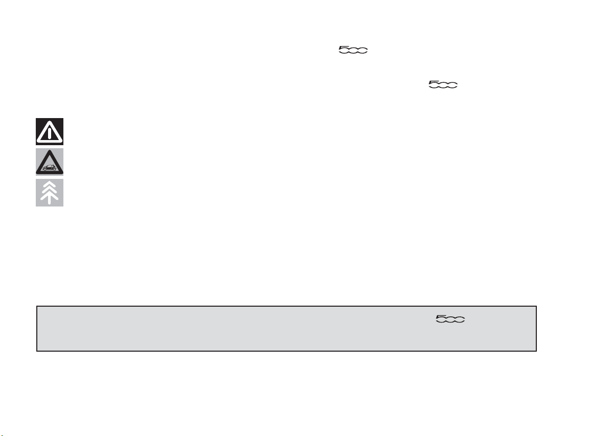
Read the warnings and indications, marked with the following symbols:
personal safety;
car safety;
environmental protection.
The enclosed Warranty Booklet lists the services that Fiat offers to its Customers:
❒ the Warranty Certificate with terms and conditions for maintaining its validity;
❒ the range of additional services available to Fiat Customers.
Enjoy reading. Happy motoring!
.
's technological
This Owner Handbook describes all the versions of the Fiat . As a
consequence, you should only consider the information which is related to the trim
level, engine and version that you have purchased.
Page 5
VERY IMPORTANT
REFUELLING
Petrol engines: only refuel with unleaded petrol
with octane rating (RON) not less than 95 in
compliance with the European Standard EN228.
The use of petrol that does not conform to
the above-mentioned specification will cause the
EOBD warning light to come on and the irregular
operation of the engine.
Diesel engines: refuel only with diesel fuel
conforming to the European specification EN590.
The use of other products or mixtures may
damage the engine beyond repair and
consequently invalidate the warranty.
STARTING THE ENGINE
Make sure that the handbrake is engaged; place
the gear lever in neutral. Fully depress the clutch
pedal, without pressing the accelerator, then
turn the ignition key to the MAR position and
wait for the
off (diesel versions); turn the ignition key to the
AVV position and release it as soon as the engine
starts.
PARKING ON FLAMMABLE MATERIAL
The catalytic converter develops high
temperatures during operation. Do not park the
car on grass, dry leaves, pine needles or other
flammable material: fire hazard.
and warning lights to switch
RESPECTING THE ENVIRONMENT
The car is fitted with a system that allows
continuous diagnosis of the components related
to emissions to ensure increased respect for
the environment.
ELECTRICAL ACCESSORIES
If, after buying the car, you decide to add
electrical accessories (with the risk of gradually
draining the battery), contact a Fiat Dealership.
They can calculate the overall electrical
requirement and check that the vehicle electric
system can support the required load.
CODE card
Keep it in a safe place, not in the car. Make sure
you have the electronic code written on the
CODE card with you at all times.
SCHEDULED SERVICING
Correct maintenance of the car is essential for
ensuring that it maintains its performance and its
safety features, its environmental friendliness
and low running costs for a long time to come.
THE OWNER MANUAL CONTAINS…
... important information, advice and warnings for
correct use, driving safety and maintenance of
your car over time. Special attention must be
paid to the symbols provided
persons) (environmental protection) (car
integrity).
(safety of
Page 6
GETTING TO KNOW YOUR CAR
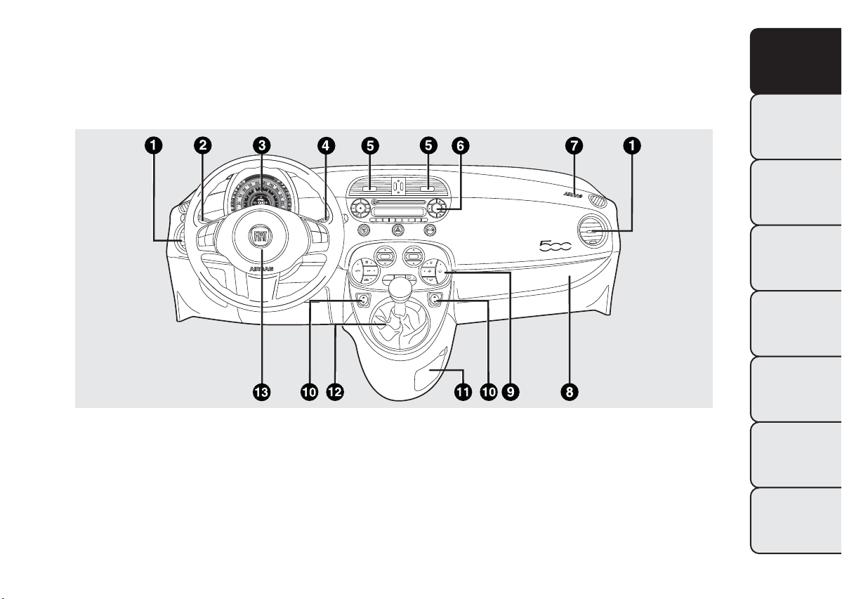
DASHBOARD
The presence and position of the controls, instruments and indicators may vary according to the different
versions.
fig. 1
1. Side air vent – 2. Left stalk: external light control – 3. Instrument panel and warning lights – 4. Right stalk: windscreen wiper
controls, rear window wiper, trip computer – 5. Centre air vents – 6. Oddments compartment/radio console – 7. Passenger
airbag – 8. Oddments compartment/hidden document holder – 9. Heating/ventilation/climate control system controls – 10.
Electric window controls – 11. Glove compartment – 12. Gear lever – 13. Driver's air bag
F0S0365
GETTING TO
KNOW YOUR CAR
SAFETY
STARTING AND
DRIVING
WARNING LIGHTS
AND MESSAGES
IN AN EMERGENCY
SERVICING AND
MAINTENANCE
TECHNICAL
SPECIFICATIONS
INDEX
3
Page 7
GETTING TO
KNOW YOUR CAR
SAFETY
STARTING AND
DRIVING
WARNING LIGHTS
AND MESSAGES
IN AN EMERGENCY
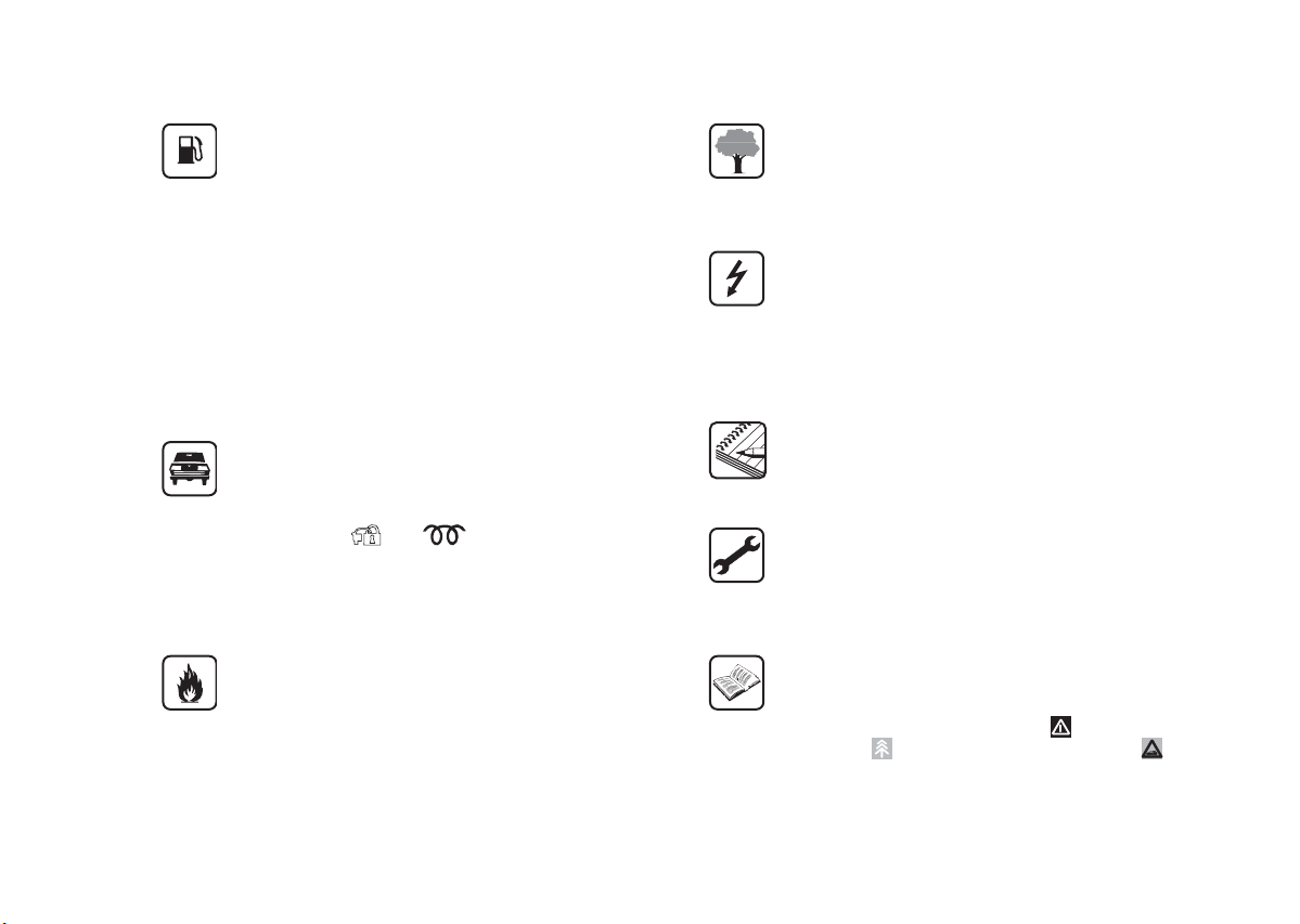
SYMBOLS
Special coloured labels have been attached near or
actually on some of the components of your car.
These labels bear symbols that remind you of the
precautions to be taken as regards that particular
component.
The inner surface of the engine bonnet includes a
label with the different symbols used.
THE FIAT CODE SYSTEM
This is an electronic engine locking system which
increases protection against attempted thefts of the
car. It is automatically activated when the ignition key
is removed.
Each time the vehicle is started by turning the
ignition key to MAR-ON, the Fiat CODE system
control unit sends a recognition code to the engine
control unit to deactivate the immobiliser.
If, during starting, the code is not correctly
recognised, a warning light
instrument panel. In this case, turn the key to STOP
and then to MAR; if it is still locked, try again with
the other keys that come with the vehicle. Contact a
Fiat Dealership if you still cannot start the engine.
IMPORTANT Each key has its own code which must
be stored by the system's electronic control unit.
Contact the Fiat Dealership to have new keys (up to
eight) stored with the code.
comes on in the
SERVICING AND
MAINTENANCE
TECHNICAL
SPECIFICATIONS
INDEX
4
Warning light
If the warning light
the system is running a self-diagnosis (for example
for a voltage drop). Should the fault persist, contact a
Fiat Dealership.
switching on while driving
switches on, this means that
Page 8
THE KEYS
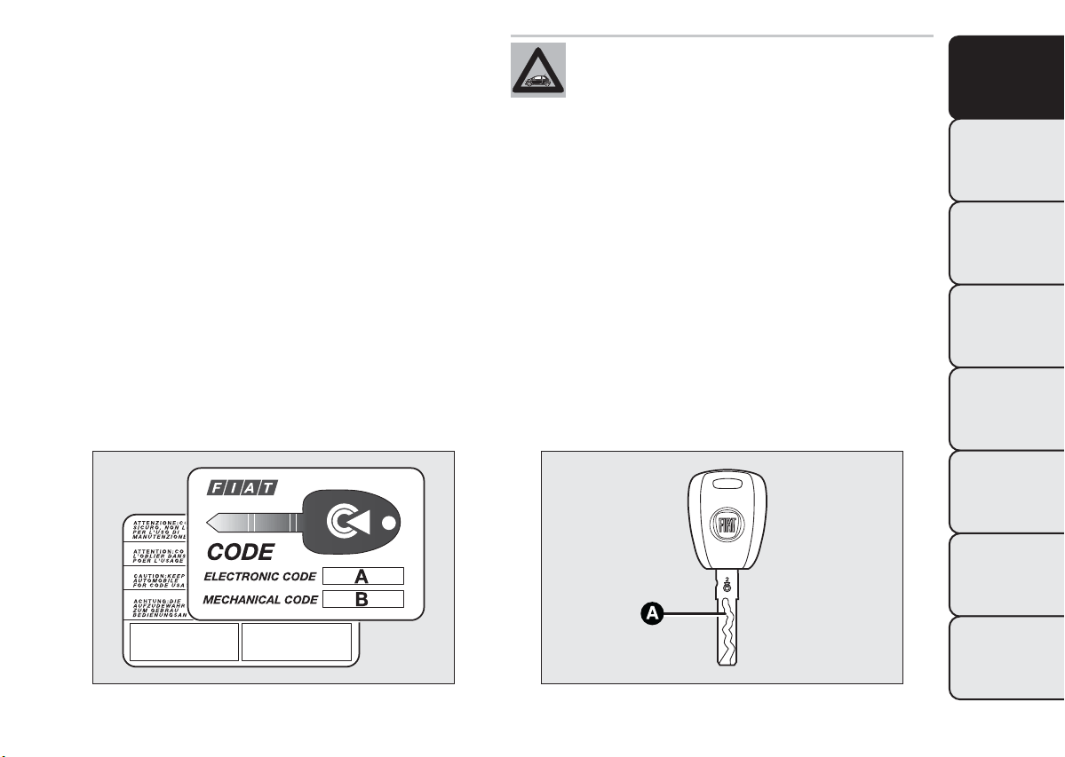
CODE CARD
(for versions/markets, where provided)
The car is delivered with two copies of the ignition
key and with the CODE card which bears the
following:
A fig. 2 the electronic code;
B fig. 2 the mechanical key code to be given to the
Fiat Dealership when ordering duplicate keys.
You should have the electronic code A with you at all
times.
IMPORTANT All the keys and the CODE card must
be handed over to the new owner when selling
the car.
The electronic components inside the key
may be damaged if the key is subjected
to strong shocks. In order to ensure
complete efficiency of the electronic devices
inside the keys, they should never be exposed to
direct sunlight.
KEY WITHOUT REMOTE CONTROL
The metal insert A fig. 3 operates:
❒ the ignition switch;
❒ the door locks and the tailgate (for versions/
markets where provided);
❒ the locking/unlocking of the fuel cap.
GETTING TO
KNOW YOUR CAR
SAFETY
STARTING AND
DRIVING
WARNING LIGHTS
AND MESSAGES
IN AN EMERGENCY
SERVICING AND
MAINTENANCE
fig. 2
F0S0002
fig. 3
TECHNICAL
SPECIFICATIONS
INDEX
F0S0003
5
Page 9
GETTING TO
KNOW YOUR CAR
SAFETY
STARTING AND
DRIVING
WARNING LIGHTS
AND MESSAGES
IN AN EMERGENCY
SERVICING AND
MAINTENANCE
TECHNICAL
SPECIFICATIONS
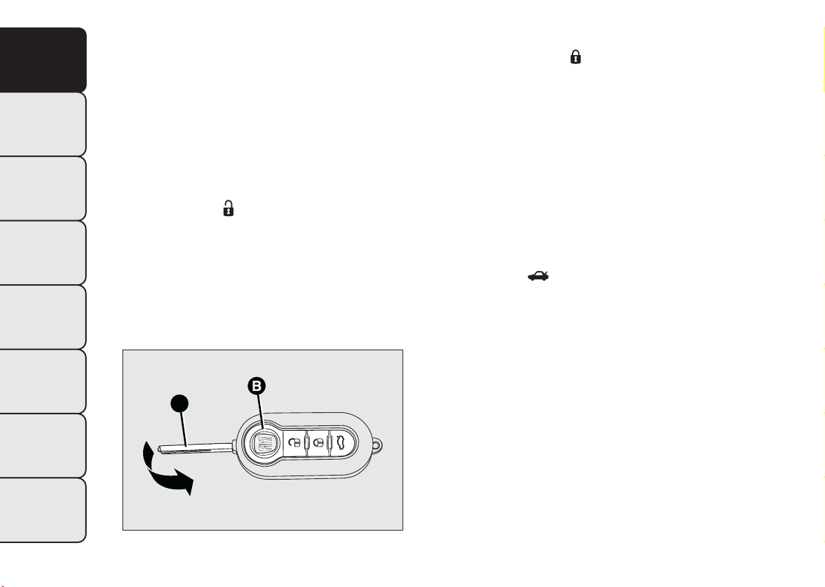
KEY WITH REMOTE CONTROL
(for versions/markets, where provided)
The metal insert A fig. 4 operates:
❒ the ignition switch;
❒ the door locks;
❒ the locking/unlocking of the fuel cap.
Press button B fig. 4 to open/close the metal insert.
Unlocking the doors and the tailgate
Briefly press button
: for unlocking of doors and
tailgate, timed switching-on of internal lights and
double flashing of direction indicators (for
versions/markets where provided).
The doors are unlocked automatically if the fuel
cut-off system intervenes.
A
Locking the doors and the tailgate
Briefly press button
: for remote locking of doors
and tailgate, switching-off of the internal ceiling lights
and single flashing of direction indicators (*).
If one or more doors are open, the doors will not be
locked. This is indicated by a rapid flashing of the
direction indicators (*). If the luggage compartment
is open, the doors will, however, be locked. When
a speed of over 20 km/h is reached, the doors will be
automatically locked if this specific function was set
(*).
(*) For versions/markets, where provided
Opening the tailgate by the remote control
Press button
to release (open) the tailgate
remotely.
The tailgate opening is indicated by double flashing of
direction indicators.
REQUEST FOR ADDITIONAL REMOTE
CONTROLS
The system can recognise up to 8 keys with
incorporated remote control. Should a new key with
remote control be necessary, contact a Fiat
Dealership, taking with you the CODE card, a
personal identity document and the car’s ownership
documents.
INDEX
6
fig. 4
F0S0004
Page 10
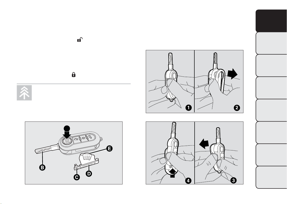
REPLACING REMOTE CONTROL BATTERY
To replace the battery, proceed as follows:
❒ press button A fig. 5 and open the metal insert B
fig. 5;
❒ turn the screw C fig. 5 to
using a fine bit
screwdriver;
❒ take out the battery case D fig. 5 and replace the
battery E fig. 5 making sure that polarities are
correct;
❒ refit the battery case D inside the key and lock it
turning the screw C to
.
REPLACINGTHE REMOTE CONTROL
COVER
Proceed as shown in the figure fig.6efig.7to
replace the remove control cover.
GETTING TO
KNOW YOUR CAR
SAFETY
STARTING AND
DRIVING
Used batteries should be disposed of, as
specified by law, in the special containers,
otherwise take them to a Fiat Dealership,
which will deal with their disposal.
A
fig. 5
F0S0005
fig. 6
fig. 7
WARNING LIGHTS
AND MESSAGES
IN AN EMERGENCY
F0S0352
SERVICING AND
MAINTENANCE
TECHNICAL
SPECIFICATIONS
INDEX
F0S0353
7
Page 11
GETTING TO
KNOW YOUR CAR
SAFETY
STARTING AND
DRIVING
WARNING LIGHTS
AND MESSAGES
IN AN EMERGENCY
SERVICING AND
MAINTENANCE
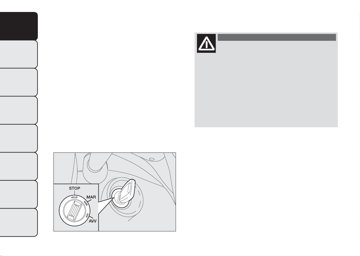
IGNITION DEVICE
The key can be turned to 3 different positions fig. 8:
❒ STOP: engine off, key can be removed, steering
column locked. Some electrical devices (e.g. sound
system, central door locking system, etc.) can
operate;
❒ MAR: driving position. All electrical devices are
enabled;
❒ AVV: engine start-up.
The ignition switch is fitted with a safety system that
requires the ignition key to be turned back to STOP
if the engine does not start, before the starting
operation can be repeated.
STEERING LOCK
Engagement: when the key is in position STOP,
remove the key and turn the steering wheel until it is
locked.
Disengagement: move the steering wheel slightly
as you turn the ignition key to MAR.
WARNING
Never remove the key while the car is
moving.The steering wheel would
automatically lock as soon as you try to turn it.
This also applies to when the car is towed. It is
absolutely forbidden to carry out any
after-market operation involving steering
system or steering column modifications (e.g.:
installation of anti-theft device) that could
badly affect performance and safety,
invalidate the warranty and also result in
non-compliance of the car with type-approval
requirements.
TECHNICAL
SPECIFICATIONS
INDEX
8
fig. 8
F0S0006
Page 12
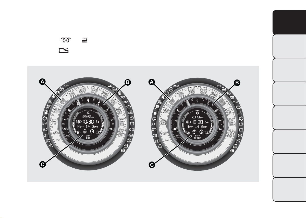
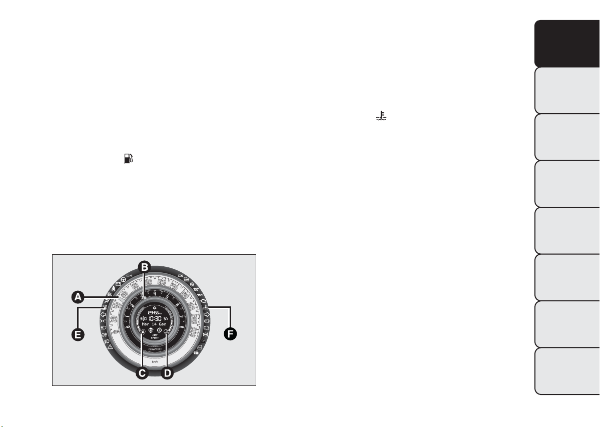
CONTROL PANEL AND
INSTRUMENTS
Instrument background colour and type may vary according to the version.
GETTING TO
KNOW YOUR CAR
The warning lights
The warning light
and are only present on Diesel versions.
is available only on versions with Dualogic gearbox (see “Dualogic” supplement).
Panel version with light background
fig. 9
A. Speedometer (speed indicator) B. Rev counter C. Multifunction display with digital fuel level indicator and digital
indicator of engine coolant temperature.
F0S0361
SAFETY
STARTING AND
DRIVING
WARNING LIGHTS
AND MESSAGES
IN AN EMERGENCY
SERVICING AND
MAINTENANCE
TECHNICAL
SPECIFICATIONS
INDEX
9
Page 13
GETTING TO
KNOW YOUR CAR
SAFETY
STARTING AND
DRIVING
WARNING LIGHTS
AND MESSAGES
IN AN EMERGENCY
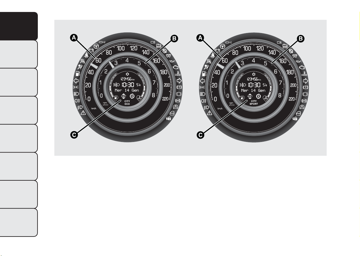
Panel version with dark background
SERVICING AND
MAINTENANCE
A. Speedometer (speed indicator) B. Rev counter C. Multifunction display with digital fuel level indicator and digital
indicator of engine coolant temperature.
TECHNICAL
SPECIFICATIONS
INDEX
10
fig. 10
F0S0362
Page 14
SPEEDOMETER (SPEED INDICATOR)
The indicator A fig. 11 shows the car speed
(speedometer).
REV COUNTER
The indicator B fig. 11 shows the engine rpm.
DIGITAL FUEL LEVEL INDICATOR
The digital indicator C fig. 11 shows the amount of
fuel in the tank.
The warning light E
fig. 11 switches on to indicate
that approximately 5 litres of fuel are left in the tank.
Do not travel with the fuel tank almost empty: the
gaps in fuel delivery could damage the catalyst.
ENGINE COOLANT TEMPERATURE
INDICATOR
The digital indicator D fig. 11 shows the temperature
of the engine coolant fluid and starts working when
the fluid temperature exceeds approx. 50°C.
The first segment is always on to show the correct
operation of the system.
The warning light F
fig. 11 (with a message on the
multifunction display) indicates that the coolant
temperature is too high; in this case, stop the engine
and contact the Fiat Dealership.
GETTING TO
KNOW YOUR CAR
SAFETY
STARTING AND
DRIVING
WARNING LIGHTS
AND MESSAGES
IN AN EMERGENCY
SERVICING AND
MAINTENANCE
fig. 11
TECHNICAL
SPECIFICATIONS
INDEX
F0S0284
11
Page 15
GETTING TO
KNOW YOUR CAR
SAFETY
STARTING AND
DRIVING
WARNING LIGHTS
AND MESSAGES
IN AN EMERGENCY
SERVICING AND
MAINTENANCE
TECHNICAL
SPECIFICATIONS
MULTIFUNCTION DISPLAY
The car may be equipped with a multifunction display
that, according to previous settings, will show useful
driving information.
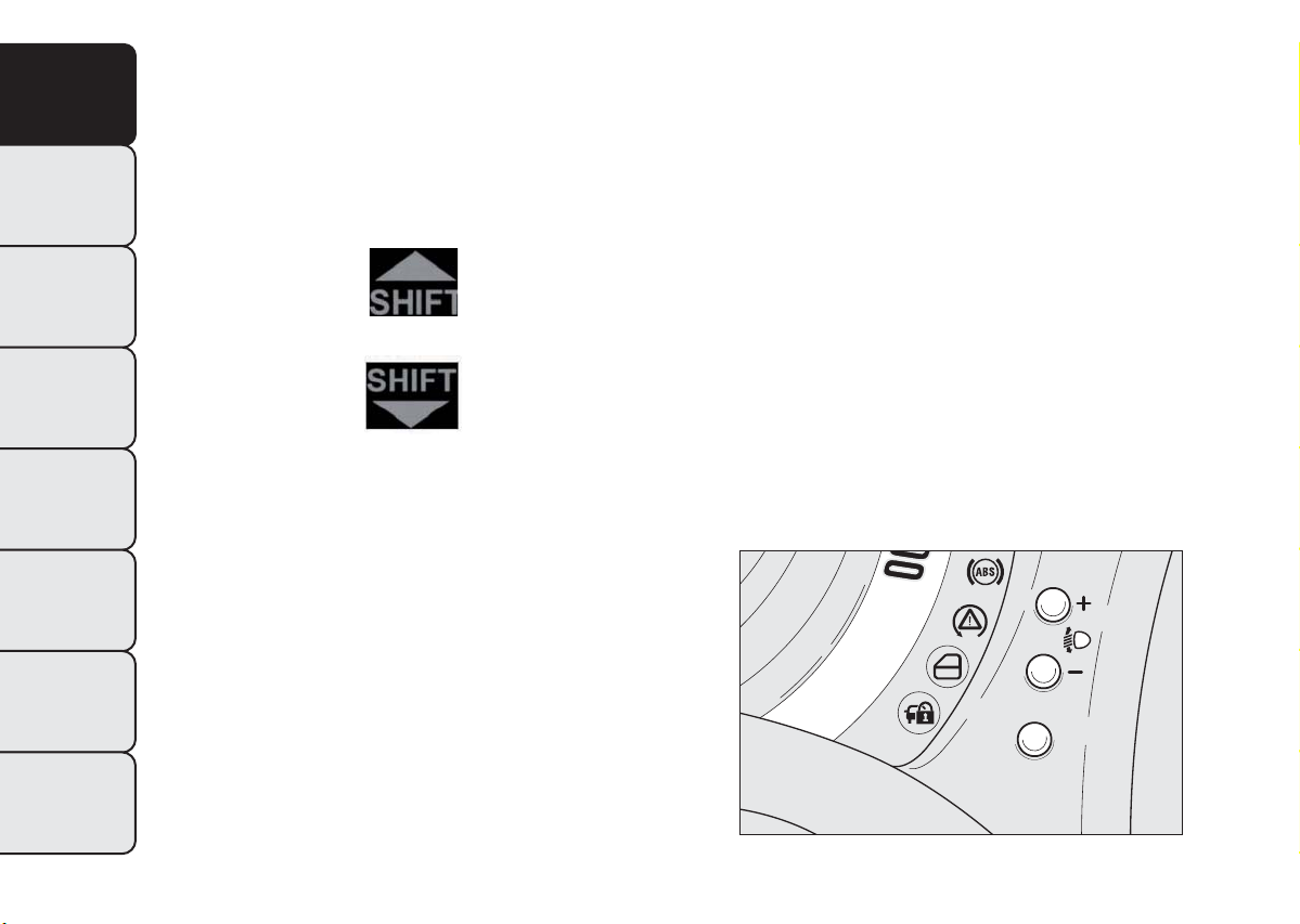
GEAR SHIFT INDICATION
(for versions/markets, where provided)
Shift up
Shift down
On vehicles with a manual gearbox, the gear shift
indicator suggests gear changes to the driver (SHIFT
UP or SHIFT DOWN) via a special display on the
control panel. This suggestion to change gear is
designed to improve consumption and ensure the
best driving style.
Note The indication in the instrument panel remains
on until the driver shifts gear or the driving
conditions go back to a situation where gearshifting
is not required to improve consumption.
CONTROL BUTTONS
To scroll through the screen and the related
+
options upwards or to increase the value displayed
fig. 12.
MENU ESC
Press briefly to access the menu and/or
go to next screen or to confirm the
required menu option. Hold down to go
back to the standard screen.
To scroll through the screen and the options
–
downwards or to decrease the value displayed.
Note Buttons + and – activate different functions
according to the following situations:
❒ within the menu, they allow you to scroll up and
down through the options;
❒ during settings operations, they increase or
decrease values.
12
INDEX
fig. 12
M E N U
E S C
F0S0089
Page 16
Note When one of the front doors is opened, the
display is activated showing the time and km/mileage
(for markets/versions, where provided) for a few
seconds.
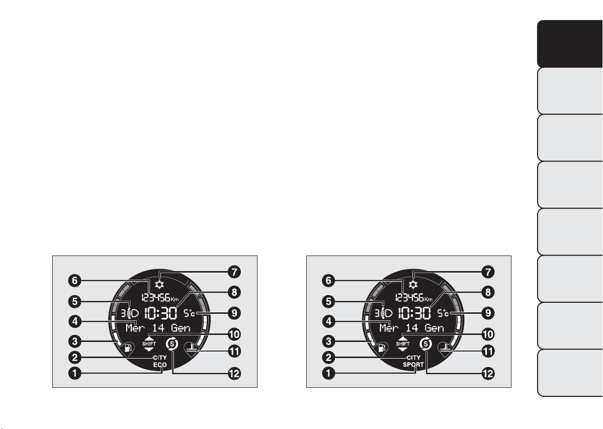
MULTIFUNCTION DISPLAY “STANDARD”
SCREEN
The standard screen fig. 13-fig. 14 can show the
following information:
SPORT driving mode indication (versions 1.4 16V)
1
ECO driving mode indication (0.9 TwinAir 85
HP versions)
Dualdrive electric steering engagement
2
Digital fuel level indicator
3
Date
4
Headlamp alignment position (only with dipped
5
headlamps on)
Odometer (display of distance travelled in
6
kilometres/miles)
Possible ice on the road indication
7
Time
8
External temperature indicator
9
Gear Shift Indication
10
Digital engine coolant temperature gauge
11
Start&Stop (for versions/markets, where
12
provided)
SETUP MENU
The menu comprises a series of functions arranged in
a cycle which can be selected through buttons +
and – to access the different select operations and
settings (setup) given in the following paragraphs.
A submenu is provided for some items (Clock and
Unit of measurement).
GETTING TO
KNOW YOUR CAR
SAFETY
STARTING AND
DRIVING
WARNING LIGHTS
AND MESSAGES
IN AN EMERGENCY
SERVICING AND
MAINTENANCE
fig. 13
F0S0364
fig. 14
TECHNICAL
SPECIFICATIONS
INDEX
F0S0363
13
Page 17

GETTING TO
KNOW YOUR CAR
SAFETY
STARTING AND
DRIVING
WARNING LIGHTS
AND MESSAGES
IN AN EMERGENCY
SERVICING AND
MAINTENANCE
TECHNICAL
SPECIFICATIONS
The setup menu can be activated by pressing the
MENU ESC button briefly. Single presses on buttons
+ or – will scroll through the setup menu options.
Operating modes are different according to the
characteristics of the option selected.
The menu includes the following functions:
❒ LIGHTING
❒ SPEED BEEP
❒ TRIP B DATA
❒ SET TIME
❒ SET DATE
❒ SEE RADIO
❒ AUTOCLOSE
❒ MEASUREMENT UNIT
❒ LANGUAGE
❒ BUZZER VOLUME
❒ BUTTON VOLUME
❒ BELT BUZZER
❒ SERVICE
❒ PASSENGER AIRBAG
❒ DAYTIME RUNNING LIGHTS
❒ EXIT MENU
Selecting an option from the main menu wi thout a
submenu:
❒ briefly press the MENU ESC button to select the
main menu option you wish to modify;
❒ press buttons + or – (with single presses) to select
the new setting;
❒ a short press on button MENU ESC will store the
setting and then return to the same main menu
option that was first selected.
Selecting an option from the main menu wi th a
submenu:
❒ a short press on MENU ESC button will display
the first submenu option;
❒ press buttons + or – (with single presses) to scroll
through all the submenu options;
❒ a short press on MENU ESC button will select the
displayed submenu option and enter the associated
setting menu;
❒ press buttons + or – (with single presses) to select
the new setting for this submenu option;
❒ a short press on button MENU ESC will store the
setting and then return to the same submenu
option that was first selected.
14
INDEX
Page 18

MENU FUNCTIONS
Passenger compartment light adjustment
The instrument panel with reconfigurable
multifunction display is provided with a light sensor
capable of detecting environmental light conditions
and adjusting the brightness of the instruments
accordingly.
The brightness of the instrument panel may
therefore change while travelling following an event
causing a switch from “day” to “night” conditions (or
vice versa) in the passenger compartment (e.g. in a
tunnel, on avenues in shadows, under flyovers, etc.).
This function is available, with the dipped headlamps
on and in night-time conditions, to adjust the
brightness of the instrument panel, buttons, sound
system display and automatic climate control display.
For versions/markets, where provided, during the
daytime, and with the dipped headlamps on, the
instrument panel, buttons and sound system and
automatic climate control displays are set to
maximum brightness.
To adjust the light intensity, proceed as follows:
❒ press the MENU ESC button briefly to make the
display flash the previously stored level;
❒ press button + or – to adjust the brightness level;
❒ press the MENU ESC button briefly to return
to the menu screen or give the button a long press
to return to the standard screen without storing.
Speed Beep (Speed limit)
This function is used to set the car speed limit (km/h
or mph); the driver is immediately alerted when
this limit is exceeded (see section “Warning lights
and messages”).
To set the desired speed limit, proceed as follows:
❒ briefly press the MENU ESC button to make
the display show the words (Speed Beep);
❒ press button + or – to select speed limit activation
(On) or deactivation (Off);
❒ if the function is on, press + or – to select the
required speed limit and then press MENU ESC to
confirm.
Note Setting is possible between 30 and 200 km/h,
or 20 and 125 mph, according to the previously
set unit. See the "Measurement unit adjustment
(Measurement unit)" paragraph described below. The
setting will increase/decrease by five units each time
button +/- is pressed. Hold down the button +/-
to increase/decrease the setting rapidly. Complete
the setting by briefly pressing the button when
you approach the required value.
❒ press the MENU ESC button briefly to return to
the menu screen or give the button a long press
to return to the standard screen without storing.
To cancel the setting, proceed as follows:
❒ press the MENU ESC button briefly to make the
display flash (On);
GETTING TO
KNOW YOUR CAR
SAFETY
STARTING AND
DRIVING
WARNING LIGHTS
AND MESSAGES
IN AN EMERGENCY
SERVICING AND
MAINTENANCE
TECHNICAL
SPECIFICATIONS
INDEX
15
Page 19

GETTING TO
KNOW YOUR CAR
SAFETY
STARTING AND
DRIVING
WARNING LIGHTS
AND MESSAGES
IN AN EMERGENCY
SERVICING AND
MAINTENANCE
TECHNICAL
SPECIFICATIONS
INDEX
❒ press button – : (Off) will flash on the display;
❒ press the MENU ESC button briefly to return to
the menu screen or give the button a long press
to return to the standard screen without storing.
Trip B data (Activating Trip B)
With this function is possible to turn the Trip B
display (trip meter) on and off.
For further information see “Trip computer”.
Proceed as follows to switch the function on and off:
❒ press the MENU ESC button briefly, the display
will flash On or Off depending on the previous
setting;
❒ press button + or – to set;
❒ press the MENU ESC button briefly to return to
the menu screen or give the button a long press
to return to the standard screen without storing.
Time adjustment (Clock adjustment)
This function enables to set the clock through two
sub-menus: “Time” and “Format”.
To carry out the adjustment, proceed as follows:
❒ briefly press MENU ESC: the display will show the
two submenus “Time” and “Mode”;
❒ press the button + or – to switch between the
two submenus;
❒ once the submenu to be modified has been
selected, briefly press the MENU ESC button;
❒ when you select “Time”, pressing MENU ESC
briefly makes the "hours" flash on the display;
❒ press + or – to set the value;
❒ briefly press MENU ESC: the “minutes” will flash
on the display;
❒ press + or – to set the value.
Note The setting will increase or decrease by one
unit each time the button + or – is pressed. Hold
down the button to increase/decrease the setting
rapidly and automatically. Complete the setting
by briefly pressing the button when you approach the
required value.
❒ when you select “Mode”, pressing MENU ESC
makes the mode flash on the display;
❒ press button + or – to select “24h” or “12h mode.
When you have made the required adjustments,
press MENU ESC to go back to the submenu
screen or hold the button down to go back to the
main menu screen without saving.
❒ again, give the MENU ESC button a long press to
return to the standard screen or to the main
menu according to the position in the menu.
Set date (Setting the date)
Using this function it is possible to update the date
(day - month - year).
Proceed as follows to update:
❒ briefly press MENU ESC: “year” will flash on the
display;
16
Page 20

❒ press + or – to set the value;
❒ briefly press MENU ESC: “month” will flash on the
display;
❒ press + or – to set the value;
❒ briefly press MENU ESC: “day” will flash on the
display;
❒ press + or – to set the value;
Note The setting will increase or decrease by one
unit each time the button + or – is pressed. Hold
down the button to increase/decrease the setting
rapidly and automatically. Complete the setting
by briefly pressing the button when you approach the
required value.
❒ press the MENU ESC button briefly to return to
the menu screen or give the button a long press
to return to the standard screen without storing.
See radio (audio information display)
With this function the display shows information
about the sound system.
❒ Radio: selected radio station frequency or RDS
message, automatic tuning activation or
AutoSTore;
❒ Audio CD, MP3 CDs: track number.
To show the sound system information on the
display (On) or clear it (Off ), proceed as follows:
❒ briefly press the MENU ESC button, making the
display flash On or Off according to the previously
set level;
❒ press button + or – to set;
❒ press the MENU ESC button briefly to return to
the menu screen or give the button a long press
to return to the standard screen without storing.
Autoclose (automatic central locking with the
car in motion - where provided)
When activated (On), this function locks the doors
automatically when the vehicle speed exceeds 20
km/h.
Proceed as follows to activate or deactivate this
function:
❒ press the MENU ESC button briefly to display a
submenu;
❒ press the MENU ESC button briefly to make the
display flash On or Off according to the previously
stored level;
❒ press button + or – to set;
❒ press the MENU ESC button briefly to return to
the submenu screen or give the button a long
press to return to the main menu screen without
storing;
❒ again, give the MENU ESC button a long press to
return to the standard screen or to the main
menu according to the position in the menu.
GETTING TO
KNOW YOUR CAR
SAFETY
STARTING AND
DRIVING
WARNING LIGHTS
AND MESSAGES
IN AN EMERGENCY
SERVICING AND
MAINTENANCE
TECHNICAL
SPECIFICATIONS
INDEX
17
Page 21

GETTING TO
KNOW YOUR CAR
SAFETY
STARTING AND
DRIVING
WARNING LIGHTS
AND MESSAGES
IN AN EMERGENCY
SERVICING AND
MAINTENANCE
TECHNICAL
SPECIFICATIONS
INDEX
Unit of measurement (Setting the unit of
measurement)
With this function it is possible to set the units
through three submenus: "Distances",
"Consumption" and "Temperature".
To set the required unit proceed as follows:
❒ briefly press the MENU ESC button, displaying
three submenus;
❒ press button + or – to browse the three
sub-menus;
❒ once the submenu to be modified has been
selected, briefly press the MENU ESC button;
❒ when you select “Distances”, briefly pressing
MENU ESC makes the display show "km" or "mi"
depending on the previous setting;
❒ press button + or – to set;
❒ when you select “Consumption”, briefly pressing
MENU ESC makes km/l, l/100km or mpg appear
on the display depending on the previous setting;
If the set distance unit is "km", the fuel consumption
unit will be displayed in km/l or l/100 km.
If the set distance unit is “mi” the fuel consumption
unit will be displayed in “mpg”.
❒ press button + or – to set;
❒ when you select “Temperature”, pressing MENU
ESC makes °C or °F appear on the display
depending on the previous setting;
❒ press button + or – to set;
When you have made the required adjustments,
briefly press button MENU ESC to go back to the
submenu screen or hold the button down to go back
to the main menu screen without saving.
❒ again, give the MENU ESC button a long press to
return to the standard screen or to the main
menu according to the position in the menu.
Language (Language selection)
Display messages can be shown in different
languages: Italian, English, German, Portuguese,
Spanish, French, Dutch and Polish.
To set the desired language, proceed as follows:
❒ briefly press MENU ESC: the previously set
“language” will flash on the display;
❒ press button + or – to set;
❒ press the MENU ESC button briefly to return to
the menu screen or give the button a long press
to return to the standard screen without storing.
Warnings volume (Adjusting the alert/warning
acoustic signal volume)
With this function the volume of the buzzer which
accompanies the display of any failure/warning can be
adjusted according to 8 levels.
To set the desired volume, proceed as follows:
❒ briefly press MENU ESC: the previously set
volume level will flash on the display;
18
Page 22

❒ press + or – to set the value;
❒ press the MENU ESC button briefly to return to
the menu screen or give the button a long press
to return to the standard screen without storing.
Button volume (Adjusting the button volume)
This function may be used to adjust (over 8 levels)
the volume of the noise made when the MENU ESC,
+ and – buttons are pressed.
To set the desired volume, proceed as follows:
❒ briefly press MENU ESC: the previously set
volume level will flash on the display;
❒ press + or – to set the value;
❒ press the MENU ESC button briefly to return to
the menu screen or give the button a long press
to return to the standard screen without storing.
Belt buzzer (Buzzer activation for S.B.R.
indication)
This function can only be displayed after a Fiat
Dealership has deactivated the SBR system (see “SBR
system” in the “Safety” section).
Service (Scheduled servicing)
Using this function you can display information about
the mileage intervals for car servicing.
To consult this display, proceed as follows:
❒ briefly press the MENU ESC button, which makes
the display show the service interval in km or mi
according to the previous setting (see "Distance
units of measurement" paragraph);
❒ press the MENU ESC button briefly to return to
the menu screen or give the button a long press
to return to the standard screen.
Note The "Scheduled Servicing Plan" requires the
vehicle to be serviced every 30,000 km (or 18,000
miles). This is automatically displayed, when the
ignition key is turned to MAR, from 2,000 km (or the
equivalent in miles) and reappears every 200 km (or
the equivalent in miles). Below 200 km servicing
indications are more frequent. The display will be in
kilometres or miles depending on the measurement
unit settings. When the next scheduled service is
approaching and the key is turned to MAR, the word
Service will appear on the display, followed by the
number of kilometres or miles left. Go to a Fiat
Dealership, where the "Scheduled Servicing Plan"
operations will be performed and the message will
be reset.
Passenger air bag (Activation/deactivation of
passenger-side front air bag and side bag to
protect chest/pelvis area)
(*) For versions/markets where provided
This function is used to activate/deactivate the front
passenger's airbag.
GETTING TO
KNOW YOUR CAR
SAFETY
STARTING AND
DRIVING
WARNING LIGHTS
AND MESSAGES
IN AN EMERGENCY
SERVICING AND
MAINTENANCE
TECHNICAL
SPECIFICATIONS
INDEX
19
Page 23

GETTING TO
KNOW YOUR CAR
SAFETY
STARTING AND
DRIVING
WARNING LIGHTS
AND MESSAGES
IN AN EMERGENCY
SERVICING AND
MAINTENANCE
TECHNICAL
SPECIFICATIONS
Proceed as follows:
❒ press MENU ESC and, after the message Bag pass:
Off (to deactivate) or Bag pass: On (to activate) is
displayed by pressing buttons + or – , press MENU
ESC again;
❒ the confirmation message will appear on the
display;
❒ press buttons + or – to select (Yes) (confirming
activation/deactivation) or (No) (to abort);
❒ press the MENU ESC button briefly, a message
confirming the selection will be displayed and
you will return to the menu screen or pressing the
button for longer you will return to the standard
screen without storing.
Daytime Running Lights (DRL)
With this function is possible to turn the day lights
on and off.
Proceed as follows to activate or deactivate this
function:
❒ press the MENU ESC button briefly to display a
submenu;
❒ press the MENU ESC button briefly to make the
display flash On or Off according to the previously
stored level;
❒ press button + or – to set;
❒ press the MENU ESC button briefly to return to
the submenu screen or give the button a long
press to return to the main menu screen without
storing;
❒ again, give the MENU ESC button a long press to
return to the standard screen or to the main
menu according to the position in the menu.
Exit menu
This function closes the cycle of settings listed in the
menu screen.
Briefly press MENU ESC to go back to the standard
screen without saving.
Press – to return to the first menu option (Speed
Beep).
20
INDEX
Page 24

TRIP COMPUTER
General information
The Trip computer is used to display information on
car operation when the key is turned to MAR.
This function is composed of separate trips, called
“Trip A” and “Trip B” which can monitor the entire
mission (journey) in a reciprocally independent
manner.
Both functions can be reset (reset means start of a
new journey).
“Trip A” is used to display the figures relating to:
❒ Range
❒ Distance travelled
❒ Average consumption
❒ Current consumption
❒ Average speed
❒ Trip time (driving time).
“Trip B” may be used to display the figures relating
to:
❒ Distance travelled B
❒ Average consumption B
❒ Average speed B
❒ Trip time B (driving time).
Note The “Trip B” function may be disabled (see
“Activating Trip B”). “Range” and “Instant
consumption" parameters cannot be reset.
Values displayed
Range
This value shows the distance that the car can still
cover before needing fuel, assuming that driving style
is unvaried. “----”will appear on the display in
the following cases:
❒ range value lower than 50 km (or 30 mi)
❒ car parked with engine running for a long period.
IMPORTANT The range can be affected by several
factors: driving style (see “Driving style” paragraph in
the “Starting and driving” chapter), type of route
(motorway, towns and cities, mountain roads, etc.),
conditions of use (load, tyre pressures, etc.). Trip
planning must therefore take the above into account.
Distance travelled
This value shows the distance covered from the start
of the new journey.
Average consumption
This value shows the approximate average fuel
consumption from the start of the new journey.
Current consumption
This value shows the fuel consumption. The value is
constantly updated. The display will show “----”
if the car is parked with the engine running.
GETTING TO
KNOW YOUR CAR
SAFETY
STARTING AND
DRIVING
WARNING LIGHTS
AND MESSAGES
IN AN EMERGENCY
SERVICING AND
MAINTENANCE
TECHNICAL
SPECIFICATIONS
INDEX
21
Page 25
GETTING TO
KNOW YOUR CAR
SAFETY
STARTING AND
DRIVING
WARNING LIGHTS
AND MESSAGES
IN AN EMERGENCY
SERVICING AND
MAINTENANCE
Average speed
This value shows the car's average speed based on
the overall time elapsed since the start of the new
journey.
Journey time
Time elapsed since the start of the new journey.
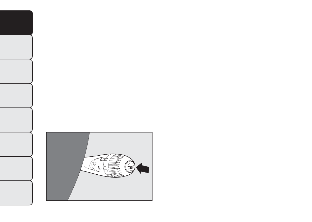
TRIP control button
The TRIP button is located on the right hand stalk
fig. 15. With the ignition key turned to MAR-ON,
this button allows you to view the previously
described parameters and also zero them to begin a
new mission:
❒ brief press to access the various parameter
displays;
❒ long press to reset and then start a new mission.
New mission
It begins after a reset:
❒ “manual” resetting by the user, by pressing the
relevant button;
❒ “automatic” resetting, when the “Trip distance”
reaches 9999.9 km or when the “Travel time”
reaches 99:59 (99 hours and 59 minutes);
❒ disconnection/reconnection of the battery.
IMPORTANT The reset operation when “Trip A” or
“Trip B” details are being displayed resets the
information associated with the function displayed.
Start of journey procedure
With the ignition key in the MAR-ON position, reset
by pressing the TRIP button and keeping it pressed
for more than 2 seconds.
Exit Trip
You can automatically exit the TRIP function once all
the values have been displayed or by holding the
MENU ESC button down for more than 1 second.
TECHNICAL
SPECIFICATIONS
INDEX
22
fig. 15
F0S0090
Page 26

FRONT SEATS
WARNING
All adjustments must be made with the
car stationary.
LENGTHWISE DIRECTION ADJUSTMENT
Lift the lever A fig. 16 and push the seat forwards or
backwards: in the driving position your arms should
rest on the rim of the steering wheel.
WARNING
Once you have released the adjustment
lever, always check that the seat is
locked on the guides by trying to move it back
and forth. Failure to lock the seat in place could
result in the seat moving suddenly and the
driver losing control of the car.
ADJUSTING BACKREST INCLINATION
Turn knob B fig. 17.
GETTING TO
KNOW YOUR CAR
SAFETY
STARTING AND
DRIVING
WARNING LIGHTS
AND MESSAGES
IN AN EMERGENCY
SERVICING AND
MAINTENANCE
fig. 16
F0S0013
fig. 17
TECHNICAL
SPECIFICATIONS
INDEX
F0S0014
23
Page 27
GETTING TO
KNOW YOUR CAR
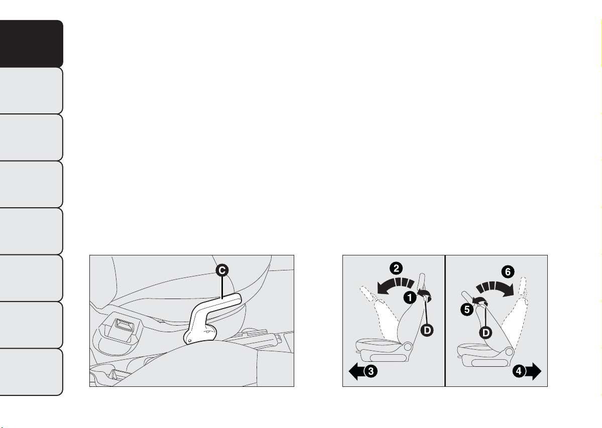
HEIGHT ADJUSTMENT
(for versions/markets, where provided)
Operate lever C fig. 18 to lift or lower the rear part
of the cushion to achieve the most comfortable
driving position.
IMPORTANT Using lever D fig. 19 before locking the
seat in its original position will cause the initial seat
position to be lost. In this case the position of the
seat must be restored through lengthwise adjustment
A fig. 16.
SAFETY
BACKREST FOLDING
To fold the backrest over, adjust lever D fig. 19
(movement 1) and push the backrest forwards until it
STARTING AND
DRIVING
locks (movement 2); release lever D and, pushing
the backrest, slide the seat forwards (movement 3).
DRIVER AND PASSENGER SIDES WITH
WARNING LIGHTS
AND MESSAGES
POSITION MEMORY
(for versions/markets, where provided)
To restore the seat to its original position, slide the
seat backwards pushing the backrest until the seat
locks (movement 4), adjust lever D fig. 19
IN AN EMERGENCY
(movement 5) and raise the backrest (movement 6)
until the locking can be heard.
SERVICING AND
MAINTENANCE
TECHNICAL
SPECIFICATIONS
INDEX
PASSENGER SIDE WITHOUT POSITION
MEMORY
To restore the seat to its original position, slide the
seat backwards pushing the backrest until the desired
position is reached (movement 4), adjust lever D
fig. 19 (movement 5) and raise the backrest
(movement 6) until the locking can be heard.
24
fig. 18
F0S0015
fig. 19
F0S0154
Page 28
The type of reattachment manoeuvre has been
chosen to guarantee the safety of the occupant. If an
obstacle is present (e.g. a bag) and the seat cannot
be returned to its original position, the mechanism
reattaches the seat only positioning the backrest
to ensure that the guides are always locked.
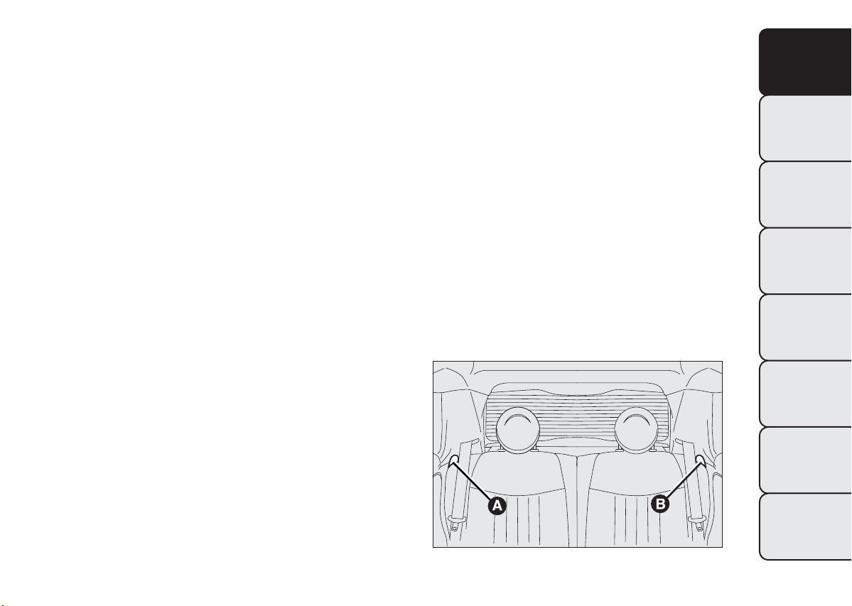
REAR SEATS
BACKREST RELEASE
For versions with joint seat, lift levers A fig. 20 and B
fig. 20 and guide the backrest onto the cushion.
For versions with split seat, lift lever A or B to
release respectively the left or right part of
the backrest and guide the backrest onto the
cushion.
GETTING TO
KNOW YOUR CAR
SAFETY
STARTING AND
DRIVING
WARNING LIGHTS
AND MESSAGES
IN AN EMERGENCY
SERVICING AND
MAINTENANCE
fig. 20
TECHNICAL
SPECIFICATIONS
INDEX
F0S0017
25
Page 29
GETTING TO
KNOW YOUR CAR
SAFETY
STARTING AND
DRIVING
WARNING LIGHTS
AND MESSAGES
IN AN EMERGENCY
SERVICING AND
MAINTENANCE
HEAD RESTRAINTS
FRONT
Head restraints are height adjustable; to adjust them
operate as follows.
Upwards adjustment: lift the head restraint until
it locks.
Downwards adjustment: press the button A
fig. 21 and lower the head restraint.
WARNING
All adjustments must be carried out only
with the vehicle stationary and engine
off. Head restraints must be adjusted so that
the head, rather than the neck, rests on them.
Only in this case can they protect your head
correctly.
WARNING
To make the best use of the head
restraint protective action, adjust the
backrest so that you are setting upright and
keep your head as close as possible to the head
restraint.
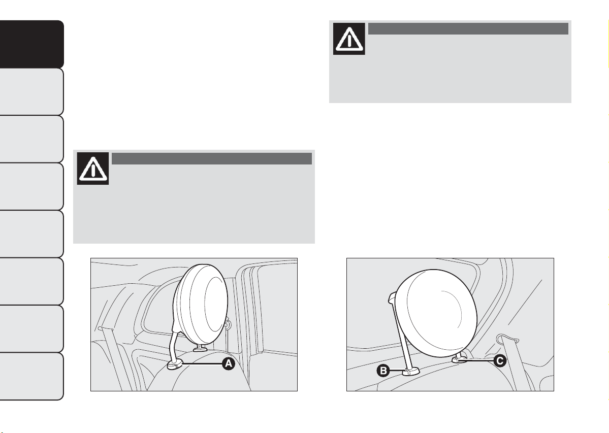
REAR
(for versions/markets, where provided)
To extract the rear head restraints press buttons B
fig. 22 and C fig. 22 at the side of the two supports
simultaneously and upwards. The rear head restraints
must be lifted out with the backrest released and
tilted toward the passenger compartment or with
the tailgate open. To bring the head restraint to the
correct position, lift it until you hear it click.
TECHNICAL
SPECIFICATIONS
INDEX
26
fig. 21
F0S0033
fig. 22
F0S0034
Page 30

To lower the head restraint press button B. The
particular head restraint shape deliberately interferes
with the passenger correctly supporting their back
on the backrest in order to force them to lift the
head restraint and use it correctly.
IMPORTANT If the rear seats are used, always set
the head restraints in the "completely raised"
position.
STEERING WHEEL ADJUSTMENT
(for versions/markets, where provided)
The steering wheel can be adjusted vertically.
To adjust, move lever A fig. 23 downwards to
position 2, then adjust the steering wheel to the
most suitable position and lock it in position by
moving lever A to position 1.
GETTING TO
KNOW YOUR CAR
SAFETY
off.
WARNING
All adjustments must be carried out only
with the vehicle stationary and engine
fig. 23
STARTING AND
DRIVING
WARNING LIGHTS
AND MESSAGES
IN AN EMERGENCY
SERVICING AND
MAINTENANCE
TECHNICAL
SPECIFICATIONS
INDEX
F0S0018
27
Page 31

GETTING TO
KNOW YOUR CAR
SAFETY
INTERIOR REAR VIEW MIRROR
The mirror is fitted with a safety device that causes
its release in the event of a violent impact with
the passenger. Lever A fig. 24 can be used to move
the mirror to two different positions: normal or
antiglare.
DOOR MIRRORS
WITH MANUAL ADJUSTMENT
The door mirror can be adjusted from outside by
exerting a slight pressure on the four sides of the
glass.
ELECTROCHROMIC INTERIOR MIRROR
(for versions/markets, where provided)
STARTING AND
DRIVING
Some versions have an electrochromic mirror with
automatic antiglare function. There is an ON/OFF
button on the lower part of the mirror for
WARNING LIGHTS
AND MESSAGES
activating/deactivating the electrochromic function.
When the function is active, a LED on the mirror
is active. When reverse gear is engaged, the mirror is
automatically set for daytime use.
IN AN EMERGENCY
SERVICING AND
MAINTENANCE
TECHNICAL
SPECIFICATIONS
INDEX
28
fig. 24
F0S0019
WITH ELECTRICAL ADJUSTMENT
Proceed as follows:
❒ select the mirror using selector B fig. 25;
❒ adjust the mirror using the joystick A fig. 25 in the
four directions.
fig. 25
F0S0020
Page 32

FOLDING THE MIRRORS
When required (for example when the mirror causes
difficulty in narrow spaces) it is possible to fold the
mirrors by moving them from position 1 fig. 26
(open), to position 2 fig. 26 (closed).
WARNING
As door mirrors are curved, they may
slightly alter the perception of distance.
When driving the mirrors should always be in
position 1.
GETTING TO
KNOW YOUR CAR
SAFETY
STARTING AND
DRIVING
WARNING LIGHTS
AND MESSAGES
IN AN EMERGENCY
SERVICING AND
MAINTENANCE
fig. 26
TECHNICAL
SPECIFICATIONS
INDEX
F0S0035
29
Page 33

GETTING TO
KNOW YOUR CAR
SAFETY
STARTING AND
DRIVING
WARNING LIGHTS
AND MESSAGES
IN AN EMERGENCY
SERVICING AND
MAINTENANCE
TEMPERATURE COMFORT
VENTS
TECHNICAL
SPECIFICATIONS
INDEX
30
fig. 27
1. Vents for defrosting or demisting the windscreen – 2. Adjustable centre vents – 3. Adjustable side vents – 4. Fixed diffusers
for side windows – 5. Lower diffusers
F0S0021
Page 34

HEATING AND VENTILATION
ADDITIONAL HEATER
(for versions/markets, where provided)
This device speeds up passenger compartment
warming when it is very cold. The additional heater
turns off automatically after reaching the required
comfort conditions.
Important
The heater only works if the outside temperature
and engine coolant temperature are low.
The heater will not activate if the battery voltage is
too low.
CONTROLS
A Air temperature knob fig. 28 (red = hot/blue =
cold)
B Fan speed knob fig. 28
IMPORTANT It is advisable to switch the air
recirculation on whilst queueing or in tunnels to
prevent the introduction of polluted air. However, it
is better not to use the function for long periods,
particularly if there are many people on board,
to prevent the windows from misting inside.
D Air distribution knob fig. 28
toward the body
and the side windows
toward the body, the side windows and the feet
toward the feet only
toward the feet and the windshield
toward the windscreen only.
E Heated rear window activation/ deactivation
button fig. 28. The LED on the button comes on
to indicate activation.
In order to maintain battery efficiency, the function is
automatically deactivated after about 20 minutes.
GETTING TO
KNOW YOUR CAR
SAFETY
STARTING AND
DRIVING
WARNING LIGHTS
AND MESSAGES
IN AN EMERGENCY
Note To stop the air flow from the vents turn the
knob to 0.
C Air recirculation knob fig. 28
– internal air
recirculation
– air intake from outside
fig. 28
SERVICING AND
MAINTENANCE
TECHNICAL
SPECIFICATIONS
INDEX
F0S0376
31
Page 35

GETTING TO
KNOW YOUR CAR
SAFETY
STARTING AND
DRIVING
WARNING LIGHTS
AND MESSAGES
IN AN EMERGENCY
SERVICING AND
MAINTENANCE
Fast front window demisting/defrosting
Proceed as follows:
❒ turn knob A to the red section;
❒ turn knob C to
❒ turn knob D to
❒ turn knob B to 4
;
;
(maximum fan speed).
MANUAL CLIMATE CONTROL
(for versions/markets, where provided)
The additional heater is activated automatically by
turning knob A to the end of the red section and
setting the fan (knob B) to at least the 1
CONTROLS
A Air temperature knob (red = hot/blue = cold)
fig. 29
B Fan speed knob and climate control system
activation/deactivation fig. 29. Press the knob to
activate the climate control system; the LED
on the knob switches on. This enables rapid
cooling of the passenger compartment.
Note To stop the air flow from the vents turn the
knob to 0.
st
speed
TECHNICAL
SPECIFICATIONS
INDEX
32
fig. 29
F0S0377
Page 36

C Air recirculation knob fig. 29
internal air recirculation
air intake from outside
IMPORTANT It is advisable to switch the air
recirculation on whilst queueing or in tunnels to
prevent the introduction of polluted air. However, it
is better not to use the function for long periods,
particularly if there are many people on board,
to prevent the windows from misting inside.
D Air distribution knob fig. 29
toward the body and the side windows
toward the body, the side windows and the feet
toward the feet only
toward the feet and the windscreen
toward the windscreen only
E Heated rear window activation/deactivation
button fig. 29.
The LED on the button comes on to indicate
activation.
In order to maintain battery efficiency, the function is
automatically deactivated after about 20 minutes.
Fast front window and front side windows
demisting/defrosting (MAX-DEF)
Proceed as follows:
❒ turn knob A to the red section;
❒ turn knob C to
❒ turn knob D to
❒ turn knob B to 4
IMPORTANT The climate control system is very
useful for speeding up demisting since it dehumidifies
the air. Adjust the controls as described above and
press knob B to switch the climate control system
on: the LED on the knob will light up.
SYSTEM SERVICING
In winter, the climate control system must be turned
on at least once a month for about 10 minutes.
Have the system inspected at a Fiat Dealership
before the summer.
;
;
(maximum fan speed).
GETTING TO
KNOW YOUR CAR
SAFETY
STARTING AND
DRIVING
WARNING LIGHTS
AND MESSAGES
IN AN EMERGENCY
SERVICING AND
MAINTENANCE
TECHNICAL
SPECIFICATIONS
INDEX
33
Page 37

GETTING TO
KNOW YOUR CAR
SAFETY
STARTING AND
DRIVING
WARNING LIGHTS
AND MESSAGES
IN AN EMERGENCY
AUTOMATIC CLIMATE CONTROL
(for versions/markets, where provided)
The additional heater turns on automatically
depending on the environmental conditions and with
engine started when the temperature of the engine
coolant is low.
It is turned off also automatically after reaching the
required comfort conditions in the passenger
compartment and when the engine coolant
temperature is hot.
According to the temperature set by the user, the
automatic climate control system fig. 30
automatically adjusts:
❒ the temperature of the air sent into the passenger
compartment;
❒ the speed of the fan (continuous variation of the
air flow rate);
❒ the distribution of the air in the passenger
compartment;
❒ compressor engagement/disengagement (for
cooling/dehumidifying the air);
❒ interior air recirculation activation/deactivation.
All the above functions can be changed manually by
selecting the required function(s). Manual setting of a
function does not impair the automatic control of
the other functions even if the AUTO button LED is
off.
CONTROLS
A button fig. 30 AUTO - Automatic climate
control function engagement
When the AUTO button is pressed and the required
temperature is set, the system adjusts air
temperature, quantity and distribution into the
passenger compartment and controls the
compressor operation.
SERVICING AND
MAINTENANCE
TECHNICAL
SPECIFICATIONS
INDEX
fig. 30
34
F0S0024
B button fig. 30
- Compressor engagement/
disengagement
Pressing the button, with LED on, the compressor
and the LED switch off.
When the compressor is off:
❒ the system will deactivate air recirculation to
prevent the window from misting up;
Page 38

❒ it is not possible to convey air to the passenger
compartment with a temperature below the
outside temperature (the displayed temperature
value will flash when the system cannot guarantee
the required comfort conditions);
❒ the fan speed can be manually reset (with
compressor enabled, ventilation cannot go below a
bar shown on the display).
C button fig. 30 OFF - Switching off the
system
When the OFF button is pressed the system is
switched off.
With the system off, the climate control system
conditions are as follows:
❒ all LEDs off;
❒ set temperature display off;
❒ air recirculation off;
❒ compressor off;
❒ the fan is off.
In this condition, air recirculation can be turned on
or off without activating the system.
D button fig. 30
It is advisable to switch the internal air recirculation
on while in queues or in tunnels to prevent the
introduction of polluted air.
LED on button ON = recirculation ON.
LED on button OFF = recirculation OFF.
- Air recirculation on/off
At low temperatures or if the compressor is off, the
recirculation is forced to off to avoid misting.
IMPORTANT It is inadvisable to use air recirculation
on cold days as it would considerably increase the
possibility of windows misting up inside.
E buttons fig. 30
When the button
requested in the passenger compartment rises until
the value HI is reached (maximum heating).
When the button is pressed
requested in the passenger compartment decreases
until the value LO is reached (maximum cooling).
IMPORTANT If the heating fluid is not sufficiently
hot, the maximum fan speed does not come on
straight away in order to limit the intake of
insufficiently hot air into the passenger
compartment.
F buttons fig. 30
When the buttons
the fan speed and that shown by the display bars
increases or decreases.
The fan can be cut off only if the compressor has
been switched off (B button).
To restore automatic fan speed control, press the
AUTO button.
- Temperature setting
is pressed the temperature
the temperature
- - Fan speed adjustment
or are pressed respectively,
GETTING TO
KNOW YOUR CAR
SAFETY
STARTING AND
DRIVING
WARNING LIGHTS
AND MESSAGES
IN AN EMERGENCY
SERVICING AND
MAINTENANCE
TECHNICAL
SPECIFICATIONS
INDEX
35
Page 39

GETTING TO
KNOW YOUR CAR
SAFETY
STARTING AND
DRIVING
WARNING LIGHTS
AND MESSAGES
IN AN EMERGENCY
SERVICING AND
MAINTENANCE
TECHNICAL
SPECIFICATIONS
GHIbuttonsfig.30 - Manual selection
of air distribution
By pressing the buttons, one of the five possible air
flow distribution patterns can be selected:
air flow to the windscreen and front side window
vents to demist or defrost them.
air flow to central and side dashboard vents to
ventilate the chest and the face during the hot
season.
air flow towards the front seat feet area. Due to
the natural tendency of heat to spread upwards,
this type of distribution warms the passenger
compartment up as quickly as possible, providing
an immediate feeling of warmth.
distribution between feet area vents
+
(warmest air) and dashboard vents (coolest
air).
distribution between feet area vents and
+
windscreen/front side window vents. This
type of distribution achieves effective
heating of the passenger compartment and
prevents the windows from misting up.
The set air distribution is shown by the LEDs on the
selected buttons.
To restore the automatic air distribution control,
press the AUTO button.
L button fig. 30
demisting/defrosting
When the button
all the functions required for fast demisting/
defrosting:
❒ compressor on (if the weather conditions are
suitable);
❒ air recirculation off;
❒ maximum air temperature setting (HI);
❒ fan speed determined according to the coolant
temperature;
❒ air flow conveyed to the windscreen and front side
windows;
❒ heated rear window on.
IMPORTANT This function stays on for about 3
minutes, from when engine coolant temperature
exceeds 50°C (petrol versions) or 35°C (Diesel
versions).
SYSTEM SERVICING
In winter, the climate control system must be turned
on at least once a month for about 10 minutes.
Before summer, have the system checked at a Fiat
Dealership.
- Front window fast
is pressed the system activates
36
INDEX
Page 40

The system uses R134a refrigerant fluid
which does not pollute the environment in
the event of accidental leakage. Never
use R12 fluid, which is not compatible with the
system components.
HEATED REAR WINDOW
DEMISTING/DEFROSTING
Press button
is indicated by switching on of warning light
the instrument panel.
This function is timed and it will turn off
automatically after 20 minutes.
Press the button
IMPORTANT Do not apply stickers on the inside
of the rear window over the heating filaments to
avoid damage.
to activate this function. Activation
on
again to switch the function off.
EXTERNAL LIGHTS
The left-hand stalk operates most of the external
lights.
The ignition key has to be in the MAR-ON position
for the exterior lights to come on.
The instrument panel and the various dashboard
controls will come on with the external lights.
DAY LIGHTS (DRL)
(for versions/markets, where provided)
With the ignition key turned to MAR-ON and the
selector wheel turned to position O fig. 31 the
day lights are automatically activated; the other lights
and interior lighting remain off. The automatic
operation of the day lights can be activated/
deactivated via the display menu (see "Multifunction
Display" paragraph in this chapter). If the daytime
running lights are deactivated, no light comes on
when the twist switch is turned to O.
GETTING TO
KNOW YOUR CAR
SAFETY
STARTING AND
DRIVING
WARNING LIGHTS
AND MESSAGES
IN AN EMERGENCY
WARNING
The daytime running lights are an
alternative to the dipped beam
headlights for driving during the daytime in
countries where it is compulsory to have lights
on during the day, and they are also permitted
in those countries where this not obligatory.
SERVICING AND
MAINTENANCE
TECHNICAL
SPECIFICATIONS
INDEX
37
Page 41

GETTING TO
KNOW YOUR CAR
SAFETY
STARTING AND
DRIVING
WARNING LIGHTS
AND MESSAGES
IN AN EMERGENCY
WARNING
Daytime running lights cannot replace
dipped headlights when driving at night
or through tunnels.The use of daytime running
lights is governed by the highway code of the
country in which you are driving. Comply with
legal requirements.
DIPPED HEADLAMPS/SIDE LIGHTS
With the ignition key turned to MAR-ON, turn the
twist switch to
fig. 31. If dipped beams are
activated, the daytime running lights go out and the
side and taillights and dipped beams come on. The
warning light will come on in the instrument
panel.
When the ignition key is turned to STOP or
removed and the twist switch is turned from O to
, all the side lights and number plate lights come
on. The
warning light will come on in the
instrument panel.
MAIN BEAM HEADLIGHTS
To switch on the main beam headlamps, with twist
switch in position
fig. 31, push the stalk forward
toward the dashboard (stable position). The
warning light will come on in the instrument
panel.
They switch off when the stalk is pulled towards the
wheel (dipped beams come back on).
FLASHING
You can flash the headlights by pulling the stalk
towards the wheel (unstable position) fig. 31. The
warning light will come on in the instrument
panel.
SERVICING AND
MAINTENANCE
TECHNICAL
SPECIFICATIONS
INDEX
fig. 31
38
F0S0210
DIRECTION INDICATORS
Place the lever in the (stable) position:
up (position 1 fig. 32): activate the right hand
indicator;
down (position 2): activates the left direction
indicator.
Warning light
or should flash in the instrument
panel. The indicators switch off automatically when
the steering wheel is straightened.
Page 42

Lane change function
If you wish to signal a lane change, put the left stalk
in the temporary position for less than half a second.
The direction indicator on the selected side flashes
three times and then switches off automatically.
"FOLLOW ME HOME" DEVICE
This allows the space surrounding the car to be lit up
for a certain period of time.
Activation: with the ignition key on STOP or
removed, pull the stalk towards the steering wheel
within 2 minutes from when the engine is turned off.
At each single movement of the stalk, the lights
will remain on for an extra 30 seconds up to a
maximum of 210 seconds; then the lights are
switched off automatically.
Each time the stalk is operated, the warning light
on the instrument panel turns on and the display
shows how long the function remains active.
The warning light comes on when the stalk is pulled
for the first time and stays lit until the function
switches itself off automatically. Each time the stalk is
activated it increases the time that the lights remain
on.
Deactivation: keep the stalk pulled towards the
steering wheel for more than two seconds.
GETTING TO
KNOW YOUR CAR
SAFETY
STARTING AND
DRIVING
WARNING LIGHTS
AND MESSAGES
IN AN EMERGENCY
SERVICING AND
MAINTENANCE
fig. 32
TECHNICAL
SPECIFICATIONS
INDEX
F0S0211
39
Page 43

GETTING TO
KNOW YOUR CAR
SAFETY
STARTING AND
DRIVING
WARNING LIGHTS
AND MESSAGES
IN AN EMERGENCY
WINDOW CLEANING
The right stalk controls windscreen wiper/washer
and heated rear window wiper/washer operation.
WINDSCREEN WASHER/WIPER
This operates only with the ignition key turned to
MAR.
The stalk has 5 different positions (4 speeds)fig. 33:
A. windscreen wiper off. B. intermittent operation.
C. continuous slow operation. D. continuous fast
operation. E. temporary fast operation (unstable position).
The temporary fast function lasts as long as you
manually keep the stalk in that position. The lever
returns to position A when it is released,
automatically stopping the windscreen wipers.
"Smart washing" function: pull the stalk towards
the steering wheel (unstable position) to operate
the windscreen washer.
Keep the lever pulled to activate both the
windscreen washer jet and the windscreen wiper
with a single movement; the latter turns on
automatically if you keep the lever pulled for over
half a second. The operation of the windscreen
wiper terminates several strokes after the lever is
released; a final cleaning stroke several seconds later
completes the wiping operation.
Never use the windscreen wipers to
remove layers of snow or ice from the
windscreen. In these conditions, the
windscreen wipers may be submitted to excessive
effort resulting in the motor protection cutting
in and wiper operation being inhibited for a few
seconds. If rear window wiper operation is not
restored, contact a Fiat Dealership.
SERVICING AND
MAINTENANCE
TECHNICAL
SPECIFICATIONS
INDEX
fig. 33
40
F0S0117
REAR WINDOW WASHER/ WIPER
This operates only with the ignition key turned to
MAR.
Turn the knurled ring to
to operate the rear
window wiper.
Page 44

With the windscreen wiper active, rotate the
knurled ring to
which, in this case, operates (in the different
positions) in synch with the windscreen wiper, but
with half its frequency. With the windscreen wiper
on, engaging reverse gear will automatically turn the
rear window wiper on, in continuous slow operation.
Operation stops when reverse is disengaged.
"Smart washing" function: push the stalk
towards the dashboard (unstable position)
to operate the rear window washer.
Keep the stalk pressed, with just one movement, to
operate the rear window washer jet and the rear
window wiper itself; the latter automatically turns on
if you keep the stalk pressed for more than half a
second.
The rear window wiper stops operating a few
strokes after releasing the stalk; a further "cleaning
stroke", after a few seconds, completes the wiping
operation.
Do not use the rear window wiper to
removelayersofsnoworice.Inthese
conditions, the rear window wipers may
be submitted to excessive effort resulting in the
motor protection cutting in and wiper operation
being inhibited for a few seconds. If rear window
wiper operation is not restored, contact a Fiat
Dealership.
to activate the rear window wiper
ROOF LIGHTS
FRONT ROOF LIGHT
The lens can be set to three positions:
❒ right side pressed: light always on
❒ left side pressed: light always off
❒ central position (neutral): the light switches on and
off when the doors are opened or closed.
IMPORTANT Before getting out of the car, make
sure that the switch is in the central position: ensure
that lights are off with doors closed in order to
avoid draining the battery.
On some versions, the lights switch on and off only
when the front driver side door is opened or closed.
When the doors are released with the remote
control, a timer will be activated for about 10
seconds. When locking the doors using the remote
control, the roof light goes off.
Roof light timing (lens central position)
Three different switching-on modes are provided:
❒ when opening one door a three-minute timer will
start, which restarts each time a door is opened;
❒ a timer of about 10 seconds will start when the
ignition key is removed within two minutes from
turning the engine off;
❒ a timer of about 10 seconds will start when the
doors are opened (either by remote control or
key in driver’s door).
GETTING TO
KNOW YOUR CAR
SAFETY
STARTING AND
DRIVING
WARNING LIGHTS
AND MESSAGES
IN AN EMERGENCY
SERVICING AND
MAINTENANCE
TECHNICAL
SPECIFICATIONS
INDEX
41
Page 45

GETTING TO
KNOW YOUR CAR
SAFETY
STARTING AND
DRIVING
WARNING LIGHTS
AND MESSAGES
IN AN EMERGENCY
SERVICING AND
MAINTENANCE
Three modes are provided for switching off:
❒ when all doors are closed, the 3-minute timer will
stop and a 10-second one will start. This timer will
stop when the key is turned to MAR;
❒ when doors are locked (either with remote
control or with key on driver side door), the roof
light turns off.
❒ the courtesy lights are turned off in any case after
15 minutes to preserve battery duration
LUGGAGE COMPARTMENT ROOF LIGHT
For versions fitted with boot light, the light comes
on automatically when the tailgate is opened and
it will go off when it is closed.
CONTROLS
DUALDRIVE ELECTRIC POWER STEERING
(for versions/markets, where provided)
Press button A fig. 34 to activate the CITY function
(see paragraph "Dualdrive electric power steering").
When this function is active, the wording CITY on
the instrument panel will turn on.
To deactivate the function press the button again.
TECHNICAL
SPECIFICATIONS
INDEX
42
fig. 34
F0S0036
Page 46

ECO FUNCTION
(for versions/markets, where provided)
To activate the ECO function press button E fig. 35
for at least 5 seconds.
When the ECO function is activated, the car is set
for city driving, characterised by less effort on the
steering wheel (Dualdrive system on) and reduced
fuel consumption.
When this function is active, the wording ECO on
the instrument panel will turn on.
This function is stored and, at the next starting, the
system keeps the setting it had before the engine was
shut down.
The E button should be pressed again to turn the
function off and restore the normal driving setting.
SPORT FUNCTION
(for versions/markets, where provided)
To activate the SPORT function hold button D fig. 36
pressed for at least 5 seconds.
When the function SPORT is on, a sports driving
setting is activated that features more responsive
acceleration and increased force required at the
steering wheel to produce a more sporty drive.
When this function is active, the wording SPORT on
the instrument panel will turn on.
The D button should be pressed again to turn the
function off and restore the normal driving setting.
IMPORTANT When the SPORT function is active,
during acceleration the steering may shudder which
is typical of a sports setting.
GETTING TO
KNOW YOUR CAR
SAFETY
STARTING AND
DRIVING
WARNING LIGHTS
AND MESSAGES
IN AN EMERGENCY
SERVICING AND
MAINTENANCE
fig. 35
F0S0360
fig. 36
TECHNICAL
SPECIFICATIONS
INDEX
F0S0153
43
Page 47

GETTING TO
KNOW YOUR CAR
SAFETY
STARTING AND
DRIVING
WARNING LIGHTS
AND MESSAGES
IN AN EMERGENCY
HAZARD WARNING LIGHTS
They are turned on by pressing the button B fig. 34,
regardless of the position of the ignition key.
With the device on, warning lights
and light up
in the instrument panel.
To switch the lights off, press the button B again.
IMPORTANT The use of hazard warning lights
is governed by the highway code of the country you
are driving in: comply with legal requirements.
Emergency braking
In the event of an emergency braking, the hazard
warning light switch on automatically together with
warning lights
and on the instrument panel.
The function switches off automatically when the
nature of the braking changes.
This function complies with the relevant legislations
currently in force.
With fog lights on, the warning light
on the
instrument panel will come on at the same time.
With rear fog lights on, the warning light
on the
instrument panel will come on at the same time.
REAR FOG LIGHTS
(for versions/markets, where provided)
To turn the lights on press the button D fig. 37 with
the dipped headlamps on.
With lights on, the warning light
on the
instrument panel will come on at the same time.
Press the button again to turn the lights off.
SERVICING AND
MAINTENANCE
FOG LIGHTS/REAR FOG LAMPS
(for versions/markets, where provided)
The fog lights can be activated only when the dipped
headlamps are on.
TECHNICAL
SPECIFICATIONS
To turn on the front/rear fog lights, use the button C
fig. 34 as follows:
First press:
Second press:
INDEX
Third press:
44
front fog lights on
rear fog lights on
Front/rear fog lights off
fig. 37
F0S0074
Page 48

INTERIOR FITTINGS
CIGAR LIGHTER
(for versions/markets, where provided)
WARNING
The cigar lighter gets very hot. Handle it
carefully and make sure that children
don't touch it: risk of fire and/or burns. Always
check that the cigar lighter is switched off.
SUN VISORS
They are located at the sides of the driving rear view
mirror. They can be adjusted forwards and sideways
fig. 38.
The passenger side sun visor includes a courtesy
mirror, lighted by a specific roof light that can be
switched on using the button B fig. 38.
The driver and passenger side sun visors include
document pockets.
COMPARTMENT IN PASSENGER SIDE
DASHBOARD
(for versions/markets, where provided)
To open the compartment, use the handle A fig. 39.
WARNING
Never travel with the glove
compartment open: it could injure the
passenger in the event of a crash.
GETTING TO
KNOW YOUR CAR
SAFETY
STARTING AND
DRIVING
WARNING LIGHTS
AND MESSAGES
IN AN EMERGENCY
SERVICING AND
MAINTENANCE
fig. 38
F0S0038
fig. 39
TECHNICAL
SPECIFICATIONS
INDEX
F0S0040
45
Page 49

GETTING TO
KNOW YOUR CAR
SAFETY
STARTING AND
DRIVING
COMPARTMENT IN CENTRAL CONSOLE
To open the compartment, use the groove B fig. 40
and pull outwards.
WARNING
Never travel with the compartment
open: it could injure the passenger in the
event of a crash.
STORAGE COMPARTMENT UNDER THE
SEAT
(for versions/markets, where provided)
In some versions, there is a storage compartment
fig. 41 under the passenger seat.
To access the storage compartment, lift the front
area of the cushion 1 fig. 41 to release it, then lift the
back of the cushion 2 fig. 41 (backrest side).
To close the storage compartment, lower and fit the
back of the cushion under the backrest without
forcing it, then press the front part until it locks into
place.
WARNING LIGHTS
AND MESSAGES
IN AN EMERGENCY
SERVICING AND
MAINTENANCE
TECHNICAL
SPECIFICATIONS
INDEX
46
fig. 40
F0S0041
CUP/BOTTLE HOLDERS
On the central tunnel there are two cup/can holders
for the front seats and two for the rear seats.
fig. 41
F0S0039
Page 50

POWER SOCKET
(for versions/markets, where provided)
The power socket is located on the central tunnel
and is powered when ignition key is turned to MAR.
To use the socket, open the protective lid A fig. 42.
Correct operation is ensured only if the connected
accessories are provided with approved standard
plugs, present on all Lineaccessori Fiat components.
PORTABLE NAVIGATOR SETUP
(for versions/markets, where provided)
The socket for portable navigator connection is
located on the dashboard fig. 43.
GETTING TO
KNOW YOUR CAR
SAFETY
IMPORTANT IMPORTANT With the engine off
and ignition key turned to MAR, the extended use
(for instance for over one hour) of accessories which
drain use a lot of current may reduce battery
efficiency and therefore cause misfiring.
Accessories with a maximum power of 180
W (maximum electrical input 15 A) can
be connected to the socket.
fig. 42
F0S0042
fig. 43
STARTING AND
DRIVING
WARNING LIGHTS
AND MESSAGES
IN AN EMERGENCY
SERVICING AND
MAINTENANCE
TECHNICAL
SPECIFICATIONS
INDEX
F0S0265
47
Page 51

GETTING TO
KNOW YOUR CAR
SAFETY
STARTING AND
DRIVING
WARNING LIGHTS
AND MESSAGES
IN AN EMERGENCY
SERVICING AND
MAINTENANCE
FIXED GLASS ROOF
(for versions/markets, where provided)
The sun roof comprises a wide fixed glass panel and
a manually-operated sun blind. The blinds can be
used in the "fully closed" or "fully open" positions.
To open the blind, grab the handle, press the tooth A
fig. 44 and move it to the completely open position.
To close it, grab the handle and move the blind to
the closing position until tooth A is attached.
SUN ROOF
(for versions/markets, where provided)
The sun roof comprises a wide electrically-operated
glass panel and a manually-operated sun blind. The
blinds can be used in the "fully closed" or "fully open"
positions.
To open the blind, grab the handle, press the tooth A
fig. 45 and move it to the completely open position.
To close it, grab the handle and move the blind to
the closing position until tooth A is attached.
The sun roof can be operated only with the ignition
key turned to MAR. The controls A and B fig. 46
are located near the front courtesy light and operate
roof closing/opening respectively.
TECHNICAL
SPECIFICATIONS
INDEX
48
fig. 44
F0S0097
fig. 45
F0S0097
Page 52

OPENING
Keep the button B fig. 46 pressed: the roof will move
to "spoiler" position. To fully open the roof press
the button B again and keep it pressed: the roof will
stop in the position reached when the button is
released.
CLOSURE
Keep the button A fig. 46 pressed: the roof will move
to "spoiler" position. The roof will stop in the
position reached when the button is released. Press
the button A again and keep it pressed until the
roof is completely closed.
Use the sunroof only at “spoiler ” position
if a transverse roof rack is fitted.
Do not open the sunroof if there is snow
or ice on it: you may damage it.
WARNING
When leaving the vehicle, always remove
the key from the ignition to avoid the
risk of injury to those still inside the car due to
accidental operation of the sunroof. Improper
use of the roof can be dangerous. Before and
during operation, always check that no-one
is exposed to the risk of being injured by the
moving sunroof or by objects getting caught and
dragged by it.
ANTI-CRUSH SAFETY DEVICE
The sun roof has an anti-pinch safety system capable
of detecting the presence of an obstacle whilst the
roof is closing. When this happens, the system stops
and the movement of the roof is immediately
reversed.
GETTING TO
KNOW YOUR CAR
SAFETY
STARTING AND
DRIVING
WARNING LIGHTS
AND MESSAGES
IN AN EMERGENCY
SERVICING AND
MAINTENANCE
fig. 46
TECHNICAL
SPECIFICATIONS
INDEX
F0S0096
49
Page 53

GETTING TO
KNOW YOUR CAR
SAFETY
STARTING AND
DRIVING
WARNING LIGHTS
AND MESSAGES
IN AN EMERGENCY
SERVICING AND
MAINTENANCE
INITIALISATION PROCEDURE
After the battery has been disconnected or a fuse
has blown, the operation of the sliding roof must be
initialised again.
Proceed as follows:
❒ keep the button A fig. 46 pressed so that the roof
closes completely in stages
❒ after full closing, wait for the sun roof motor to
stop.
EMERGENCY OPERATION
If the electric device for moving the roof fails, the
sun roof can be moved manually proceeding as
described below:
❒ for manual activation remove the protective cap A
fig. 47 from its housing which is located on the
internal covering behind the sun blind
❒ take the Allen key provided from the tool box in
the boot
❒ insert the key provided into the housing and turn
it clockwise to open the roof or anticlockwise to
close the roof.
TECHNICAL
SPECIFICATIONS
INDEX
50
fig. 47
F0S0098
Page 54

DOORS
WARNING
Before opening a door, ensure that you
can do it in conditions of safety. Open
the doors only when the car is stationary.
OPENING/CLOSINGWITH THE KEY
To open from outside (driver's side door):
rotate the key to 1 fig. 48 and pull the handle.
On versions with central locking, when the key is
turned, the doors and the tailgate are simultaneously
unlocked.
To open from outside (passenger's side door):
pull the handle. Opening the door is possible only
if it has been unlocked from inside bringing the
handle to position 1 fig. 49
To lock from outside: with driver's side door
completely closed, turn the key to position 2 fig. 49.
It is possible to lock the passenger side door only
from inside bringing the handle to position 2 fig. 49.
On versions with central locking, when the key is
turned, the doors and the tailgate are simultaneously
locked.
To lock/unlock from inside: use the handles on
the door panels fig. 49.
Position 1: the door is unlocked.
Position 2: the door is locked.
On versions with door central locking, the driver's
and passenger's side handles lock/unlock both doors
and tailgate.
IMPORTANT The locked door condition is indicated
by the red symbol A fig. 49 on the interior door
handle.
GETTING TO
KNOW YOUR CAR
SAFETY
STARTING AND
DRIVING
WARNING LIGHTS
AND MESSAGES
IN AN EMERGENCY
SERVICING AND
MAINTENANCE
fig. 48
F0S0099
fig. 49
TECHNICAL
SPECIFICATIONS
INDEX
F0S0357
51
Page 55

GETTING TO
KNOW YOUR CAR
SAFETY
CENTRAL LOCKING
(for versions/markets, where provided)
The doors and tailgate must be perfectly closed to
activate the central locking.
To unlock from outside (door and tailgate locks)
push button
on the key with remote control.
To lock from outside (door and tailgate locks)
push button
.
To lock from inside (door and tailgate locks) push
handle A towards door panel.
Operating the lever on driver or passenger side locks
both doors and tailgate.
The correct lever position with locked doors is
shown by the red symbol B fig. 50 visible on the
handles.
STARTING AND
DRIVING
IMPORTANT If one of the doors is not completely
closed or if there is a fault in the system, the central
locking will not be activated. If the operation is
repeated 10/11 times in quick succession, the device
WARNING LIGHTS
AND MESSAGES
is excluded for approximately 30 seconds.
To unlock from inside (door and tailgate locks)
pull handle A fig. 50.
Operating the lever on driver or passenger side
IN AN EMERGENCY
unlocks both doors and tailgate.
SERVICING AND
MAINTENANCE
TECHNICAL
SPECIFICATIONS
INDEX
52
fig. 50
B
B
F0S0358
Page 56

POWER WINDOWS
POWERWINDOWS
(for versions/markets, where provided)
These operate when the ignition key is turned to
MAR and for about 2 minutes after turning the key
to STOP or removing it.
The power window control buttons are located
beside the gear lever and activate fig. 51:
A Opening/closing of the left window.
B Opening/closing of the right window.
Holding the button pressed for a few seconds, the
window raises or lowers automatically (only with key
on MAR).
WARNING
Incorrect use of the power windows may
be dangerous. Before and during
operation, always check that no-one is exposed
to the risk of being injured either directly by
the moving window or through objects getting
caught and being dragged.
WARNING
When leaving the car, always remove the
ignition key to avoid the risk of injury
of people still on board due to accidental
operation of the power windows.
GETTING TO
KNOW YOUR CAR
SAFETY
STARTING AND
DRIVING
WARNING LIGHTS
AND MESSAGES
fig. 51
F0S0030
MANUALWINDOW WINDERS
(for versions/markets, where provided)
On some versions the window winders are manual.
To open/close the window operate the handle on the
door panel.
IN AN EMERGENCY
SERVICING AND
MAINTENANCE
TECHNICAL
SPECIFICATIONS
INDEX
53
Page 57

GETTING TO
KNOW YOUR CAR
SAFETY
STARTING AND
DRIVING
WARNING LIGHTS
AND MESSAGES
IN AN EMERGENCY
SERVICING AND
MAINTENANCE
BOOT
OPENING THETAILGATE WITHTHE KEY
METAL INSERT
To release the lock, use the metal insert of the
ignition key A fig. 52.
Tailgate opening is eased by the action of the side gas
struts.
On some versions, opening the tailgate will switch
the luggage compartment roof light on: the light will
go off automatically when the tailgate is closed.
The light will stay on for about 15 minutes after
turning the key to STOP: if during this time, a door
or the tailgate is opened, the light will switch on
again for 15 minutes.
OPENING THETAILGATE WITHTHE
REMOTE CONTROL
(for versions/markets, where provided)
Press button
on the key with the remote
control.
The direction indicators will blink twice when the
tailgate is opened.
SOFT TOUCH POWER HANDLE
(for versions/markets, where provided)
On some versions, the tailgate (if released) can be
opened only from outside the car operating on
the power handle B fig. 53 located under the tailgate
edge.
The boot can be opened at any time if the doors are
unlocked.
TECHNICAL
SPECIFICATIONS
INDEX
54
fig. 52
F0S0100
fig. 53
F0S0101
Page 58

To open it, enable the handle, opening one of the
front doors or unlocking the doors with the remote
control or using the key without remote control.
If the tailgate is not shut properly the instrument
panel warning light
(where provided) will switch
on.
TAILGATE CLOSURE
To close, lower the tailgate by pressing near the lock
until you hear it click.
In the inner part of the tailgate a strap B fig. 54
makes it easier to hold and close the tailgate.
WARNING
Never exceed the maximum allowed
load in the boot (see "Technical
Specifications"). Also make sure that the objects
you place in the boot have been properly
secured, to avoid them from being thrown
forward consequent to sudden braking and
injuring your passengers.
WARNING
Do not travel with the tailgate open:
exhaust gas may enter the passenger
compartment.
GETTING TO
KNOW YOUR CAR
SAFETY
STARTING AND
DRIVING
WARNING LIGHTS
AND MESSAGES
fig. 54
F0S0031
WARNING
If you are travelling in areas with few
filling stations and you want to transport
fuel in a spare tank, comply with the law by
using only an approved, suitably secured tank.
However, by doing so, you increase the risk
of fire in case of an accident with your vehicle.
Take care not to knock objects on the
roof rack when opening the tailgate.
IN AN EMERGENCY
SERVICING AND
MAINTENANCE
TECHNICAL
SPECIFICATIONS
INDEX
55
Page 59

GETTING TO
KNOW YOUR CAR
SAFETY
STARTING AND
DRIVING
WARNING LIGHTS
AND MESSAGES
IN AN EMERGENCY
SERVICING AND
MAINTENANCE
EMERGENCYTAILGATE OPENING
To open the tailgate from the passenger's
compartment if the car battery is flat or the electric
tailgate lock is faulty, proceed as follows (see
“Extending the boot” in this chapter):
❒ extract the rear head restraints
❒ fold the backrests over
❒ to unlock the tailgate mechanically, working from
the inside of the luggage compartment, use lever
A fig. 55.
EXTENDING THE LUGGAGE
COMPARTMENT
The separate rear seats allow partial fig. 56 or total
fig. 57 boot extension.
fig. 56
F0S0043
TECHNICAL
SPECIFICATIONS
INDEX
56
fig. 55
F0S0135
fig. 57
F0S0044
Page 60

PARTIAL EXTENSION (50/50)
(for versions/markets, where provided)
Proceed as follows:
❒ lift out rear seat head restraints (where provided)
with backrest released and tilted toward the
passenger compartment or with the tailgate open
❒ check that the seat belt is fully extended and not
twisted
❒ operate lever A fig. 58 or B to release the left
hand or right hand part of the backrest
respectively and fold it down onto the cushion.
IMPORTANT To return the backrest to its correct
position, we recommend operating from the outside
through the doors.
TOTAL EXTENSION
Tilting the rear seat completely forwards allows
maximum loading volume.
Proceed as follows:
❒ remove the rear seat head restraints (where
provided)
❒ check that the seat belts are correctly extended
and not twisted
❒ operate the levers A fig. 58 and B to release the
backrests and guide them down onto the cushion.
IMPORTANT To return the backrest to its correct
position, we recommend operating from the outside
through the doors.
REPOSITIONINGTHE REAR SEAT
Raise the backrests and push them back until the
locking click of both retainers is heard.
Position the seat belt buckles upwards and set the
cushion to the position of normal use.
IMPORTANT When returning the backrest to its
normal position, make sure that it is correctly
fastened and that you hear the lock click.
Make sure the backrest is properly secured at both
sides to prevent it moving forward in the event
of sharp braking that may cause injuries to
passengers.
REMOVINGTHE PARCEL SHELF
To remove the rear shelf, release it from its two side
pins and pull it out.
GETTING TO
KNOW YOUR CAR
SAFETY
STARTING AND
DRIVING
WARNING LIGHTS
AND MESSAGES
IN AN EMERGENCY
SERVICING AND
MAINTENANCE
TECHNICAL
SPECIFICATIONS
INDEX
fig. 58
F0S0017
57
Page 61

GETTING TO
KNOW YOUR CAR
SAFETY
STARTING AND
DRIVING
WARNING LIGHTS
AND MESSAGES
IN AN EMERGENCY
SERVICING AND
MAINTENANCE
BONNET
OPENING
Proceed as follows:
❒ pull lever A fig. 59 in the direction indicated by the
arrow;
❒ move the lever B fig. 60 to the right as shown in
the figure;
❒ lift the bonnet and, at the same time, release the
supporting rod C fig. 61 from its catch D, then
insert the end of the rod into housing E in the
bonnet (larger hole) and push to safety position
(smaller hole), as shown in the figure.
WARNING
The bonnet may drop suddenly if the
supporting rod is not positioned
properly. Only perform these operations when
the car is stationary.
fig. 60
F0S0046
TECHNICAL
SPECIFICATIONS
INDEX
58
fig. 59
F0S0045
fig. 61
F0S0047
Page 62

Before opening the bonnet, check that
windscreen wiper arm is not lifted from
the windscreen.
WARNING
When the engine is warm, work carefully
inside the engine compartment to avoid
getting burnt. Do not place your hands close to
the fan: it might start working even with the
ignition key removed.Wait for the engine to
cool.
CLOSURE
Proceed as follows:
❒ hold the bonnet up with one hand and with the
other remove rod C fig. 61 from housing E and
fit it back into its catch D
❒ lower the bonnet to approximately 20 centimetres
above the engine compartment and let it come
down. Make sure that the bonnet is completely
closed and not just secured in safety position. If it
is not perfectly closed, do not try to press the
bonnet lid down but open it and repeat the
procedure.
GETTING TO
KNOW YOUR CAR
SAFETY
STARTING AND
DRIVING
WARNING
Pay attention to scarves, ties and other
loose-fitting garments. If they
accidentally come into contact with moving
parts, they may get caught up and dragged with
serious risks for those wearing them.
WARNING
For safety reasons, the bonnet must
always be properly closed while the car
is travelling. Make sure that the bonnet is
properly closed and that the lock is engaged. If
you discover during travel that the lock is not
fully engaged, stop immediately and close
the bonnet in the correct manner.
WARNING LIGHTS
AND MESSAGES
IN AN EMERGENCY
SERVICING AND
MAINTENANCE
TECHNICAL
SPECIFICATIONS
INDEX
59
Page 63

GETTING TO
KNOW YOUR CAR
SAFETY
STARTING AND
DRIVING
WARNING LIGHTS
AND MESSAGES
IN AN EMERGENCY
SERVICING AND
MAINTENANCE
ROOF RACK/SKI RACK
FASTENERS
The fasteners are located in the areas indicated in
fig. 62.
To use the front fasteners, remove the cap A fig. 62,
accessible with the door open.
The rear fixing areas B can be found according to
measurements shown in fig. 63. Lineaccessori Fiat
provides a specific roof rack/ski rack for the tailgate.
IMPORTANT Follow the instructions contained in
the assembly kit carefully. Assembly must be
performed by qualified personnel.
WARNING
Fully comply with the regulations in
force concerning maximum clearance.
Never exceed the maximum permitted loads;
see section "Technical specifications".
WARNING
Evenly distribute the load and take into
account, when driving, the increased
responsiveness of the car to side wind. Check
that the attachment fixing screws are tight
after a few kilometres.
TECHNICAL
SPECIFICATIONS
INDEX
60
fig. 62
F0S0136
fig. 63
F0S0152
Page 64

HEADLIGHTS
HEADLIGHT BEAM AIMING
The correct aiming of the headlights is important for
the comfort and safety of not only the driver but
all other road users. This is also covered by a specific
rule of the highway code.
The headlights must be correctly aimed to guarantee
the best visibility conditions for all drivers while
travelling with headlights on.
Contact a Fiat Dealership to have the headlights
properly adjusted.
Check beam aiming every time the load or its
distribution changes.
IMPORTANT When the gas discharge (Xenon)
headlamps (for versions/markets, where provided)
are switched on, normally parabolas and light beam
move vertically for about 2 seconds until headlamp
alignment has stabilised.
The display provides a visual indication of the
positions during adjustment.
Gas discharge headlights (Xenon headlights) are
automatically adjusted. Headlight alignment
adjustment is electronic and therefore cannot be
manually adjusted using the + and – buttons.
Correct positions depending on the load
Position 0 - one or two people in the front seats.
Position1-fourpersons.
Position2-fourpersons + load in the luggage
compartment.
Position 3 - driver + maximum permitted load
stowed in the boot.
FRONT FOG LIGHT ALIGNMENT
(for versions/markets, where provided)
Contact a Fiat Dealership to have the headlights
properly adjusted.
GETTING TO
KNOW YOUR CAR
SAFETY
STARTING AND
DRIVING
WARNING LIGHTS
AND MESSAGES
IN AN EMERGENCY
ANGLE COMPENSATION
The car is fitted with an electric headlight alignment
system. This system is operational with the ignition
key turned to MAR and the dipped beam headlights
on.
When the car is loaded, it slopes backwards. This
means the headlight beam rises.
In this case, restore the correct direction by
operating buttons + and – fig. 64.
fig. 64
M E N U
E S C
SERVICING AND
MAINTENANCE
TECHNICAL
SPECIFICATIONS
INDEX
F0S0089
61
Page 65

GETTING TO
KNOW YOUR CAR
SAFETY
STARTING AND
DRIVING
ADJUSTING THE HEADLIGHTS WHEN
ABROAD
Dipped headlights are adjusted to drive in the
country where the vehicle was originally purchased.
When travelling in countries with opposite driving
direction, to avoid dazzling the drivers on the other
side of the road, you need to cover areas of the
headlight according to the Highway code of the
country you are travelling in.
ABS SYSTEM
ABS is an integral part of the braking system which
prevents, whatever the road conditions and force
applied to the brake pedal, the wheels from locking
and consequently sliding under braking, thus ensuring
that the vehicle remains under control even during
emergency braking.
The EBD system (Electronic Braking Force
Distribution) completes the system allowing the
brake force to be distributed between the front and
rear wheels.
WARNING LIGHTS
AND MESSAGES
IN AN EMERGENCY
SERVICING AND
MAINTENANCE
TECHNICAL
SPECIFICATIONS
INDEX
62
IMPORTANT To obtain the maximum efficiency of
the braking system, a bedding-in period of about 500
km is needed: during this period it is better to
avoid sharp, repeated and prolonged braking.
WARNING
The ABS gets the most from the
available grip, but it cannot improve it;
you should therefore take every care when
driving on slippery surfaces and not take
unnecessary risks.
SYSTEM INTERVENTION
The driver can feel that the ABS system has come
into action because the brake pedal pulsates slightly
and the system gets noisier: it means that the car
speed should be altered to suit the type of road
surface.
Page 66

WARNING
When the ABS cuts in and you feel the
brake pedal pulsating, do not raise
your foot, but keep it pressed; in doing so you
will stop in the shortest amount of space
possible depending on the current road
conditions.
WARNING
If the ABS intervenes, it is a sign that the
grip between tyre and the road surface
has reached the limit: you must slow down to
adapt the speed to the road grip available.
MECHANICAL BRAKE ASSIST (emergency
braking assistance)
(for versions/markets, where provided)
This system, which cannot be deactivated, recognises
emergency braking conditions (according to the
brake pedal operation speed) and provides an
additional hydraulic braking pressure to support that
provided by the driver. This allows faster and more
powerful operation of the braking system.
WARNING
When the Mechanical Brake Assist is
activated, noises may be heard from the
system.This is normal.Anyway, while braking
keep the brake pedal depressed.
ABS FAILURE INDICATION
This is indicated by the
instrument panel together with the dedicated
message on the multifunction display (for versions/
markets where available) coming on (see “Warning
lights and messages” section).
In the case, the braking system will work as normal
without the extra capacity offered by the ABS
system. Drive carefully to the nearest Fiat Dealership
to have the system checked.
EBD FAILURE INDICATION
This is indicated by the warning lights
the instrument panel together with the dedicated
message on the multifunction display (for
versions/markets where available) coming on (see
“Warning lights and messages” section).
In this case, the rear wheels may suddenly lock and
the vehicle may swerve when braking sharply. Drive
carefully to the nearest Fiat Dealership to have
the system checked.
warning light on the
and on
GETTING TO
KNOW YOUR CAR
SAFETY
STARTING AND
DRIVING
WARNING LIGHTS
AND MESSAGES
IN AN EMERGENCY
SERVICING AND
MAINTENANCE
TECHNICAL
SPECIFICATIONS
INDEX
63
Page 67

GETTING TO
KNOW YOUR CAR
SAFETY
STARTING AND
DRIVING
WARNING LIGHTS
AND MESSAGES
IN AN EMERGENCY
SERVICING AND
MAINTENANCE
TECHNICAL
SPECIFICATIONS
WARNING
If only the warning light on the
instrument panel switches on - together
with a message in the multifunction display (for
versions/markets, where provided) - stop the
car immediately and contact the nearest Fiat
Dealership. Fluid leaking from the hydraulic
system will compromise the operation of the
braking system, whether it is of the conventional
type or with ABS.
ESP SYSTEM (Electronic Stability
Program)
(for versions/markets, where provided)
This is an electronic system that controls car stability
in the event of tyre grip loss, helping maintain
directional control.
The ESP system is therefore particularly useful when
the grip conditions of road surfaces change.
With the ESP, the car is provided with ASR (traction
control with interventions on brakes and engine),
HILL HOLDER (device for starting on gradients
without using the brakes), MSR (control of engine
braking torque when shifting gear down) and HBA
(automatic increase of braking pressure in the case of
emergency braking).
SYSTEM INTERVENTION
It is signalled by the blinking of the warning light
on the instrument panel, to inform the driver that
the car is in critical stability and grip conditions.
SYSTEM ACTIVATION
The ESP system comes on automatically when the
vehicle is started and cannot be turned off.
64
INDEX
Page 68

ESP SYSTEM FAILURE INDICATIONS
In the event of a failure, the ESP will be automatically
switched off and the warning light
permanently on the instrument panel along with
a message on the multifunction display (for
versions/markets where provided) (see “Warning
lights and messages” section). The LED on the ASR
OFF button will also switch on. In this case, contact
a Fiat Dealership.
WARNING
Do not take unnecessary risks, even if
your vehicle is fitted with an ESP
system.Your driving style must always be suited
to the road conditions, visibility and traffic.
The driver is always responsible for road safety.
HYDRAULIC BRAKE ASSIST (integrated ESP
emergency braking assistance)
(for versions/markets, where provided)
This system, which cannot be deactivated, recognises
emergency braking (according to the brake pedal
operation speed) and provides additional hydraulic
braking pressure to support that applied by the
driver. This allows faster and more powerful
operation of the braking system.
will come on
The Hydraulic Brake Assist is deactivated on versions
equipped with ESP, if there is an ESP system failure
(indicated by the warning light
the multifunction display, for versions/markets where
provided).
HILL HOLDER SYSTEM
(for versions/markets, where provided)
It's integral to the ESP system. It automatically
activates with the following conditions:
❒ uphill: vehicle stationary on a road with a gradient
of more than 2%, engine on, clutch and brake
pedals pressed and gearbox in neutral or gear
other than reverse engaged;
❒ downhill: car at a standstill on a road with a
gradient higher than 2%, engine running, clutch and
brake pedal pressed and reverse gear engaged.
When setting off the ESP system control unit will
keep brake force on wheels until the torque
necessary for starting is reached, or in any case for
max. 2 seconds in order to pass easily from the
brake pedal to the accelerator pedal.
When two seconds have elapsed, without starting,
the system is automatically deactivated, gradually
releasing the braking pressure. During this release
stage, the typical mechanical brake release noise can
be heard, indicating that the car is about to move.
and the message on
GETTING TO
KNOW YOUR CAR
SAFETY
STARTING AND
DRIVING
WARNING LIGHTS
AND MESSAGES
IN AN EMERGENCY
SERVICING AND
MAINTENANCE
TECHNICAL
SPECIFICATIONS
INDEX
65
Page 69

GETTING TO
KNOW YOUR CAR
SAFETY
STARTING AND
DRIVING
WARNING LIGHTS
AND MESSAGES
IN AN EMERGENCY
SERVICING AND
MAINTENANCE
TECHNICAL
SPECIFICATIONS
INDEX
HILL HOLDER SYSTEM FAILURE
INDICATIONS
A possible system failure is indicated by the
warning light on the instrument panel - together
with the dedicated message in the multifunction
display (for versions/markets, where provided) coming on (see "Warning lights and messages"
chapter).
IMPORTANT The Hill Holder system is not a parking
brake, therefore do not leave the car without
activating the handbrake, switching off the engine and
engaging first gear.
WARNING
If the space-saver wheel is used, the ESP
system keeps operating.Always
remember that the space-saver wheel, being
smaller than the original wheel, provides less
grip. For the correct operation of the ESP and
ASR systems it is vital that the tyres are the
same make and the same type on all the
wheels, in perfect condition and, above all, the
recommended type, make and size.
ASR SYSTEM (Antislip Regulation)
(for versions/markets, where provided)
This is integral to the ESP system and automatically
intervenes if one or both drive wheels slip, helping
the driver to control the car.
The action of the ASR system is particularly helpful
in the following circumstances:
❒ slipping of the inner wheel on bends due to
dynamic variations in the load or excessive
acceleration;
❒ excessive power transmitted to the wheels, also in
relation to road surface conditions;
❒ acceleration on slippery, snowy or icy road
surfaces;
❒ loss of grip on wet road surfaces (aquaplaning).
MSR SYSTEM (ENGINE DRIVE
REGULATION)
This is an integral part of the ASR system that, in the
event of a sudden gear downshifting, cuts in and
provides torque to the engine thus preventing
excessive drive wheel drive which, especially in poor
grip conditions, can lead to loss of stability.
ENGAGEMENT/DISENGAGEMENT OF THE
ASR SYSTEM
The ASR system switches on automatically each time
the engine is started.
When the system is switched on, this is signalled by a
message on the multifunction display (for versions/
markets where provided).
When the system is switched off, this is signalled by
the LED on the button C switching on and by a
message on the multifunction display (for
versions/markets where provided).
66
Page 70

When the ASR is switched off whilst driving, the
next time the car is started up the ASR is
automatically switched on by the system.
When travelling on snowy roads with snow chains, it
may be helpful to turn the ASR off: in fact, in these
conditions, slipping of the drive wheels when moving
off makes it possible to obtain better traction.
EOBD SYSTEM
The EOBD system (European On Board Diagnosis)
carries out a continuous diagnosis of the
components of the car related to emissions. It also
alerts the driver, by turning on the warning light
on the instrument panel (together with a relevant
message in the multifunction display, for versions/
markets where provided) (see “Warning lights and
messages” section), when these components are no
longer in peak condition.
The goal of the system is to:
❒ monitor system efficiency
❒ indicate an increase in emissions due to vehicle
malfunction
❒ indicate the need to replace damaged components.
The system also has a diagnosis connector that can
be interfaced to suitable instruments, to read the
error codes stored in the control unit together with
a series of specific parameters for engine operation
and diagnosis. This check can also be carried out
by traffic control authorities.
IMPORTANT After eliminating the failure, to check
the system completely, Fiat Dealerships run a bench
test and, if necessary, road tests which may also
call for a long journey.
GETTING TO
KNOW YOUR CAR
SAFETY
STARTING AND
DRIVING
WARNING LIGHTS
AND MESSAGES
IN AN EMERGENCY
SERVICING AND
MAINTENANCE
TECHNICAL
SPECIFICATIONS
fig. 65
INDEX
F0S0102
67
Page 71

GETTING TO
KNOW YOUR CAR
SAFETY
STARTING AND
DRIVING
WARNING LIGHTS
AND MESSAGES
If, when the ignition key is turned to the
MAR position, the warning light
does not come on or, when driving, it
comes on permanently or flashes (along with a
message in the multifunction display for
versions/markets where provided), contact a Fiat
Dealership as soon as possible.The operation
of warning light
police using specific devices. Comply with the
laws and regulations of the country where you
are driving.
may be checked by the traffic
either
DUALDRIVE ELECTRIC POWER
STEERING
(for versions/markets, where provided)
A few versions have an electrically operated power
assisted system, that only works with the ignition key
in the MAR-ON position and the engine started,
known as Dualdrive. fig. 66, and allows the force
required at the steering wheel to adapt to driving
conditions.
IMPORTANT When turning the ignition key quickly,
full power steering functionality can be achieved after
1-2 seconds.
For some versions the control to activate the
Dualdrive electric power steering is replaced by the
control to activate the SPORT or ECO function
(see paragraph “Controls” in this chapter).
IN AN EMERGENCY
SERVICING AND
MAINTENANCE
TECHNICAL
SPECIFICATIONS
INDEX
68
CITY FUNCTION ACTIVATION/
DEACTIVATION
Press button A fig. 66 to turn the function on/off.
When the function is active, the CITY warning light
on the instrument panel turns on.
When the CITY function is on, the steering wheel
effort is lighter, making parking easier: therefore, this
function is particularly useful for driving in city
centres.
Page 72

WARNING
It is absolutely forbidden to carry out
any after-market operation involving
steering system or steering column
modifications (e.g.: installation of anti-theft
device) that could badly affect performance and
safety, invalidate warranty and also result in
non-compliance of the car with type approval
requirements.
FAILUREWARNING
Any failure of the electric power steering system is
indicated by instrument panel warning light
coming
on together with a message on the multifunction
display (for versions/markets where provided - see
section “Warning lights and messages”). In the event
of electric power steering system failure, the car
can be driven with mechanical steering.
IMPORTANT In some circumstances, factors
independent of the electric power steering could
cause the warning light
on the instrument panel to
switch on. In this case, stop the car immediately,
switch off the engine for about 20 seconds and then
restart the engine. If the warning light is still on,
along with the message on the multifunction display
(for versions/markets, where provided), contact a
Fiat Dealership.
IMPORTANT During parking manoeuvres requiring a
lot of steering, the steering may become harder;
this is normal and is due to the intervention of the
system to protect the electric steering motor from
overheating so no intervention is required. When the
vehicle is used again later on, the power steering
will work normally.
WARNING
Before starting any servicing operation,
stop the engine and remove the key
from the ignition switch to operate the steering
lock, particularly when the wheels do not touch
the ground. If this is not possible (for example
if the key needs to be turned to MAR-ON or
the engine must be running), remove the main
fuse that protects the electric power steering.
GETTING TO
KNOW YOUR CAR
SAFETY
STARTING AND
DRIVING
WARNING LIGHTS
AND MESSAGES
IN AN EMERGENCY
SERVICING AND
MAINTENANCE
TECHNICAL
SPECIFICATIONS
fig. 66
INDEX
F0S0032
69
Page 73

GETTING TO
KNOW YOUR CAR
SAFETY
STARTING AND
DRIVING
WARNING LIGHTS
AND MESSAGES
IN AN EMERGENCY
SERVICING AND
MAINTENANCE
TECHNICAL
SPECIFICATIONS
PARKING SENSORS
(for versions/markets, where provided)
Parking sensors are located in the rear bumper fig. 67
and their function is to inform the driver, through
an intermittent buzzer, about the presence of
obstacles behind the car.
ACTIVATION
The sensors are automatically activated when the
reverse gear is engaged. As the obstacle behind the
vehicle gets closer to the car, the buzzer becomes
more frequent.
WARNING BUZZER
When reverse gear is engaged and there is an
obstacle behind the car a buzzer is activated and the
signal varies as the distance of the obstacle from
the bumper varies.
The beep frequency:
❒ increases as the distance between the car and the
obstacle decreases
❒ becomes continuous when the distance between
the car and the obstacle is less than 30 cm and
stops immediately if the distance increases
❒ is constant if the distance is unchanged.
Detection distances
Centre operating radius 140 cm.
Side operating radius 60 cm.
If several obstacles are detected by the sensors, only
the nearest one is considered.
FAILUREWARNING
Any parking sensor failures will be indicated when
engaging reverse by the warning light
in the
instrument panel together with the message in the
multifunction display (for versions/markets where
provided) (see “Warning lights and messages”
section).
OPERATION WITH TRAILER
Sensor operation is automatically deactivated when
the trailer's electric cable plug is fitted in the car's
tow hook socket. The sensors are automatically
enabled again when the trailer's cable plug is
removed.
70
INDEX
fig. 67
F0S0340
Page 74

For correct operation, sensors must always
be clean from mud, dirt, snow or ice. Be
careful not to scratch or damage the
sensors while cleaning them.Avoid using dry,
rough or hard cloths.The sensors should be
washed using clean water with the addition of car
shampoo if necessary. In washing stations, clean
sensors quickly keeping the vapour jet/high
pressure washing nozzles at 10 cm at least from
the sensors.
GENERAL WARNINGS
❒ When parking, take the utmost care over
obstacles that may be above or under the sensors.
❒ Objects close to the car, are not detected under
certain circumstances and could therefore cause
damage to the car or be damaged.
The following conditions may influence the
performance of the parking assistancesystem:
❒ Reduced sensor sensitivity and a reduction in the
parking assistance system performance could be
due to the presence on the surface of the sensor
of: ice, snow, mud, thick paint
❒ The sensor may detect a non-existent obstacle
(echo interference) due to mechanical
interference, for example when washing the
vehicle, in rain, (strong wind), hail.
❒ The signals sent by the sensors can also be altered
by the presence of ultrasonic systems (e.g.
pneumatic brake systems or pneumatic drills) near
the vehicle.
❒ Parking assistance system performance can also be
influenced by the position of the sensors, for
example due to a change in the ride setting
(caused by wear to the shock absorbers,
suspension), or by changing tyres, overloading the
car or carrying out specific tuning operations
that require the car to be lowered.
❒ The presence of a tow hook without trailer
interferes with the correct operation of the
parking sensors. If a fixed tow hook is installed, the
parking sensors cannot be used. If the customer
wishes to install a removable tow hook, this must
be disconnected from the crossmember whenever
the trailer is not attached to prevent the activation
of the sensors.
WARNING
Parking manoeuvres however are always
the driver’s responsibility.While
manoeuvring, always make sure that no people
(especially children) or animals are in the area
concerned.The parking sensors are designed
to assist drivers: in any case, you must always
pay the utmost attention during potentially
dangerous manoeuvres, even when carried out
at low speed.
GETTING TO
KNOW YOUR CAR
SAFETY
STARTING AND
DRIVING
WARNING LIGHTS
AND MESSAGES
IN AN EMERGENCY
SERVICING AND
MAINTENANCE
TECHNICAL
SPECIFICATIONS
INDEX
71
Page 75

GETTING TO
KNOW YOUR CAR
SAFETY
STARTING AND
DRIVING
WARNING LIGHTS
AND MESSAGES
IN AN EMERGENCY
SERVICING AND
MAINTENANCE
START&STOP SYSTEM
INTRODUCTION
The Start&Stop system automatically stops the
engine each time the vehicle is stationary and starts
it again when the driver wants to move off. In this
way, the vehicle efficiency is increased, by reducing
consumption, dangerous gas emissions and sound
pollution.
Note If the climate comfort is to be favoured, the
Start&Stop system can be deactivated, for a
continuous operation of the climate control system.
ENGINE OPERATION/STOPPING MODE
With manual gearbox: with the vehicle stationary,
the engine stops with the gearbox in neutral and
the clutch pedal released.
With Dualogic gearbox: the engine stops if the
vehicle is at a standstill and the brake pedal is
pressed. This condition can be maintained even if the
brake pedal is not depressed, if the gear lever is in
position N.
The engine stop is signalled by the warning light
fig. 68 on the instrument panel, depending on the
configuration.
ENGINE OPERATION/RESTARTING MODE
With manual gearbox: press the clutch pedal to
allow the engine to be restarted.
With Dualogic gearbox: if the gear lever is in
position N, place it in any other gear, otherwise
release the brake pedal or move the gear lever to +,
– or R.
TECHNICAL
SPECIFICATIONS
INDEX
72
Note The engine can only be stopped automatically
over about 10 km/h, to prevent the engine from
being repeatedly stopped when driving at walking
pace.
fig. 68
F0S0270
Page 76

MANUAL ACTIVATION AND
DEACTIVATION
The system can be activated/deactivated using the
button A fig. 69 on the dashboard.
When the system is deactivated, the warning light
fig. 70 switches on on the instrument panel.
In addition, for versions/markets where provided,
additional indications concerning the deactivation or
activation of Start&Stop system are given on the
display.
ENGINE STOPPING FAILURE CONDITIONS
With the device activated, for reasons of comfort,
limiting emissions and safety, the engine does not
stop in certain conditions, including:
❒ engine still cold
❒ especially cold outside temperature
❒ battery not sufficiently charged
❒ particulate filter regeneration in progress (diesel
engines only)
❒ driver's door not shut
❒ driver's seat belt not fastened
❒ reverse gear engaged (for example, for parking
manoeuvres)
❒ automatic climate control, if a suitable thermal
comfort level has not yet been reached or to
enable MAX-DEF function;
❒ during the first period of use for a new car, to
initialise the system.
In the above cases there is an information message in
the display and, where provided, the warning light
fig. 68 will flash on the instrument panel.
GETTING TO
KNOW YOUR CAR
SAFETY
STARTING AND
DRIVING
WARNING LIGHTS
AND MESSAGES
IN AN EMERGENCY
SERVICING AND
MAINTENANCE
fig. 69
F0S0271
fig. 70
TECHNICAL
SPECIFICATIONS
INDEX
F0S0272
73
Page 77

GETTING TO
KNOW YOUR CAR
SAFETY
STARTING AND
DRIVING
WARNING LIGHTS
AND MESSAGES
IN AN EMERGENCY
SERVICING AND
MAINTENANCE
TECHNICAL
SPECIFICATIONS
RESTARTING CONDITIONS
For reasons of comfort, limiting harmful emissions
and safety purposes, the power unit can restart
automatically without any action on the part of the
driver if certain conditions are met, including:
❒ battery not sufficiently charged
❒ reduced braking system vacuum (e.g. if the brake
pedal is pressed repeatedly)
❒ car moving (e.g. when driving on roads with a
gradient)
❒ stopping the engine through the Start&Stop
system for more than about three minutes
❒ automatic climate control system for adjusting the
thermal comfort level or to enable MAX-DEF
function.
With a gear engaged, the engine can be automatically
restarted only by fully depressing the clutch pedal.
The driver is asked to perform this operation
through a message in the display and by the warning
light fig. 68 on the instrument panel flashing, where
provided.
Note If the clutch is not pressed, when three
minutes have elapsed since the engine was stopped,
the engine can only be restarted using the key.
Note In cases of undesired engine stops, due for
example to the clutch pedal being released abruptly
with a gear engaged, if the Start&Stop system is
activated, the engine can be restarted by fully
depressing the clutch pedal or by placing the gear
lever in neutral.
SAFETY FUNCTIONS
In engine cut-out conditions through the Start&Stop
system, if the driver unfastens his/her seat belt and
opens the driver's door or the passenger door,
the engine can be restarted only by using the key.
The driver is notified of this condition both by
a buzzer and through an information message in the
display and, where provided, by the warning light
fig. 68 flashing in the instrument panel.
"ENERGY SAVING" FUNCTION
(for versions/markets, where provided)
If, following the automatic engine restarting, the
driver does not carry out any action on the vehicle
for over 3 minutes, the Start&Stop system stops the
engine definitely, to prevent fuel consumption. The
engine can only be started using the key in such
cases.
Note In any case, it is possible to keep the engine
running by deactivating the Start&Stop system.
74
INDEX
Page 78

IRREGULAR OPERATION
In the case of malfunctions the Start&Stop system is
disabled. The driver is informed of the problem by
the general failure warning light A fig. 71 switching on
with an information message (where provided) and
the system failure symbol B fig. 71 in the instrument
panel.
Contact a Fiat Dealership.
This sensor should never be disconnected from the
battery pole except if the battery is replaced.
WARNING
When replacing the battery, always go
to a Fiat Dealership. Replace the battery
with one of the same type (HEAVY DUTY) and
with the same specifications.
GETTING TO
KNOW YOUR CAR
SAFETY
CAR INACTIVITY
In the case of car inactivity, special attention must be
paid during disconnection of the battery power
supply.
Proceed as follows: disconnect connector A fig. 72
(by pressing button B) from the sensor C, which
monitors the charge status of the battery and is
installed on the negative pole D of the battery itself.
fig. 71
F0S0273
IMPORTANT After turning the ignition key to STOP,
wait at least 1 minute before disconnecting the
electrical supply to the battery.
fig. 72
F0S0374
STARTING AND
DRIVING
WARNING LIGHTS
AND MESSAGES
IN AN EMERGENCY
SERVICING AND
MAINTENANCE
TECHNICAL
SPECIFICATIONS
INDEX
75
Page 79

GETTING TO
KNOW YOUR CAR
SAFETY
STARTING AND
DRIVING
WARNING LIGHTS
AND MESSAGES
IN AN EMERGENCY
SERVICING AND
MAINTENANCE
EMERGENCY STARTING
When jump starting, never connect the negative lead
– fig. 73 of the auxiliary battery to the negative
pole A fig. 73 of the car battery, rather to an
engine/gearbox earth point.
IMPORTANT NOTES
WARNING
Before opening the bonnet, make sure
that the vehicle is switched off and
the key is in the STOP position. Follow the
instructions on the dedicated label on the front
crossmember fig. 74. It is advisable to extract
the key when there are other people in the car.
The car should always be left after the key
has been removed or turned to the STOP
position.When refuelling, make sure that the
car is switched off with the key in the STOP
position.
TECHNICAL
SPECIFICATIONS
INDEX
76
fig. 73
F0S0375
fig. 74
F0S0276
Page 80

WARNING
For cars with Dualogic gearbox, if the
engine is automatically stopped on
a slope, the engine should be restarted by
moving the gear lever to + or – without
releasing the brake pedal. For vehicles with
Dualogic transmission, where the Hill Holder
function is present, in case of stop downhills the
motor does not cut off automatically, so as to
make the Hill Holder function - which is active
only when the engine is running - available.
SOUND SYSTEM
(for versions/markets, where provided)
For the operation of the radio with CD/MP3 player
(for versions/markets where provided), read the
Supplement attached to this Owner Handbook.
STANDARD EQUIPMENT
The system consists of:
❒ radio supply cables
❒ radio housing
❒ front and rear speaker housing.
For speaker installation, contact a Fiat Dealership.
The radio should be fitted in the specific housing
inside the oddment compartment, where the power
supply cables are available.
If you wish to have a sound system
installed after purchasing the car, first
contact a Fiat Dealership whose qualified
personnel will be able to advise you about a
sound system that does not compromise the life
of the battery charge. Excessive absorption will
drain and damage the battery and may invalidate
the battery warranty.
GETTING TO
KNOW YOUR CAR
SAFETY
STARTING AND
DRIVING
WARNING LIGHTS
AND MESSAGES
IN AN EMERGENCY
SERVICING AND
MAINTENANCE
TECHNICAL
SPECIFICATIONS
INDEX
77
Page 81

GETTING TO
KNOW YOUR CAR
SAFETY
STARTING AND
DRIVING
WARNING LIGHTS
AND MESSAGES
IN AN EMERGENCY
SERVICING AND
MAINTENANCE
TECHNICAL
SPECIFICATIONS
INDEX
SETUP
(for versions/markets, where provided)
In addition to the standard equipment the vehicle
also features:
❒ two 165 mm diameter 40 W mid-woofer speakers,
each in one of the front doors
❒ two 38 mm diameter 30 W tweeter speakers, in
the front pillars
❒ aerial supply cable
❒ front speaker power cables
❒ radio supply cables
❒ roof-mounted aerial.
RADIO
(for versions/markets, where provided)
The complete system consists of:
❒ two 165 mm diameter 40 W mid-woofer speakers,
each in one of the front doors
❒ two 38 mm diameter 30 W tweeter speakers, in
the front pillars
❒ two 165 mm diameter 40 W full range speakers, in
the rear side panels
❒ an aerial on the vehicle roof
❒ car radio with CD/MP3 player (for specifications
and operation, refer to the supplement “Car
radio” annexed to this Handbook).
If there is a Hi-Fi system (where provided):
❒ two 165 mm diameter 60 W mid-woofer speakers
❒ two 40 W tweeter speakers in the front pillars
❒ two 40 W max full range speakers in the rear side
panels
❒ a 60 W subwoofer under the right-hand front seat
❒ a 4x30 W amplifier in the right-hand rear side
panel
❒ an aerial on the roof
❒ radio with CD/MP3 player (for specifications and
operation, refer to the supplement “Car radio”
annexed to this Handbook).
78
Page 82

ACCESSORIES PURCHASED BY THE
OWNER
If after buying the car, you decide to install electrical
accessories that require a permanent electric supply
(alarm, satellite antitheft system, etc.) or accessories
that in any case burden the electric supply, contact
a Fiat Dealership, whose qualified personnel, besides
suggesting the most suitable devices from
Lineaccessori Fiat, will also evaluate the overall
electric consumption, checking whether the car's
electrical system is able to withstand the load
required, or whether it needs to be integrated with a
more powerful battery.
INSTALLING ELECTRICAL/ELECTRONIC
DEVICES
Electrical and electronic devices installed after buying
the car in the context of after-sales service must
carry the label (see fig. 75).
Fiat Auto S.p.A. authorises the installation of
transceivers provided that installation is carried out
at a specialised centre, in a workmanlike fashion
and in compliance with manufacturer's specifications.
IMPORTANT Traffic police may not allow the car on
the road if devices have been installed which modify
the features of the car. This may also cause
invalidation of warranty in relation to faults caused
by the change either directly or indirectly related
to it.
Fiat Auto S.p.A. shall not be liable for damage caused
by the installation of accessories either not supplied
or recommended by Fiat Auto S.p.A. and/or not
installed in compliance with the instructions
provided.
RADIO TRANSMITTERS AND CELLULAR
PHONES
Radio transmitter equipment (vehicle mobile phones,
CB radios, amateur radio etc.) cannot be used inside
the car unless a separate aerial is mounted externally.
IMPORTANT The use of these devices inside the
passenger compartment (without an external aerial)
may cause the electrical systems to malfunction.
This could compromise the safety of the vehicle in
addition to constituting a potential hazard for
passengers' health. In addition, transmission and
reception of these devices may be affected by the
shielding effect of the car body. As far as the use of
EC-approved mobile phones is concerned (GSM,
GPRS, UMTS), follow the usage instructions provided
by the mobile phone manufacturer.
GETTING TO
KNOW YOUR CAR
SAFETY
STARTING AND
DRIVING
WARNING LIGHTS
AND MESSAGES
IN AN EMERGENCY
SERVICING AND
MAINTENANCE
TECHNICAL
SPECIFICATIONS
fig. 75
INDEX
79
Page 83

GETTING TO
KNOW YOUR CAR
SAFETY
STARTING AND
DRIVING
WARNING LIGHTS
AND MESSAGES
IN AN EMERGENCY
SERVICING AND
MAINTENANCE
TECHNICAL
SPECIFICATIONS
AT THE FILLING STATION
PETROL ENGINES
Use unleaded petrol only, with octane number
(R.O.N.) not lower than 95.
IMPORTANT An inefficient catalytic converter leads
to harmful exhaust emissions, thus contributing to
air pollution.
IMPORTANT Never use leaded petrol, even in small
amounts or in an emergency, as this would damage
the catalytic converter beyond repair.
MOTORI DIESEL - Operation at low
temperatures
If the outside temperature is very low, diesel
thickens due to the formation of paraffin clots with
consequent defective operation of the fuel supply
system.
In order to avoid these problems, different types of
diesel are distributed according to the season:
summer type, winter type and arctic type
(cold/mountain areas). If refuelling with diesel fuel
whose specifications are not suitable for the current
temperature, it is advisable to mix TUTELA DIESEL
ART additive in the proportions shown on the
container with the fuel. Pour the additive into the
tank before the diesel fuel.
When using or parking the car for a long time in the
mountains or cold areas, it is advisable to refuel
using locally available diesel. In this case, it is also
advisable to keep the tank over 50% full.
For diesel engines, only use diesel fuel for
motor vehicles in accordance with EN 590
European specifications.The use of other
products or mixtures may damage the engine
beyond repair and consequently invalidate the
warranty, due to the damage caused. If you
accidentally refuel with another type of fuel, do
not start the engine, and drain the tank. If the
engine has been run for even an extremely
limited amount of time, you must not only drain
the fuel tank, but the rest of the supply circuit
as well.
REFUELLING CAPACITY
To fill the tank completely, top-up twice after the
first click of the fuel delivery gun. Further top-ups
could cause faults in the fuel feeding system.
80
INDEX
Page 84

FUEL FILLER CAP
Cap B fig. 76 is fitted with loss prevention device C
which secures it to flap A.
Unscrew cap B using the ignition key. The sealing may
cause a slight pressure increase in the tank. A little
breathing off, while slackening the cap is absolutely
normal. When refuelling, fasten the cap to the device
inside the flap as shown in fig. 76.
WARNING
Do not bring naked flames or lit
cigarettes near to the fuel tank opening:
fire risk. Keep your face away from the fuel
filler to prevent breathing in harmful vapours.
FUEL CUT-OFF SYSTEM
This intervenes in the event of impact with the
following measures:
❒ cut off of the fuel supply with the engine
consequently cutting out
❒ automatic unlocking of the doors
❒ switching on of the interior lights.
When the system has been triggered, the message
“Fuel cut off, see handbook” is displayed on the
instrument panel.
IMPORTANT Carefully check the car for fuel leaks,
for instance in the engine compartment, under
the car or near the tank area.
After a collision, turn the ignition key to STOP
position to prevent the battery from running down.
The following procedure should be carried out to
restore the correct operation of the vehicle:
❒ turn the ignition key to the MAR position
❒ activate the right direction indicator
❒ deactivate the right direction indicator
❒ activate the left direction indicator
❒ deactivate the left direction indicator
❒ activate the right direction indicator
❒ deactivate the right direction indicator
❒ activate the left direction indicator
GETTING TO
KNOW YOUR CAR
SAFETY
STARTING AND
DRIVING
WARNING LIGHTS
AND MESSAGES
IN AN EMERGENCY
SERVICING AND
MAINTENANCE
TECHNICAL
SPECIFICATIONS
INDEX
fig. 76
F0S0104
81
Page 85

GETTING TO
KNOW YOUR CAR
SAFETY
STARTING AND
DRIVING
WARNING LIGHTS
AND MESSAGES
❒ deactivate the left direction indicator
❒ turn the ignition key to the STOP position.
WARNING
If, after an impact, you smell fuel or
notice leaks from the fuel system, do not
reactivate the system to avoid the risk of fire.
PROTECTING THE ENVIRONMENT
The following devices are used for reducing petrol
fuel engine emissions:
❒ three-way catalytic converter (catalytic converter)
❒ oxygen sensors
❒ evaporation control system.
In addition, do not let the engine run, even for a test,
with one or more spark plugs disconnected.
The following devices are used for reducing diesel
fuel engine emissions:
❒ oxidising catalytic converter
❒ exhaust gas recirculation system (EGR)
❒ particulate filter (DPF).
IN AN EMERGENCY
SERVICING AND
MAINTENANCE
TECHNICAL
SPECIFICATIONS
INDEX
82
WARNING
The catalytic converter develops high
temperature during operation. Do not
park the car on grass, dry leaves, pine needles
or other flammable material: fire hazard.
Page 86

DIESEL PARTICULATE FILTER (DPF)
(Multijet versions with DPF only)
The Diesel Particulate Filter is a mechanical filter,
integral with the exhaust system, that physically traps
particulates present in the exhaust gases of diesel
engines. The diesel particulate filter has been
adopted to eliminate almost all particulates in
compliance with current / future legal regulations.
During normal use of the vehicle, the engine control
unit records a set of data (e.g.: travel time, type of
route, temperatures, etc.) and it will then calculate
how much particulate has been trapped by the filter.
Since this filter physically traps particulate, it should
be regenerated (cleaned) at regular intervals by
burning carbon particles. The regeneration
procedure is controlled automatically by the engine
management control unit according to the filter
conditions and vehicle use conditions. There may be
a limited increase in the engine speed during the
regeneration, a limited increase in fumes and high
temperatures at the exhaust. These are not faults;
they do not impair vehicle performance or damage
the environment. If the dedicated message is
displayed, refer to paragraph "Warning lights and
messages".
GETTING TO
KNOW YOUR CAR
SAFETY
STARTING AND
DRIVING
WARNING LIGHTS
AND MESSAGES
IN AN EMERGENCY
SERVICING AND
MAINTENANCE
TECHNICAL
SPECIFICATIONS
INDEX
83
Page 87

GETTING TO KNOW
YOUR CAR
SEAT BELTS
SAFETY
STARTING AND
DRIVING
WARNING LIGHTS
AND MESSAGES
IN AN EMERGENCY
SERVICING AND
MAINTENANCE
USING THE SEAT BELTS
The belt should be worn keeping the torso straight
and rested against the backrest.
To fasten the seat belts, hold the tongue A fig. 77
and insert it into the buckle B fig. 77, until it clicks
into place.
On removal, if it jams, let it rewind for a short
stretch, then pull it out again without jerking.
To unfasten seat belts, press button C fig. 77.
Guide the belt while it is rewinding to prevent it
from twisting. Through the reel, the belt
automatically adapts to the body of the passenger
wearing it, allowing freedom of movement.
SAFETY
WARNING
Never press button C when travelling.
The reel may lock when the car is parked on a steep
slope: this is perfectly normal. Furthermore, the
reel mechanism locks the belt if it is pulled sharply
or in the event of sudden braking, collisions and
high-speed bends.
The rear seat is fitted with inertia seat belts with
three anchor points and a reel.
WARNING
Remember that in the event of an
accident, the rear seat passengers not
wearing seat belts are exposed to a very serious
risk and also represent a serious danger for
the front seat occupants.
TECHNICAL
SPECIFICATIONS
INDEX
84
fig. 77
F0S0077
Page 88

S.B.R. SYSTEM
(for versions/markets, where provided)
The car is provided with the SBR (Seat Belt
Reminder) system, which warns the driver and the
front passenger if their seat belts are not fastened, as
follows:
❒ warning light
continuos beep for the first 6 seconds;
❒ warning light
the next 96 seconds.
For permanent deactivation, contact a Fiat
Dealership.
The SBR system can be reactivated through the
display setup menu.
switched on constantly and
flashes and intermittent beep for
PRETENSIONERS
To increase the efficiency of front seat belts, the car
is fitted with pretensioners which, in the case of a
violent frontal collision, rewind the belt a few
centimetres ensuring that it adheres perfectly to the
wearer before the restraining action begins.
The retractor locks to indicate that the pretensioner
has intervened.
This car is equipped with a second pretensioner (in
the kick plate area). Its activation is signalled by
the shortening of the metal cable.
IMPORTANT To obtain the highest degree of
protection from the action of the pretensioner, wear
the seat belt tight to the chest and pelvis.
A slight discharge of smoke may be produced during
the activation of the pretensioner which is not
harmful and does not involve any fire hazard. The
pretensioner does not require any maintenance
or lubrication. Any changes to its original conditions
will invalidate its efficiency. If, due to unusual natural
events (floods, sea storms, etc.), the device has
been affected by water and mud, it must absolutely
be replaced.
GETTING TO KNOW
YOUR CAR
SAFETY
STARTING AND
DRIVING
WARNING LIGHTS
AND MESSAGES
IN AN EMERGENCY
SERVICING AND
MAINTENANCE
TECHNICAL
SPECIFICATIONS
INDEX
85
Page 89

GETTING TO KNOW
YOUR CAR
SAFETY
STARTING AND
DRIVING
WARNING LIGHTS
AND MESSAGES
around the pretensioner may cause damage or
trigger them.This device is not affected by
vibrations caused by irregularities of the road
surface or low obstacles such as kerbs, etc.
IN AN EMERGENCY
Contact a Fiat Dealership for any assistance.
LOAD LIMITERS
SERVICING AND
MAINTENANCE
To increase occupant safety, the retractors contain a
load limiter to dose the force acting on the chest
and shoulders during the belt restraining action
in the case of frontal collisions.
TECHNICAL
SPECIFICATIONS
WARNING
The pretensioner may be used only
once. Contact a Fiat Dealership to have
it replaced after it has been activated.
Pretensioner validity is indicated on the label
located on the door contour sheet metal.
Pretensioners should be replaced at a Fiat
Dealership as this date approaches.
Operations which lead to knocks,
vibrations or localised heating (over 100°C
for a maximum of 6 hours) in the area
GENERAL INSTRUCTIONS FOR USING
THE SEAT BELTS
The driver is responsible for respecting, and ensuring
that all the other occupants of the car also respect,
the local laws in force in relation to the use of the
seat belts. Always fasten the seat belts before setting
off.
Seat belts are also to be worn by pregnant women:
the risk of injury in the case of accident is greatly
reduced for them and the unborn child if they are
wearing a seat belt. Pregnant women must position
the lower part of the belt very low down so that
it passes over the pelvis and under the abdomen (see
fig. 78).
86
INDEX
fig. 78
F0S0078
Page 90

WARNING
For maximum safety, keep the backrest
upright, lean back into it and make
sure the seat belt fits closely across your chest
and pelvis. Always fasten the seat belts on
both the front and the rear seats! Travelling
without wearing seat belts will increase the risk
of serious injury and even death in the event
of an accident. Removing or otherwise
tampering with seat belt and pretensioner
components is strictly prohibited.Any
operations on these components must be
performed by qualified and authorised
technicians. Always go to a Fiat Dealership.
IMPORTANT The belt must not be twisted. The
upper part must pass over the shoulder and cross
the chest diagonally. The lower part must adhere to
the pelvis (as shown in fig. 79) rather than the
abdomen of the occupant. Never use devices (clips,
clamps, etc.) to hold the seat belt away from your
body.
IMPORTANT Each seat belt must be used by only
one person. Never travel with a child sitting on the
passenger's lap and a single belt to protect them
both fig. 80. In general, do not place any objects
between the person and the belt.
fig. 79
F0S0079
GETTING TO KNOW
YOUR CAR
SAFETY
STARTING AND
DRIVING
WARNING LIGHTS
AND MESSAGES
IN AN EMERGENCY
SERVICING AND
MAINTENANCE
fig. 80
TECHNICAL
SPECIFICATIONS
INDEX
F0S0080
87
Page 91

GETTING TO KNOW
YOUR CAR
SAFETY
STARTING AND
DRIVING
SEAT BELTS MAINTENANCE
WARNING LIGHTS
AND MESSAGES
IN AN EMERGENCY
SERVICING AND
MAINTENANCE
TECHNICAL
SPECIFICATIONS
For keeping the seat belts in efficient conditions,
observe the following:
❒ always use the seat belt well stretched and never
❒ check seat belt mechanism function as follows:
❒ replace the belt after an accident of a certain
❒ to clean the belt, wash by hand with water and
INDEX
WARNING
If the belt has been sharply pulled, for
example as the result of an accident, the
seat belt, together with the anchoring devices,
the anchoring device fixing screws and the
pretensioner must be completely replaced. Even
if the belt does not present any exterior signs
of wear or damage, it may have lost its
restraining properties.
twisted; make sure that it is free to run without
obstructions;
attach the seat belt and pull it hard;
severity even if it does not appear to be damaged.
Always replace the belt if the pretensioners were
deployed;
neutral soap, rinse and leave to dry in the shade.
Never use strong detergents, bleach, paints or any
other substance which could damage the belt
fibres;
❒ prevent the retractors from getting wet: their
correct operation is only guaranteed if water does
not get inside
❒ replace the seat belt when it shows wear or cuts.
88
Page 92

CARRYING CHILDREN SAFELY
All vehicle's occupants must be protected, babies and
children included!
For optimal protection in the event of a collision, all
passengers must be seated and wearing adequate
restraint systems.
This prescription is compulsory in all EC countries
according to EC Directive 2003/20/EC.
This is even more important for children since their
head is larger and heavier than an adult's in
proportion to their body, while their muscular and
bone structures are not fully developed.
Therefore, correct restraint systems other than adult
seat belts are necessary to reduce as much as
possible the risk of injuries in case of accident,
braking or sudden manoeuvre.
Children must be suitably restrained inside the
vehicle according to their weight. Several children
restraint system types are available; always choose
the one most suitable for the child.
Over 1.50 m in height, from the point of view of
restraint systems, children are considered as adults
and wear the seat belts normally.
The results of research on the best child restraint
systems are contained in the European Standard
ECE-R44, which enforces the use of restraint
systems classified into five weight groups:
Group Weight groups
Group 0 up to 10 kg of weight
Group 0+ up to 13 kg of weight
Group 1 9-18 kg in weight
Group 2 15-25 kg in weight
Group 3 22-36 kg of weight
WARNING
SEVERE DANGER:When an active
passenger airbag is fitted, DO NOT
install backwards-facing child seats on
the front seat. Deployment of the airbag
in an accident could cause fatal injuries to the
child.We recommend always transporting
children in the rear seat, as this position is most
protected during impact. If necessary, children
can stay on the front seat, only if the
passenger's front airbag can be disabled. In this
case, check that the air bag is actually
deactivated by making sure the warning light
appears on the instrument panel (see
“Passenger front airbag” in the “Front airbags”
section).The passenger seat must also be
positioned back as far as possible in order to
avoid the child seat from coming into contact
with the dashboard.
GETTING TO KNOW
YOUR CAR
SAFETY
STARTING AND
DRIVING
WARNING LIGHTS
AND MESSAGES
IN AN EMERGENCY
SERVICING AND
MAINTENANCE
TECHNICAL
SPECIFICATIONS
INDEX
89
Page 93

All child restraint devices must bear the certification
GETTING TO KNOW
YOUR CAR
data, together with the control mark, on a label
solidly fixed to the seat which must never be
removed.
Lineaccessori Fiat offers child restraint systems for
SAFETY
each weight group. These devices are recommended,
since they are specifically designed and tested for
Fiat cars.
STARTING AND
DRIVING
GROUP 0 and 0+
Infants up to 13 kg must be carried with backwardsfacing seat of a type as shown in fig. 81 which,
supporting the head, does not induce stress on the
WARNING LIGHTS
AND MESSAGES
neck in the event of sudden decelerations.
The backwards-facing child seat is restrained by the
car seat belts, as shown in fig. 81 and it must restrain
the child in turn with its own belts.
IN AN EMERGENCY
SERVICING AND
MAINTENANCE
WARNING
The figures are only examples for fitting
purposes.To install the child restraint,
refer to the instructions supplied with the same.
GROUP 1
Children of weight from 9 to 18 kg may be carried in
forwards-facing seat fig. 82.
WARNING
The figures are only examples for fitting
purposes.To install the child restraint,
refer to the instructions supplied with the same.
TECHNICAL
SPECIFICATIONS
INDEX
90
fig. 81
F0S0081
fig. 82
F0S0371
Page 94

GROUP 2
Children from 15 to 25 kg may use the car seat belts
directly fig. 83.
The child seat is used only to position the child
correctly with respect to the belts so that the
diagonal section crosses the child's chest and never
the neck, and the lower part is snug on the pelvis not
the abdomen.
GROUP 3
For children from 22 kg up to 36 kg suitable risers
are available to position the seat belt correctly.
The fig. 84 shows the correct child seat positioning
on the rear seat.
Children over 1.50 m in height can wear seat belts
like adults.
GETTING TO KNOW
YOUR CAR
SAFETY
WARNING
The figures are only examples for fitting
purposes.To install the child restraint,
refer to the instructions supplied with the same.
fig. 83
F0S0083
WARNING
The figures are only examples for fitting
purposes.To install the child restraint,
refer to the instructions supplied with the same.
fig. 84
F0S0084
STARTING AND
DRIVING
WARNING LIGHTS
AND MESSAGES
IN AN EMERGENCY
SERVICING AND
MAINTENANCE
TECHNICAL
SPECIFICATIONS
INDEX
91
Page 95

GETTING TO KNOW
YOUR CAR
PASSENGER SEAT COMPLIANCE FOR USING UNIVERSAL CHILD SEATS
The Fiat
complies with the European Directive 2000/3/EC which governs the arrangement possibilities
for child seats on the various seats of the car as shown in the following table:
Group Weight groups Front passenger seat Rear passenger seat
SAFETY
STARTING AND
DRIVING
WARNING LIGHTS
AND MESSAGES
Group 0, 0+ up to 13 kg
Group 1 9-18 kg
Group 2 15-25 kg
Group 3 22-36 kg
U= suitable for child restraint systems of the "Universal" category, according to European Standard EEC-R44 for the specified
Below is a summary of the main safety rules to be followed to carry children safely:
❒ Install the child seats on the rear seat, which is the most protected position in the event of an accident.
❒ If the passenger's air bag is deactivated always check the warning light (amber) on the instrument panel to
IN AN EMERGENCY
SERVICING AND
MAINTENANCE
❒ Carefully follow the instructions supplied with the child restraint system which are mandatory by law. Keep
❒ Always check that the seat belt is well fastened by pulling on it.
❒ Only one child is to be strapped into each retaining system; never carry two children using one child seat.
❒ Always check that the seat belts do not restrain the child's throat.
❒ While travelling, do not let the child sit incorrectly or release the belts.
TECHNICAL
SPECIFICATIONS
❒ Never allow a child to put the belt diagonal section under an arm or behind his back.
❒ Never carry children on your lap, even newborns. No-one can restrain a child in the event of an accident.
❒ In the event of an accident, replace the child's seat with a new one.
INDEX
UU
UU
UU
UU
"Groups".
make sure that it has actually been deactivated.
the instructions in the car along with the other documents and this handbook. Do not use second-hand
child seats without instructions.
92
Page 96

UNIVERSAL ISOFIX CHILD SEAT
ASSEMBLY SETUP
The car is equipped with ISOFIX anchorages, a new
european standard which makes fitting a child seat
quick, simple and safe.
Traditional child seats can be fitted alongside
Universal Isofix child seats. An example of Universal
Isofix child seat covering weight group 1 is shown
in fig. 85. Specific Isofix child seats cover the other
weight groups. These seats must be used only if
specifically designed, tested and type-approved
specifically for this car (see the list of cars attached
to the child seat).
Due to its different fixing system, the child seat must
be anchored to the dedicated lower metal rings A
fig. 86, located between rear seat backrest and
cushion.
GETTING TO KNOW
YOUR CAR
SAFETY
STARTING AND
DRIVING
WARNING LIGHTS
AND MESSAGES
IN AN EMERGENCY
SERVICING AND
MAINTENANCE
fig. 85
F0S0132
fig. 86
TECHNICAL
SPECIFICATIONS
INDEX
F0S0133
93
Page 97

After removing the parcel shelf, secure the upper
GETTING TO KNOW
YOUR CAR
belt (provided with the child's seat) to specific ring B
fig. 87 located between the rear backrest and the
boot floor.
Remember that, in the case of Universal Isofix child
SAFETY
seats, you can use all seats bearing the marking
ECE R44 (R44/03 or later updates) "Universal Isofix".
STARTING AND
DRIVING
WARNING LIGHTS
AND MESSAGES
The Universal Isofix “Duo Plus” child seat and the
IN AN EMERGENCY
special "G 0/1" seat are available from Lineaccessori
Fiat.
SERVICING AND
MAINTENANCE
WARNING
If a Universal Isofix child seat is not
fixed to all three anchorages, the child
seat will not be able to protect the child
correctly. In a crash, the child could be seriously
or fatally injured.
For any further details on installation/use, refer to
the instruction manual for the child seat.
WARNING
Fit the child seat when the car is
stationary.The child seat is correctly
anchored to the brackets when you hear the
click. Follow the instructions for assembly,
disassembly and positioning that the
manufacturer must supply with the child seat.
TECHNICAL
SPECIFICATIONS
INDEX
94
fig. 87
F0S0134
Page 98

PASSENGER SEAT COMPLIANCE FOR USING UNIVERSAL ISOFIX CHILD SEATS
The table below shows the different installation possibilities of Universal Isofix restraint systems on the seats
fitted with Isofix fasteners, in accordance with European standard ECE 16.
Weight group Child seat position Isofix size class Rear side Isofix position
GETTING TO KNOW
YOUR CAR
Group 0 up to 10 kg Facing backwards E
Facing backwards E
Group 0+ up to 13 kg
GroupI-9to18kg
X: Isofix position not suitable for Isofix child seats in this weight group and/or size class.
IUF: suitable for Isofix child restraint systems to be positioned facing forwards, universal class (fitted with third upper mounting),
approved for the relevant weight group.
Facing backwards D
Facing backwards C
Facing backwards D
Facing backwards C
Facing forwards B
Facing forwards BI
Facing forwards A
X
X
X
X
X
X
IUF
IUF
IUF
SAFETY
STARTING AND
DRIVING
WARNING LIGHTS
AND MESSAGES
IN AN EMERGENCY
SERVICING AND
MAINTENANCE
TECHNICAL
SPECIFICATIONS
INDEX
95
Page 99

AIR BAG
GETTING TO KNOW
YOUR CAR
SAFETY
STARTING AND
DRIVING
WARNING LIGHTS
AND MESSAGES
IN AN EMERGENCY
SERVICING AND
MAINTENANCE
TECHNICAL
SPECIFICATIONS
The car is provided with front airbags for the driver
and the passenger, driver's knee bag (for versions/
markets, where provided), front side bags (for
versions/markets, where provided) and window bags.
FRONT AIR BAGS
The front driver/passenger airbags and the driver's
knee bag (for versions/markets, where provided)
protect the front seat occupants in the event of
frontal impacts of medium/high severity, by placing
the bag between the occupant and the steering
wheel or dashboard.
Therefore non-activation in other types of collisions
(side collisions, rear shunts, roll-overs, etc.) is not
a system malfunction.
An electronic control unit causes the bag to inflate in
the event of a head-on crash.
The bag will inflate instantaneously placing itself
between the front occupants body and the
structures which could cause injury. It will deflate
immediately afterwards.
Front airbags are not a replacement of but
complementary to the seat belts, which you are
recommended to always wear, as specified by law in
Europe and most non-European countries.
In the event of an impact, someone not wearing a
seat belt will move forward and come into contact
with the bag which is still in the opening stage.
INDEX
The protection offered by the bag is compromised in
these circumstances.
Front airbags may not be activated in the following
situations:
❒ front collisions against highly deformable objects
not affecting the front surface of the car (e.g.
bumper collision against guard rail, etc.);
❒ car wedging under other vehicles or protective
barriers (e.g. trucks or guard rails);
they may not provide any additional protection
compared with seat belts, so their activation would
be inappropriate. Lack of deployment in such cases is
consequently not the sign of a fault.
WARNING
Do not apply stickers or other objects
on the steering wheel, on the dashboard
in the passenger side airbag area, on side
upholstery on roof and on the seats. Never put
objects (e.g. mobile phones) on the passenger's
side dashboard since they could interfere with
correct inflation of the air bag and also cause
serious injury to the passengers.
The front air bags (driver, passenger, driver's knee
bags) are designed and calibrated to protect front
seat passengers wearing seat belts.
96
Page 100

Their volume at the moment of maximum inflation
fills most of the space between the steering wheel
and the driver, between the lower post guard and the
knees on passenger side and between the dashboard
and the passenger.
The airbags are not deployed in the event of minor
frontal collisions (for which the restraining action
of the seat belts is sufficient). Safety belts must
always be worn. In the event of frontal collisions they
guarantee correct positioning of the passenger.
Driver's front air bag
This consists of an instantly inflating bag contained in
a special recess in the centre of the steering wheel.
fig. 88.
Passenger's front air bag
This consists of an instantly inflating bag contained in
a special recess in the dashboard fig. 89 : this bag
has a larger volume than that of the driver's.
GETTING TO KNOW
YOUR CAR
SAFETY
STARTING AND
DRIVING
WARNING LIGHTS
AND MESSAGES
IN AN EMERGENCY
SERVICING AND
MAINTENANCE
fig. 88
F0S0085
fig. 89
TECHNICAL
SPECIFICATIONS
INDEX
F0S0086
97
 Loading...