

Fhiaba FI30BILO Installation
INSTALLATION GUIDE
EN
NOTICE D’INSTALLATION
FR

IMPORTANT
Dimensions in parentheses are in inches: mm(in).
Weights in parentheses are in pounds: kg (lb).
Temperatures in parentheses are in Fahrenheit degrees: °C(°F)

Page
Installation Guide
Index
Important Instructions
3
Important safety instructions
Children safety
Technical requirements
10
13
14
16
17
18
19
20
21
22
23
3
4
5
6
Appliance features and installation requirements
Integrated installation niche features
StandPlus installation niche features
X-Pro installation niche features
Preparing to install
7
8
8
9
Transport to installation site and unpacking
Niche Dimensions a n d I n s t a l l a t i o n S t y l e s : I n t e g r a t e d S e r i e s
Niche Dimensions and Installation Styles: StandPlus and X-Pro Series
Installation types
Electrical and Water connection
Levelling
EnglishFrançais
Panels mounting
Decorative door and Bottom-Drawer panels layout
Decorative panels layout for Fridge with one Bottom-Drawer
Decorative panels layout for Fridge with two Bottom-Drawers
Decorative panels layout for Fridge with Glass door and one Bottom-Drawer
Decorative panels layout for Fridge with Glass door and two Bottom-Drawers
Panels Dimensions One Bottom - Drawer
Panels Dimensions Two Bottom - Drawers
Mounting the handles on Integrated units
Mounting panels to the door and the drawer of Integrated units
25
26
28
30
31
32
33
34
Installation
Built-in installation of single appliance
Built-in installation of two or more appliances
Completing the installation
Anti-tipping safety assembly
Mounting handles on stainless front
Air circulation
Ventilation
Post installation control
Start Up
www.fhiaba.com · www.thevettagroup.com
1

www.fhiaba.com · www.thevettagroup.com
2
Installation Guide
Series: All
Important safely instruction
Symbols used in the Guide
Appliance dimensions
Integrated
Note
Tips for the correct use of the appliance
Important
Directions to avoid appliance damage
Warning
directions to prevent injury
Children safety
If this appliance is replacing an existing appliance which must be
removed or disposed of, make sure that it does not become a
dangerous trap for children by cutting its power supply cable and
rendering it impossible to close the door.
Use the same caution at the end of the lifespan of the new appliance.
EnglishFrançais
Appliance features and installation requirements
FI24 w: 599 mm (23 5/8”)/ h: 2120 mm (83 1/2”)/ d: 610 mm (24”)
FI30 w: 749 mm (29 1/2”)/ h: 2120 mm (83 1/2”)/ d: 610 mm (24”)
FI36 w: 899 mm (35 3/8”)/ h: 2120 mm (83 1/2”)/ d: 610 mm (24”)
Appliance dimensions
StandPlus
Appliance dimensions
X-Pro
Appliance dimensions
with packaging
Weight with packaging
Voltage
Power supply cable
Potable water supply pressure
Water supply tube
Provided installation accessories
Additional equipment necessary
FM24 w: 599 mm (23 5/8”)/ h: 2120 mm (83 1/2”)/ d : 629 mm (24 3/4”)
FM36 w: 899 mm (35 3/8”)/h: 2120 mm (83 1/2”)/ d: 629 mm (24 3/4”)
FP24 w: 599 mm (23 5/8”)/ h: 2120 mm (83 1/2”)/ d: 635 mm (25”)
FP30 w: 749 mm (29 1/2”)/ h: 2120 mm (83 1/2”)/ d: 635 mm (25”)
FP36 w: 899 mm (35 3/8”)/ h: 2120 mm (83 1/2”)/ d: 635 mm (25”)
24” Se r i e s w : 650 mm (25 5/8”) / h: 2260 mm (89”) / d: 800 mm (31 1/2”)
30” Se r i e s w : 800 mm (31 1/2”) / h: 2260 mm (89”) / d: 800 mm (31 1/2”)
36” Se r i e s w : 950 mm (37 3/8”) / h: 2260 mm (89”) / d: 800 mm (31 1/2”)
24” Series up to 230 kg (507 lb)
30” Series up to 275 kg (606 lb)
36” Series up to 295 kg (650 lb)
North America Version: 110V 60Hz
North America Version: 15 A
from 0.05 MPa to 0.5 MPa (0.5 Bar - 5 Bar)
3/4” female attachment
Customized panels mounting Kit
Anti-tipping Kit (B04000200)
Lateral connecting kit (KCLIT/KCLIH)
4 mm (1/8”) allen wrench
Phillips head screwdriver
wood and percussion drill
2.5 mm (1/8”) bit for wood
8 mm (3/8”) bit for walls
17 mm (3/4”) wrench
Adjusting height of the rear rollers
13 mm (1/2”) socket
www.fhiaba.com · www.thevettagroup.com
3
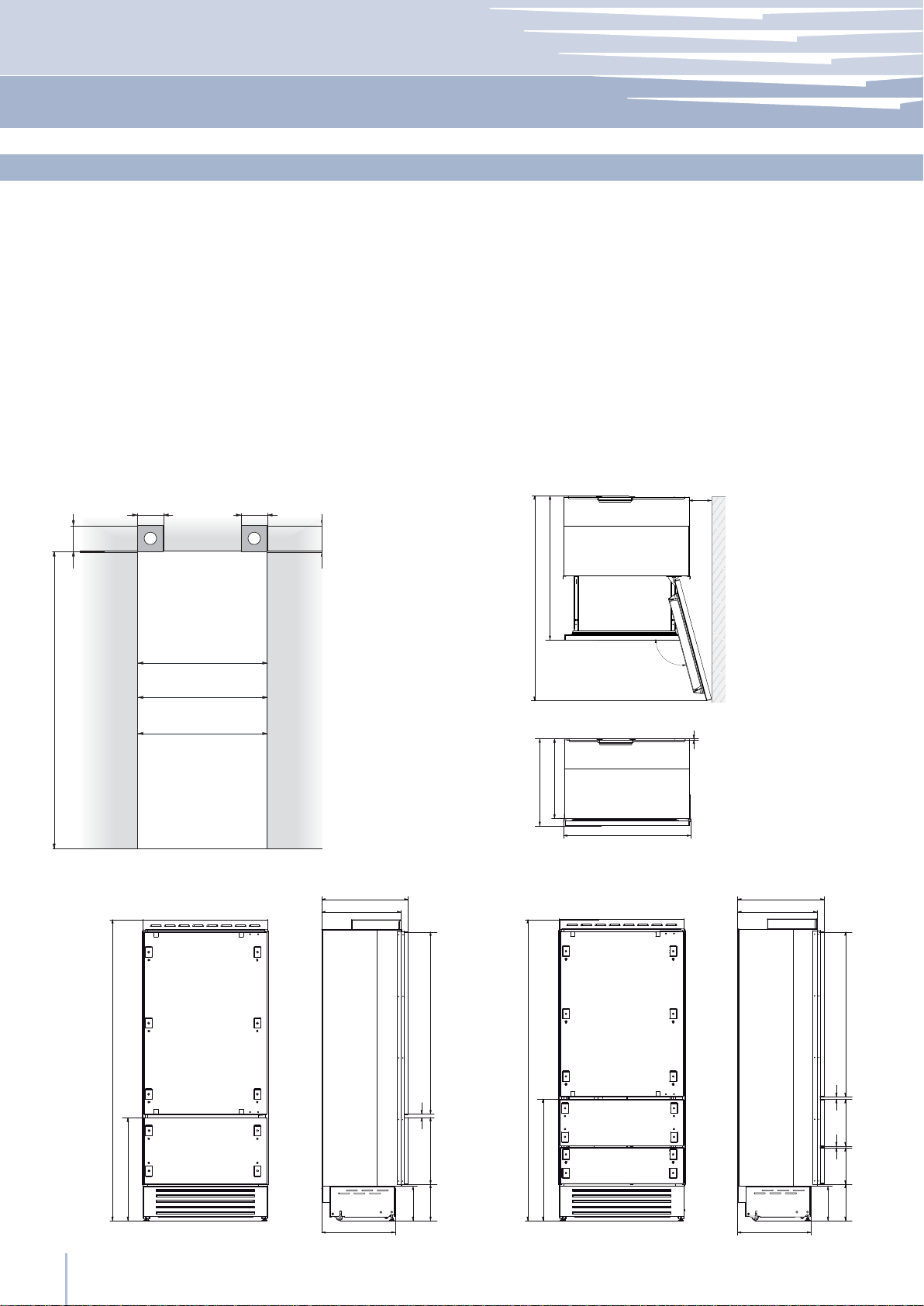
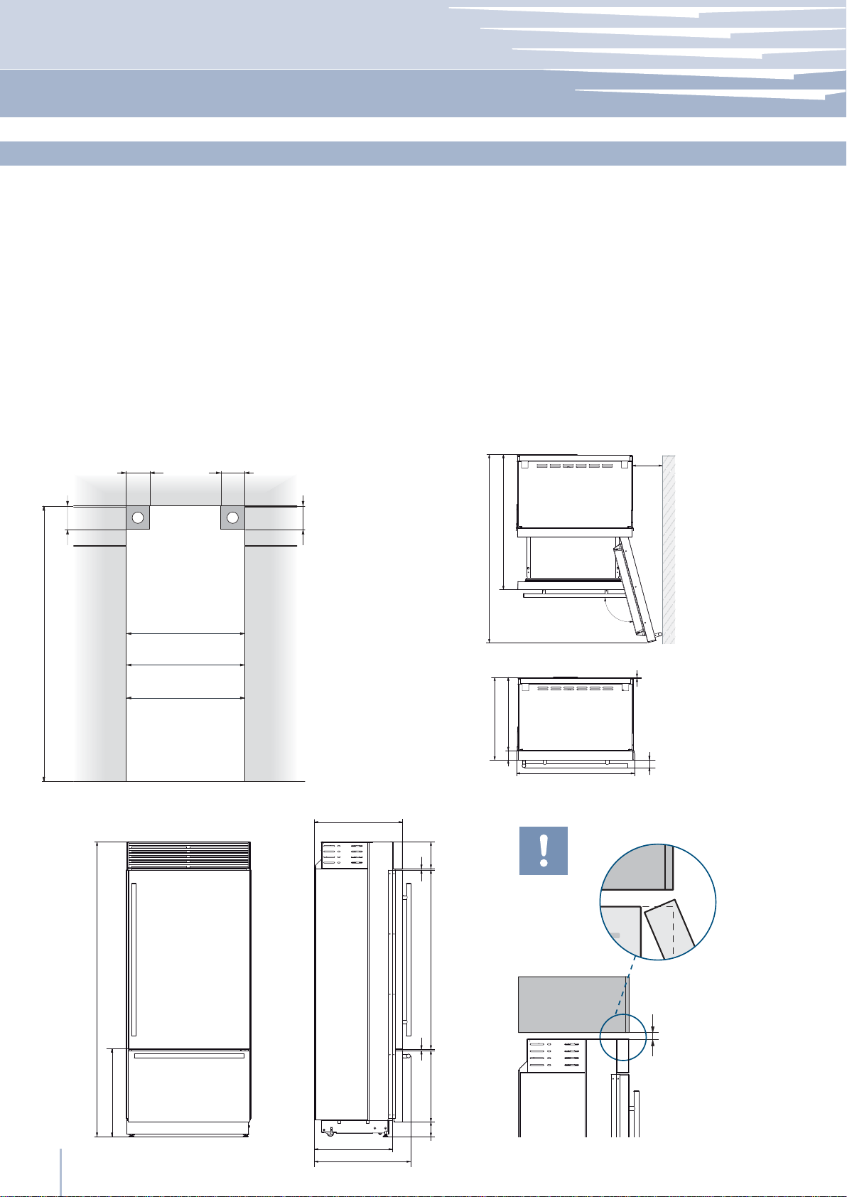
Installation niche features: Integrated Series
A
area to be left clear for the anti-tipping brackets
Niche Height
2134 mm (84”)
Niche Width
FI36: 900 mm (35 1/2”)
FI30: 750 mm (29 5/8”)
FI24: 600 mm (23 3/4”)
Door Swing Clearance
FI36: 1470 mm (57 7/8”)
FI30: 1320 mm (52”)
FI24: 1170 mm (46”)
Door Opening Angle
105°
Width
FI36: 899 mm (35 3/8”)
FI30: 749 mm (29 1/2”)
FI24: 599 mm (23 5/8”)
Height
2120 mm (83 1/2”) + 25 mm (1”)
Depth with door (without panel)
610 mm (24”)
140 (5 ½”) 140 (5 ½”)
100 (4”)
min 2134 (84”)
A A
FI36: 900 (35 ½”)
FI30: 750 (29 ⁄”)
FI24: 600 (23 ¾”)
100 (4”)
610 (24”)
560 (22”)
992 (39”)
FI30: 1320 (52”)
FI24: 1170 (46”)
FI36: 1470 (57 ⁄”)
560 (22”)
610 (24”)
FI36: 79 (3 ⁄”)
FI30: 53 (2 ⁄”)
FI24: 27 (1 ⁄”)
105°
10 (⁄”)
FI36: 899 (35 ⁄”)
FI30: 749 (29 ½”)
FI24: 599 (23 ⁄”)
610 (24”)
560 (22”)
2120 (83 ½”) +25 (1”)
721 (28 ⁄”) +25 (1”)
www.fhiaba.com · www.thevettagroup.com
4
1293 (50 ⁄” )
20 (¾”)
474 (18 ⁄”)
25 (1”)
+ 25 (1”)
500 (19 ¾”) 500 (19 ¾”)
) +
)
⁄”
¾”
231 (9
248 (9
2120 (83 ½”) +25 (1”)
846 (33 ¼”) +25 (1”)
1168(46”)
20 (¾”)10 (⁄”)
25 (1”)
+ 25 (1”)
) +
)
⁄”
¾”
231 (9
248 (9
330 (13”)
)
¼”
259 (10
Installation niche features: StandPlus Series
A
area to be left clear for the anti-tipping brackets
Niche Height
2134 mm (84”)
Niche Width
FM36: 900 mm (35 1/2”)
FM24: 600 mm (23 3/4”)
Door Swing Clearance
FM36: 1470 mm (57 7/8”)
FM24: 1170 mm (46”)
Installation Guide
Door Opening Angle
105°
Width
FM36: 899 mm (35 3/8”)
FM24: 599 mm (23 5/8”)
Height
2120 mm (83 1/2”) + 25 mm (1”)
Depth with door
629 mm (24 3/4”)
140 (5 ½”) 140 (5 ½”)
100 (4”)
min 2134 (84”)
A A
FM36: 900 (35 ½”)
FM24: 600 (23 ¾”)
100 (4”)
629 (24 ¾”)
615 (24 ¼”)
FM36: 120 (4 ¾”)
FM24: 68 (2 ⁄”)
EnglishFrançais
1010 (39 ¾”)
FM24: 1170 (46”)
FM36: 1470 (57 ⁄”)
105°
10 (⁄”)
560 (22”)
629 (24 ¾”)
FM36: 899 (35 ⁄”)
FM24: 599 (23 ⁄”)
69 (2 ¾”)
IMPORTANT
8 (⁄”)
195 (7 ⁄”)
37 (1 ½”)
2120 (83 ½”) +25 (1”)
613 (24 ⁄”)+25 (1”)
560 (22”)
666 (26 ¼”)
1296 (50”)
8 (⁄”)
485 (19 ⁄”)
128 (5) + 25 (1”)
Flush
min 10 (⁄”)
www.fhiaba.com · www.thevettagroup.com
5
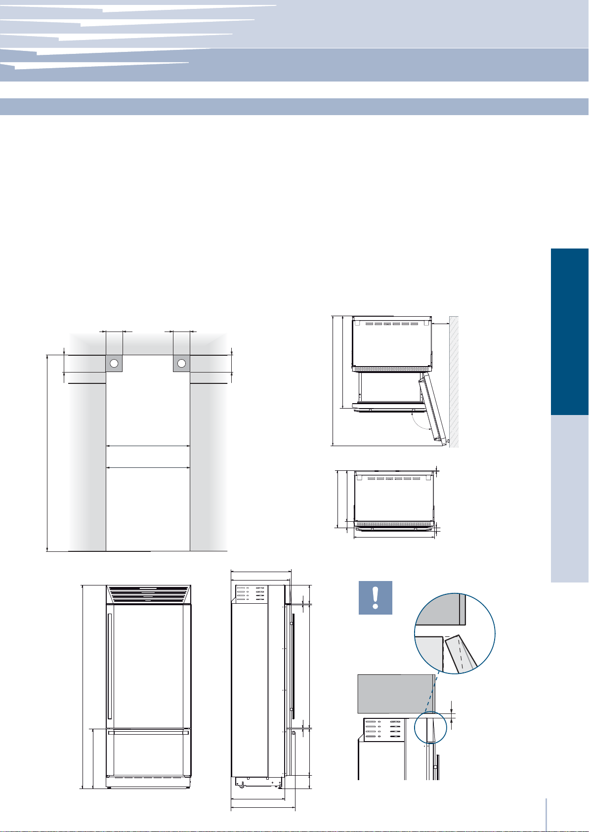
Installation niche features: X-Pro Series
A
area to be left clear for the anti-tipping brackets
Niche Height
2134 mm (84”)
Niche Width
FP36: 900 mm (35 1/2”)
FP30: 750 mm (29 5/8”)
FP24: 600 mm (23 3/4”)
Door Swing Clearance
FP36: 1470 mm (57 7/8”)
FP30: 1320 mm (52”)
FP24: 1170 mm (46”)
Door Opening Angle
105°
Width
FP36: 899 mm (35 3/8”)
FP30: 749 mm (29 1/2”)
FP24: 599 mm (23 5/8”)
Height
2120 mm (83 1/2”) + 25 mm (1”)
Depth with door
635 mm (25”)
140 (5 ½”) 140 (5 ½”)
100 (4”)
min 2134 (84”)
A A
FP36: 900 (35 ½”)
FP30: 750 (29 ⁄”)
FP24: 600 (23 ¾”)
100 (4”)
635 (25”)
FP36: 138 (5 ½”)
FP30: 112 (4 ⁄”)
FP24: 86 (3 ⁄”)
1016 (40”)
FP30: 1320 (52”)
FP24: 1170 (46”)
FP36: 1470 (57 ⁄”)
105°
10 (⁄”)58 (2 ¼”)
635 (25”)
560 (22”)
FP36: 899 (35 ⁄”)
75 (3”)
FP30: 749 (29 ½”)
FP24: 599 (23 ⁄”)
IMPORTANT
8 (⁄”)
195 (7 ⁄”)
2120 (83 ½”) +25 (1”)
613 (24 ⁄”)+25 (1”)
www.fhiaba.com · www.thevettagroup.com
6
560 (22”)
693 (27 ¼”)
1296 (50”)
8 (⁄”)
485 (19 ⁄”)
128 (5) + 25 (1”)
min 10 (⁄”)
Flush
Installation Guide
Series: All
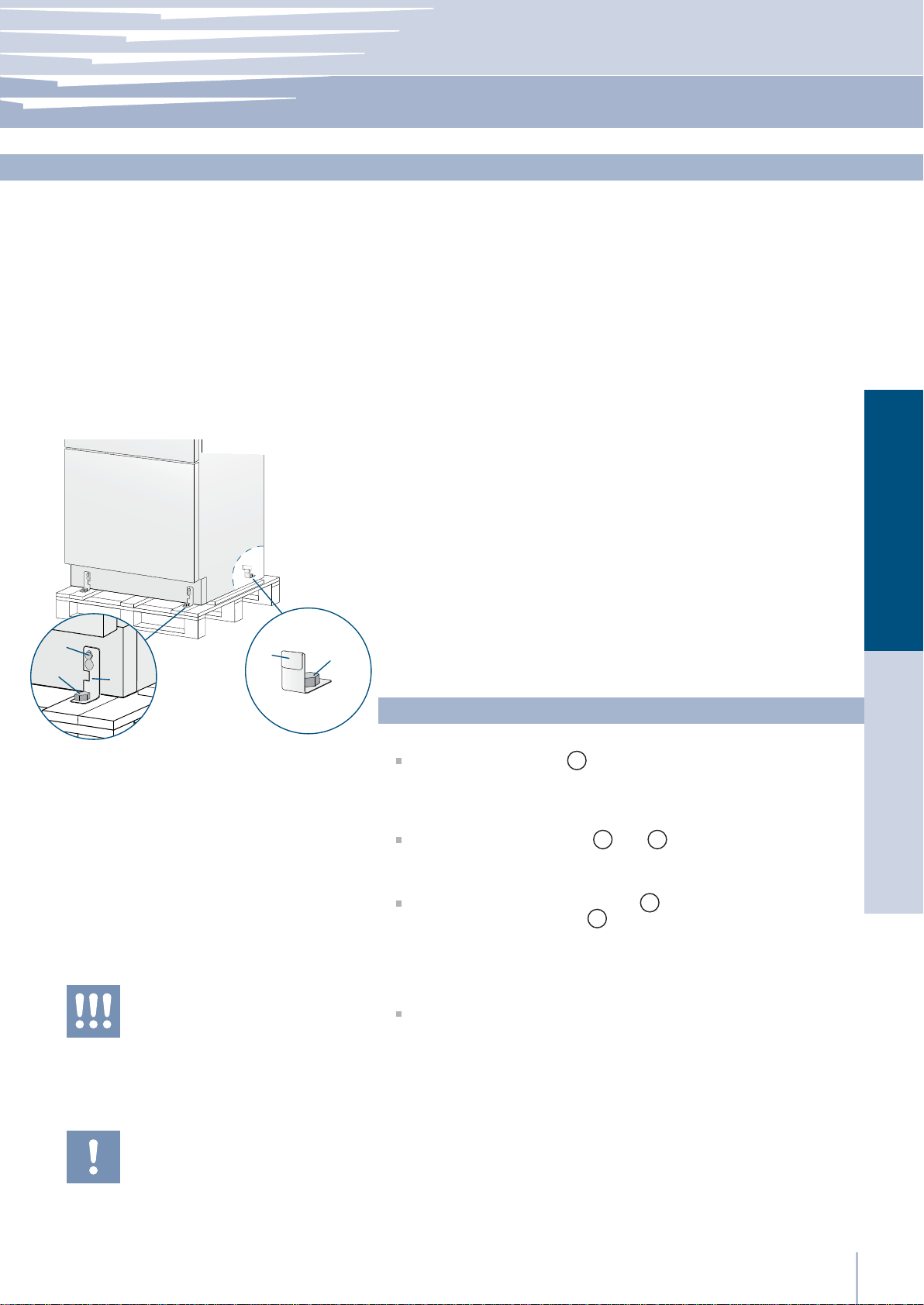
Preparing the installation
Transport to installation site
and unpacking
2
1
3
4
1
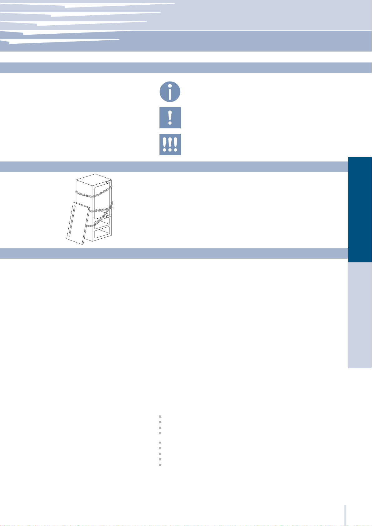
Since this is a large and heavy appliance, before transporting the appliance, check the access to the location where it will be installed
(door size, manoeuvring space in stairwells, etc.).
The appliance is attached to the base of the packaging (pallet) through
four bolts which can be removed using a 17 mm (3/4”) wrench.
It is recommended to use a manual transporting device to move the
appliance to the installation site, and only at this point to remove the
base of the packaging.
The appliance should always be transported in an erect position.
If this is not possible, transport the appliance laying on its rear side.
Once at the installation site, the appliance, which is equipped with four
wheels, can be taken off the pallet and positioned in the installation
area.
Operate as follows:
EnglishFrançais
The appliance is very heavy.
Take maximum care during handling to
avoid injury.
The appliance should always be transported in an erect position.
Avoid at all costs leaning it on its front side.
Take off the four bolts
means of a 17 mm (3/4”) open spanner.
Remove the À xing brackets 3 and 4.
To remove the front À xing bracket 3 , unscrew for one or two turns
the rear wheel adjusting bolt 2 by means of a 13 mm (1/2”) box spanner.
From the back of the unit and by means of a suitable, high duty hand
trolley, take off the appliance and place it on the Á oor .
Be very careful to avoid any damage to Á oors. Delicate Á oors should be
protected with plywood, hard cardboard or similar material panels.
securing the appliance to the pallet by
1
www.fhiaba.com · www.thevettagroup.com
7
Series: All
Niche Dimensions and Installation Styles: Integrated Series
FI36: 900 (35 ½”)
Series
FI30: 750 (29 ⁄”)
FI24: 600 (23 ¾”)
AAB
A KCLITU: Lateral connection Kit
(not included - must be ordered as a
separate accessory)
B KCCITU: Central connection Kit
(not included - must be ordered as a
separate accessory)
FI36
FI30
FI24
750 (29 5/8”)
600 (23 3/4”)
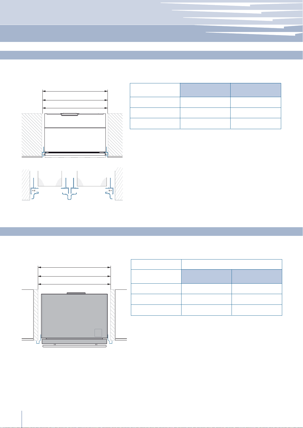
Niche Dimensions and Installation Styles: StandPlus and X-Pro Series
Panels WidthNiche
897 (35 1/4”)900 (35 1/2”)
747 (29 3/8”)
597 (23 1/2”)
Stand-Proud
36: 914 (36”)
30: 762 (30”)
24: 610 (24”)
Series
36
30
24
KCLXB: Lateral connection Kit
(not included - must be ordered as a
separate accessory)
900 (35 1/2”)
750 (29 5/8”)
600 (23 3/4”)
NICHE
MAXMIN
914 (36”
762 (30”)
610 (24”)
)
www.fhiaba.com · www.thevettagroup.com
8
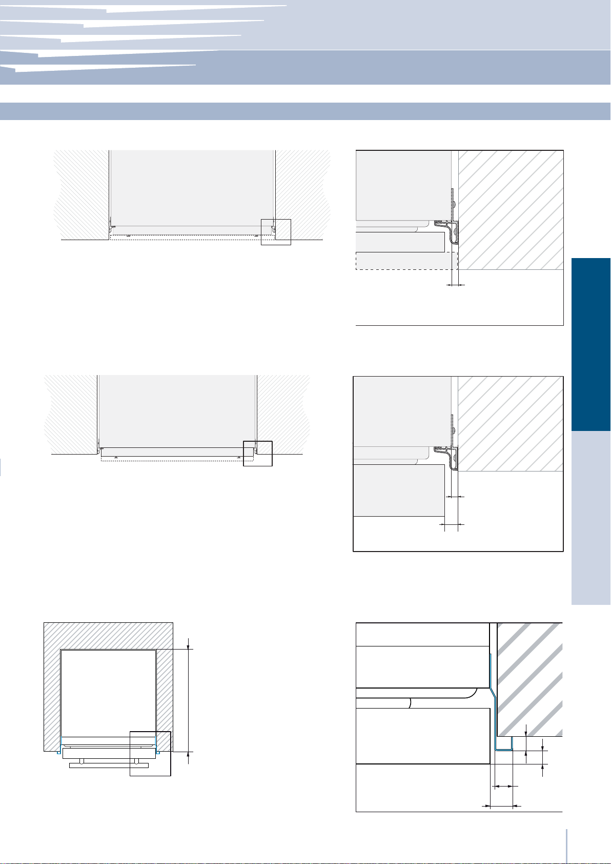
Flush installation with standard aluminum trims
Installation Guide
Series: All
Installation types
A
A KCLITU: Lateral connection Kit
(not included - must be ordered as a
separate accessory)
B KCCITU: Central connection Kit
(not included - must be ordered as a
separate accessory)
Prominent installation with standard aluminum trims
A KCLITU: Lateral connection Kit
(not included - must be ordered as a
separate accessory)
B KCCITU: Central connection Kit
(not included - must be ordered as a
separate accessory)
B
6,5 (¼”)
EnglishFrançais
A
B
6,5 (¼”)
10 (⁄”)
Stand-Proud (for StandPlus and X-Pro series)
Niche 610 mm (24”)
610 (24”)
KCLXB: Lateral connection Kit
(not included - must be ordered as a
separate accessory)
)
⁄”
15 (
)
20 (¾”)
25 (1”)
www.fhiaba.com · www.thevettagroup.com
⁄”
10 (
9
Series: All
Electrical and Water connection
EW
E W
E W
The appliances are delivered from the factory for operation at 110V120V AC - 60Hz (US and Canada).
They are provided with a suitable supply cable and plug to be connected to an appropriate 15A socket (US and Canada) provided
with an effective grounding.
A circuit breaker should also be installed and should be easily accessible so that it can be easily switched off before performing any
installation or maintenance.
To connect to the water supply system (for appliances equipped with
ice makers) a 1/4” waterline with accessible shut-off valve must be
supplied.
The appliance is provided with a water adapter elbow which is suitable for high water pressure and complies the Food Regulations.
The water À lter cartridge, which is provided with the appliance,
should be installed according to the accompanying instructions. Use
only the new adapter which is supplied with the appliance. The solenoid connection on the appliance is 3/4” diameter but is metric
threaded. A standard garden hose threaded connector such as a
braided stainless hose found at typical hardware stores will strip or
damage the solenoid threads. Use only the supplied 1/4” quick connect elbow adapter for connecting a 1/4” copper or polyethylene
source water line to the appliance.
EW
The Built-in Fhiaba À lter cannot make it safe
to drink any water which is not suitable for
human consumption.
The appliance should be connected only to
a drinkable water supply system.
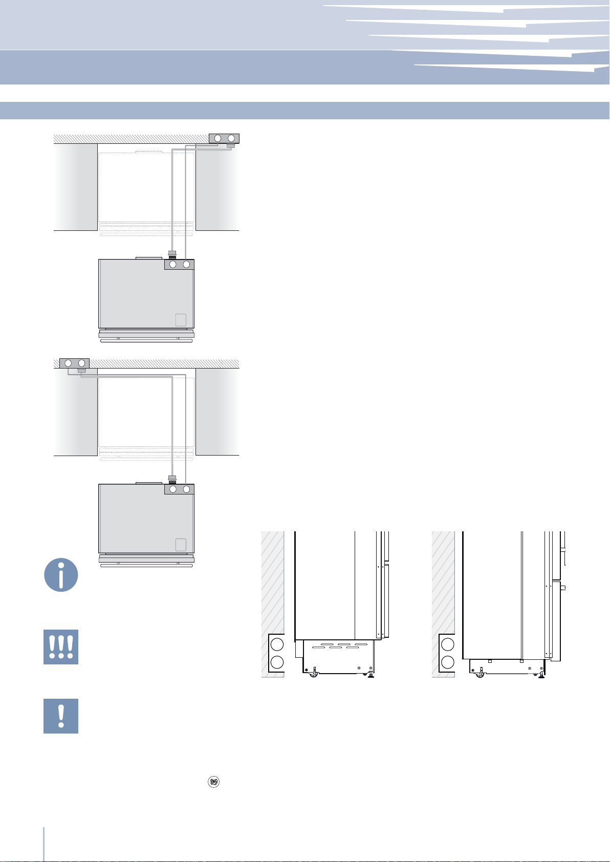
Electrical cord length: 2500 mm (98 3/8”)
Water connection line length: 2500 mm (98 3/8”)
Electrical and water supply behind the unit
Integrated Series StandPlus and X-Pro Series
E
W
E
W
Do not use extension cords or adapters.
Once the appliance is fully installed, connected to the water supply (if applicable) and
operational, in the event that the water supply must be turned off,(touch the button
control panel to switch it off) before the main
water is shut off to prevent the appliance from
entering a ‘NO WATER IN’ alarm state.
www.fhiaba.com · www.thevettagroup.com
10
on
Electrical connection
Water connection
Installation Guide
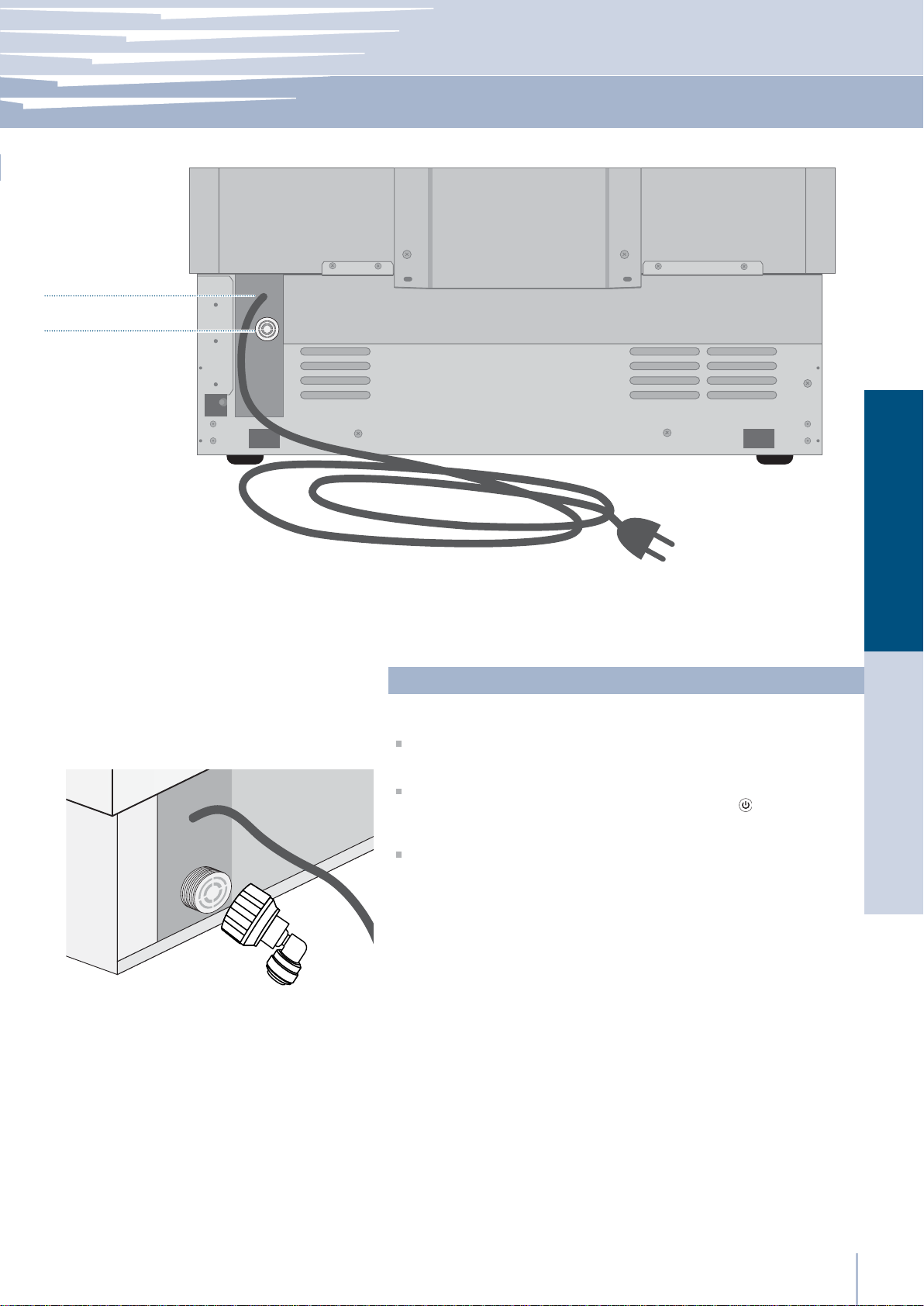
Series: Integrated
Back of appliance
Operate as follows:
Unwind the electric cable and connect it directly to the wall socket.
Make sure the appliance is in the Stand-by condition and that all
lights are off; should it be not so press the Unit button to switch it off.
Push the 1/4” source waterline fully into the elbow connector then
thread the elbow adapter to the solenoid at the back of the appliance.
Firmly tighten with À ngers - a tool / wrench should not be needed to
make a proper seal. Turn on the water and ensure all connections
are not leaking prior to pushing the unit into the niche.
EnglishFrançais
www.fhiaba.com · www.thevettagroup.com
11
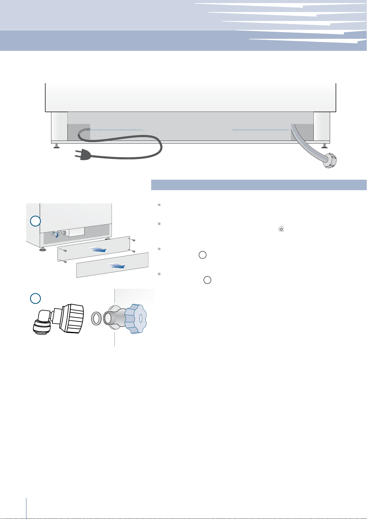
Series: StandPlus/X-Pro
Back of appliance
Water connectionElectrical connection
Operate as follows:
Front of appliance
1
2
Unwind the electric cable and connect it directly to the wall socket.
Make sure the appliance is in the Stand-by condition and that all ights
are off; should it be not so press the Unit button to switch it off.
Connect the water line to the threaded connection at the base of the
unit, as in À gure 1.
Fit the other end of the hose to the water tap, use the gaskets provided
in the Owner’s Kit 2.
Firmly tighten with À ngers - a tool / wrench should not be needed to
make a proper seal. Turn on the water and ensure all connections are
not leaking prior to pushing the unit into the niche.
www.fhiaba.com · www.thevettagroup.com
12
Installation Guide
Series: All
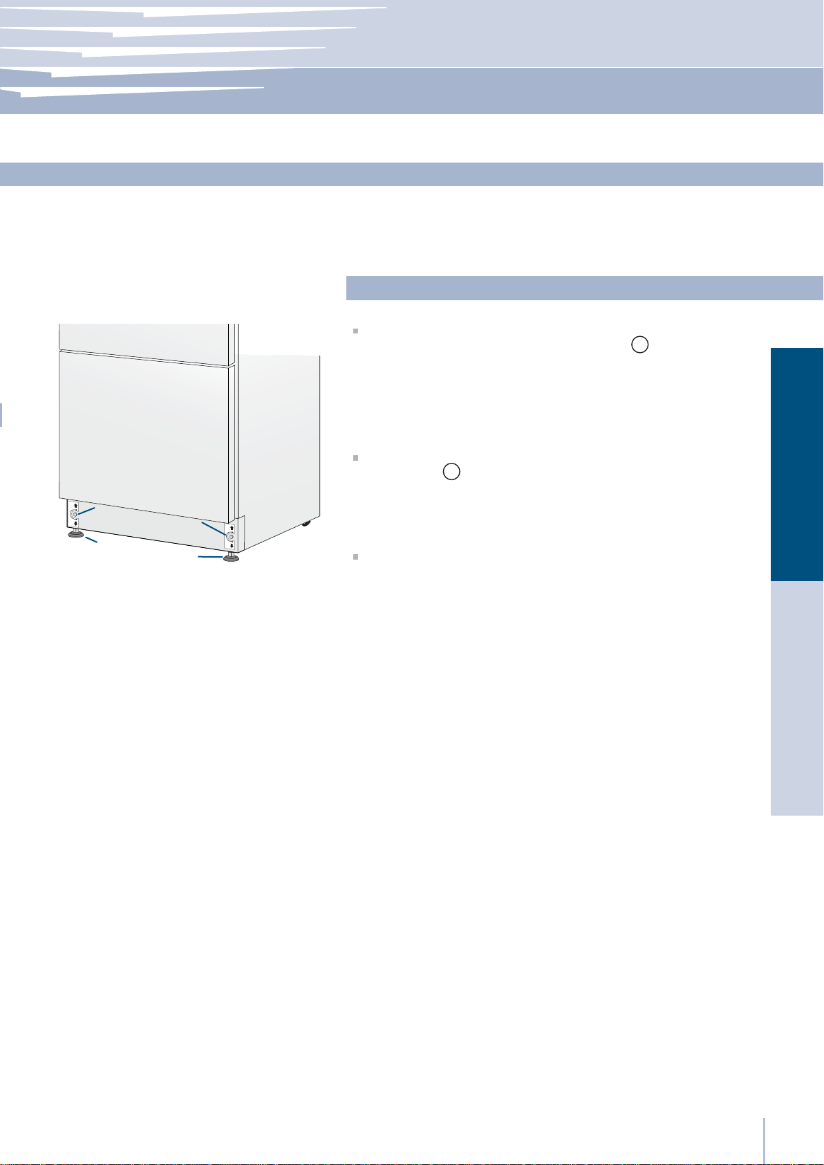
Levelling
Adjust the appliance level by means of the front levelling feet
and the rear adjustable wheels.
Operate as follows:
After removing the bottom plinth or grille (it is kept in position by
magnets), adjust the height of the levelling feet 1 by means of a 17
mm (3/4”) open spanner.
2
1
2
1
Then adjust the height of the rear wheels by turning the front
adjusting bolts 2 clockwise or anticlockwise as it may be required.
EnglishFrançais
Remount the bottom plinth or grille.
www.fhiaba.com · www.thevettagroup.com
13
Series: Integrated
Decorative door and bottom-drawer panels layout
The dimensions of the panels are indicated in the table and drawings on pages 16-19.
Nevertheless, according to the requirements for aligning with other
kitchen structures, the door panel can be higher than the upper
edge of the refrigerator door, and the drawer panel can be lower
than the edge of the drawer.
The panels must be mounted using special braces which attach
to adjustable devices provided on the door and drawer and with
brackets that anchor and adjust the panel’s vertical direction.
Braces, brackets and fixing screws are provided with the appliance
and must be applied to the panel as indicated.
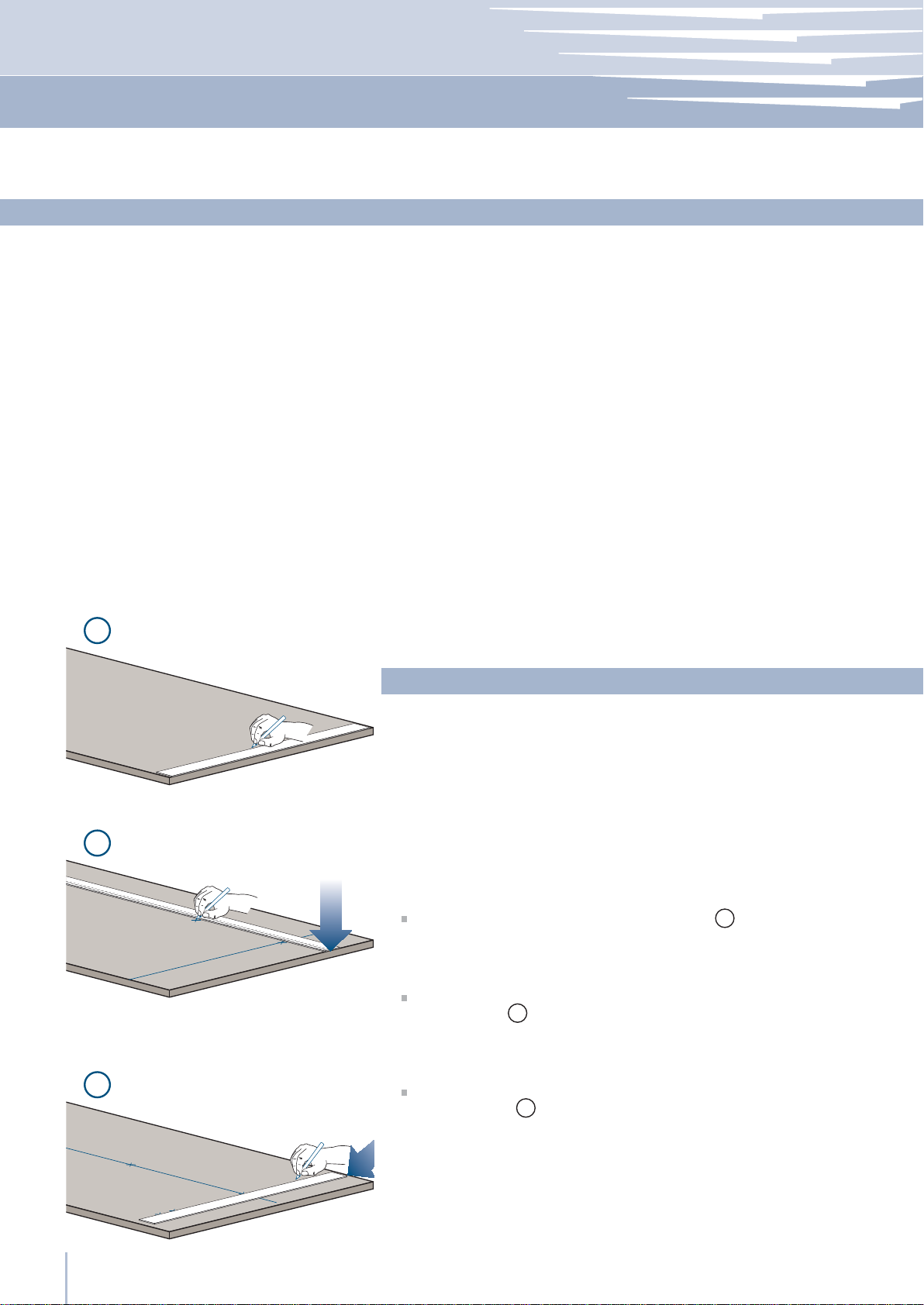
1
Operate as follows:
To prepare the panels to be mounted on the appliance, follow
these steps, working on the back of the panel.
2
Door Panel
Trace, a line dividing the panel width in half 1.
Starting form the Bottom edge of the panel, mark the positioning
of the brackets 2.
3
www.fhiaba.com · www.thevettagroup.com
14
Following the corresponding table, mark the external and then
the internal hole 3.
Installation Guide
Series: Integrated
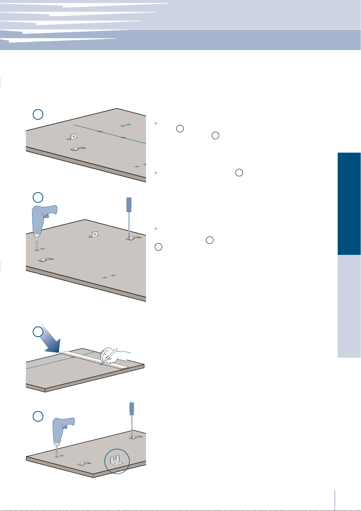
4
Position the brackets on each set of marks to make sure they are
aligned 4, then drill holes through the panel (pay close attention to
the panel’s thickness)5.
Screw the brackets in place 6.
5
Drawer Panel
When preparing the Drawer Panel, follow the same instructions as
per the door panel, but make sure measurements are taken starting
from the top edge 7. The support bracket faces the opposite way
(note imgs 4 and 8).
8
EnglishFrançais
7
8
www.fhiaba.com · www.thevettagroup.com
15
Series: Integrated
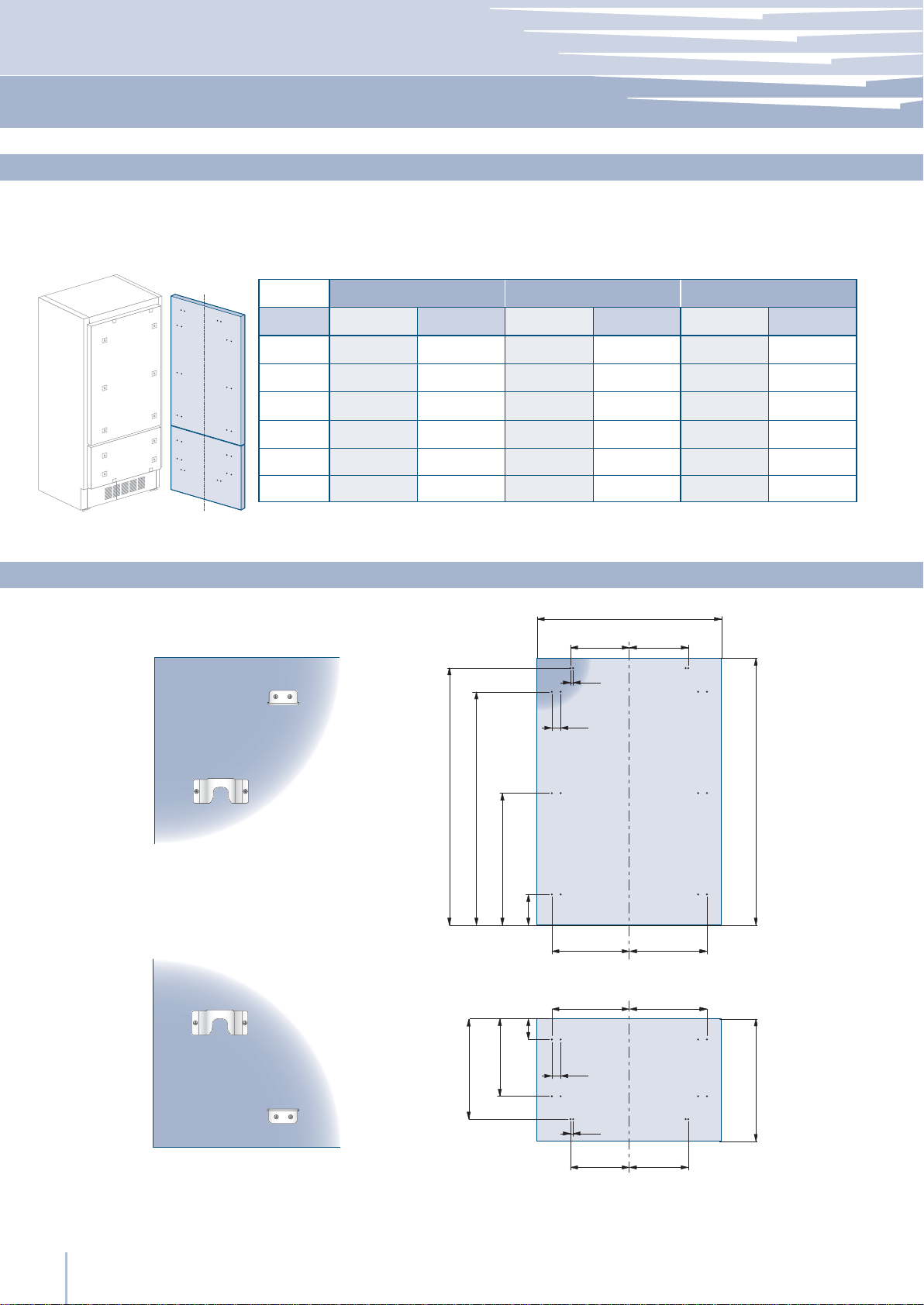
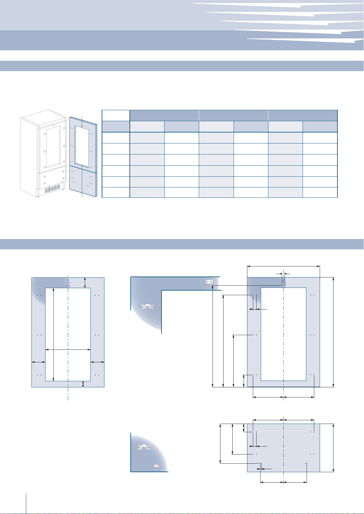
Decorative panels layout for Fridge with one Bottom-Drawer
Series 36
Hinge Left Hinge Left Hinge Left
A
B
C
D
E
897 (35 ¼”)
355.5 (14”)
418 (16
354.5 (14”) 354.5 (14”) 279.5 (11”) 279.5 (11”) 203.5(8”)
Hinge Right Hinge Right Hinge Right
897 (35 ¼”) 747 (29
261 (10
¼”)
355.5 (14”)
½”)
386 (15
418 (16
¼”)
½”)
Series 30 Series 24
⁄”) 747 (29 ⁄”) 597 (23 ½”)
279 (11”)
187 (7
343 (13
311 (12
⁄”)
½”)
¼”)
187 (7
279 (11”)
311 (12
343 (13
⁄”)
¼”)
½”)
205 (8
111 (4
276.5 (10 ⁄”)
236.5 (9
⁄”)
⁄”)
⁄”)
597 (23 ½”)
111 (4
⁄”)
⁄”)261 (10 ¼”)
205 (8
236.5 (9 ⁄”)
276.5 (10 ⁄”)386 (15 ¼”)
203.5(8”)F / G
Holes positions
A
B C
13 (½”)
⁄”)
34 (1
¾”)
1285 (50 ⁄”)
1163 (45
507.5 (20”)
¼”)
660 (26”)
157 (6
⁄”)
100 (4”)
382 (15
D E
D E
⁄”)
34 (1
½”)
13 (
F G
¾”)max 635 (25”)
min 1390 (54
www.fhiaba.com · www.thevettagroup.com
16
Installation Guide
Series: Integrated
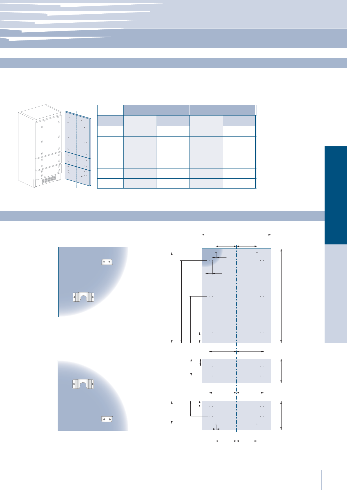
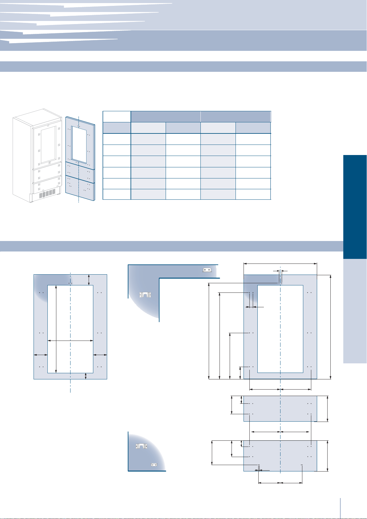
Decorative panels layout for Fridge with two Bottom-Drawers
A
B
C
D
E
F / G
Series 36
Hinge Left Hinge Left
897 (35 ¼”)
355.5 (14”)
261 (10 ¼”)
418 (16
354.5 (14”) 354.5 (14”) 279.5 (11”) 279.5 (11”)
Hinge Right Hinge Right
897 (35 ¼”) 747 (29
261 (10
¼”)
355.5 (14”)
½”)
386 (15
418 (16
¼”)
½”)
Series 30
⁄”) 747 (29 ⁄”)
279 (11”)
⁄”)
187 (7
½”)
343 (13
311 (12
¼”)
187 (7
279 (11”)
311 (12
343 (13
Holes positions
A
B C
½”)
13 (
34 (1
⁄”)
⁄”)
¼”)
½”)386 (15 ¼”)
EnglishFrançais
⁄”)
⁄”)
1160 (45
1044 (41
½”)
268 (10
½”)
292,5 (11
¼”)
183 (7
⁄”)
600 (23
⁄”) 157 (6 ¼”)
66 (2
⁄”)
73 (2
min 1265 (49 ¾”)
D E
¼”)max 415 (16 ⁄”)
337 (13
D E
13 (½”)
F G
www.fhiaba.com · www.thevettagroup.com
17
Series: Integrated
Decorative panels layout for Fridge with glass door and one Bottom-Drawer
F / G
<200 (7 ⁄”)
Series 36
Hinge Left Hinge Left Hinge Left
A
D
E
H
I
897 (35 ¼”) 897 (35 ¼”)
418 (16
354.5 (14”) 354.5 (14”) 279.5 (11”) 279.5 (11”) 203,5(8”) 203,5(8”)
412 (16
Hinge Right Hinge Right Hinge Right
½”)
¼”)
386 (15
418 (16
380 (15”)
412 (16
¼”)
½”)
¼”)
Series 30
747 (29 ⁄”) 747 (29 ⁄”) 597 (23 ½”) 597 (23 ½”)
½”)
¼”)
311 (12 ¼”)
343 (13 ½”)
305 (12”)
337 (13
¼”)
270.5 (10 ⁄”)
343 (13
311 (12 ¼”)
337 (13
305 (12”)
Series 24
276.5 (10
236.5 (9 ⁄”)
230.5 (9
⁄”)
⁄”)
236.5 (9
276.5 (10 ⁄”)386 (15 ¼”)
230.5 (9 ⁄”)
270.5 (10
⁄”)
⁄”)380 (15”)
Holes positionsDoor window dimensions
A
6,5 (
¼”)
6,5 (¼”)
135 (5
1075 (42 ⁄”)
36: 627 (24 ¾”)
30: 477 (18
24: 327 (12
⁄”)
¾”)
⁄”)
135 (5
115 (4
⁄”)
½”)
⁄”)
1286 (50 ⁄”)
1152,5 (45
507,5 (20”)
⁄”)
⁄”)
650,5 (25
148,5 (5
⁄”)
100 (4”)
382 (15
34 (1
⁄”)
H I
D E
⁄”)
34 (1
13 (
½”)
F G
min 1390 (54 ¾”)
max 635 (25”)
www.fhiaba.com · www.thevettagroup.com
18
Installation Guide
Series: Integrated
Decorative panels layout for Fridge with glass door and two Bottom-Drawers
A
D
E
F / G
H
I
<200 (7 ⁄”)
Series 36
Hinge Left Hinge Left
897 (35 ¼”) 897 (35 ¼”)
418 (16
386 (15
354.5 (14”) 354.5 (14”) 279.5 (11”) 279.5 (11”)
412 (16
380 (15”)
Hinge Right Hinge Right
½”)
¼”)
¼”)
386 (15
418 (16
380 (15”)
412 (16
¼”)
½”)
¼”)
Series 30
747 (29 ⁄”) 747 (29 ⁄”)
½”)
¼”)
311 (12 ¼”)
343 (13 ½”)
305 (12”)
337 (13
¼”)
343 (13
311 (12 ¼”)
337 (13
305 (12”)
Holes positionsDoor window dimensions
6,5 (
¼”)
EnglishFrançais
A
6,5 (¼”)
135 (5
⁄”)
950 (37 ⁄”)
36: 627 (24 ¾”)
30: 477 (18
24: 327 (12
¾”)
⁄”)
135 (5
115 (4
⁄”)
½”)
⁄”)
1161 (45 ¾”)
1026,7 (40
½”)
292,5 (11
⁄”)
⁄”)
588 (23
149,5 (5
⁄”)
66 (2
268 (10 ½”)
⁄”)
73 (2
¼”)
183 (7
⁄”)
34 (1
H I
D E
13 (½”)
F G
min 1265 (49 ¾”)
¼”)
337 (13
⁄”)
max 415 (16
www.fhiaba.com · www.thevettagroup.com
19
Series: Integrated
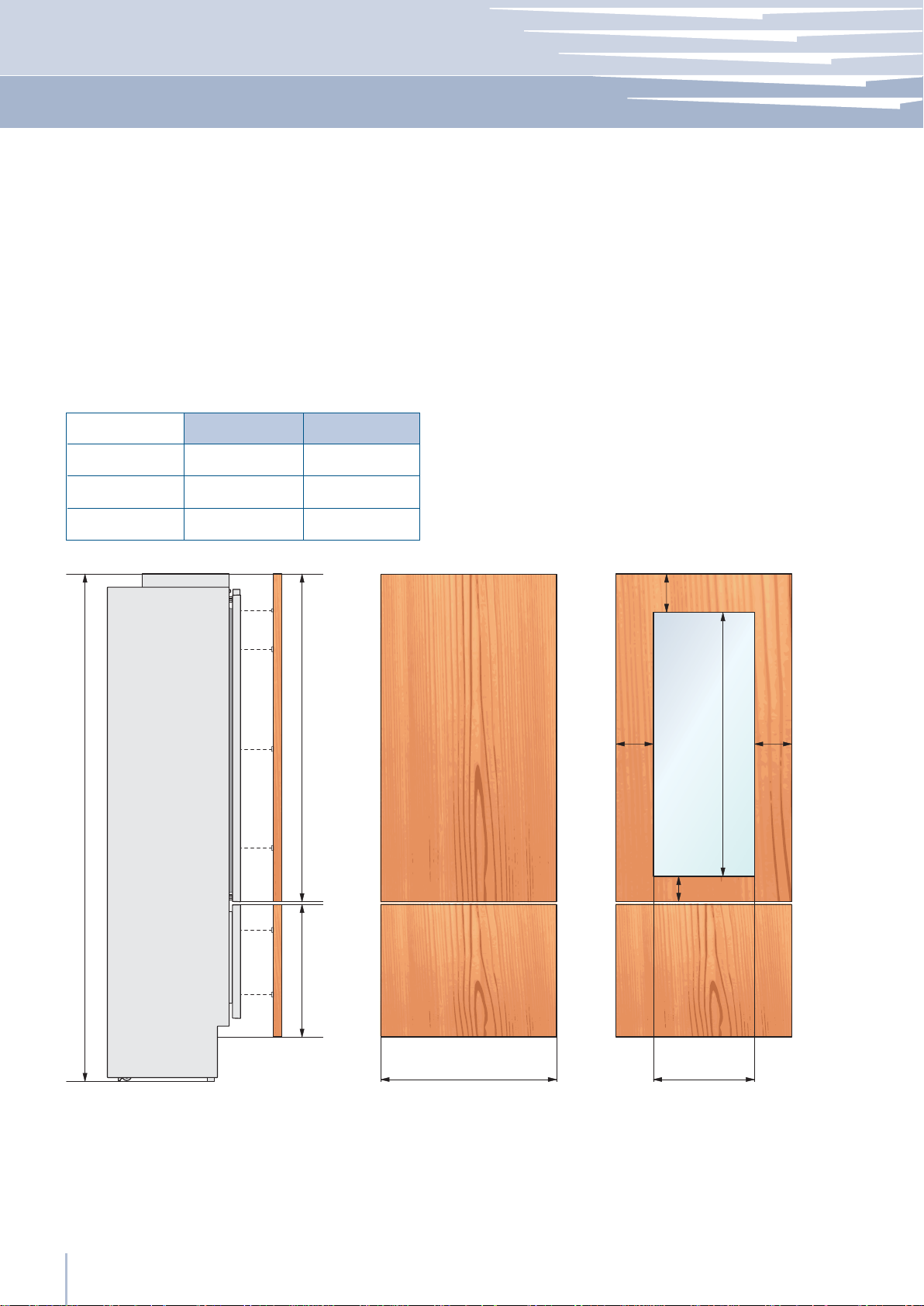
Panels Dimensions Single Bottom - Drawer
Panels can have thickness ranging between 18 mm (3/4”) and 28 mm (1-1/8“).
Door panels can have a maximum weight 23 kg (51 lbs) and drawer panels may be a maximum weight of 11kg (25
lbs)
Exceeding these weights could void your warranty for any service issues which can be attributed to overweight
panels.
The hinging mechanism on Fhiaba appliances is considered to be `Zero-clearance`. The door and drawer widths
specified below assume the minimum niche width is being used and a 3.5mm (1/8”) reveal is desired around the panels.
Adjust your panel dimensions accordingly to your own design criteria considering your niche width and your reveal.
Minimum reveal / gap should not be less than 1.5mm (1/16”).
Series
FI36
FI30
FI24
Door/Drawer Width
Door Cutout Width
A
B
627 (24 3/4”)897 (35 1/4”)
477 (18 3/4”)747 (29 3/8”)
327 (12 7/8”)597 (23 1/2”)
min 200 (7 ⁄”)
135
(5 ⁄”)
1390 (54 ¾”)
1075 (42 ⁄”)
135
(5 ⁄”)
2121 (83 ½") + 25 (1")
Example:
84” niche height
36” niche width
4” toe kick height
1/8” gap desired all around
www.fhiaba.com · www.thevettagroup.com
20
3 (⁄”)
max 635 (25”)
min 540 (21 ¼”)
115 (4 ½”)
A B
Door panel:
Width: 35-3/4”
Height: 54-3/4”
Drawer panel:
Width: 35-3/4”
Height: 84”-1/8”-54-3/4”-1/8”-4”=25”
If you want a 6” toe kick height then your bottom drawer
panel height would be 23”
Installation Guide
Series: Integrated
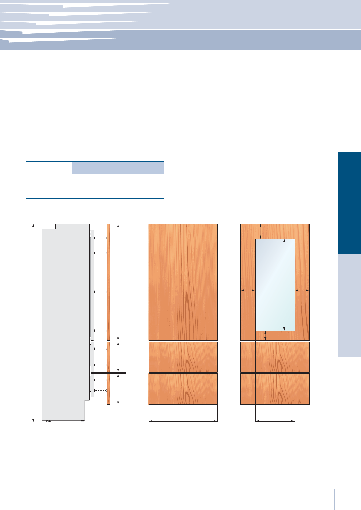
Panels Dimensions Two Bottom - Drawers
Panels can have thickness ranging between 18 mm (3/4”) and 28 mm (1-1/8“).
Door panels can have a maximum weight 23 kg (51 lbs) and drawer panels may be a maximum weight of 11kg (25
lbs)
Exceeding these weights could void your warranty for any service issues which can be attributed to overweight
panels.
The hinging mechanism on Fhiaba appliances is considered to be `Zero-clearance`. The door and drawer widths
specified below assume the minimum niche width is being used and a 3.5mm (1/8”) reveal is desired around the panels.
Adjust your panel dimensions accordingly to your own design criteria considering your niche width and your reveal.
Minimum reveal / gap should not be less than 1.5mm (1/16”).
Series
FI36
FI30
2121 (83 ½") + 25 (1")
Door/Drawer Width
897 (35 1/4”)
747 (29 3/8”)
Door Cutout Width
A
627 (24 3/4”)
477 (18 3/4”)
3 (⁄”)
B
EnglishFrançais
min 200 (7 ⁄”)
135
(5 ⁄”)
115 (4 ½”)
135
(5 ⁄”)
950 (37 ⁄”)
Example:
84” niche height
36” niche width
4” toe kick height
1/8” gap desired all around
337 (13 ¼”) 1265 (49 ¾”)
3 (⁄”)
min 325 (12 ¾”)
max 415 (16 ⁄”)
A B
Door panel:
Width: 35-3/4”
Height: 54-3/4”
Drawer panel:
Width: 35-3/4”
Height: 84”-1/8”-54-3/4”-1/8”-4”=25”
If you want a 6” toe kick height then your bottom drawer
panel height would be 23”
www.fhiaba.com · www.thevettagroup.com
21
 Loading...