

Page 1
Communications Manual
(
(
Series 2000
FGH Controls Ltd
Openshaw Way,Letchworth
Herts. SG6 3ER
Tel:
Fax:
Email: [email protected] www.fgh.co.uk
01462) 686677
01462) 480633
Page 2

SERIES 2000 COMMUNICATIONS MANU AL 1
SERIES 2000 COMMUNICATIONS MANUAL.
CONTENTS.
1.0 GENERAL DESCRIPTION.
1.1 Specification.
1.1.1 2-Wire EIA-485 Mode (RS485)
1.1.2 4-Wire EIA-422-A Mode (RS422)
2.0 CONNECTIONS.
2.1 General.
2.2 2 Wire EIA-485 Mode (RS-485)
2.3 4-Wire EIA-422-A (RS-422)
2.4 Connection reference table
2.5 Software Configuration.
3.0 COMMUNICATIONS PROTOCOL
3.1 Message construction
3.1.1 Write messages
3.1.2 Read messages
3.1.3 Set instrument status messages
3.2 Message header.
3.3 Instrument address.
3.3.1 Wildcard addresses
3.4 Message parameter code.
3.5 Segment number field (P2000 Only).
3.6 Message data field
3.7 Controller read/write parameter codes
3.8 Programmer read/write parameter codes
3.9 Controller Set status codes.
3.10 Programmer Set status codes.
3.11 Response from read or write
3.12 Set status response
3.13 Controller error responses
3.13.1 Corrupt message response
3.13.2 Syntax error response
3.14 Data fields
3.14.1 Data field type 1
3.14.2 Data field type 2.
3.14.3 Data field type 3
3.14.4 Data field type 4 (P2000 Only)
3.14.5 Data field type 5 (P2000 Only)
3.14.6 Data field type 6 (P2000 Only)
3.15 Coded data fields.
3.15.1 Alarm type codes.
3.15.2 Setpoint type codes.
3.15.3 Ratio limit reference type codes.
3.15.4 Hold type codes (P2000 Only)
...........................................................................................................................................................
.....................................................................................................................................................
...................................................................................................................................................................
.....................................................................................................................................................
.............................................................................................................................................................
........................................................................................................................................
.............................................................................................................................
...................................................................................................................................
....................................................................................................................................
..........................................................................................................................................
.............................................................................................................................
.............................................................................................................................................
................................................................................................................................................
................................................................................................................................................
.................................................................................................................................................
..........................................................................................................................................
......................................................................................................................................
..................................................................................................................................................
....................................................................................................................................
...............................................................................................................................
..................................................................................................................................
................................................................................................................................................
....................................................................................................................................
....................................................................................................................................
..............................................................................................................................................
............................................................................................................................................
.............................................................................................................................................
.................................................................................................................................................
..........................................................................................................................................
.......................................................................................................................................
.......................................................................................................................
....................................................................................................................
......................................................................................................................
.....................................................................................................................
...................................................................................................................
...............................................................................................................
..........................................................................................................................
......................................................................................................................
......................................................................................................................
......................................................................................................................
....................................................................................................................
.......................................................................................................................
2
2
2
2
2
2
3
3
4
4
4
4
4
5
5
5
6
6
6
6
6
6
8
8
9
9
9
10
10
10
10
10
11
11
13
13
13
14
14
14
14
15
APPENDIX A - BASIC COMMUNICATIONS PROGRAM
.................................................................................................
M41 Issue 1.1
16
Page 3

2 SERIES 2000 COMMUNICA TIONS M ANUA L
1.0 GENERAL DESCRIPTION.
The FGH S2000 controller or P2000 programmer all have serial communications fitted as
standard. This takes the form of 2 way serial asynchronous communication with a
computer.
Messages consist entirely of ASCII characters and may or may not contain spaces as
desired.
All messages are terminated with a carriage return, <CR>.
2-Wire EIA-485 (RS-485) or 4-Wire EIA-422-A (RS-422) serial communication standards
are supported.
1.1 Specification.
1.1.1 2-Wire EIA-485 Mode (RS485)
Transmission standard: EIA-485 (RS-485)
Data rates: 1200, 2400, 4800 and 9600 baud.
Data format: 1 start, 7 data, odd parity, 1 stop bit.
Implementation: 2 wire half duplex.
Max drivers per line: 32
Max receivers per line: 32
Max cable length: 1200 metres/3937 feet
1.1.2 4-Wire EIA-422-A Mode (RS422)
Transmission standard: EIA-422-A (RS-422)
Data rates 1200, 2400, 4800 and 9600 baud.
Data format 1 start, 7 data, odd parity, 1 stop bit.
Implementation 4 wire half duplex.
Max drivers per line 1
Max receivers per line 10
Max cable length 1200 metres/3937 feet
2.0 CONNECTIONS.
2.1 General.
The series 2000 may be connected to any computer or device which supports the RS422
or RS485 interface standards. This includes any other communicating instruments such
as the series 1000 or any other instrument using the FGH standard protocol.
The instrument uses a balanced voltage communications system which will perform well
under most situations provided some simple guidelines are adhered to.
1. The communications wiring should be implemented using screened cable comprising
one or two twisted pairs. The cable screen should be earthed at one point only.
2. The cable should be routed well away from sources of electrical noise such as motors,
contactors and any other high voltage wiring.
M41 Issue 1.1
Page 4
SERIES 2000 COMMUNICATIONS MANU AL 3
3. The network should be wired as a daisy chain, taking the wires in to one instrument
and hence on to the next. Wiring spurs should be avoided. Take care to continue the
cable screen on to the next instrument.
4. For long cable runs or noisy environments it may be necessary to fit a terminating
resistor to the network. The terminator ( a 220Ω resistor ) should be fitted between
RX+ and RX- on both the computer and the furthest instrument. For two wire networks
this resistor should be fitted at the computer end only. Only one such resistor should
be fitted on each wire pair.
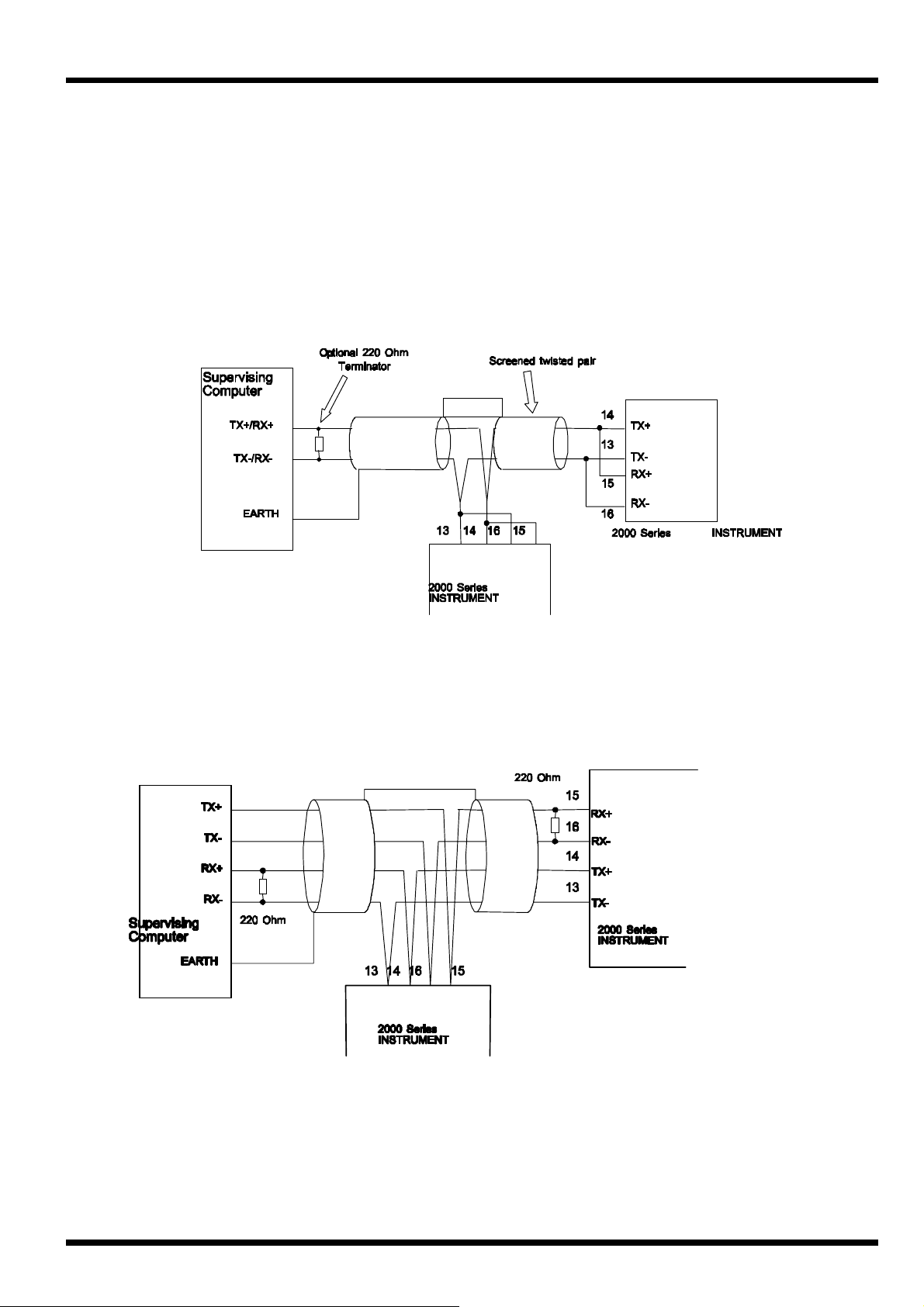
2.2 2 Wire EIA-485 Mode (RS-485)
This diagram shows the connection for EIA-485 mode. Note the use of screened cable. This
connection method may be continued on to other instruments up to the maximum allowed.
2.3 4-Wire EIA-422-A (RS-422)
This diagram shows the connection for EIA-422 mode. Note the use of screened cable.
This connection method may be continued on to other instruments up to the maximum
allowed.
M41 Issue 1.1
Page 5
4 SERIES 2000 COMMUNICA TIONS M ANUA L
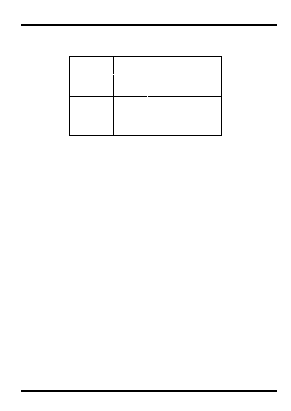
2.4 Connection reference table
Instrument
Terminal
13 TX- TX-/RX- TX-
14 TX+ TX+/RX+ TX+
15 RX+ TX+/RX+ RX+
16 RX- TX-/RX- RX-
1 EARTH N/C or
Function EIA-485 EIA-422-A
N/C or
SCREEN
SCREEN
2.5 Software Configuration.
Software configuration of the instrument may be performed once the instrument has been
placed in 'E mode'. This is done by removing the instrument from its sleeve and setting the
'E mode' switch to ON. The instrument is then replaced in its sleeve and power re-applied.
Use the scroll button (>) to scroll through elements until the
the star button to access the group.
ConS
group is reached. Press
Scroll to the element
9600 using the up/down keys
Scroll to the element
between 0 and 99 using the up/down keys. If the instrument is a P2000 programmer then
the controller part of the instrument will have an address as set by this parameter and the
programmer part of the instrument will have an address which is the controller address plus
16.
bAUd
AddrS
and select the baud rate required from 1200, 2400, 4800 or
. This is the controller instrument address and may be set
3.0 COMMUNICATIONS PROTOCOL
3.1 Message construction
Messages to and from the instrument vary in form depending on, amongst other things, the
type of message and its contents. There are three basic message types:-
3.1.1 Write messages
Write messages to the instrument take the following form.
WAAPSSD..D<CR>
where
M41 Issue 1.1
W
AA
P
SS
D..D
= write message header
= instrument address
= parameter code
= segment number field (P2000 Only)
= numeric data field
Page 6

SERIES 2000 COMMUNICATIONS MANU AL 5
messages to the instrument may have the fields separated by spaces. These spaces will be
ignored. Messages from the instrument will not contain spaces. Eg.
W 45 C 0123 <CR>
will attempt to write 123 to the local set point as well as
W45C0123<CR>
The <CR> at the end of the message is a carriage return. (Hex 0D). Each message written
to the instrument must be terminated with, and each message from the instrument will be
terminated with a carriage return.
3.1.2 Read messages
Read messages to the instrument take the following form.
RAAPSS<CR>
where
Again the message must be terminated with a <CR>, and spaces may be included if
desired.
R
AA
P
SS
= read message header
= instrument address
= parameter code to be read
= segment number (P2000 Only)
3.1.3 Set instrument status messages
Set messages to the instrument take the following form.
SAAC<CR>
where
Again the message must be terminated with a <CR>, and spaces may be included if
desired.
S
AA
C
= set message header
= instrument address
= set parameter code to be performed
3.2 Message header.
This may be;
ASCII R signifying a Read
ASCII W signifying a Write
ASCII S signifying a Set.
The R header is used whenever data is being read from the instrument. When this header
is used the data field is absent. The W header is used to write data to the instrument. The
header is used to set the status of the instrument.
S
M41 Issue 1.1
Page 7

6 SERIES 2000 COMMUNICA TIONS M ANUA L
3.3 Instrument address.
Each instrument must be given a unique address between 0 and 99. This is set when the
instrument is in E mode. The address field of the message, consisting of two ASCII
characters determines to which instrument the message is directed. The instrument ignores
the message unless it corresponds to its own address.
For serial communications purposes, the programmer and controller parts of the
instrument are treated as separate instruments. The controller part will recognise
messages whose address field corresponds exactly with the address programmed in
engineers mode. The programmer part will recognise the programmed address plus 16.
This fact should be borne in mind when assigning controller addresses on the network.
3.3.1 Wildcard addresses
If desired, a group of instruments can be written to together by using a wildcard character
(large X) in place of one or both of the address characters. eg.
W6XC0100<CR>
would result in all instruments on that communication line with addresses of 60 to 69 having
their local set point set to 100.
Instruments written to with wildcard addresses do not reply.
3.4 Message parameter code.
The parameter code field of the message is a single ASCII character. In a write message
this corresponds to one of the control parameters listed in paragraph 4.6, 'parameter codes'.
In the case of set messages, this is still a single ASCII character, but corresponds to one of
the 'set status codes' listed in paragraph 3.7.
3.5 Segment number field (P2000 Only).
This field is used to specify the segment number reference required for some messages to
the profile generator. The segment number should be a two digit field, left padded with a
zero if required.
3.6 Message data field
The message data field consists of between four and eight ASCII characters and carries the
data associated with the specified parameter. There are six types of data field, the type
depending on the particular parameter being accessed. The parameter code tables in
section 3.7 and 3.8 specify the data field format for each parameter.
3.7 Controller read/write parameter codes
Each parameter within the controller is assigned a single alpha code. The meaning of this
code may vary according to the controller action type, eg. heat/cool, motorised valve etc.
M41 Issue 1.1
Page 8

SERIES 2000 COMMUNICATIONS MANU AL 7
Please note that some parameters use coded data fields, the code meanings are listed
after the table.
Code R/W Parameter Scroll
Element
@ R/W Comms remote setpoint - 1
A R Measured variable - 1
B R/W Output in 0.1%
Desired valve position
C R/W Local setpoint SP-L 1
D R/W Propband in 0.1%
Ratio in 0.1%
E R/W Integral action time in S
Ratio low setpoint output limit
F R/W Derivative action time in S
Ratio low thermal head limit
G R/W Derivative approach band in Xp
Ratio approach band
H R/W Heat high power limit in 0.1%
Ratio high air setpoint limit
I R/W Heat TP cycle time in S
Ratio positive reference type
OP
OP
ProP
rAt
IAt
LoOP
dAt
tHLo
APr
bAnd
H-PL
HiOP
HCyC
rEFH
Data field
type
J R/W Alarm 1 level ALr1 1
K R/W Alarm 2 level ALr2 1
L R Controller status - 2
M R/W User Retransmit value - 1
N R Resultant (control) setpoint - 1
O R/W Setpoint type code StyP 1
P R/W Alarm 1 type code A1ty 1
Q R Instrument type code - 3
R R Analogue remote setpoint value - 1
S R/W Alarm 2 type code A2ty 1
T R/W Heat low power limit in 0.1%
Cool high power limit in %
Ratio max thermal head
U R/W Setpoint ramp rate in digits/hour rAtE 1
V R/W Cool TP cycle time in S
Valve action time in S
Ratio negative reference type
W R/W Cool relative prop band in 0.1 rEL 1
X R/W Heat/Cool deadband in 0.1%
Motor valve deadband in 0.1%
Y R/W Auxiliary setpoint 1 SP1 1
Z R/W Auxiliary setpoint 2 SP2 1
L-PL
C-PL
tHHi
CCyC
VAt
rEFL
dbnd
dbnd
1
1
1
1
1
1
1
1
1
1
1
1
1
1
1
1
1
1
1
1
1
1
M41 Issue 1.1
Page 9

8 SERIES 2000 COMMUNICA TIONS M ANUA L
3.8 Programmer read/write parameter codes
The table below shows the meaning of all the parameter codes available in the profile
generator.
PARAMETER
CODE
C N/A Profile setpoint YES TYPE 1
D N/A Delay start time in mins NO TYPE 1
E N/A Segment Elapsed time in mins YES TYPE 1
H N/A Profile hold band in digits NO TYPE 1
I N/A Profile hold type NO TYPE 1
J N/A Profile repeats NO TYPE 1
K N/A Number of repeats remaining YES TYPE 1
L YES Segment target level in digits NO TYPE 1
M N/A Current event status YES TYPE 4
N N/A Ready mode event status NO TYPE 4
P N/A Profile pointer NO TYPE 1
SS
FIELD
MEANING READ
ONLY
DATA
FIELD
(coded)
Q N/A Profile status YES TYPE 5
R YES Segment event outputs NO TYPE 4
T YES Segment time in minutes NO TYPE 6
X N/A Profile currently running YES TYPE 1
3.9 Controller Set status codes.
Writing a set command to the instrument with a parameter as follows will produce the
specified action if the address field matches the address of the instrument. In the examples
given the instrument address is assumed to be 20.
CODE MESSAGE REPLY
M S20M<CR> *20M<CR> Set controller to Manual mode
A S20A<CR> *20A<CR> Set controller to Auto mode
P S20P<CR> *20P<CR> Turn on the pretuner
T S20T<CR> *20T<CR> Turn on the adaptive tuner
O S20O<CR> *20O<CR> Turn off pretuner and adaptive tuner
MEANING
U S20U<CR> *20U<CR> Unlatch any latched alarms
M41 Issue 1.1
Page 10
SERIES 2000 COMMUNICATIONS MANU AL 9
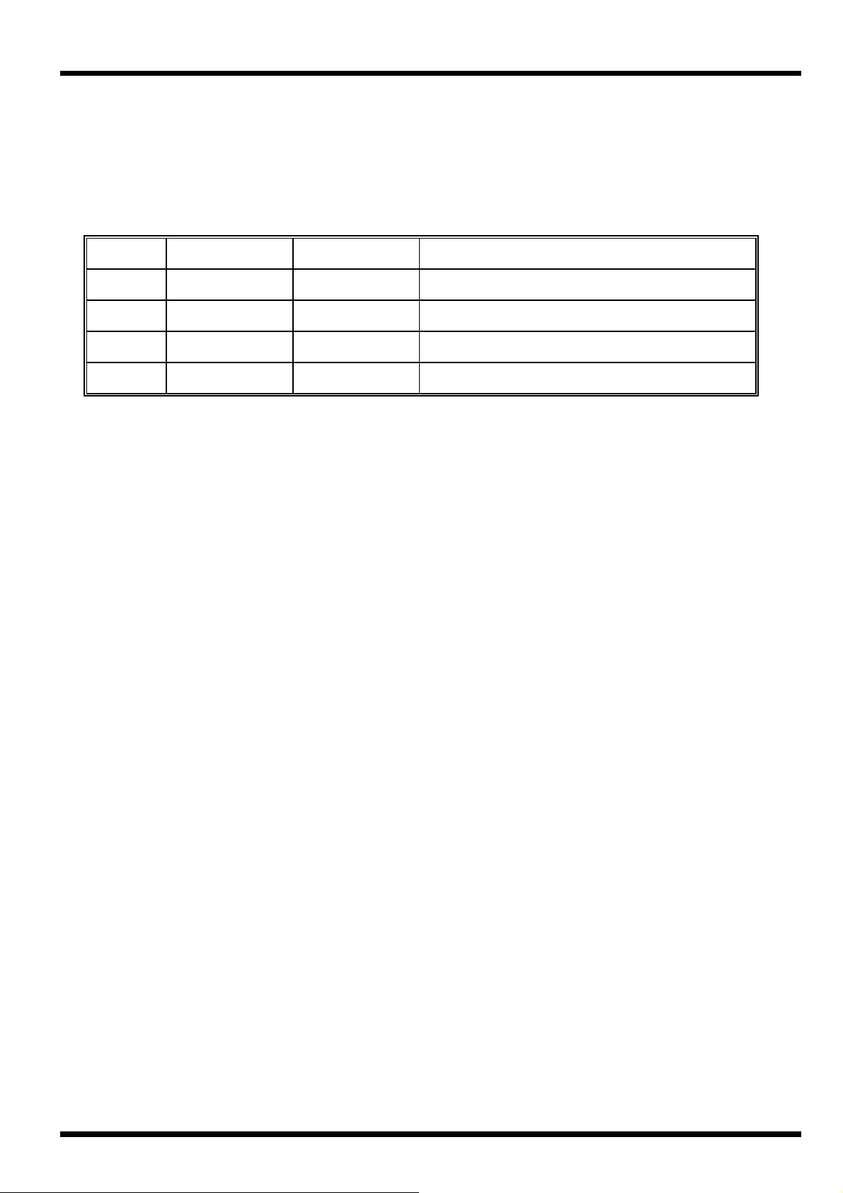
3.10 Programmer Set status codes.
Programmer set commands are signified by the S header as they are for the controller.
There are only four set parameter codes and their meanings are given below.
CODE
S S36S<CR> *36S<CR> Start profile pointed to by profile pointer
R S36R<CR> *36R<CR> Reset currently running profile
H S36H<CR> *36H<CR> Holds (pauses) execution of profile
F S36F<CR> *36F<CR> Frees hold allowing profile to continue
MESSAGE REPLY
MEANING
3.11 Response from read or write
The response of the instrument to a satisfactory read or write message with the correct
address will be as follows (unless an address wildcard is used, see para 3.3.1):
*AAPSSD..D<CR>
The instrument will respond with a string of ASCII characters. The header will consist of '*'
(Hex 2A).
The AA, P and SS fields will be exactly the same as in the message which prompted the
response. The SS field will only be present for some messages to and from the profile
generator part of the instrument.
The format of the data field
are described in section 3.14.
is specific to the parameter code used and these field types
D..D
3.12 Set status response
The response of the controller to a satisfactory 'set status' message with the correct address
will be as follows (unless a wildcard address is used):
*AAP<CR>
The controller will respond with a string of ASCII characters. The header will consist of '*'
(Hex 2A). The header will be followed by an address (AA) showing the address of the
responding instrument in ASCII, 00 to 99.
after the address is a single ASCII character showing the 'set status' mnemonic used
This is followed by a <CR> to complete the message return.
M41 Issue 1.1
Page 11

10 SERIES 2000 COMMUNICATIONS MANU AL
3.13 Controller error responses
Two sorts of error in a received message may be detected by the controller, these are:
3.13.1 Corrupt message response
Noise or interference during the transmission of the message causing corruption of one or
more characters so that it was no longer valid. The receiver within the instrument detects
this, and as long as it was not the address that was corrupted, the controller responds as
follows;
?AAC<CR>
where AA is the address of the instrument responding
C
=
for detected parity error
P
for detected overflow error
F
for detected receiver overrun
O
3.13.2 Syntax error response
Messages that were correctly received but don't make sense, as long as the address part
was o. k. generate the following response;
?AA NN<CR>
where
= address of the instrument responding
AA
= two digit ASCII HEX error code
NN
Error code binary weightings:
bit7 = Illegal trailer
bit6 = Tx buffer overflow
bit5 = Illegal number of characters
bit4 = Illegal data
bit3 = Illegal parameter code
bit2 = Rx buffer overflow
bit1 = Illegal header
bit0 = Write to read only parameter
3.14 Data fields
There are six different type of data fields used on the Series 2000.
3.14.1 Data field type 1
This is the most common of the data field types and is used for simple numeric data.
The data field consists of 4 numeric characters preceded by an optional minus sign.
For example to write to the local setpoint on instrument address 3.
The computer would send
M41 Issue 1.1
W03C-0100<CR>
Page 12

SERIES 2000 COMMUNICATIONS MANU AL 11
The instrument would respond
Note that the data field is padded out to 4 characters in both the query and response
messages.
*03C-0100<CR>
3.14.2 Data field type 2.
This data field type is reserved for the controller status obtained by reading parameter L.
The instrument will respond with:
*NNLABCD<CR>
Where NN is the instrument address.
= Digital inputs = 0 Both off or unused
A
= 1 Input 1 on, 2 off or unused
= 2 Input 2 on, 1 off or unused
= 3 Both digital inputs are on.
= alarm condition = 0 Both alarms off
B
= 1 Alarm 1 on, alarm 2 off
= 2 Alarm 2 on, alarm 1 off
= 3 Both alarm 1 and 2 are on
= Tuner status = 0 pretune and atune are off
C
= 1 pretune is on, atune is off
= 2 atune is on, pretune is off
= 3 pretune and atune are on
= Auto/Man = 0 Automatic
D
= 1 Manual
3.14.3 Data field type 3
This data type is reserved for the instrument type code. The instrument type code may be
read from the controller by reading parameter code Q. The controller will respond with;
*NNQABCD<CR>
WhereA = Input 2 = 0 Controller with remote setpoint
= 1 Controller without remote setpoint
= 3 Programmer/Controller
= Input = 00 Type S, degrees C
BC
type = 01 Type R, degrees C
= 02 Type J, degrees C
= 03 Type K, degrees C
= 04 Type T, degrees C
= 05 Type E, degrees C
= 06 Type B, degrees C
M41 Issue 1.1
Page 13

12 SERIES 2000 COMMUNICATIONS MANU AL
= 07 Type N, degrees C
= 08 Type W, degrees C
= 09 Type W3, degrees C
= 10 Type W5, degrees C
= 11 Type NM, degrees C
= 12 Type L, degrees C
= 13 Type K10, degrees C
= 14 Type T10, degrees C
= 15 Type RT10, degrees C
= 16 Type RT, degrees C
= 17 Type S, degrees F
= Input = 18 Type R, degrees F
BC
type = 19 Type J, degrees F
= 20 Type K, degrees F
= 21 Type T, degrees F
= 22 Type E, degrees F
= 23 Type B, degrees F
= 24 Type N, degrees F
= 25 Type W, degrees F
= 26 Type W3, degrees F
= 27 Type W5, degrees F
= 28 Type NM, degrees F
= 29 Type L, degrees F
= 30 Type K10, degrees F
= 31 Type T10, degrees F
= 32 Type RT10, degrees F
= 33 Type RT, degrees F
= 34 Type Linear
= 35 Type Root
= Control = 0 None
D
action = 1 Heat only
= 2 Heat and Cool
= 3 Motorised Valve
= 4 Ratio output
M41 Issue 1.1
Page 14

SERIES 2000 COMMUNICATIONS MANU AL 13
3.14.4 Data field type 4 (P2000 Only)
This data field consists of 8 data digits and is used solely for event output data. Each data
digit may be either a '1' (signifying event ON), or '0' (signifying event OFF).
For example, To read the current event output status from instrument address 4.
The message
May be answered
Indicating that events 1 and 4 are currently on and the rest are off.
R20M<CR>
*20M10010000<CR>
3.14.5 Data field type 5 (P2000 Only)
This data field type is used for profile status only, and consists of 4 digits some of which may
be alpha characters.
For example, reading the profile status of instrument address 4.
The message
May invoke the reply
indicating that the programmer is in ready mode.
Or
Indicates that segment 2 is currently running.
Or
Indicates that segment 3 is running, the H indicates that the programmer is in hold and the
indicates the programmer is recovering from a mains failure.
M
R20Q<CR>
*20QR'dy<CR>
*20Q02<CR>
*20Q03HM<CR>
3.14.6 Data field type 6 (P2000 Only)
This data field type is only used for parameter code T (segment time). It consists of 4
numeric data digits preceded by an optional alpha character.
For example reading the segment 12 target time from instrument address 4.
(Note the use of the SS field to specify the segment number).
The message
May invoke the reply
Indicating that the segment time is 4000 minutes.
Or
Indicating that the segment is programmed as an END.
Or
Indicating that the segment is programmed as GOTO program 8.
R20T12<CR>
*20T124000<CR>
*20T12E0000<CR>
*20T12G0008<CR>
M41 Issue 1.1
Page 15
14 SERIES 2000 COMMUNICATIONS MANU AL
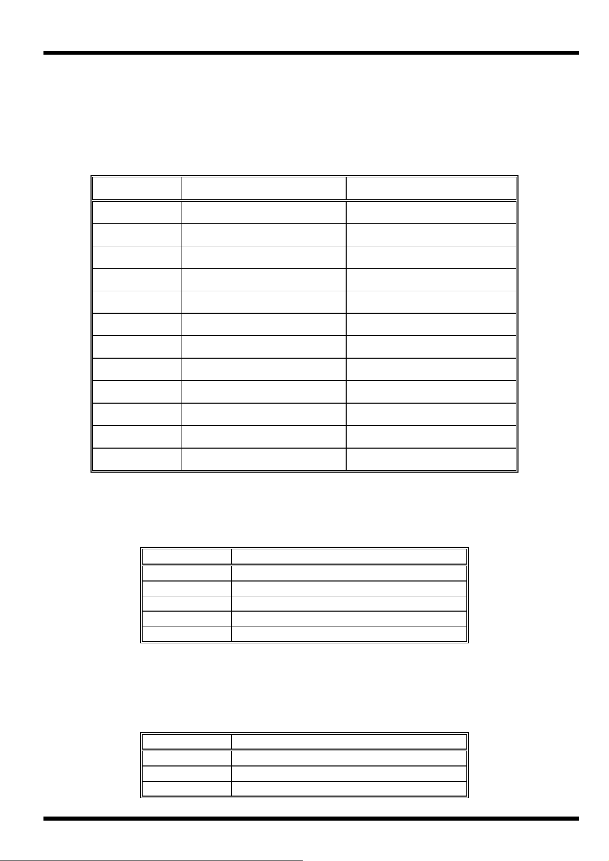
3.15 Coded data fields.
3.15.1 Alarm type codes.
Reading and writing the controller alarm types is possible by use of parameters P (alarm 1)
and S (alarm 2) where the data field of the message is coded as follows.
DATA FIELD S2000 ALARM TYPE P2000 ALARM TYPE
0000 HIGH ALARM HIGH ALARM
0001 LOW ALARM LOW ALARM
0002 INDEXED ALARM INDEXED ALARM
0003 INDEXED HIGH ALARM INDEXED HIGH ALARM
0004 INDEXED LOW ALARM INDEXED LOW ALARM
0005 MANUAL ACK' RELAY MANUAL ACK' RELAY
0006 REMOTE SP ACK' RELAY REMOTE SP ACK' RELAY
0007 INVALID PROGRAM RELAY
0008 INVALID READY RELAY
0009 INVALID UP RAMP RELAY
0010 INVALID DOWN RAMP RELAY
0011 INVALID SOAK RELAY
3.15.2 Setpoint type codes.
The setpoint type (parameter code O) is coded as follows.
DATA FIELD SETPOINT TYPE
0000 HIGH CLAMPED SETPOINT
0001 LOW CLAMPED SETPOINT
0002 INDEXED SETPOINT
0003 REMOTE SETPOINT
0004 INTERNAL SETPOINT
3.15.3 Ratio limit reference type codes.
The ratio limit 1 reference (parameter code I) is coded as follows.
DATA FIELD RATIO REFERENCE TYPE
0000 LIMIT IS OFF
0001 LOAD
0002 SETPOINT
M41 Issue 1.1
Page 16

SERIES 2000 COMMUNICATIONS MANU AL 15
3.15.4 Hold type codes (P2000 Only)
Programmer parameter code I (Hold type) uses coded data of the following form.
DATA FIELD
HOLD TYPE
0000 NO INTERNAL HOLD
0005 HOLD ON RAMPS, ABOVE SETPOINT ONLY
0006 HOLD ON RAMPS, BELOW SETPOINT ONLY
0007 HOLD ON RAMPS, ABOVE AND BELOW SETPOINT
0009 HOLD ON DWELLS, ABOVE SETPOINT ONLY
0010 HOLD ON DWELLS, BELOW SETPOINT ONLY
0011 HOLD ON DWELLS, ABOVE AND BELOW SETPOINT
0013 HOLD ON RAMPS & DWELLS, ABOVE SETPOINT ONLY
0014 HOLD ON RAMPS & DWELLS, BELOW SETPOINT ONLY
0015 HOLD ON RAMPS & DWELLS, ABOVE AND BELOW SETPOINT
M41 Issue 1.1
Page 17

16 SERIES 2000 COMMUNICATIONS MANU AL
APPENDIX A - BASIC COMMUNICATIONS PROGRAM
1000 REM DEMO PROGRAM FOR S2000 COMMUNICATIONS (GW-BASIC V3.23)
1010 ON ERROR GOTO 6000
1020 GOSUB 2000 'INITIALISE
1030 GOSUB 3000 'DRAW SCREEN
1040 WHILE PAUSED=0 'Main loop
1050 KEY (7) STOP:KEY (8) STOP
1060 FOR I=1 TO MAXPRM
1070 KEY (5) STOP:KEY (6) STOP
1080 LOCATE 5+I,1
1090 GOSUB 4000 'Send read question and get answer
1100 GOSUB 5000 'Display answer
1110 KEY (5) ON:KEY (6) ON
1120 NEXT I
1130 KEY (7) ON:KEY (8) ON
1140 WEND
1150 GOTO 1040
2000 REM ***** INITIALISE *************
2010 ON KEY (5) GOSUB 7000 : KEY (5) ON 'Write
2020 ON KEY (6) GOSUB 10000 : KEY (6) ON 'Address
2030 ON KEY (7) GOSUB 11000 : KEY (7) ON 'Pause
2040 ON KEY (8) GOSUB 12000 : KEY (8) ON 'Cont
2050 ON KEY (10) GOSUB 9000 : KEY (10) ON 'Break
2060 WHILE PRAM$(MAXPRM) <>"END"
2070 MAXPRM = MAXPRM+1
2080 READ PRAM$(MAXPRM)
2090 READ PRMCODE$(MAXPRM)
2100 READ PRMMUL(MAXPRM)
2110 READ PRMUNITS$(MAXPRM)
2120 WEND
2130 MAXPRM = MAXPRM-1
2140 OPEN "COM1:1200,O,7,1,DS0,CS0,CD0" AS #1
2150 ADDRESS$= "55" 'Initial controller address
2160 RETURN
2170 REM DATA TABLE. TEXT(18 MAX),PARAMETER LETTER,1/UNIT VALUE,UNITS
2180 DATA "MEASURED VALUE","A",1,"DEG"
2190 DATA "OUTPUT","B",10,"%"
2200 DATA "LOCAL SET POINT","C",1,"DEG"
2210 DATA "PROPBAND","D",10,"%"
2220 DATA "INT ACTION TIME","E",1,"SEC"
2230 DATA "DER ACTION TIME","F",1,"SEC"
2240 DATA "DER APPROACH BAND","G",10,"XP"
2250 DATA "END","",0,""
2260 RETURN
3000 REM ***** DRAW SCREEN ************
3010 SCREEN 0,0:WIDTH 80
3020 CLS
3030 KEY 5,"WRITE"
3040 KEY 6,"ADDR'S"
3050 KEY 7,"PAUSE"
3060 KEY 8,"CONT"
3070 KEY 9,""
3080 KEY 10,"QUIT"
3090 LOCATE 2,24
3100 PRINT "F:G:H S2000 SERIES COMMS DEMO"
3110 LOCATE 4,1
3120 PRINT TAB(4)"Parameter"TAB(23)"Question"TAB(33)"Answer" TAB(52)"Result"
3130 RETURN
4000 REM ***** READ AND GET ANSWER ***
4010 PRINT "->";
4020 TX$="R"+ADDRESS$+PRMCODE$(I)+CHR$(13)
4030 PRINT #1,TX$;
4040 GOSUB 8000 'GET RX$
4050 RETURN
5000 REM ***** DISPLAY QUESTION AND ANSWER
5010 PRINT TAB(4) PRAM$(I); 'Text parameter title
5020 PRINT TAB(23) "R"ADDRESS$+PRMCODE$(I);" = ";RX$ SPACE$(5);
5030 VALUE$=RIGHT$(RX$,5)
M41 Issue 1.1
Page 18

SERIES 2000 COMMUNICATIONS MANU AL 17
5040 IF (LEFT$(VALUE$,1))>"-" THEN VALUE$=RIGHT$(VALUE$,4)
5050 PRINT TAB(48)" = ";
5060 IF (RX$="TIMEOUT") OR (LEFT$(RX$,1)<>"*") THEN GOTO 5090
5070 PRINT VAL(VALUE$)/PRMMUL(I);PRMUNITS$(I);" ";
5080 GOTO 5100
5090 PRINT " ERROR"SPACE$(10);
5100 LOCATE CSRLIN,1:PRINT " ";
5110 RETURN
6000 REM ***** ERROR HANDLER *************
6010 GOSUB 13000 'Position cursor
6020 PRINT " Error Type " ERR "At line "ERL
6030 LOCATE CURY,CURX:RESUME NEXT
7000 REM ***** WRITE TO CONTROLLER ******
7010 GOSUB 13000 'Position cursor
7020 PRINT "Write Parameter ? ";
7030 WPRAM$=INKEY$:IF LEN(WPRAM$)=0 THEN 7030
7040 PRINT WPRAM$;
7050 LINE INPUT;" New Data [-]NNNN ";WDAT$
7060 WTX$="W"+ADDRESS$+WPRAM$+WDAT$
7070 PRINT #1,WTX$+CHR$(13);
7080 GOSUB 8000 'GET RESPONSE RX$
7090 PRINT " "WTX$" = "RX$;
7100 LOCATE CURY,CURX
7110 RETURN
8000 REM ***** GET RESPONSE RX$ *****
8010 RX$="":IN$=""
8020 TIMLIMIT=300 'TIMEOUT LIMIT
8030 TIM=0:TIMOUT=0:RXEND=0
8040 WHILE (RXEND=0) AND (TIMOUT=0)
8050 WHILE NOT EOF(1)
8060 IN$=INPUT$(1,#1)
8070 IF IN$=CHR$(13) THEN RXEND=1 ELSE RX$=RX$+IN$
8080 TIM=0
8090 WEND
8100 TIM=TIM+1
8110 IF TIM>TIMLIMIT THEN TIMOUT=1
8120 WEND
8130 IF TIMOUT <>0 THEN RX$="TIMEOUT"
8140 RETURN
9000 REM *******BREAK - KEY 10 ************
9010 LOCATE 23,1:END
10000 REM ***** CHANGE ADDRESS ***********
10010 GOSUB 13000 'Position cursor
10020 LINE INPUT;" New Address NN ";ADDRESS$
10030 LOCATE CURY,CURX
10040 RETURN
11000 REM ***** PAUSE **********************
11010 GOSUB 13000 'Position cursor
11020 PAUSED=1:PRINT " ** Paused ** "
11030 LOCATE CURY,CURX:RETURN
12000 REM ***** CONT ***********************
12010 GOSUB 13000 'Position cursor
12020 PAUSED=0:PRINT " ** Continue ** "
12030 LOCATE CURY,CURX:RETURN
13000 REM ***** TALK WITH OPERATOR *******
13010 CURX=POS(0):CURY=CSRLIN 'Current curser posn
13020 LOCATE 22,2:PRINT STRING$(77,32):LOCATE 22,2
13030 RETURN
M41 Issue 1.1
 Loading...